
Buckingham 4 CFF40 - Water heaters and boilers Halstead - Free user manual and instructions
Find the device manual for free Buckingham 4 CFF40 Halstead in PDF.


| Product Type | Chimney Fanned Flue Boiler for central heating and indirect domestic hot water |
| Brand | Halstead |
| Model | Buckingham 4 CFF40 |
| GC Number | 41-333-94 |
| Dimensions (H x W x D) | 860–900 mm x 558 mm x 440 mm (adjustable height) |
| Weight | 99 kg (218 lb) |
| Water Content | 5.76 litres (1.27 gallons) |
| Electrical Supply | 230 V ~ 50 Hz, fused 3A, must be earthed |
| Gas Connection | Rc 1/2 (1/2 in BSPT) |
| Water Connections | Rc 1 (1 in BSPT) |
| Gas Rate (CFF40) | 1.7 m³/h (49 ft³/h) at full load |
| Heat Input (Approx.) | 17.9 kW (based on gas rate) |
| Seasonal Efficiency (SEDBUK) | 78.2% (Band D) |
| Burner | Aeromatic, automatic spark ignition |
| Flue Type | Chimney fanned flue, 100 mm (4 in) diameter, with adapter for BS567 |
| Max. Flue Length | 15 m vertical; condensate drain required beyond 6 m |
| Safety Devices | Flame supervision, reset function, air pressure switch, overheat thermostat |
| Control | Single boiler temperature control (max 82°C), remote controls optional |
| Electrical Protection | Fuse type F4A (optional external 3A fuse) |
| Installation Requirement | Open vented system only; not for sealed systems |
| Ventilation | Room: 30 cm²; compartment: high & low vents (see manual) |
| Maintenance | Annual service by competent person recommended |
| Guarantee | Subject to terms; requires completion of Benchmark logbook |
| Spare Parts Availability | Halstead authorised parts only (see section 11 of manual) |
Frequently Asked Questions - Buckingham 4 CFF40 Halstead
User questions about Buckingham 4 CFF40 Halstead
0 question about this device. Answer the ones you know or ask your own.
Ask a new question about this device
Download the instructions for your Water heaters and boilers in PDF format for free! Find your manual Buckingham 4 CFF40 - Halstead and take your electronic device back in hand. On this page are published all the documents necessary for the use of your device. Buckingham 4 CFF40 by Halstead.
USER MANUAL Buckingham 4 CFF40 Halstead
Instructions for Use
Installation and Servicing
To be left with the user
HALSTEAD
Buckingham 4
Chimney Fanned Flue Boiler
Model: CFF40
G.C. No. 41-333-94
Model: CFF50
G.C. No. 41-333-95
Model: CFF60
G.C. No. 41-333-96


The code of practice for the installation, commissioning & servicing of gas central heating
This is a Cat I2H Appliance
Reference in these instructions to British Standards and Statutory Regulations/Requirements apply only to the United Kingdom. For Ireland the rules in force must be used.

The instructions consist of three parts: User, Installation and Servicing Instructions, which includes the Guarantee Registration Card. The instructions are an integral part of the appliance and must, to comply with the current issue of the Gas Safety (Installation and Use) Regulations, be handed to the user on completion of the installation.
Important Information
TESTING AND CERTIFICATION
This boiler is tested and certified for safety and performance. It is therefore important that no alteration is made to the boiler without permission in writing from Halstead Boilers Ltd.
Any alteration not approved by Halstead Boilers Ltd. could invalidate the certification and boiler warranty, and may also infringe the current issue of the Statutory Requirements, see Section 1.3.
CE MARK
This boiler meets the requirements of Statutory Instrument No. 3083 The Boiler (Efficiency) Regulations, and therefore is deemed to meet the requirements of Directive 92/42/EEC on the efficiency requirements for new hot water boilers fired with liquid or gaseous fuels.
Type test for purposes of Regulation 5 certified by: Notified body 0086.
Product/production certified by: Notified body 0086.
The CE mark on this appliance shows compliance with:
- Directive 90/396/EEC on the approximation of the laws of the Member States relating to appliances burning gaseous fuels.
- Directive 73/23/EEC on the harmonization of the laws of the Member States relating to electrical equipment designed for use within certain voltage limits.
- Directive 89/336/EEC on the approximation of the laws of the Member States relating to electromagnetic compatibility.
INFORMATION FOR THE INSTALLER AND SERVICE ENGINEER.
Under Section 6 of The Health and Safety at Work Act 1974, we are required to provide information on substances hazardous to health.
Ceramic Fibre/Insulation Pads, Glass Yarn.
These can cause irritation to skin, eyes and the respiratory tract. If you have a history of skin complaint you may be susceptible to irritation. High dust levels are usual only if the material is broken. Normal handling should not cause discomfort, but follow normal good hygiene and wash your hands before eating, drinking or going to the lavatory. If you do suffer irritation of the eyes or severe irritation to the skin seek medical attention.
SPARE PARTS
REMEMBER, when replacing a part on this appliance, use only spare parts that you can be assured conform to the safety and performance specification that we require. Do not use reconditioned or copy parts that have not been clearly authorised by Halstead Boilers Ltd.
MANUAL HANDLING GUIDANCE
During the appliance installation and the replacement of the heat exchanger it will be necessary to employ caution and assistance whilst lifting as the appliance or component exceeds the recommended weight for a one man lift.
In certain situations it may be required to use a mechanical handling aid.
Take care to avoid trip hazards, slippery or wet surfaces.
| CONTENTS | DESCRIPTION | SECTION | PAGE No. |
| INSTRUCTIONSFOR USE | Introduction 3Lighting the Boiler 4 | ||
| INSTALLATIONINSTRUCTIONS | General Data 1 5Water Systems 2 8Flue & Ventilation 3 9Installation 4 11Electrical Wiring 5 16Commissioning 6 17Instructions to User 7 19 | ||
| SERVICINGINSTRUCTIONS | Servicing 8 19Fault Finding 9 23Replacement Parts 10 26Spare Parts | 11 28 |
Instructions for Use
Introduction
Please read these instructions and follow them carefully for the safe and economical use of your boiler.
The Halstead Buckingham 4 CFF series are fanned flue boilers with a chimney flue adapter. They provide heating and if required, an indirect domestic hot water supply.
The boiler is automatic in operation, having only one user control, the boiler temperature control.
Gas Safety (Installation and Use) Regulations
In your own interests and that of safety, it is the law that ALL gas appliances are installed by a competent person in accordance with the current issue of the above regulations.
WARNINGS
Gas Leak or Fault
If a gas leak fault exists or is suspected, the boiler must be turned off, including the electrical supply, and must not be used until the fault has been put right. Advice/help should be obtained from the local gas undertaking or your installation/servicing company.
Clearances
Make sure that nothing obstructs the ventilation grills or clearances.
Minimum clearances must be left around the boiler as shown in diagrams 1.6, 1.7 & 1.8.
Sheet Metal Parts
This boiler contains metal parts (components) and care should be taken when handling and cleaning, with particular regard to edges.
Cleaning
Keep the casing clean by wiping it occasionally with a damp soapy cloth and dry with a polishing cloth.
Do not use abrasive cleaners.
Boilers Installed in a Compartment
If the boiler is fitted in a compartment, cupboard, etc., do not obstruct the purpose-built compartment vents or the grill on the boiler.
Do not use the compartment for storage purposes.
Protection Against Freezing
If the boiler is to be out of use for any period of time during severe weather conditions we recommend the whole system including the boiler, be drained off to avoid the risk of freezing up. If an immersion heater is fitted to the hot water cylinder make sure it is switched off.
Maintenance
To ensure the continued efficient and safe operation of the boiler it is recommended that it is checked and serviced as necessary at regular intervals. The frequency of servicing will depend upon the particular installation conditions and usage, but in general once a year should be enough.
It is the law that servicing must be carried out by a competent person.
If this appliance is installed in a rented property there is a duty of care imposed on the owner of the property by the current issue of the Gas Safety (Installation and Use) Regulations, Section 35.
To obtain service please call your installer or Halstead Boilers using the telephone number given on the inside of the front panel.
Please be advised that the 'Benchmark' logbook should be completed by the installation engineer on completion of commissioning and servicing.
All CORGI Registered Installers carry a CORGI ID card, and have a registration number. Both should be recorded in your boiler Logbook. You can check your installer is CORGI registered by calling CORGI direct on :- 01256 372300.
Boiler Electrical Supply
THIS BOILER MUST BE EARTHED.
The boiler must only be connected to a 230V~50Hz supply protected by a 3A fuse, maximum.
All wiring must be in accordance with the current issue of BS7671.
Heat resistant flexible cable having a conductor size of 0.75mm², to the current issue of BS6500 Table 16 must be used.
To Connect an Electrical Plug
The standard colours of three core flexible cable are,
Brown - live, Blue - neutral, Green and Yellow - earth.
As the markings on your plug may not correspond with these colours, continue as follows:
The Blue cable must be connected to the terminal marked "N" or "Black".
The Brown cable must be connected to the terminal marked "L" or "Red".
The Green and yellow cable must be connected to the terminal marked "E" or "Green" or the earth symbol ⏻.
Instructions for Use
To Turn the Appliance On
Turn the electrical supply on to the boiler and check that all remote controls are calling for heat.
Turn the boiler temperature control clockwise to any position between "0" and MAX, see diagram 1.
"Max" is approximately 82°C (180°F).
The boiler lighting operation is now automatic as follows:
The fan operates and after a short period of time, the spark ignition operates, the solenoid opens, then the burner will light shown by the burner ON neon (green) on the control panel lighting up.
The burner will remain alight until switched off by the control thermostat or any remote control.
Note: If the boiler is turned OFF at the boiler temperature control, wait at least 30 seconds before switching on again.
When the boiler switches off, the burner will go out.
The automatic lighting sequence will operate again when heat is required.
It should be noted that this is a fanned flue appliance and fan operation may be heard.
If the reset neon lights, turn the boiler temperature control to "0" (off), wait 30 seconds, then repeat the lighting instructions.
To Turn the Appliance Off
For short periods, turn the boiler temperature control fully anticlockwise to "0" (off).
To relight, turn the boiler temperature control to any position between "0" and "MAX".
For longer periods, turn the boiler temperature control fully anticlockwise to "0" (off) and switch off the electrical supply to the boiler.
To relight follow the lighting sequence given above.

1 General Data

NOTE: The boiler casing can be set at two heights, MAX.or MIN.
© WATER CONNECTIONS Rc1 reduced with DISTRIBUTOR TUBE to Rc 3/4 (3/4 in. B.S.P.T.) (pumped return)
WATER CONNECTIONS Rc1 (1in. B.S.P.T.)
GAS CONNECTION Rc 1/2 (1/2 in. B.S.P.T.)
*INSIDE DIAMETER OF ADAPTER FOR 100mm (4in.) NOMINAL DIAMETER FLUE TO BS567
Diagram 1.1
| A | B | C | D | E | F | G | H | J | K | L | ||
| 300 | 115 | 558 | 294 | 384 | 555 | 440 | 3 | Max 900/Min 860 | 300 | 80 | 32 |
Important Notice
This boiler is for use only on G20 gas.
Wherever possible, all materials, appliances and components to be used shall comply with the requirements of applicable British Standards.
Where no British Standard exists, materials and equipment should be fit for their purpose and of suitable quality and workmanship.
Refer to Manual Handling Operations, 1992 Regulations.
Sheet Metal Parts
WARNING. When installing or servicing this boiler, care should be taken to avoid any possibility of personal injury when handling the edges of sheet metal parts.
1.1 Technical Data
Refer to diagrams 1.1, 1.2, 1.3 and 1.4.
All dimensions are given in millimetres (except as noted).
Approximate weight of complete boiler : 99kg (218lb)
Water content : 5.76 litre (1.27gallons)
Gas connection : Rc 1/2 (1/2 in BSPT)
Water connection : Rc1 (1in BSPT)
Electrical supply: 230V~50Hz, fused 3A
Burner: Aeromatic
The Seasonal Efficiency of Domestic Boilers in the UK (SEDBUK) is "D" CFF40 - 78.2% CFF50 - 78.4% CFF60 - 78.4%.
The value is used in the UK Government's Standard Assessment Procedure (SAP) for energy rating of dwellings. The test data from which it has been calculated have been certified by B.S.I.
1.2 Range Rating
See diagrams 1.2, 1.3 & 1.4 for boiler ratings.

1 General Data
1.3 Statutory Requirements
The installation of this appliance must be carried out by a competent person and must be in accordance with the relevant requirements of the current issue of:
Manufacturer's instructions supplied.
The Gas Safety (Installation and Use) Regulations, Building Regulations, Local Water Company Bye-laws, The Building Standards (Scotland) Regulations, (applicable in Scotland), Health and Safety at Work Act, Control of Substances Hazardous to Health, Electricity at Work Regulations and any applicable local regulations.
Detailed recommendations are contained in the current issue of the following British Standards and Codes of Practice,
BS6891, BS5440 Part 1 and 2, BS6798, BS5449, BS5546, BS6700, BS7478, BS7593, BS7671.
Manufacturer's instructions must not be taken as overriding statutory requirements.
1.4 B.S.I Certification
This boiler is certified by B.S.I. for safety and performance. It is, therefore, important that no alteration is made to the boiler unless agreed, in writing, by Halstead Boilers Ltd.
Any alteration not approved by Halstead Boilers Ltd. could invalidate the B.S.I. certification, boiler warranty, and could infringe the current issue of the Statutory Requirements.
1.5 Gas Supply
The gas installation should be fitted in accordance with the current issue of BS6891.
The supply from the governed meter must be of adequate size to provide a steady inlet working pressure of 20mbar (8in wg) at the boiler.
On completion, test the gas installation using the pressure drop method and suitable leak detection fluid, and purge in accordance with the current issue of BS6891.
1.6 Electrical
WARNING. This boiler must be earthed.
The electrical installation must be carried out by a competent person. All external components shall be of the approved type and shall be connected in accordance with the current issue of BS7671 and any local regulations which apply.
Connection of the boiler and any system controls to the mains supply through an unswitched shuttered socket outlet and 3A fused 3-pin plug, both to the current issue of BS1363. Alternatively, a 3A fused double pole isolating switch may be used, having a minimum double pole contact separation of 3mm, serving only the boiler and system controls.
Heat resistant cable of at least 0.75mm² (24/0.20mm), to the current issue of BS6500 Table 16, must be used for all connections within the boiler casing, to the control box, pump, etc.
1.7 Condensate Drain
A plastic drain pipe may need to be fitted to allow discharge of condensate to a drain.
Condensate should, if possible, be discharged into the internal household draining system. If this is not practical, discharge can be made externally into the household drainage system or a purpose designed soak away; see section 4.10 for more details.
HALSTEAD
Buckingham 4 CFF50
Halstead Boilers Ltd. 20/22 First Avenue, Bluebridge Industrial Est. Halstead, Essex, CO9 2EX. Service - 01926 834834, Sales - 01787 475557 2000462677
| Electrical Supply 230V ~ 50Hz37W Fused at 3AFor use on I2H G20- 20mbar.This boiler is intended exclusivelyto be installed on a gas supplywith a governed meter. | GC No.41-333-95 |
| TYPE : B22 | |
| NOx Class 1 | |
| CE 0086 | |
| GB IE | |
| HEATING CIRCUIT PMS = 2.5 bar | 0086/AS/031 |
| INJECTOR: 3.6mm PART No. 205729 | |
| HOT BURNER PR - mbar (in.w.g) | 11.7 (4.7) |
| HEAT INPUT NETT Q- kW (Btu/h) | 16.16(55,138) |
| HEAT OUTPUT P- kW (Btu/h) | 14.65(50,000) |
| SERIAL No. | |
2000462677
10186
Diagram 1.3
HALSTEAD
Buckingham 4 CFF60
Halstead Boilers Ltd. 20/22 First Avenue, Bluebridge Industrial Est. Halstead, Essex, CO9 2EX. Service - 01926 834834, Sales - 01787 475557 2000462727
10187
| Electrical Supply 230V ~ 50Hz37W Fused at 3AFor use on I2H G20- 20mbar.This boiler is intended exclusivelyto be installed on a gas supplywith a governed meter. | GC No.41-333-96 |
| TYPE : B22 | |
| NOx Class 1 | |
| CE 0086 | |
| GB IE | |
| HEATING CIRCUIT PMS = 2.5 bar | 0086/AS/031 |
| INJECTOR: 3.5mm PART No. 2000461837 | |
| HOT BURNER PR - mbar (in.w.g) | 14.6 (5.87) |
| HEAT INPUT NETT Q- kW (Btu/h) | 18.77(64,043) |
| HEAT OUTPUT P- kW (Btu/h) | 17.00(58,000) |
| SERIAL No. | |
Diagram 1.4

1 General Data
1.8 Boiler Location
This boiler is not suitable for outside installation.
The boiler casing can be fitted at two heights. Refer to diagram 1.5.
The boiler is assembled at the factory with the control box and heat shield fitted in the lower position.
The boiler must stand on a level floor, conforming with local authority requirements and building regulations.
The base temperature is within the requirements of the current issue of BS5258. The boiler may stand on a wooden floor but a metal base plate is required to protect plastic tiles and similar floor coverings.
Suitable installation clearance needs to be available at the sides of the boiler to facilitate direct connection of pipework and making good around the flue assembly. The actual clearance required will vary with site conditions.
When the boiler is to be installed level with work surfaces, minimum clearances should be provided as shown in diagram 1.6. Work tops which overhang the cupboard sides, almost in contact with the casing top, require a larger minimum air gap. Flush sided fixtures require the same overall minimum space but can have a reduced air gap on one side.
Boilers to be installed under work tops or fixtures, should be positioned to provide minimum clearances as shown in diagram 1.7. To facilitate minimum clearances it may be necessary to modify kitchen units and fixtures.
Combustible material must be 25mm (1in) away from flue components see diagram 1.7.
A front access clearance for servicing of 700mm, should be provided from a permanent wall or fixture.
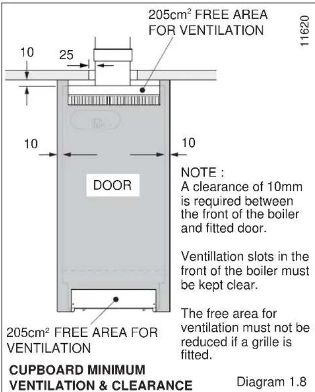
The boiler can be installed within a cupboard, refer to minimum ventilation and clearances as shown in diagram 1.8.
If the boiler is to be installed in a cupboard or compartment, make sure that nothing will obstruct the openings/vents in the compartment.
A compartment used to enclose the boiler must be designed and constructed specifically for this purpose. An existing cupboard or compartment modified for the purpose may be used. Details of essential features of cupboard or compartment design are given in the current issue of BS6798.
The boiler must not be installed in a room used or intended to be used as sleeping accommodation or a room containing a bath or shower.
Where the installation of the boiler will be in an unusual location, special procedures are necessary the current issue of BS6798 gives detailed guidance on this aspect.
1.9 Heating System Controls
The heating system should have installed: a programmer and room thermostat controlling the boiler.
Thermostatic radiator valves may be installed, however they must not be fitted in a room where the room thermostat is located.
Note: For further information, see the current issue of the Building Regulations, approved document L1, and the references:
1) GIL 59, 2000: Central heating system specification (CheSS) and
2) GPG 302, 2001: Controls for domestic central heating system and hot water. BRECSU.


2 Water Systems
2.1 Water Pressure Head
The boiler shall only be connected to a cistern water supply with a minimum head of 1 metre (3ft 3in) and a maximum head of 27 metres (90ft) which has an open vent in the system.
The working pressure must be within the range 0.1bar to 2.7bar (1.3 to 39lbftin4).
The boiler MUST NOT be connected to a sealed water system.
2.2 Inhibitor
Attention is drawn to the current issue of BS5449 and BS7593 on the use of inhibitors in central heating systems.
If an inhibitor is to be used in the system, contact should be made with the inhibitor manufacturers so that they can recommend their most suitable product.
When using in an existing system take special care to drain the entire system, including the radiators, then thoroughly clean out before fitting the boiler whether or not adding an inhibitor.
2.3 Gravity Domestic and Pumped Heating
It is recommended that a cylinder thermostat is used to prevent the stored water temperature becoming unnecessarily high when the central heating pump is off.
The domestic primary flow and return must be 28mm o.d. The installation must comply with the current issue of BS5546 and BS6700, see diagram 2.1.
If the above conditions cannot be met, it is suggested that a fully pumped system be used.
2.4 Pumped Heating and Hot Water
Where a single flow and return is taken from the boiler, a minimum static head of 1 metre (3ft 3in) must be provided between the water line of the feed tank and the centre of the waterway, see diagram 2.2.
2.5 Circulation Pump
Normally the pump should be set to give a temperature difference of 11°C (20°F) across the boiler. At the appropriate pumped flow rate the pressure loss through the boiler can be found from the graph, diagram 2.3.
Use a pump with integral valves or fit isolating valves as close to the pump as possible.
2.6. Cylinder
For all systems supplying domestic hot water the cylinder must be indirect.
2.7 Safety Valve
A safety valve need not be fitted to an open vented system.
2.8 Draining Tap
A draining tap must be provided at the lowest points of the system which will allow the draining of the entire system, including the boiler and hot water cylinder.
Draining taps should be to the current issue of BS2879.
2.9 Thermostatic Radiator Valves
If thermostatic radiator valves are fitted care must be taken to ensure that there is an adequate flow rate through the boiler when they close, refer to the current issue of BS7478 for guidance. If fitted to all radiators ensure a bypass is fitted and adjust to achieve a temperature difference no greater than 20°C between flow and return with the thermostatic valves closed.


3 Flue and Ventilation
Important Notes
The flue must be installed in accordance with the rules in force in the countries of destination.
The flue must be in accordance with the current issue of BS5440 Part 1.
The Chimney Flue Adapter Kit (Pt. No. 2000461993) socket is designed to take flue pipes to the current issue of BS567. If a flue pipe to BS715 is to be used, an adapter must be fitted to the boiler flue socket.
The flue must be at least equivalent to 1m vertical.
The maximum flue length must not exceed 15m vertical.
If the flue length exceeds the following:
CFF40 - 6m, CFF50 - 9m, CFF60 - 9m
the condensate drain on the chimney flue adapter must be connected and we would recommend that one of the following flue liners should be used or an equivalent specification:
Ritevent - Chimflex LW or SB
Selkirk - Selflex TS or TSE
An existing liner must be changed if there is any doubt that it will not operate safely throughout the life of any new appliance.
A drain point is incorporated on the chimney flue adapter to which a drain pipe can be connected, refer to section 4.10.
3.1 Flue Guidelines
The flue should be kept as short as possible. Horizontal or very shallow runs of the flue should be avoided as they encourage local cooling.
Always choose a flue route which will cause the least cooling of the flue.
90° elbows should not be used.
The existing flue may not be completely sound. Therefore, to prevent the possibility of leakage, additional sealing MUST be carried out between the base of the chimney and the flue liner.
The end of the flue liner at the chimney top must be adequately sealed and clamped, using proprietary fittings suitable for the flue liner used, see diagram 3.1.
The flue should, preferably, end above ridge height but at the least above the eaves of a pitched roof. Use a certificated terminal.
If the flue is passed through or near any combustible material it should be installed in accordance with the current issue of BS5440 Part 1.3. If in doubt seek advice from the local gas undertaking or Halstead Boilers Ltd.
3.2 Existing Chimney
An existing brick chimney must be thoroughly swept and all debris cleared away before lining.
Remove any damper or register plate. Alternatively it may be locked in the fully open position.
A flexible flue liner is preferred but a rigid liner may be used, with connection to the boiler flue socket made with a short vertical piece of flexible liner, see diagram 3.2.
The sealing plate also prevents debris falling and gives the flue better insulation, reducing the possibility of condensation, see diagram 3.1.
Check the system efficiency before installing the boiler.


3.3 New Chimney
A newly built chimney can be lined with a moisture resistant lining, such as salt glazed pipe, of an appropriate diameter as specified in the Building Regulations.
In the case of a salt-glazed lined flue, it is recommended that a short vertical length of flue pipe, preferably flexible metallic, be used. Fix and seal it to the boiler flue socket and make good with an approved seal.
If a flue and false chimney breast are to be constructed, all openings for pipework to upper floors, etc., must be sealed.
If a specially built compartment is constructed for the boiler, it must conform to the requirements of the current issue of BS5440 Part 1 and BS5871.
3 Flue and Ventilation
3.4 Timber Frame Buildings
If the boiler is to be installed in a timber frame building, it should be fitted in accordance with the Institute of Gas Engineers document IGE/UP/7/1998. If in doubt, seek advice from the local gas undertaking or Halstead Boilers Ltd.
3.5 Ventilation for Boiler Installed in a Room or Space
If the boiler is to be installed in a room or space, a purpose-designed permanent ventilation opening, to supply air for combustion, must be provided on an outside wall to external air. Refer to the current issue of BS5440 Part 2 for details.
The opening may be directly into the room or the space containing the boiler, or an outside wall of an adjacent room or space which has an internal permanent air vent, of the same size, into the room or space containing the boiler.
Do not ventilate through a bedroom, bedsitting room, private garage, or a room containing a bath or shower.
When the boiler is installed in a room or internal space already containing other fuel-burning appliances, then the air supply of such appliances must be taken into account.
The ventilation opening areas are given in "Air Vent Table". The figures quoted refer to the minimum acceptable effective area.
3.6 Ventilation for Boilers Installed in a Compartment
When the boiler is fitted in a compartment, high and low level purpose-designed, permanent openings must be provided to supply air for combustion and compartment ventilation.
The cupboard containing the boiler must have the door removed for ventilation reasons.
The air vents must have minimum areas, see "Compartment Air Vent table". The figures quoted refer to the minimum acceptable effective area.
Both the high and low level openings must communicate with the same room, or must both be on the same wall to outside air.
If air vent grilles are fitted to a cavity wall, the opening through the wall must be ducted.
Where ventilation air to a compartment is taken from a room or space, then the room or space must be fitted with a ventilation opening as specified in "Air Vent Table".
For information regarding compartment requirements refer to the appropriate section of the current issue of BS6798.
3.7 Ventilation for Boilers installed in a Cupboard
For minimum ventilation and clearances for cupboard installation refer to section 1.8 and diagram 1.8.
3.8 Extract Fans
If an extract fan is fitted in the premises, there is a possibility that if adequate inlet openings are not provided, spillage of the products from the boiler could occur.
When openings are fitted in accordance with the current issue of BS5440 Part 2 and this section, extract fans should not cause down draught, but where such fan installations are found, a spillage test must be carried out in accordance with the current issue of BS5440 Part 1 and any corrective work done.
| AIR VENT TABLE- FOR ROOM/ SPACE INSTALLATIONS | ||
| EFFECTIVE AREA OF VENT | ||
| CFF40 30cm2 | 2 | 4.7 in2 |
| CFF50 46cm2 | 2 | 7.1 in2 |
| CFF60 59cm2 | 2 | 9.2 in2 |
| COMPARTMENT AIR VENT TABLE | |||||
| COMPARTMENT VENTILATION REQUIREMENTS | HIGH LEVEL LOW LEVEL VENT AREA VENT AREA | ||||
| VENTILATION FROM ROOM OR SPACE | CFF40 | 130cm2 | 21in2 | 259cm2 | 41in2 |
| CFF50 | 162cm2 | 25in2 | 323cm2 | 51in2 | |
| CFF60 | 188cm2 | 30in2 | 376cm2 | 59in2 | |
| FROM OUTSIDE | CFF40 | 65cm2 | 10in2 | 130cm2 | 21in2 |
| CFF50 | 81cm2 | 13in2 | 162cm2 | 25in2 | |
| CFF60 | 94cm2 | 15in2 | 188cm2 | 30in2 | |
4 Installation
General Installation Notes
The appliance pack contains :-
Boiler.
Casing panels, packed separately.
Loose items fittings pack, see list in pack.
The chimney flue adapter with flue extension is supplied separately.
Before installation of the boiler make sure that the location selected is in accordance with the requirements of Section 1.8.
4.1 Unpacking
The boiler casing panels are packed separately within the main carton and are designed to enable gas and water connections to be made before fitting the casing panels.
The casing brackets, flue restrictor, distributor tube and other loose items, are in the fittings pack.
IMPORTANT. With regards to the Manual Handling Operations, 1992 Regulations, the following operation exceeds the recommended weight for one man lift.
4.2 Water Connections - Gravity Domestic and Pumped Heating
Fit suitable fittings into the boiler tappings, see diagram 4.1.
Make sure that all pipes are taken backwards and will clear the casings.
Heating flow: Any one of the four upper connections may be used.
Domestic flow: Any one of the three remaining upper connections may be used.
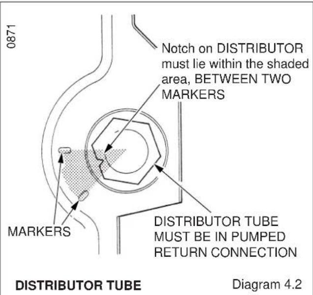
Heating return: The water distributor tube must be fitted into either of the front lower connections on all installations, see diagram 4.2. This tube is in the fittings pack.
Domestic return: Any one of the three remaining lower connections may be used for the gravity domestic hot water return.
Fit plugs into any unused boiler tappings.
4.3 Water Connections - Fully Pumped Systems
Fit suitable fittings into the boiler tappings as required, see diagram 4.3. Make sure that all pipes are taken backwards and will clear the casings.
It is important that all connections are made as shown in diagram 4.3.
Fit the water distributor tube into the return connection, see diagram 4.2. This tube is packed in the fittings pack.
Fit plugs into any unused boiler tappings.

WATER CONNECTIONS - GRAVITY DOMESTIC, PUMPED HEATING Diagram 4.1

4 Installation
4.4 Pipework
When the front tappings are used, it is essential that any pipework or fittings do not project more than shown in diagram 4.4.
When using a rear tapping with Rc (1 in BSP) fitting for 28mm od pipework, it is recommended that a short nipple and an Rc thread (BSP) to copper elbow is used. If the pipework is required to run back to the wall, make sure that it will clear the boiler air duct and, if working to minimum clearance, does not project too far from the boiler, see diagram 4.5.
Do not route any pipework, water or gas, across the front of the combustion chamber cover.
The gas pipework must be along the left hand side of the boiler.


4.5 Casing Brackets
Loosen the side insulation blankets by removing the securing bracket, see diagram 4.6 and fit the two upper and two front casing brackets shown in diagram 4.7, using the No.8 screws provided.
Ensure insulation blankets are replaced as before and secure as diagram 4.6.
NOTE: The screws will already be fitted.
Push the captive nuts, supplied loose, on to the casing brackets as shown in diagram 4.7.


4 Installation
4.6 Side Casings
Fit the side casings by locating their lugs into the appropriate slot in the boiler plinth, see diagram 4.8, depending on the required height, there are two options, see section 1.7.
Secure the casing sides to the front and rear upper casing brackets with self-tapping screws supplied, see diagrams 4.8 and 4.9.
Note: If the side in-fill panel is being fitted it should be fitted at the same time as the side casing, see next section.
4.7 Side In-fill Panel (If required)
A side in-fill panel is supplied with the boiler, which can be fitted at the rear of the left or right hand side casing but can be discarded if the water connections are made on both sides of the boiler or if the boiler is screened by fixtures. The in-fill panel will usually be fitted on the side where there are no pipework connections.
Insert the push fit plastic location peg, supplied, through the in-fill panel and side casing holes and secure with the spring clips, see diagram 4.10.
NOTE
The boiler is assembled at the factory with the control box and heat shield fitted in the lower casing height position.


4 Installation
4.8 Flue / Boiler Connection
Remove the three self-tapping screws from the lower part of the control box support bracket, see diagram 4.11.
Undo the wing nut that secures the top of the heat shield and carefully hinge down the control box and heat shield, see diagram 4.11.
Release the two toggle latches that secure the fan access door and remove it, see diagram 4.12.
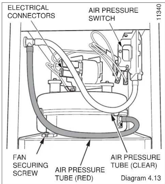
Remove the electrical connections from the fan by pulling the insulation boots only, and disconnect the two air pressure tubes, noting their positions, see diagram 4.13.
Remove the fan assembly from the flue hood by removing the securing screw, pull forward and lift up to release the 3 hooked securing lugs underneath the fan, see diagrams 4.13 & 4.14.
From the Chimney Flue Adapter Kit, take the flue spigot; the gasket is supplied in the loose items fittings kit.
Connect the flue spigot and gasket to the top flue outlet of the boiler using the self-tapping screws provided, see diagram 4.15.
From the Chimney Flue Adapter Kit, take the chimney flue adapter and remove the restrictor securing screw.
Fit the restrictor supplied in the loose items fittings kit and secure it in place with the previously removed screw. To connect a condensate drain, remove the plastic end stop by depressing the collet.
NOTE: No restrictor is required for the CFF 40.
Slide the Chimney Flue Adapter into the flue spigot until it engages in the bayonet connection, then twist clockwise to lock, see diagram 4.15.
Rest the flue duct extension on the support bracket and engage it into the chimney flue adapter, see diagram 4.16. Refit the fan, ensuring it is engaged into the flue duct extension and the securing lugs are located correctly into the flue hood, secure with the fan securing screw. Replace the electrical connections and air pressure tubes.
The polarity of the electrical connections is not important.
Make sure that the air pressure tubes are fitted as before, see diagram 4.13, and that the fan duct engages fully into the flue duct extension piece.

IMPORTANT. With regards to the Manual Handling Operations, 1992 Regulations, the following operation exceeds the recommended weight for one man lift.
Place the boiler in position, taking care not to damage the casing panels.
Flue Connection
NOTE: Fix and seal the flue to the hood of the chimney flue adapter in accordance with normal practice.
The flue should be 100mm (4in) nominal diameter, refer to section 3.

4 Installation
4.9 Water & Gas connections
Replace fan access door, heat shield and control box.
Note: When replacing the fan access door make sure the lip at the top of door fits into and behind the slotted bracket located at the top of the boiler.
As there are two casing height options, the control box height and the heat shield may have to be adjusted to suit your requirements.
Complete the water connections to the boiler.
Fill, vent and flush the system.
Check for any water leaks and put right.
Make the gas connection to the service cock, at the lower left hand side of the boiler, see diagram 1.1.
The whole of the gas installation, including the meter, should be inspected, tested for soundness and purged in accordance with the current issue of BS6891.


4.10 Condensate Drain Connection (If Applicable)
With reference to Section 3, should your flue be greater than the "Dry" flue length stated, then a condensation drain should be fitted.
To use the condensate drain connection on the chimney flue adapter, remove end stop, see diagram 4.15. A 22mm plastic overflow pipe should be used to fit on to the drain connection and discharge to a drain. The drain pipe should have a fall of at least 2.5° away from the boiler and should incorporate a 'U' trap.
Condensate should, if possible, be discharged into the household internal drainage system. If this is not practicable, discharge can be allowed into the external household drains or by a purpose designed soak away.
It is recommended that any external condensate drain is insulated and also preferably of 32mm diameter, to prevent freezing in adverse weather conditions.
4.11 Top Casing
Refer to diagram 4.17.
Fit two plastic pegs, one on each side, in the holes on the top casing. The plastic pegs are a tight fit and are best pushed home with a flat faced tool.
Secure front of top casing with the two screws provided.


5 Electrical Wiring


TERMINAL BLOCK CONNECTIONS Diagram 5.1
5.1 Control Box Access
Remove control box cover by undoing the four securing screws (two on control box, two on the heat shield) and lift off, see diagram 5.1.
5.2 Electrical Connections
WARNING. This boiler must be earthed.
Take care not to damage any internal wiring.
Using heat resistant (85°C) cable of at least 0.75mm² (24/0.2mm) and of a suitable length, route as shown in diagram 5.2. Thread through the grommet at the bottom rear of the control box, through the cable clamp and connect to appropriate terminals. Tighten cable clamp screws, see diagram 5.3.
Standard colours are, brown - live (L), blue - neutral (N) and green/yellow - earth ⊕.
The mains cable outer insulation must not be cut back external to the cable clamp.
Make sure the cable is suitably secured.
When making connections make sure that the earth conductor is made of a greater length than the current carrying conductors, so that if the cable is strained the earth conductor would be the last to become disconnected.
5.3 Pump Connection
The pump must be connected to the external controls.
5.4 Testing - Electrical
Checks to ensure electrical safety must be carried out by a competent person.
After installation of the system, preliminary electrical system checks as below should be carried out.
- Test insulation resistance to earth.
- Test earth continuity and short circuit of all cables.
- Test the polarity of the mains.
The installer is requested to advise and give guidance to the user of the controls scheme used with the boiler.
Replace the control box cover.
HEAT RESISTANT CABLE
Diagram 5.2

MAINS INLET CONNECTOR Diagram 5.3
6 Commissioning
IMPORTANT NOTE
The WARNING NOTICE attached to the front casing must only be removed by the user.
Please ensure the "Benchmark" logbook is completed and left with the user, and the magnetic lighting instruction label is placed on the surface of the boiler casing.
6.1 All Systems
Commissioning should be carried out by a competent person in accordance with the current issue of BS6798.
UNDER ALL CIRCUMSTANCES the case must be correctly fitted and sealed, unless fault finding.
Make sure that the system has been thoroughly flushed out with cold water without the pump in place.
Refit the pump, fill the system with water, ensuring that all the air is properly vented from the system and pump.
6.2 Initial Lighting and Testing
CAUTION. This work must be carried out by a competent person, in accordance with the current issue of BS6798.
Make sure that all naked lights and cigarettes are extinguished.
Refer to 'Instructions for Use' and identify the controls.
Check that the boiler is isolated from the electrical supply.
Turn the gas service cock "On", see diagram 6.1.
Purge in accordance with the current issue of BS6891.
WARNING. The multifunctional control and fan operate on mains voltage, terminals will become live.
If programmer control is fitted, make sure it is in the ON mode.
Make sure that any remote controls are calling for heat.
Turn the boiler temperature control clockwise to "Max".
The ignition system will operate to light the boiler. After a pre-set time if ignition has not taken place the boiler will shutdown.
To re-start the lighting sequence, turn the boiler temperature control to "O", then fully clockwise to "Max".
"Max" is approximately 82°C (180°F).
After the burner has lit, the "Burner on" neon on the control panel will come on.
Isolate the boiler from the electrical supply.
Loosen the burner pressure test point screw and connect a suitable pressure gauge, see diagram 6.1.
Switch on the electrical supply to the boiler.
WARNING. The multifunctional control and fan operate on mains voltage, terminals will become live.
6.3 Testing - Electrical
Turn the boiler temperature control fully clockwise to the maximum setting.
The lighting sequence is automatic as follows:
The fan operates and after a short period of time, the spark ignition operates, the solenoid opens, then the burner will light shown by the "Burner On" neon on the control panel lighting up.
The burner will remain alight until switched off, either by the boiler temperature control, programmer (if fitted) or any remote system control.
To make sure that the flame supervision device is working correctly the following should be done.
With the burner alight, turn the gas service cock "Off", see diagram 6.1.
After a short period the burner will go out.

BOILER COMPONENTS H
10052
A CONTROL BOX B PHIAL POCKET C GAS SERVICE COCK D "BURNER ON" NEON E RESET NEON F TEMPERATURE CONTROL G BURNER PRESSURE TEST POINT H GAS PRESSURE ADJUSTMENT SCREW J DATA LABEL
Diagram 6.1
6 Commissioning
The correct working of the flame supervision is shown by the "Burner On" neon going out and the ignition sequence starting up.
After a short period the boiler will shut down.
If the lighting sequence described fails, refer to fault finding section 9.
To carry on, turn the gas service cock "On", see diagram 6.1.
To re-start the lighting sequence, turn the burner temperature control to "0" then fully clockwise to "Max.".
During normal operation when the boiler switches "Off", the burner will go out. The automatic lighting sequence will work again when heat is required.
If the reset neon lights, turn the boiler temperature control to "0" (off), wait 30 seconds, then repeat the lighting instructions.
6.4 Testing - Gas
With the boiler on, proceed as follows:
Test for gas soundness around the boiler gas components using a suitable leak detection fluid, in accordance with the current issue of BS6891.
Check the burner gas pressure at least 10 minutes after boiler has lit, refer to Data Label, see diagrams 1.2, 1.3 & 1.4.
If necessary, adjust the gas pressure to obtain the required setting by turning the screw clockwise to decrease pressure, see diagram 6.1.
Should any doubt exist about the gas rate, check it using the gas meter test dial and stop watch at least 10 minutes after the burner has lit, making sure that all other gas burning appliances and pilot lights are off.
The gas rates: Buckingham 4 CFF40 : 1.7m³/h (49ft³/h)
Buckingham 4 CFF50 : 2.1m³/h (60ft³/h)
Buckingham 4 CFF60 : 2.5m³/h (70ft³/h)
are for guidance only, dependent on the heat setting.
Turn the boiler temperature control fully anti-clockwise to "0".
Isolate from the electrical supply.
Remove the pressure gauge from the test point and refit screw, making sure a gas tight seal is made.
When the boiler temperature control is turned to the "0" position, by hand, wait at least 30 seconds before turning On again.
There may be an initial smell given off from the boiler when new, this is quite normal and it will disappear after a short period of time.
6.5 Testing - All Water Systems
Allow the system to reach maximum working temperature and examine for water leaks.
There should be no undue noise in the system.
The boiler should then be turned off and the system drained off as rapidly as possible, whilst still hot.
Refill system.
6.6 Open Vented System
Ensure there is no pumping over of water or entry of air at the open vent above the feed and expansion cistern.
6.7 Adjustment - Fully Pumped Open Vented System
When commissioning the system the boiler should first be fired on full service, that is, central heating and domestic hot water. Adjust the pump to the system design setting, then balance the system, making adjustments as necessary.
6.8 Completion
Adjust the boiler temperature control and any system controls to their required settings.
Fit the bottom plinth panel and secure with two dog point screws, see diagram 6.2.
Finally fit the front panel by hooking under front of top panel locating on the two studs and securing at the bottom on to the bottom plinth panel with two screws, see diagram 6.3.


7 Instructions to the User
Instruct and demonstrate the safe and efficient operation of the boiler, heating system and domestic hot water system.
Advise the user, that to ensure the continued efficient and safe operation of the boiler, it is recommended that it is checked and serviced at regular intervals. The frequency of servicing will depend upon the particular installation and usage, but in general once a year should be enough.
Draw attention, if applicable to the current issue of the Gas Safety (Installation and Use) Regulations, Section 35, which imposes a duty of care on all persons who let out any property containing a gas appliance.
It is the Law that servicing is carried out by a competent person.
Advise the user of the precautions necessary to prevent damage to the system and building in the event of the heating system being out of use during frost and freezing conditions.
Reminder - Leave these instructions and the "Benchmark" logbook with the user.
8 Servicing
REMEMBER, When replacing a part on this appliance, use only spare parts that you can be assured conform to the safety and performance specification that we require. Do not use reconditioned or copy parts that have not been clearly authorised by Halstead Boilers Ltd.
Products of Combustion Check
Note: To obtain a products of combustion reading, remove the front panel and remove the control box as described in the relevant paragraphs of section 4.8. Next, remove the cap from the sampling point, located on the top of the left hand side of the inner casing, see diagram 8.1.
Connect the analyser tube on to the nipple.
WARNING. The multifunctional control and fan operate on mains voltage, terminals will become live.
Switch on the electrical supply and gas supply then operate the boiler.
On completion of the test switch off the electrical supply and gas supply, remove analyser tube and replace sampling point cap.
Servicing
Before servicing turn off the gas and isolate the electrical supply to the boiler.
After completing a service always test for gas soundness, make electrical checks and carry out functional check on controls.
Unless stated otherwise all parts are replaced in the reverse order to removal.


8 Servicing
8.1 Access
Remove the boiler front casing panel, refer to section 6.8.
Remove the bottom plinth panel by unscrewing the two dog point screws securing the panel to the boiler plinth, see diagram 8.4.
Disconnect gas valve from gas cock and unplug electrical plug from gas valve, firstly removing electrical plug securing screw, see diagram 8.2.
Unclip electrical wires from control box support bracket, see diagram 8.3.
Undo the self-tapping screws that secure the insulation blanket bracket and combustion chamber front and carefully remove together with the burner and gas valve assembly, taking care not to strain the ignition and earth wire, see diagram 8.5.
Note: When replacing burner in combustion chamber make sure it fits correctly on the guides and the insulation blanket and bracket are replaced as diagram 8.5.
Disconnect the ignition and earth leads from the burner and remove by drawing the leads through the grommet, see diagrams 8.6.
Remove the three self-tapping screws from the lower part of the control box support bracket, see diagram 8.7.
Undo the wing nut that secures the top of the heat shield and carefully hinge down control box and heat shield, see diagram 8.7.
Release the two toggle latches that secure the fan access door and remove, see diagram 8.8.
Note: When replacing the fan access door make sure the lip at the top of door fits into and behind the slotted bracket located at the top of the boiler.
Remove the electrical connections from the fan by pulling the insulation boots only, see diagram 8.8.
Disconnect the silicone tubes from the fan and air pressure switch taking note of their positions.
Remove the fan and flue hood by sliding back to disengage the retaining lugs then lift up, see diagram 8.8.
When replacing the flue hood ensure that it rests on the guides and that the rear of flue hood is located under the pegs at the rear and pushed down and back fully.
IMPORTANT: When re-fitting fan check that it fits fully into the flue duct extension piece.


8 Servicing
8.2 Boiler Flueways
Remove flueway baffles noting that there are 1 centre and 2 side flueway baffles, see diagram 8.8.
Place a sheet of paper in the combustion chamber to catch any flue debris.
Thoroughly clean boiler flueways and fins with a suitable stiff brush.
Replace in reverse order, after completing the relevant instructions in sections 8.3 and 8.4.
8.3 Burner and Injector
Remove the two screws and nuts securing the burner support bracket to the combustion chamber cover, see diagram 8.10.
Remove the graphite coated nuts on the supply feed pipe at the rear of the burner to release the burner, see diagram 8.11.
Clean the burner. Use a vacuum cleaner or suitable stiff brush (not wire) to clean the burner thoroughly, making sure that all the burner ports are clear and unobstructed.
Check the burner injector for blockage or damage and replace if necessary, see diagram 8.12.
With the burner removed the injector can be inspected and cleaned as necessary.
For cleaning do not use a wire or sharp instrument on the hole.
If removed, use a little suitable sealant on the external thread when refitting to make sure a gas tight seal is made.


8 Servicing
8.4 Service Checks
Inspect the spark electrode and clean and replace as necessary, see diagram 8.13.
Check the condition of the side and rear insulation panels in the combustion chamber.
Check the condition of the seals on the boiler access door and the combustion chamber cover.
Examine the flue hood and terminal to make sure they are clean and clear of obstructions.
Refit all parts.
Light the boiler and carry out functional tests as described in section 6.


9 Fault Finding
IMPORTANT. On completion of the Fault Finding task which has required the breaking and remaking of the electrical connections, the continuity, polarity, short circuit and resistance to earth checks must be repeated using a suitable multimeter.
WARNING. The multifunctional control and fan operate on mains voltage, the terminal will be live.
9.1 Electrical
Gain access to the control box, refer to the relevant paragraph in section 8.1, then remove the control box cover, refer to section 5.1.
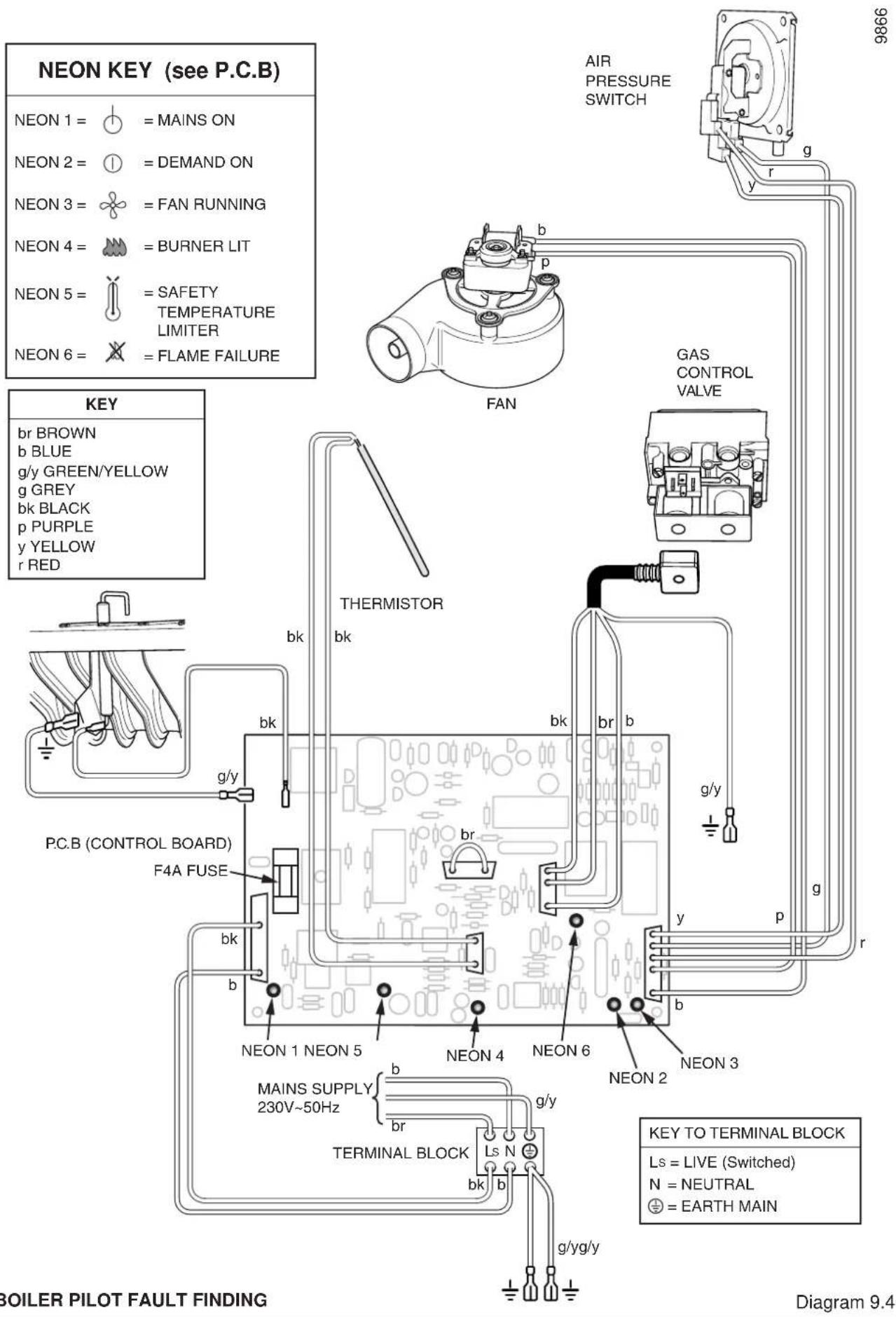
Refer to: Boiler Fault Finding, see diagram 9.2, Fault Finding Wiring Diagram, see diagram 9.3, Pictorial Wiring Diagram, see diagram 9.4.

![graph TD A["Is neon 1 lit?"] -->|YES| B["Is there 230V ac between Ls and N"] A -->|NO| C["Check power supply"] B -->|YES| D["Is neon 2 lit?"] B -->|NO| E["With electrical supply isolated disconnect the 2 way thermistor plug from the PCB. Check that there is a resistance between 14k - 2.5kOhms."] E -…](/content/2026/05/1051081/images/58f789adefa28ca0ee143e1eb8ab76b27baff229fa6cc39fb689b1f93ac4101b.jpg)
ELECTRICAL FAULT FINDING
Diagram 9.2
9 Fault Finding
9.2 Electrical Supply Failure
Failure of the electrical supply will cause the burner to go out. Operation will normally resume on the restoration of the electrical supply.
If the burner does not relight after an electrical supply failure and the reset neon on the control panel is lit, turn the burner temperature control to "0", wait 30 seconds, then fully clockwise to "Max." see diagram 9.1.
![graph TD A["MAINS SUPPLY 230v ~ 50Hz"] --> B["SL"] B --> C["bk"] C --> D["FUSE TYPE F4A"] D --> E["br"] E --> F["p"] F --> G["FAN"] G --> H["b"] H --> I["N"] I --> J["KEY"] J --> K["bk BLACK"] J --> L["br BROWN"] J --> M["b BLUE"] J --> N["p PURPLE"] J --> O["y YELLOW"] J --> P["gy GREY"] Q["SPARK E…](/content/2026/05/1051081/images/dc9e85a28dc7643835847cdbb3bf1930e615d6260a4a73153bcef7e6c64a102f.jpg)
Diagram 9.3
9 Fault Finding
10 Replacement of Parts
IMPORTANT NOTES
REMEMBER, When replacing a part on this appliance, use only spare parts that you can be assured conform to the safety and performance specification that we require. Do not use reconditioned or copy parts that have not been clearly authorised by Halstead Boilers Ltd.
Replacement of parts must only be carried out by a competent person.
Before removing or replacing any parts, turn off the gas supply at the gas service cock, see diagram 8.2 and isolate the electrical supply to the appliance.
Unless stated otherwise, all parts are replaced in the reverse order to removal.
After replacing any parts always test for gas soundness and if necessary carry out functional check of controls.
10.1 Electrical Thermistor
Remove front panel to gain access, see section 6.8.
Remove control box cover by undoing the four securing screws (two on control box, two on the heat shield) and lift off, see diagram 10.1.
Remove thermistor lead from retaining clip, located on the control box support bracket, see diagram 8.3.
Release strain relief grommet securing thermistor lead at the side of control box.
Disconnect the thermistor electrical plug from the control board (P.C.B) slightly bending back the retaining latch to allow withdrawal, see diagram 10.2.
Remove the retaining wire and withdraw the electrical thermistor from its phial, see diagram 10.3.
Draw the thermistor lead followed by the thermistor out though the control box case.
Re-assembly note. When fitting the thermistor make sure it is fully inserted into the phial, see diagram 10.3. Take care when re-threading retaining wire so as not to damage thermistor.
10.2 Control Board (P.C.B)
Remove front panel to gain access, see section 6.8.
Remove control box lid by undoing the four securing screws (two on control box, two on the heat shield) and lift off, see diagram 10.1.
Carefully pull the boiler temperature control knob away from the P.C.B.
Disconnect the electrical plugs from the control board (PCB) slightly bending back the retaining latches to allow withdrawal, see diagram 10.2.
Disconnect the ignition lead.
Carefully pull the board away from its supports bending back slightly the retaining latches.
When refitting refer to wiring diagram 9.4.
Take care when replacing the burner temperature control knob by supporting the potentiometer on the P.C.B.

ELECTRICAL PLUGS Diagram 10.2

Diagram 10.3


SOLENOID ASSEMBLY Diagram 10.4
10 Replacement of Parts
10.3 Electrode
Remove front panel to gain access, see section 6.8.
Refer to the relevant paragraphs of the servicing section to remove the burner from combustion chamber.
To remove the electrode, unscrew the retaining bracket, see diagram 8.13.
Take the electrode out from below and remove the ignition lead.
When removing and replacing the electrode take care not to damage it.
When refitting, check spark gap, see diagram 8.13.
10.4 Multifunctional Control
Remove front panel to gain access, see section 6.8.
Remove the electrical plug securing screw and disconnect the plug, see diagram 10.4.
Disconnect the gas cock, on the left hand side.
Support the multifunctional control, remove the four screws (2 long, 2 short) from the flanged connection at the right hand side.
Remove and discard the original "O" ring from the flanged connection and fit the new "O" ring supplied, into recess, before fitting the replacement multifunctional control.
After assembly test for gas soundness and purge in accordance with the current issue of BS6891.
10.5 Solenoid
Remove front panel to gain access, see section 6.8.
Remove the electrical plug from the multifunctional control and remove the securing screw and then the solenoid assembly, see diagram 10.4.
10.6 Burner
Refer to the relevant paragraphs of the servicing section to remove the burner from combustion chamber.
10.7 Injector
Refer to the relevant paragraphs of the servicing section to remove the burner from combustion chamber.
The injector can then be unscrewed from the manifold.
When replacing use a little jointing compound on the external thread only, to ensure a gas tight seal.
10.8 Air Pressure Switch
Remove front panel to gain access, see section 6.8.
Refer to the relevant paragraphs of the servicing section to remove the fan access door.
Remove the air pressure tube and electrical connections from the switch, release the securing screws and remove the switch, see diagram 10.5.
When fitting the replacement make sure that the air pressure tubes are fitted, as shown in diagram 10.5 and the electrical connections are made as shown in wiring diagram 9.4.
10.9 Fan
Remove front panel to gain access, see section 6.8.
Refer to the relevant paragraphs of the servicing section to remove the fan access door.
Remove the electrical connections and air pressure tube from the fan.
Note: Remove the electrical connections by pulling insulation boots only.
Undo the screw securing the fan to the flue hood and disengage fan from flue hood, see diagram 10.5.
When re-assembling, make sure that the air pressure tubes are fitted as before and that the fan duct engages fully into the flue duct extension piece.
The polarity of the electrical connections is not important.
10.10 Insulation
Refer to the relevant paragraphs of the servicing section to remove the burner from combustion chamber.
Sides
Undo the burner support bracket nuts and remove support bracket and insulation, see diagram 10.6.
Refit support bracket with new side insulation.
Rear
Bend forward rear insulation securing nibs, one on each side, to release insulation.
Fit new insulation and bend back securing nibs.


11 Spare Parts
11.1 Part Identification
The key number in diagram 11.1 and the first column of the list will help identify the spare part.
11.2 Ordering
When ordering any spare part please quote the part number and the description from the list together with the model name and serial number information from the data label.
The data label is positioned on the heat shield, see diagram 6.1.

Diagram 11.1
| Key No. | Part No. | Description | GC Part No. | |
| 1 | 200046 | 1752 Multifunctional control ***** | ||
| 2 | 227131 | Fan ***** | ||
| 3 | 227071 | Air pressure switch CFF40 ***** | ||
| 3 | 227070 | Air pressure switch CFF50 ***** | ||
| 3 | 227097 | Air pressure switch CFF60 ***** | ||
| 4 | 200046 | 1793 Electrical thermistor ***** | ||
| 5 | 202635 | Spark electrode ***** | ||
| 6 | 227098 | Fuse ***** | ||
| 7 | 200046 | 1714 Boiler temperature control knob ***** | ||
| 8 | K7218 | Injector - CFF40 | ***** | |
| 8 | 205729 | Injector - CFF50 | ***** | |
| 8 | 200046 | 1837 Injector - CFF60 | ***** | |
| 9 | 227030 | Control board | ***** | |
| 10 | 205658 Burner CFF40 | ***** | ||
| 10 | 205655 Burner CFF50, CFF60 | ***** |
Because of our constant endeavour for improvement, details may vary slightly from those shown in these instructions.


- INSTRUCTIONS FOR USE
- INSTALLATION AND SERVICING
- HALSTEAD
- IMPORTANT INFORMATION
- TESTING AND CERTIFICATION
- CE MARK
- INFORMATION FOR THE INSTALLER AND SERVICE ENGINEER
- SPARE PARTS
- MANUAL HANDLING GUIDANCE
- INTRODUCTION
- GAS SAFETY (INSTALLATION AND USE) REGULATIONS
- WARNINGS
- GAS LEAK OR FAULT
- CLEARANCES
- SHEET METAL PARTS
- CLEANING
- BOILERS INSTALLED IN A COMPARTMENT
- PROTECTION AGAINST FREEZING
- MAINTENANCE
- BOILER ELECTRICAL SUPPLY
- TO CONNECT AN ELECTRICAL PLUG
- TO TURN THE APPLIANCE ON
- TO TURN THE APPLIANCE OFF
- GENERAL DATA
- IMPORTANT NOTICE
- TECHNICAL DATA
- RANGE RATING
- STATUTORY REQUIREMENTS
- B.S.I CERTIFICATION
- GAS SUPPLY
- ELECTRICAL
- CONDENSATE DRAIN
- BOILER LOCATION
- HEATING SYSTEM CONTROLS
- WATER SYSTEMS
- WATER PRESSURE HEAD
- INHIBITOR
- GRAVITY DOMESTIC AND PUMPED HEATING
- PUMPED HEATING AND HOT WATER
- CIRCULATION PUMP
- CYLINDER
- SAFETY VALVE
- DRAINING TAP
- THERMOSTATIC RADIATOR VALVES
- FLUE AND VENTILATION
- IMPORTANT NOTES
- FLUE GUIDELINES
- EXISTING CHIMNEY
- NEW CHIMNEY
- TIMBER FRAME BUILDINGS
- VENTILATION FOR BOILER INSTALLED IN A ROOM OR SPACE
- VENTILATION FOR BOILERS INSTALLED IN A COMPARTMENT
- VENTILATION FOR BOILERS INSTALLED IN A CUPBOARD
- EXTRACT FANS
- INSTALLATION
- GENERAL INSTALLATION NOTES
- UNPACKING
- WATER CONNECTIONS - GRAVITY DOMESTIC AND PUMPED HEATING
- WATER CONNECTIONS - FULLY PUMPED SYSTEMS
- PIPEWORK
- CASING BRACKETS
- SIDE CASINGS
- SIDE IN-FILL PANEL (IF REQUIRED)
- NOTE
- FLUE / BOILER CONNECTION
- FLUE CONNECTION
- WATER & GAS CONNECTIONS
- CONDENSATE DRAIN CONNECTION (IF APPLICABLE)
- TOP CASING
- ELECTRICAL WIRING
- CONTROL BOX ACCESS
- ELECTRICAL CONNECTIONS
- PUMP CONNECTION
- TESTING - ELECTRICAL
- COMMISSIONING
- IMPORTANT NOTE
- ALL SYSTEMS
- INITIAL LIGHTING AND TESTING
- TESTING - GAS
- TESTING - ALL WATER SYSTEMS
- OPEN VENTED SYSTEM
- ADJUSTMENT - FULLY PUMPED OPEN VENTED SYSTEM
- COMPLETION
- INSTRUCTIONS TO THE USER
- SERVICING
- PRODUCTS OF COMBUSTION CHECK
- ACCESS
- BOILER FLUEWAYS
- BURNER AND INJECTOR
- SERVICE CHECKS
- FAULT FINDING
- ELECTRICAL SUPPLY FAILURE
- REPLACEMENT OF PARTS
- ELECTRICAL THERMISTOR
- CONTROL BOARD (P.C.B)
- ELECTRODE
- MULTIFUNCTIONAL CONTROL
- SOLENOID
- BURNER
- INJECTOR
- AIR PRESSURE SWITCH
- FAN
- INSULATION
- SIDES
- REAR
- PART IDENTIFICATION
- ORDERING
Brand : Halstead
Model : Buckingham 4 CFF40
Category : Water heaters and boilers