EWH-E3883AC(SG) - Water heater Elba - Free user manual and instructions
Find the device manual for free EWH-E3883AC(SG) Elba in PDF.


| Product Type | Instantaneous Electric Water Heater (Open System) |
| Model | Elba EWH-E3883AC(SG) (AC Pump Version) |
| Dimensions (H x W x D) | 440 mm x 190 mm x 75 mm |
| Net Weight (Pump Model) | 2.0 kg |
| Power Supply | 220-240 V~, 50/60 Hz |
| Rated Power | 3.6 kW at 240 V (other ratings available - see electrical loading table) |
| Current Rating | 15.0 A at 240 V (3.6 kW) |
| Water Connection | 15.0 mm (1/2" BSP) inlet and outlet |
| Minimum Water Flow Rate | 2 L/min |
| Minimum Water Pressure | 0.2 bar (20 kPa) |
| Maximum Water Pressure | 4 bar (0.4 MPa) |
| Degree of Protection | IP25 (splash-proof) |
| Safety Features | Built-in ELCB (15 mA sensitivity), Thermal Cut-Off, Flow Switch |
| Pump Type | AC Pump (boosts water flow) |
| Temperature Control | Rotary knob from OFF to MAX |
| LED Indicators | POWER and HEATER LEDs |
| Water Saver Feature | Removable water saver chips in hand shower and rain shower head (optional) |
| Installation Requirements | Must be earthed; professional installation required; do not reverse INLET/OUTLET |
| Maintenance | Clean filter regularly; wipe with damp cloth and mild detergent; do not use solvents |
| Monthly Check | Test ELCB by pressing TEST button; should trip and reset |
| Compatible Accessories | Rain shower set (optional), flexible hose, stop valve |
Frequently Asked Questions - EWH-E3883AC(SG) Elba
User questions about EWH-E3883AC(SG) Elba
0 question about this device. Answer the ones you know or ask your own.
Ask a new question about this device
Download the instructions for your Water heater in PDF format for free! Find your manual EWH-E3883AC(SG) - Elba and take your electronic device back in hand. On this page are published all the documents necessary for the use of your device. EWH-E3883AC(SG) by Elba.
USER MANUAL EWH-E3883AC(SG) Elba
Looks Good. Works Even Better.
FIOTTO Series
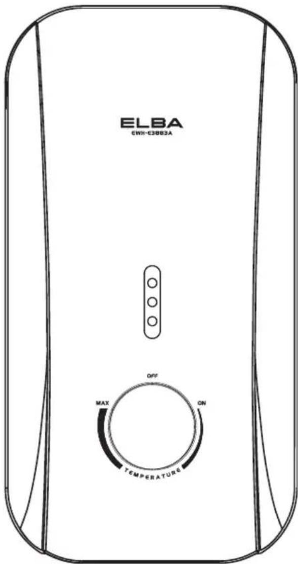
User Manual
Please read this manual thoroughly and understand the content before use.

SAFETY PRECAUTION
- Do not install reverse INLET & OUTLET of heater.
- Do not install the heater where there is consistent spray directly over the unit.
- Do not connect the OUTLET to any tap or fitting that is not recommended by the manufacturer.
- Do not block the heater OUTLET in any way.
- Do not attempt to repair the heater without qualified technician.
- Do not leave children, elderly or disable person alone in shower.
- Engage qualified electrician for installation.
- Test water temperature with hand before using the shower.
- Check the ELCB once a month (please refer to the Test Run of Heater) and consult professional for repair if there is any malfunction.
- Metallic / chromed flexible hose and conductive control valve shall not be used.
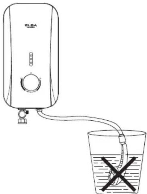
- Do not leave the hand shower idle in the pail.
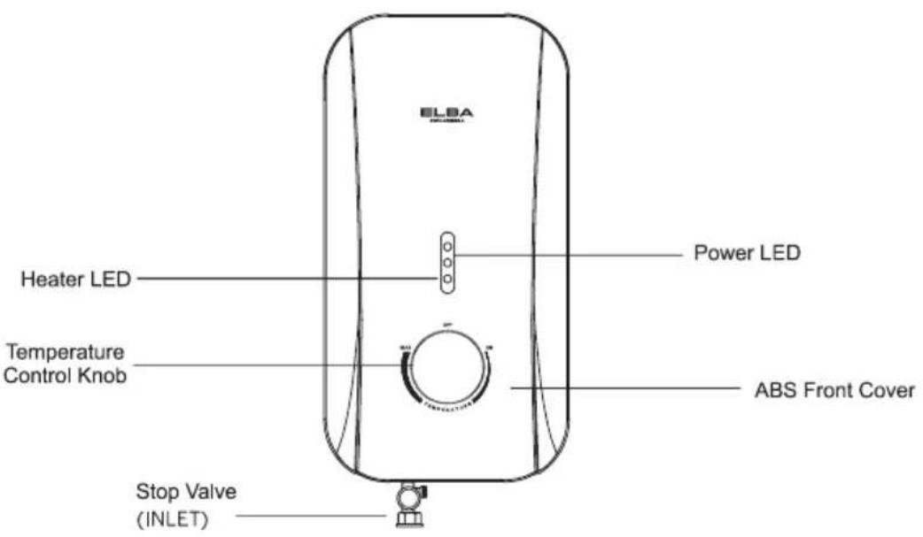
1. WATER HEATER PARTS IDENTIFICATION
EXTERNAL PARTS IDENTIFICATION
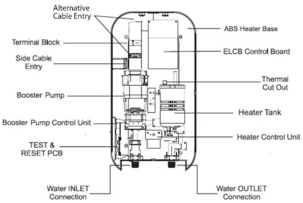
INTERNAL PARTS IDENTIFICATION
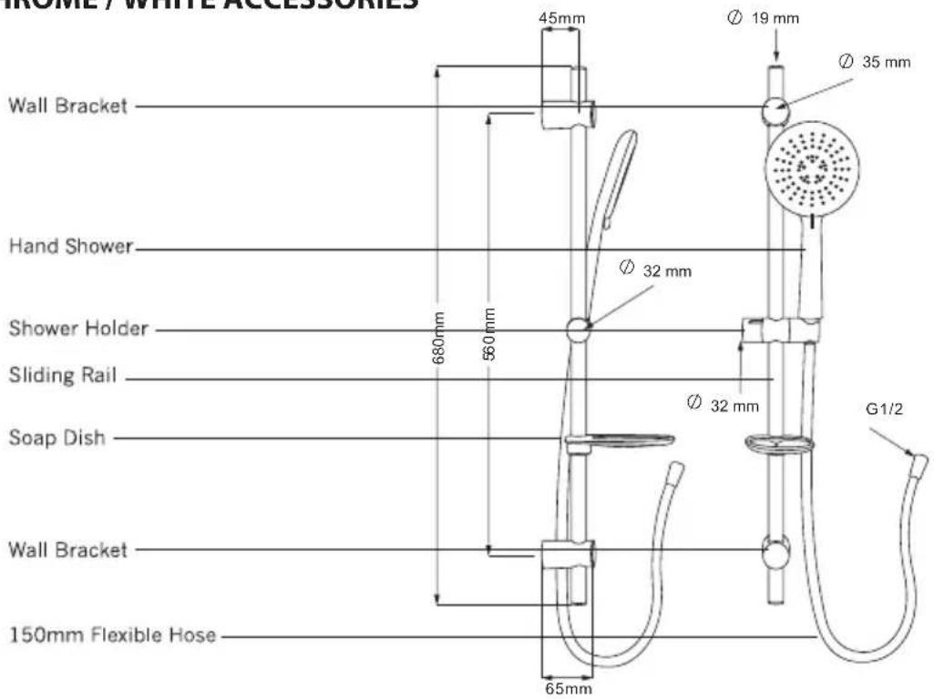
- CHROME / WHITE ACCESSORIES
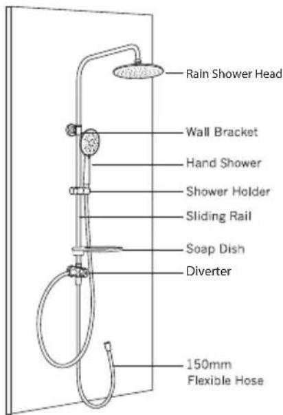
2. RAIN SHOWER SET
(Optional Features)
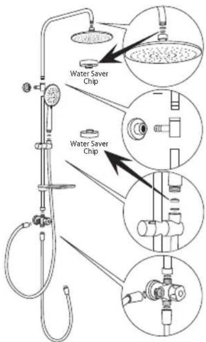
STEP 1
There is two Water Saver Chips located under the hand shower and on top of the rain shower head.
Water Saver Chip
A chip that helps you save water up tp 50%!
ALERT
You may remove the two water saver chips if prefer stronger water pressure. Please be reminded that this is up to personal preference.
STEP 2
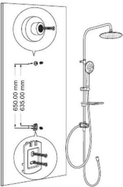
Do marking for the location of the lower square and upper round bracket. Install the bracket holders on the wall.
Assemble the upper tube with rain shower and lower tube with divider.
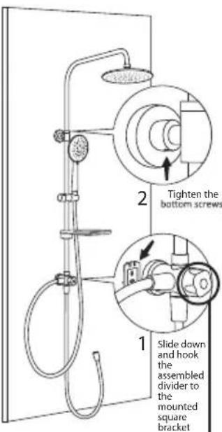
Slide down and hook the assembled divider to the mounted square bracket.
Tighten the screws and make sure all joints are completely connected to avoid leakage.
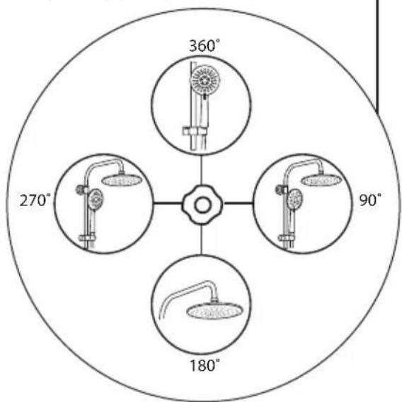
360 Degrees 3-in -1 Rotation Diverter
2. GENERAL INFORMATION
INSTALLATION

CAUTION: THIS APPLIANCE MUST BE EARTHED.
- All the plumbing work should be completed before proceeding to electrical wiring connection. (Table 1)
- Installation must be carried out by a qualified electrician with close reference to the operation manual and in compliance with the local regulations.
- The unit works at minimum water flow rate of 2 litre/min, which then would trigger the built-in pump (only for pump model), boosting a stronger shower spray.
- The built-in electronic Earth Leakage Circuit Breaker (ELCB) would cut-off the power supply to the heater in the event of current leakage of as low as 15mA. (Refer to AUTO INSPECT ALARM Indication - optional)
- The Thermal Cut-Off would automatically shut off the power supply shall there is any abnormal rise of showering temperature.
- The unit only operates when there is sufficient water flow to trigger the flow switch.
- Electrical loading Table 1:
| Voltage (Vac) | Power (kW) | Amperes (A) | Recommended Conductor Size (csa) | MCB/ Fuse (A) | ON/OFF Switch (A) | ||
| mm^2 | Conduit Cable | Flexible Cable | |||||
| 220 - 50/60Hz | 3.5 | 16.0 | 2.5 | 7/0.67mm | 50/0.25 | 20 | 20 |
| 4.5 | 20.5 | 2.5 | 7/0.67mm | 56/0.30 | 25 | 25 | |
| 5.5 | 25.0 | 4.0 | 7/0.85mm | 56/0.30 | 32 | 32 | |
| 6.0 | 27.3 | 4.0 | 7/0.85mm | 56/0.30 | 32 | 32 | |
| 6.5 | 29.6 | 4.0 | 7/0.85mm | 84/0.30 | 32 | 32 | |
| 7.5 | 34.1 | 6.0 | 7/1.04mm | 84/0.30 | 40 | 40 | |
| 8.0 | 36.4 | 6.0 | 7/1.04mm | 84/0.30 | 40 | 40 | |
| 230 - 50/60Hz | 3.5 | 15.2 | 2.5 | 7/0.67mm | 50/0.25 | 20 | 20 |
| 5.5 | 24.0 | 4.0 | 7/0.85mm | 56/0.30 | 32 | 32 | |
| 6.6 | 28.7 | 4.0 | 7/0.85mm | 56/0.30 | 32 | 32 | |
| 8.8 | 28.3 | 6.0 | 7/1.04mm | 84/0.30 | 40 | 40 | |
| 240 - 50/60Hz | 3.6 | 15.0 | 2.5 | 7/0.67mm | 50/0.25 | 20 | 20 |
| 4.2 | 17.5 | 2.5 | 7/0.67mm | 50/0.25 | 20 | 20 | |
| 7.7 | 32.1 | 6.0 | 7/1.04mm | 84/0.30 | 40 | 40 | |
| 9.0 | 37.5 | 6.0 | 7/1.04mm | 84/0.30 | 40 | 40 | |
3. INSTALLATION PROCEDURES
- All the plumbing works should be completed before proceeding to electrical wiring connection.
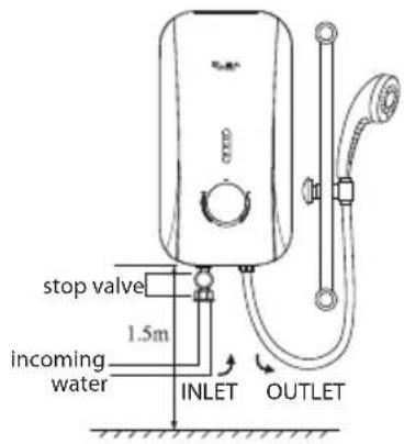
- INLET and OUTLET connection of the heater unit should not be reversed, with stop valve installed on INLET. (Diagram 1)
- It is recommended that the unit should be mounted above 1.5m or 5-feet above the floor to bottom of the heater. (Diagram 1)
-
Mark mounting position (Diagram 2)
-
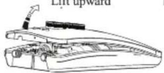
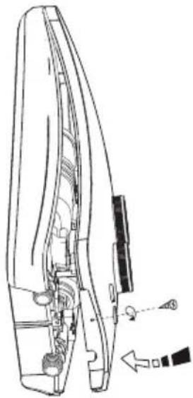
Remove screw at the bottom of the heater
• Lift the plastic cover upward
• Mark mounting position on the wall
• Drill the holes with 5.0mm diameter drill bit
• Install the unit to the wall with plug -
Heater INLET and OUTLET Connection (Diagram 3)
a) Connect the stop valve to INLET, and be sure to put a gasket to prevent water leakage,
b) Connect the piping from the stop valve to incoming water supply. If necessary, make use of sealing tape for the connection to prevent water leakage.
c) Connect flexible hose to heater OUTLET. Turn on the water mains to drain out all the plumbing dirt and fill up the heater tank. Then, connect the flexible hose to the hand shower.
(Note: This step will prevent damage to the heating element).
Lift upward
Diagram 1
natural_image
Line drawing of a mechanical component with an upward arrow and label 'Lift upward' (no other text or symbols)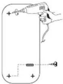
natural_image
Simple line drawing of a hand holding a tool with a small object nearby (no text or symbols)Diagram 2

SAFETY PRECAUTION
Do not install reverse INLET and OUTLET of heater
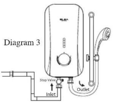

correct installation inlet - outlet reve
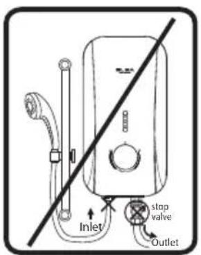

(wrong installation)
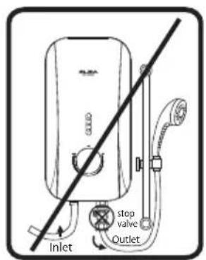

stop valve reverse (wrong installation)
6. Electrical Connection
IMPORTANT NOTE!
SWITCH OFF THE MAIN SUPPLY BEFORE ELECTRICAL WORK
a) Insert electrical cable through the rubber grommet as shown.
b) Connect the cable to the terminal block and fully tighten them as the following:-
• Red or Brown.....Live (L)
- Black or Blue....Neutral (N)
• Green or Green/Yellow....Earth ⊕
c) Restore the cover and secure screw at the bottom. (Diagram 4)
d) Align the knob, from 'OFF' position to 'MAX' and return to 'OFF' mark as shown (Diagram 5)
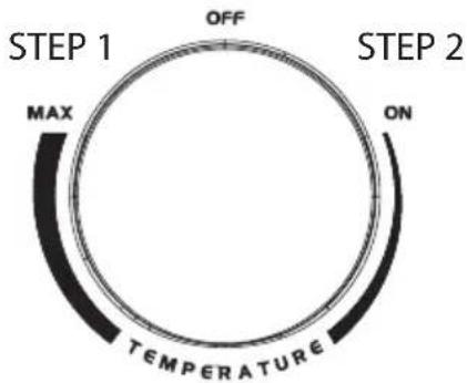
Diagram 5
Restore cover
natural_image
Technical line drawing of a car door handle and side panel (no text or symbols)Diagram 4
Test Run Of Heater:
a) Turn on the stop valve and water should spray out from the shower head.
b) Switch on the main power supply ("POWER" LED would light up).
c) Turn on the Temperature Control Knob and 'HEATER' LED would light up. The water should be warmed in a few seconds.
d) Turn on the Pump Control Knob clockwise to accelerate water flow. (For Pump model only)
e) Test the ELCB by pressing 'TEST' button. The unit should be tripped. 'POWER' and 'HEATER' LEDs would light off.
f) Press 'RESET' button. The unit should resume to normal condition.
g) The heater is now ready for use.
1 Switch on the main power supply, the 'POWER' LED would light up.
2. Turn on the water supply at the stop valve.
3. Turn on the Temperature Control Knob. The 'HEATER' LED would light up and the water temperature will be increased accordingly as the knob being turned clockwise from 'ON' to 'MAX'.
4. For normal cold shower, just turn the Temperature Control Knob to 'OFF' position.
5 Switch off the power supply when not in use.
5. GENERAL MAINTENANCE
DO NOT USE THINNER, ALCOHOL OR PETROL
You may clean the heater with a damp cloth and mild detergent but do not use thinner, alcohol, petrol or any other organic solution.
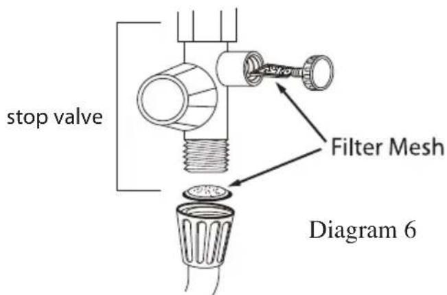
CLEAN FILTER REGULARLY (Diagram 6)
a) Remove the filter mesh at the stop valve (for filter type only) by turning the knob filter counter clockwise direction and pull out the knob (Diagram 6). Flush it with water to remove any trapped sediments. Install the knob filter back to its original position.

6. TECHNICAL SPECIFICATION
| Electrical loading | 3.6kW 240V 50Hz |
| Other Range | Please refer Electrical loading Table |
| ELCB sensitivity | 15 mA |
| Operating Condition | Open System (Open Outlet) |
| Water Connection | ∅ 15.0mm (1/2” BSP) |
| Degree of Protection | IP25 |
| Minimum Water Flow Rate | 2 litre/min |
| Minimum Water Pressure | 0.2 bar (20kPa / 2.9psi) |
| Maximum Water Pressure | 4 bar (0.4MPa / 58psi) |
| Heater Dimension (mm) | 440(H) x 190(W) x 75(D) |
| Heater Nett Weight | Non pump 1.3kgInverter Silent Pump 1.8kgAC Pump 2.0kg |
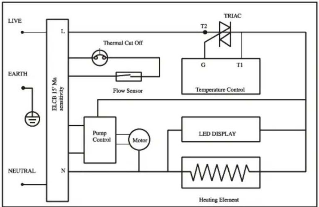
7. SCHEMATIC WIRING DIAGRAM
INVERTER SILENT PUMP (EWHR-E3885DC)
flowchart
graph TD
    A["LIVE"] --> B["ELCB 15° Ma sensitivity"]
    C["EARTH"] --> B
    D["NEUTRAL"] --> B
    B --> E["L"]
    E --> F["Thermal Cut Off"]
    F --> G["Flow Sensor"]
    G --> H["Pump Control"]
    H --> I["Motor"]
    I --> J["LED DISPLAY"]
    J --> K["Heating Element"]
    L["TRIAC"] --> M["G"]
    M --> N["T1"]
    N --> O["T2"]
    P["Temperature Control"] --> Q["G"]
    Q --> R["T1"]
AC PUMP (EWH-E3883AC)
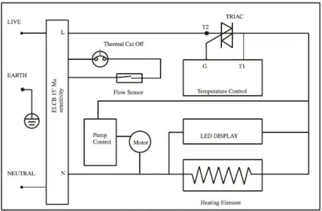
flowchart
graph TD
    A["LIVE"] --> B["ELCB 15° Ma sensitivity"]
    C["EARTH"] --> B
    D["NEUTRAL"] --> B
    B --> E["L"]
    E --> F["Thermal Cut Off"]
    F --> G["Flow Sensor"]
    G --> H["Pump Control"]
    H --> I["Motor"]
    I --> J["LED DISPLAY"]
    J --> K["Heating Element"]
    L["TRIAC"] --> M["G"]
    M --> N["T1"]
    N --> O["Temperature Control"]
    P["T2"] --> Q["TRIAC"]
    style A fill:#f9f,stroke:#333
    style C fill:#f9f,stroke:#333
    style D fill:#f9f,stroke:#333
    style L fill:#ccf,stroke:#333
    style M fill:#ccf,stroke:#333
    style N fill:#ccf,stroke:#333
    style O fill:#ccf,stroke:#333
NON -PUMP (EWH-E3881)
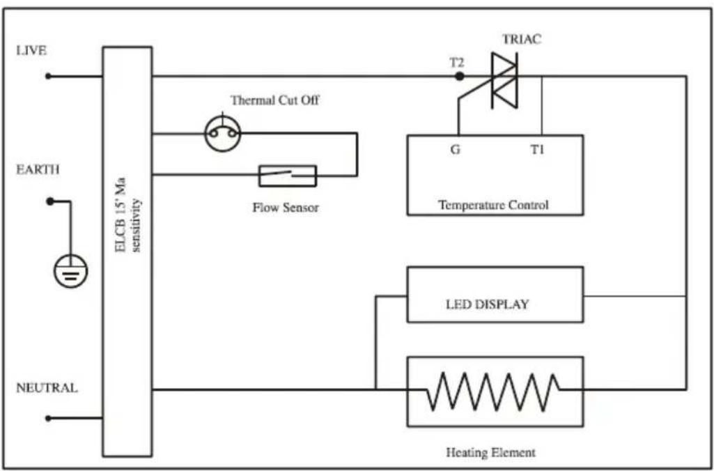
flowchart
graph TD
    A["LIVE"] --> B["ELCB 15° Ma sensitivity"]
    C["EARTH"] --> B
    D["NEUTRAL"] --> B
    B --> E["Thermal Cut Off"]
    E --> F["Flow Sensor"]
    F --> G["TRIAC"]
    G --> H["G"]
    G --> I["T1"]
    H --> J["Temperature Control"]
    I --> J
    J --> K["LED DISPLAY"]
    K --> L["Heating Element"]
    L --> M["Refrigerator"]
- FIOTTO Series
- SAFETY PRECAUTION
- WATER HEATER PARTS IDENTIFICATION
- RAIN SHOWER SET
- STEP 1
- Water Saver Chip
- ALERT
- STEP 2
- GENERAL INFORMATION
- INSTALLATION
- CAUTION: THIS APPLIANCE MUST BE EARTHED.
- INSTALLATION PROCEDURES
- Electrical Connection
- IMPORTANT NOTE!
- SWITCH OFF THE MAIN SUPPLY BEFORE ELECTRICAL WORK
- Test Run Of Heater:
- GENERAL MAINTENANCE
- DO NOT USE THINNER, ALCOHOL OR PETROL
- CLEAN FILTER REGULARLY (Diagram 6)
- TECHNICAL SPECIFICATION
- SCHEMATIC WIRING DIAGRAM
Brand : Elba
Model : EWH-E3883AC(SG)
Category : Water heater