
CMP5000WXU-511 - Screen HITACHI - Free user manual and instructions
Find the device manual for free CMP5000WXU-511 HITACHI in PDF.


| Product Type | Color Plasma Display Monitor |
| Model | CMP5000WXU (CMP5000WXU-511) |
| Panel Size | 50 inches (diagonal) |
| Resolution | 1280 x 768 pixels |
| Dimensions (W x H x D) | 1218 mm x 714 mm x 98 mm (47-31/32" x 28-1/8" x 3-7/8") |
| Weight | 38.9 kg (85 lbs 12 oz) |
| Power Supply | AC 100-120 V, 50/60 Hz, 3.8 - 3.1 A |
| Power Consumption | 380 W (typical), Standby: 1 W |
| Supported Computer Resolutions | VGA (640x400, 640x480) to XGA (1024x768), SXGA (1280x1024), UXGA (1600x1200) compressed |
| Input Terminals | INPUT1 (Mini D-sub 15-pin), INPUT2 (BNC x5), Audio Input (Stereo mini jack) |
| Output Terminals | OUTPUT (INPUT1) (Mini D-sub 15-pin), Audio Output (Stereo mini jack), Speaker terminals (8-16 Ω) |
| Screen Size Modes | DOT-BY-DOT, 4:3, FULL, PARTIAL |
| Special Features | AUTO SETUP, POINT ZOOM (1.5x to 4x), Power Control (Standard/Mode1/Mode2), Auto Function (input switching), Power Management, Auto Power Off |
| Safety Features | Thermal alert, fan failure detection, overcurrent protection, condensation detection |
| Cooling | Internal fan (auto speed control, operates above 35°C) |
| Accessories Included | Power cord, remote control (with batteries), speed clamps (2), bead bands (2), user manual |
| Optional Accessories | Table top stand, wall installation unit, speaker system, video card (CMPAV05) |
| Panel Protection | Screen saver activates after ~3 minutes of still image; power control helps prevent burn-in |
| Compliance | FCC Class B, ENERGY STAR partner |
Frequently Asked Questions - CMP5000WXU-511 HITACHI
User questions about CMP5000WXU-511 HITACHI
0 question about this device. Answer the ones you know or ask your own.
Ask a new question about this device
Download the instructions for your Screen in PDF format for free! Find your manual CMP5000WXU-511 - HITACHI and take your electronic device back in hand. On this page are published all the documents necessary for the use of your device. CMP5000WXU-511 by HITACHI.
USER MANUAL CMP5000WXU-511 HITACHI
Color Plasma Display Monitor
Model
CMP5000WXU
CMP5000WXJ
USER'S MANUAL
MANUEL UTILISATEUR
取扱説明書
READ THE INSTRUCTIONS INSIDE CAREFULLY. KEEP THIS USER MANUAL FOR FUTURE REFERENCE.
For future reference, record the serial number of your monitor.
SERIAL NO.
The serial number is located on the rear of the monitor.
Contents related to system specifications, power requirements, accessories, and other information differ with respect to the country where this unit is purchased. For customers living in the U.S.A. or Canada, please use and refer to the instructions written in either English or French. For customers in Japan, please use and refer to the instructions written in Japanese.
This unit has been designed for use as a computer display monitor. The optional video card is required if you wish to view other video signals on the monitor. For details consult your local retail dealer.
Français
This monitor is designed to be safe to use. However, fire or serious injury may occur unless you use this monitor in the proper way. Please follow the instructions shown below in order to avoid injury.

Keep the safety guideline
Do not use the monitor if it fails
If you find something unusual,
* If smoke comes out,
* If there is a strange smell,
* If water enters the case,
* If you drop the monitor or damage the cabinet,

(1) Turn off the monitor
(2) Disconnect the power plug from the mains
(3) Request repair
Warning and Caution are indicated in this guide and monitor itself.

WARNING
Fire or electric shock may cause death or serious injury unless you follow the instruction.

CAUTION
Electric shock or other accidents may cause serious injury or damage of your properties.

WARNING
Fire or electric shock may cause death or serious injury unless you follow the instruction below.
- If something smells strange or smoke comes from the monitor:
Turn off the monitor and disconnect the power plug from the mains immediately.
Contact service center after confirming that the smoking has stopped.
If you continue to operate the monitor with such abnormal condition, it may cause fire or you may receive an electric shock.
- Do not drop water or a foreign substance on to the monitor.
If you drop water or a foreign substance on to the monitor, it may cause fire or an electric shock.
If it happens turn off the monitor and disconnect the power plug from the mains and ask service center for instruction.
- Do not put the monitor on an unstable place.
If you put the monitor on an uneven or unstable place, it may fall down and you may be injured.
Put the monitor on a flat surface strong enough to take the weight.
- Do not apply shock to the monitor.
- Do not use monitor if glass is broken or damaged.
If there is no picture appearance, broken glass, smoking or something smells after applying shock to the monitor, turn off the monitor and disconnect the power plug from the mains immediately. Then, call the service center.
If you continue to operate the monitor with such abnormal conditions, it may cause fire or you may receive an electric shock.
- Do not disassemble or modify the monitor.
There is high voltage portion inside of the monitor. Disassembling or modification of the monitor may cause fire or electric shock.
- Do not use the monitor in wet environment.
If you use the monitor in a wet place such as bath or shower room, it may cause fire or electric shock. Using the monitor beside a window when snowing or raining or by a seaside are not recommended.
- Do not damage or modify the power cord.
If you put something heavy on the power cord or pull, squeeze, heat the cord, it may be damaged and it may cause fire or electric shock. If the power cord is damaged, call service center.
SAFETY GUIDELINES(continued)
WARNING
Fire or electric shock may cause death or serious injury unless you follow the instruction.
- The enclosed power cord must be used!
Failure to do so may cause electric shock hazard or fire hazard. In USA/Canada, use a UL LISTED/CSA LABELLED or CERTIFIED power cord set meeting the following specifications: Rating: min. 125V, 6A, Length: max. 3.0m, Type: SVT or SJT Plug type: NEMA 5-15P figure, Parallel blade, Grounding type
- Be careful of power cord connection!
Before inserting the plug of the power cord into a socket of the correct voltage, check that the connection portion of the power cord is clean (with no dust). Then, insert the plug of power cord into the socket firmly, otherwise it may cause electric shock or fire hazard.
- Do not touch the power plug when lightning is close to you.
You may receive an electric shock.
- Do not touch the power plug with wet hands.
You may receive an electric shock.
- Do not obstruct a ventilation hole.
If you obstruct a ventilation hole during the operation of the monitor or just after switching off the power, it may cause a fire or electric shock due to heating up the monitor.
- Do not put the monitor screen side up.
- Do not put the monitor on a shelf or in a cabinet without adequate ventilation of 4 inches top, sides, bottom and rear.
- Do not put the monitor on a carpet or mattress.
- Do not cover the monitor with a cloth.
CAUTION
Electric shock or other accidents may cause serious injury or damage to your property.
- Disconnect the power plug from the mains when you move the monitor.
Moving the monitor without disconnecting the power plug from the mains may damage the cord and cause a fire or electric shock. You are advised to move the monitor with two persons. Handle with care when you move the monitor, particularly take care of glass screen.
- When you disconnect the power plug.
You have to grasp the power plug itself, do not pull the power cord. If you pull the power cord, you may damage it and it may cause a fire or an electric shock. Do not touch the power plug just after disconnecting it from the mains or you may receive electric shock.
- Disconnect the power plug from the mains when you don't use the monitor for a long time.
This is for your safety.
- Do not put the monitor in atmosphere with soot, steam, high humidity, and dust.
It may cause a fire or electric shock.
- Do not put the monitor in high temperature atmosphere.
Do not put the monitor in the place exposed to the direct rays of the sun for a long period of time. Heat may cause a fire, transformation, or melting of the monitor.
- Do not put things on the monitor.
Do not put things on the monitor or give some shock to the monitor. The monitor may fall down or drop from a desk. And it may cause injury.
CAUTION
You may have serious injury or your property may be damaged unless you follow the instruction below.
- Do not coil or wind the power cord.
This may cause excessive heat resulting in a fire.
- Remove the power cord for complete isolation!
For complete isolation from the mains, remove the power cord from the monitor or from the wall socket.
PRECAUTIONS
• Installation environment
Do not obstruct a ventilation hole.
Do not put the monitor on carpet or blanket, or near a curtain which has a possibility of obstructing a ventilation hole of the monitor.
Do not put the monitor in the following places.
- Hot places such as near heater, place exposed to the direct rays of the sun.
- A place where the temperature is widely changing.
- Places with soot, dust or high humidity.
- Poor air ventilation place.
- Place near fire.
- A wet place such as bathroom, or shower room.
- Place where you can trip over it.
- Always vibrating or strongly vibrating places.
• Distorted or unstable places.
• How to view the monitor.
If you use the monitor in too dark a room, your eyes may become tired.
Please use it in a reasonably bright room.
Avoid direct rays of the sun to the screen in order to prevent eye fatigue.
Your eyes will get fatigued after viewing the monitor for long period of time.
Relax your eyes by viewing away from the monitor from time to time.
Please watch the monitor in downward direction.
• Note on image retention
The plasma monitor illuminates phosphor to display images. The phosphor has a finite illumination life. After extended periods of illumination, the brightness of the phosphor would be degraded to such extent that still images would image retention that part of the screen as grayed-out images.
Tips to prevent such image retention are:
- Do not display images having sharp brightness differences or high-contrast images, such as monochrome characters and graphic patterns, for long.
- Do not leave stationary images appearing for long, but try to refresh them at appropriate intervals of time.
- Turn down the contrast and brightness controls.
• How to clean the monitor.
Before cleaning the monitor, turn off the monitor and disconnect the power plug from the mains.
When cleaning the monitor, do not spray directly the screen or cabinet with cleaner.
Use a clean, dust free, dry and soft cloth. If it is not enough, then use a cloth with non-alcoholic or non-ammonia detergent.
Do not rub the surface of the screen with ball-point-pen or screw-driver etc.
• Prevention of an obstacle to Radio receivers
This monitor has been designed pursuant to the FCC class B Rules (see page IV). This is to prevent a problem to Radio receivers.
- Keep the monitor away from Radio.
- Adjust Radio antennas in order for the monitor not to receive interference.
- The antenna cable of Radio should be kept away from the monitor.
- Use a coaxial cable for antenna.
You can check if this monitor influences Radio receivers by turning off all other equipment other than the monitor.
If you find a problem receiving Radio when using the monitor, check the instructions mentioned above.
• Precautions for the monitor
- Confirm the connector is fixed tightly when the signal cable is connected.
Also confirm the screws on the connector are tightened.
- Plug the power cord of the monitor into a different socket from that for other equipment, such as Radio etc..
- Use a plug with ground terminal and make sure that it connects to the ground.
• Precaution during transportation
Please pay attention when you transport this monitor because it is heavy.
Furthermore, use the original carton box and its packaging materials when the monitor is transported.
Failure to transport the monitor in any carton except the original carton may result in damage to the monitor.
Save the original carton box and all packing material.
SAFETY GUIDELINES(continued)
• FCC (Federal Communications Commission) STATEMENT WARNING
For model CMP5000WXU (Plasma Display)
CMPAV05 (Video Card)
WARNING : This equipment has been tested and found to comply with the limits for a Class B digital device, pursuant to Part 15 of the FCC Rules. These limits are designed to provide reasonable protection against harmful interference in a residential installation. This equipment generates, uses, and can radiate radio frequency energy and, if not installed and used in accordance with the instructions, may cause harmful interference to radio communications. However, there is no guarantee that interference will not occur in a particular installation. If this equipment does cause harmful interference to radio or television reception, which can be determined by turning the equipment off and on, the user is encouraged to try to correct the interference by one or more of the following measures:
- Reorient or relocate the receiving antenna.
- Increase the separation between the equipment and receiver.
- Connect the equipment into an outlet on a circuit different from that to which the receive is connected.
- Consult the dealer or an experienced radio / TV technician for help.
Instructions to Users : This equipment complies with the requirements of FCC (Federal Communication Commission) regulations, provided that following conditions are met.
Video inputs: The input signal amplitude must not exceed the specified level.
CAUTION : Changes or modifications not expressly approved by the party responsible for compliance could void the user's authority to operate the equipment.
Declaration of Conformity
According to 47CFR, Part 2 and 15 for
Class B Personal Computers and
Peripherals; and / or
CPU Boards and Power Supplies used
with Class B Personal Computers:
We: Hitachi America, Ltd. Computer Division
Located at: 2000 Sierra Point Parkway, Brisbane, CA 94005-1835, U.S.A.
Telephone: 1-800-HITACHI
Declare under sole responsibility that the product identified herein, complies with 47CFR Part 2 and 15 of the FCC rules as a Class B digital device. Each product marketed, is identical to the representative unit tested and found to be compliant with the standards. Records maintained continue to reflect the equipment being produced can be expected to be within the variation accepted, due to quantity production and testing on a statistical basis as required by 47CFR § 2.909. Operation is subject to the following two conditions: (1) This device may not cause harmful interference, and (2) This device must accept any interference received, including interference that may cause undesired operation. The above named party is responsible for ensuring that the equipment complies with the standards of 47CFR § 1 5.101 to 15.109.
Trade name: Plasma Display Monitor with Video Card
Model Number: CMP5000WXU (Plasma Display)
CMPAV05 (Video Card)
USER'S MANUAL
Thank you very much for purchasing the HITACHI Plasma Display Monitor.
Before using your monitor, please carefully read the "SAFETY GUIDELINES" and this "USER'S MANUAL" so you will know how to operate the monitor properly. Keep this manual in a safe place. You will find it useful in the future.
Notes on Installation Work:
This product is marketed assuming that it is installed by qualified personnel with enough skill and competence. Always have an installation specialist or your dealer install and set up the product. HITACHI cannot assume liabilities for damage caused by mistake in installation or mounting, misuse, modification or a natural disaster.
Note for Dealers:
After installation, be sure to deliver this manual to the customer and explain to the customer how to handle the product.
Features
● Introduces newly developed 50" XGA Wide Plasma Panel
The new high-precision XGA 50" wide plasma panel pushes the envelope of previous high-luminance panels, producing brighter, clearer images with higher contrast.
●Newly developed full screen filter produces clear, high-contrast images even in a lighted room.
The new full screen filter suppresses surface reflections to a minimum, producing clear, high-contrast images even in lighted locations. Unnecessary frequency components of RGB signals are also cut, greatly enhancing color reproduction.
●Supports wide range of computer signal formats
Direct display of computer signals is supported in resolutions from 640x400 and 640x480 (VGA) to 1024x768 (XGA) and 1280x768; computer signals with resolutions of 1280x1024 (SXGA) and 1600x1200 (UXGA) are supported in compressed display format. Screen aspect ratios include DOT-BY-DOT, 4:3, FULL, and PARTIAL*1
* 1. Operation of screen aspect ratios and screen size differ depending on the input signal.
●Free Installation Configuration Broader installation possibilities with thinner, lighter, high-endurance design.
While producing a large 50" screen image, the display is only 98mm thick, and weighs in at only 38.9 kg. On the other hand, the efficient heat-radiating design greatly improves environmental operating conditions. The thinner, lighter design, coupled to high-endurance construction greatly broadens the range of possible installation locations and styles.
●High reliability for commercial applications
The is provided with features giving it high dependability in commercial applications, including the ability to suppress peak luminance in accordance with the viewing program, and to change the cooling fan's speed in accordance with changes in operating environment. Such features provide safety and high-endurance under conditions of commercial use.
●Improved usability
User convenience has been improved by the inclusion of features making the display even more compatible with your computer. Some of these include the one-touch screen adjustment AUTO SETUP function for computer connections, and the POINT ZOOM function to enlarge local portions of the screen image to display important detailed program data.
●Power-Saving Design
This display achieves the lowest power consumption in the industry for screens in the 50' XGA class (380 W). Further, use of the power-control function provides a 20% reduction in power consumption compared to normal operating conditions (MODE 1, with color-bar signal input).
●Optional line (sold separately)
(For details, please consult the dealer where this unit was purchased.)
1 Table top stand : CMP5000WXU display stand.
2 Wall installation unit : Wall installation bracket designed as a wall interface for securing the unit.
3 Speaker system designed specifically for plasma displays (width: 2-29/32 inches (7.4 cm))
: With the adoption of a vertical 2-way system designed with a 31/32 inch (2.5 cm) domed conical tweeter and newly developed 1-25/32 inch (4.5 cm) wide oval shaped units arranged vertically. (When speakers are attached, the operation panel on this unit is not operable.)
4 Video card : Expansion card allows viewing of video signals and computer digital RGB signals (DVI compliant).
[For U.S. model]
![HITACHI CMP5000WXU-511 - [For U.S. model] - 1](/content/2026/05/1050847/images/b065ca285f4a00f5dc72da862119d035ec94fbf39da584d2dbe4f4648673b3dc.jpg)
As an ENERGY STAR ^® Partner, Hitachi, Ltd. has determined that this product meets the ENERGY STAR ^® guidelines for energy efficiency.
NOTE:
The information in this manual is subject to change without notice. The manufacturer assumes no responsibility for any errors that may appear in this manual.
TRADEMARK ACKNOWLEDGEMENT
VGA and XGA are registered trademarks of International Business Machines Corporation. APPLE and Macintosh are registered trademarks of Apple Computer, Inc.
VESA is a trademark of a nonprofit organization, Video Electronics Standard Association.
All brand or product names are trademarks or registered trademarks of their respective holders.
SAFETY GUIDELINES...... I
Before Proceeding 2
How to Use This Manual 2
Checking Supplied Accessories 3
Part Names and Functions .... 4
Main Unit 4
Remote Control Unit 5
Connection Panel 6
Installation and Connections 8
Installation of the Unit 8
Connection to INPUT1 and INPUT2 9
Audio Connections 11
Power Cord Connection 12
How to Route Cables 13
Setting Up the System 14
Setup after Connection 14
Operations 16
Selecting an Input Source 16
Screen Size Selection 18
Partial Image Enlargement (POINT ZOOM) 19
Automatic Power OFF 20
Display Panel Adjustments 21
Adjusting the Picture Quality 21
Adjusting the Image Position and Clock
(Automatic Adjustment) 22
Manual Adjustment of Screen Position and Clock 23
Other Operations 24
Rewriting the Input Display (INPUT LABEL) 24
Power Control Function 25
AUTO FUNCTION 25
Audio Output (AUDIO OUT) 26
Additional Information 27
Cleaning 27
Troubleshooting 27
Specifications 30
Supplement 1 .... 31
Supplement 2 32
Explanation of Terms 32
Before Proceeding
How to Use This Manual
This manual is set up to follow the course of actions and operations in the order that would seem most logical for someone setting up this unit.
Once the unit has been taken out of the box, and it has been confirmed that all the parts have been received, it may be beneficial to look over the section "Part Names and Functions" starting on page 4 to become acquainted with the plasma monitor and remote control unit, as their respective buttons and controls will be referred to throughout this manual.
The section "Installation and Connections" starting on page 8 covers all the necessary points regarding installation of the plasma display and connections to a wide variety of components.
The section "Setting Up the System" starting on page 14 covers the necessary on-screen menu settings to establish correct linkage between the plasma display and connected components. Depending on the connections made, this section may or not be necessary.
The remainder of the sections in this manual is dedicated to the basic operations associated with selecting a source component up to the more complex operations associated with adjusting the plasma display picture to match the requirements of specific components and personal preferences.
About operations in this manual
Operations in this manual are outlined in step by step numbered procedures. Most of the procedures are written in reference to the remote control unit unless the button or control is only present on the main unit. However, if a button or control on the main unit has the same or similar name as that on the remote control unit, that button can be used when performing operations.
The following example is an actual operation that shows how one might set the horizontal and vertical positions of the screen. The screens shown at each step are provided as a visual guide to confirm that the procedure is proceeding as it should. Please familiarize yourself with this process before continuing on with the rest of this manual.
Note
The screen displays depicted in this manual represent typical display examples.
The actual items and contents seen in screen displays may vary depending on input source and specific settings.
1 Press MENU to display the menu screen.
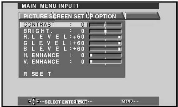
2 Press ▶ to select SCREEN.
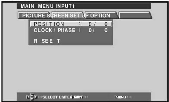
3 Press ▲/▼ to select the item to be adjusted.
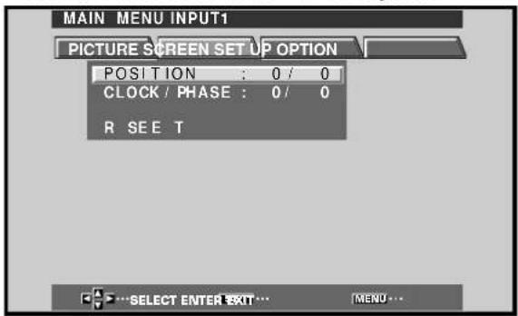
4 Press SET to display the adjustment screen for the selected item.
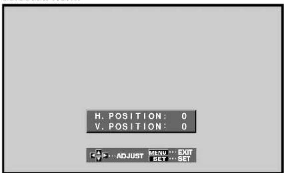
5 Press ▲/▼/◄/► to adjust the value.
Checking Supplied Accessories
Check that the following accessories were supplied.
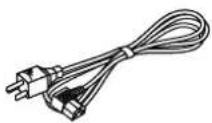
①Power cord
② Remote control unit
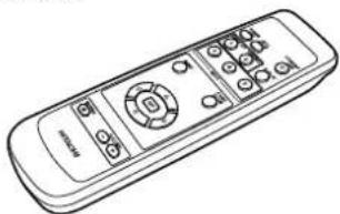
natural_image
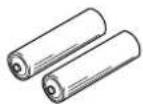
Line drawing of a remote control with buttons and dials (no text or symbols)③AA (R6) batteries (x 2)
④Speed clamps (x 2)
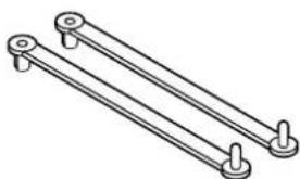
natural_image
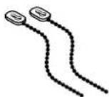
Technical line drawing of two parallel metal beams with mounting holes (no text or symbols)⑤Bead bands (x 2)
- USER'S MANUAL
Main Unit
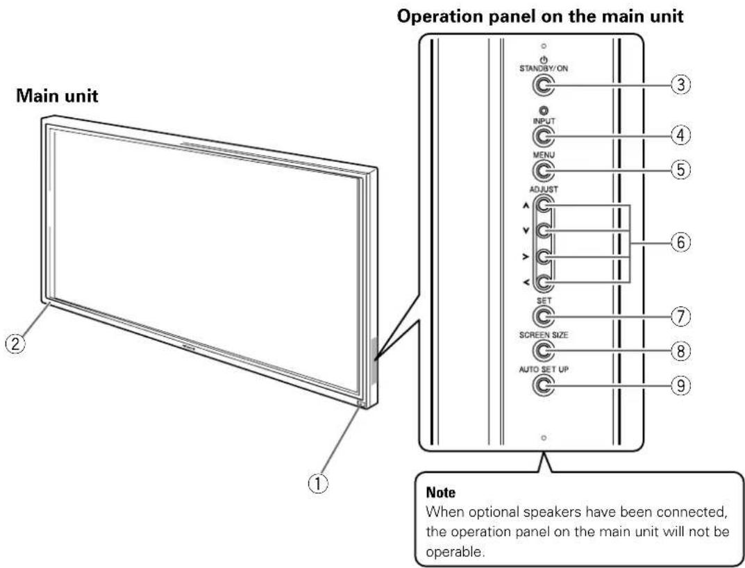
Main unit
① Remote control sensor
Point the remote control toward the remote sensor to operate the unit (page 6).
②STANDBY/ON indicator
This indicator is red during standby mode, and turns to green when the unit is in the operation mode (page 16).
Flashes green when Power-Management function is operating (page 20).
The flashing pattern is also used to indicate error messages (page 29).
Operation panel on the main unit
③STANDBY/ON button
Press to put the display in operation or standby mode (page 16).
④ INPUT button
Press to select input (page 16).
⑤MENU button
Press to open and close the on-screen menu (pages 14 to 26).
⑥ ADJUST (▲/▼/▶/◀) buttons
Use to navigate menu screens and to adjust various settings on the unit.
Usage of cursor buttons within operations is clearly indicated in the on-screen display (pages 14 to 26).
⑦SET button
Press to adjust or enter various settings on the unit (pages 14 to 26).
⑧SCREEN SIZE button
Press to select the screen size (page 18).
⑨ AUTO SET UP button
When using computer signal input, automatically sets the POSITION and CLOCK/PHASE to optimum values (page 22).
Remote Control Unit
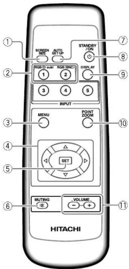
When handling the remote control unit
●Do not drop or shake the remote control.
- Do not use the remote control unit in a location subject to direct sunlight, heat radiation from a heater, or in a place subject to excessive humidity.
- When the remote control unit's batteries begin to wear out, the operable distance will gradually become shorter. When this occurs, replace all batteries with new ones as soon as possible.
① SCREEN SIZE button
Press to select the screen size (page 18).
②INPUT buttons
Use to select the input (page 16).
③MENU button
Press to open and close the on-screen menu (pages 14 to 26).
④ ADJUST (▲/▼/►/◄) buttons
Use to navigate menu screens and to adjust various settings on the unit.
Usage of cursor buttons within operations is clearly indicated at the bottom the on-screen menu display (pages 14 to 26).
⑤SET button
Press to adjust or enter various settings on the unit (pages 14 to 26).
⑥MUTING button
Press to mute the volume (page 17).
⑦ AUTO SET UP button
When using computer signal input, automatically sets the POSITION and CLOCK/ PHASE to optimum values (page 22).
⑧STANDBY/ON button
Press to put the unit in operation or standby mode (page 16).
⑨DISPLAY button
Press to view the unit's current input and setup mode (page 17).
⑩POINT ZOOM button
Use to select and enlarge one part of the screen (page 19).
⑪VOLUME (+/-) buttons
Use to adjust the volume (page 17).
Inserting the batteries in the remote control unit
While pressing down lightly, slide in the direction of the arrow.
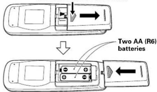
CAUTION
- Insert batteries so that the plus (+) and minus (−) sides are aligned according to the markings in the battery case.
●Do not mix new batteries with used ones.
●The voltage of batteries may differ even if they are the same shape. Please do not mix different kinds of batteries together. - When not using the remote control unit for a long period of time (1 month or more), remove the batteries from the remote control unit to prevent leaking of battery fluid. If battery liquid has leaked, thoroughly wipe the inside of the case until all liquid is removed, and then insert new batteries.
- Do not charge, short, disassemble or throw the provided batteries in a fire.
When disposing of used batteries, please comply with governmental regulations or environmental public instruction's rules that apply in your country or area. H048 En
Operating range of the remote control unit
When operating the remote control unit, point it at the remote sensor located on the front panel of the main unit. The remote control unit is operable up to 23 feet (7 m) from the unit and within a 30 angle on each side of the sensor.
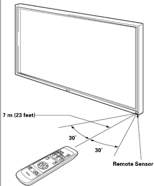
If you are having difficulty with operation of the remote control unit
●The remote control unit may not operate if there are objects placed between it and the display.
●Operational distance will gradually become shorter as the batteries begin to wear out, replace weak batteries with new ones as soon as possible.
- This unit discharges infrared rays from the screen. Placing a video deck or other component that is operated by an infrared remote control unit near this unit may hamper that component's reception of the remote control's signal, or prevent it from receiving the signal entirely. Should this occur, move the component to a position further away from this unit.
- Depending on the installation surroundings, this unit's remote control unit may be influenced by the infrared rays discharged from the plasma display, hampering reception of its rays or limiting its operational distance. The strength of infrared rays discharged from the screen will differ according to the picture displayed.
●This remote control unit has been designed to operate this display unit only, and it cannot be used to operate other devices.
Connection Panel
The connection panel is provided with two video input jacks and one video output jack. Audio input and speaker output jacks are also provided.
For instructions regarding connections, consult the pages noted in parentheses by each item.
①SPEAKER (R) terminal
For connection of an external right speaker. Connect a speaker whose impedance is 8 -16 Ω (page 12).
②CONTROL IN/OUT
DO NOT MAKE ANY CONNECTIONS TO THESE TERMINALS.
These terminals are used in the factory setup.
③COMBINATION IN/OUT
DO NOT MAKE ANY CONNECTIONS TO THESE TERMINALS.
These terminals are used in the factory setup.
④RS-232C
DO NOT MAKE ANY CONNECTIONS TO THIS TERMINAL.
This terminal is used in the factory setup.
⑤INPUT1 (mini D-sub 15 pin)
For connection of a personal computer (PC) or similar component. Make sure that the connection made corresponds to the format of the signal output from the connected component (pages 9 to 11).
⑥OUTPUT (INPUT1) (mini D-sub 15 pin)
Use the OUTPUT (INPUT1) terminal to output the video signal to an external monitor or other component.
Note: The video signal will not be output from the OUTPUT (INPUT1) terminal when the main power of this unit is off or in standby mode. (page 10)
⑦INPUT2 (BNC jacks)
For connection of a personal computer (PC) or similar component. Make sure that the connection made corresponds to the format of the signal output from the connected component (pages 9 to 11).
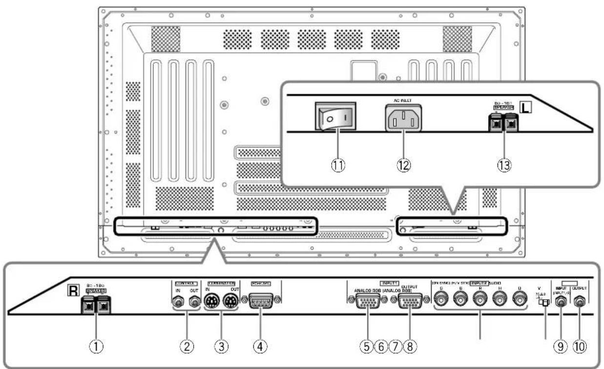
⑧ Synchronizing signal impedance selector switch
Depending on the connections made at INPUT2, it may be necessary to set this switch to match the output impedance of the connected component's synchronization signal.
When the output impedance of the component's synchronization signal is below 75 Ω, set this switch to the 75 Ω position (pages 9, 11).
Use to obtain sound when INPUT1 or INPUT2 is selected.
Connect the audio output jack of components connected to INPUT1 or INPUT2 to this unit (page 11).
Use to output the audio of the selected source component connected to this unit to an AV amplifier or similar component (page 11).
⑪ MAIN POWER switch
Use to switch the main power of the unit on and off.
⑫AC INLET
Use to connect the supplied power cord to an AC outlet (page 12).
⑬SPEAKER (L) terminal
For connection of an external left speaker. Connect a speaker that has an impedance of 8 -16 Ω (page 11).
Installation of the Unit
Installation using the optional HITACHI stand or installation bracket
- Please be sure to request installation or mounting of this unit or the installation bracket by an installation specialist or the dealer where purchased.
- When installing, be sure to use the bolts provided with the stand or installation bracket.
- For details concerning installation, please refer to the instruction manual provided with the stand or installation bracket.
Installation using accessories other than the HITACHI stand or installation bracket (sold separately)
- When possible, please install using parts and accessories manufactured by HITACHI. HITACHI will not be held responsible for accident or damage caused by the use of parts and accessories manufactured by other companies.
- For custom installation, please consult the dealer where the unit was purchased, or a qualified installer.
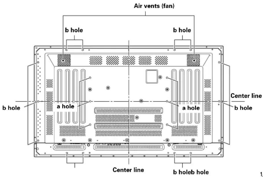
Rear view diagram
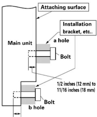
1/2 inch (12 mm) to 11/16 inch (18 mm)
Side view diagram
CAUTION
To avoid malfunction, overheating of this unit, and possible fire hazard, make sure that the vents on the main unit are not blocked when installing. Also, as hot air is expelled from the air vents, be careful of deterioration and dirt build up on rear surface wall, etc..
CAUTION
Please be sure to use an M8 (Pitch = 1.25 mm) bolt. (Only this size bolt can be used.)
AUTION
Because this unit weighs about 88 lbs 3 oz (about 40 kg) and the lack of depth makes it fairly unstable, please use 2 people or more when packing, carrying or installing.
AUTION
This unit incorporates a thin design. To ensure safety if vibrated or shaken, please be sure to take measures to prevent the unit from tipping over.
Connection to INPUT1 and INPUT2
The INPUT 1 and INPUT 2 jacks are used to connect the display to a computer. After making the connections, adjust the screen settings in accordance with the computer's signal output. See pages 14-15 for information regarding settings.
| Output source\INPUT2jack | [ON SYNC]G | B | R | [H/V SYNC]HD VD | |
| Personal computer (PC) with RGB output | OG ON SYNC | OB | OR | × | × |
| OG | OB | OR | OHV SYNC | × | |
| OG | OB | OR | HDD | OVD |
X: Do not connect anything. ⓄConnect to this jack.
Note
Components compatible with INPUT1 are also compatible with INPUT2.
INPUT1 is compatible with Microsoft's Plug & Play (VESA DDC 1/2B).
When making connections to INPUT1, please refer to supplement 2 on page 32.
For the screen sizes and input signals that INPUT1 and INPUT2 are compatible with, please refer to supplement 1 (page 31).
Connection to a personal computer \_\_\_\_
Connection method differs depending on the computer type. When connecting, please thoroughly read the computer's instruction manual.
Before making connections, be sure to make sure that the personal computer's power and this unit's main power is off.
For the PC input signals and screen sizes that this unit is compatible with, please refer to supplement 1 (page 31).
Connection of separate SYNC analog RGB source
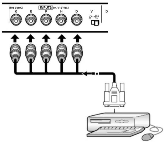
Make separate SYNC connections for a personal computer that has RGB output separated into 5 output signals: green, blue, red, horizontal synchronization signal, and vertical synchronization signal.
When connecting to INPUT2
flowchart
graph TD
    A["ON SYNC"] --> B["G"]
    C["INPUT2"] --> D["B"]
    E["H/V SYNC"] --> F["R"]
    G["H"] --> H["H"]
    I["D"] --> J["D"]
    K["V"] --> L["V"]
    M["75+3.8V"] --> N["Port"]
    O["75+3.8V"] --> P["Port"]
    Q["Port"] --> R["Computer"]
When using INPUT2, set the impedance selector switch to match the output impedance of the connected computer's synchronization signal.
When the output impedance of the computer's synchronization signal is below 75 Ω, set this switch to the 75 Ω position.
On-screen setup is necessary after connection.
Please see pages 14 and 15.
When connecting to INPUT1
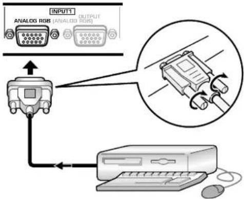
Connect the cable corresponding to the shape of the input terminal on this unit and the personal computer's output terminal.
Secure by tightening the terminal screws on both units.
After connecting, on-screen setup is necessary.
Please see pages 14 and 15.
Note
Depending on the type of computer model being connected, a conversion connector or adapter etc. provided with the computer or sold separately may be necessary.
For details, please read your PC's instruction manual or consult the maker or nearest dealer of your computer.
When connecting to OUTPUT (INPUT1)
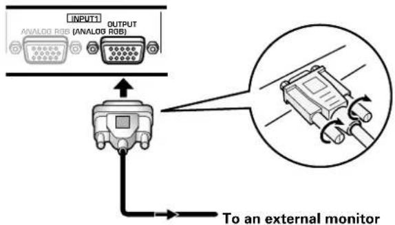
With this unit, it is possible to output the video signal to an external monitor or other component from the OUTPUT (INPUT1) terminal.
Note
A video signal will not be output from the OUTPUT (INPUT1) terminal when the main power of this unit is off or in standby.
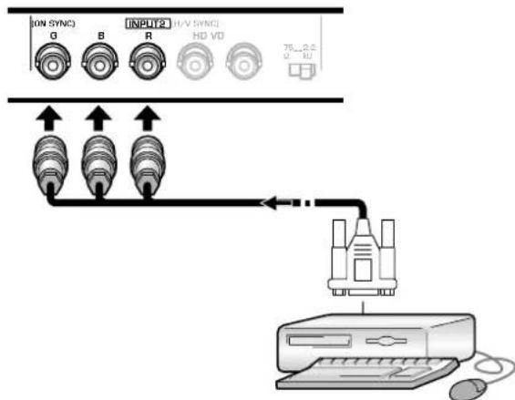
Connection of G ON SYNC analog RGB source
Make G ON SYNC connections for a personal computer with output that has the synchronization signal layered on top of the green signal.
When connecting to INPUT1
![INPUT1 ANALOG RGB [ANALOG RGB] OUTPUT](/content/2026/05/1050847/images/88beeb9e449f0d3f5c8316d552d2172e50fef75b71f4615011bc2ea7e171be71.jpg)
On screen setup is necessary after connection.
Please see pages 14 and 15.
When connecting to INPUT2
flowchart
graph TD
    A["ON SYNC"] --> B["INPUT2"]
    B --> C["HD VD"]
    C --> D["75...2.2"]
    D --> E["Computer"]
    F["Device"] --> G["Computer"]
    style A fill:#f9f,stroke:#333
    style B fill:#ccf,stroke:#333
    style C fill:#cfc,stroke:#333
    style D fill:#fcc,stroke:#333
    style E fill:#cff,stroke:#333
On screen setup is necessary after connection.
Please see pages 14 and 15.
Note
When making G ON SYNC connections, do not make any connections to the VD or HD jacks. If connections are made, the picture may be not displayed normally.
Connection of composite SYNC analog RGB source
Make composite SYNC connections for a personal computer with output that has the vertical synchronization signal layered on top of the horizontal synchronization signal.
When connecting to INPUT1
![INPUT:1 ANALOG RGB [ANALOG RGB] OUTPUT ← Computer ←](/content/2026/05/1050847/images/c32acc1635a135bac24997e99080fead3c9704ea887a8002edf619da20c92b93.jpg)
On-screen setup is necessary after connection. Please see pages 14 and 15.
When connecting to INPUT2
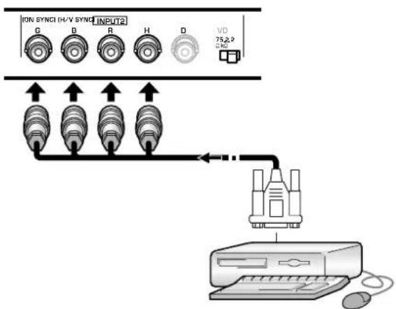
flowchart
graph TD
    A["ION SYNCI (H/V SYNCI INPUT2)"] --> B["G"]
    A --> C["B"]
    A --> D["R"]
    A --> E["H"]
    A --> F["D"]
    A --> G["VD 75.8.9 0 kΩ"]
    B --> H["↑"]
    C --> I["↑"]
    D --> J["↑"]
    E --> K["↑"]
    F --> L["↓"]
    G --> M["←"]
    M --> N["Computer"]
When using INPUT2, set the impedance selector switch to match the output impedance of the connected computer's synchronization signal.
When the output impedance of the computer's synchronization signal is below 75 Ω, set this switch to the 75 Ω position.
On-screen setup is necessary after connection. Please see pages 14 and 15.
Notes
- When making composite SYNC connections, do not connect anything to the VD jack. If connected, the picture may not be displayed properly.
- On some types of Macintosh ^ components, G ON SYNC and composite SYNC are both output. With this type of component, please connect using the G ON SYNC connection (see page 10).
Audio Connections
Before making connections, be sure to check that the audio component's power and the unit's main power is off.
Connecting the speakers
This unit is equipped with speaker output jacks for connection to the speaker system (not supplied) specially designed for use with this unit. Refer to the illustrations below when making connections to the speaker terminals on this unit.
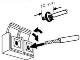
Twist exposed
wire strands
together.
Push tab to the open position, and insert the wire. Then, close tab firmly to secure the wire in place.
Note
When making speaker connections, be sure to match the polarities (+ and -) of the speaker terminals on this unit and the corresponding terminals on the speakers. If the polarity is reversed, the sound will be unnatural and lack bass.
Making connections to the audio inputs on this unit
This unit features two audio inputs and one audio output. The following chart shows the video inputs and the corresponding audio input jacks.
| Video input | Audio input jacks | Sound output |
| INPUT1 | Stereo mini jack (L/R) | Sound of the selected video input is output from theSPEAKER terminalsStereo mini jacks (L/R). |
| INPUT2 |
Audio connections for component (computer) connected to INPUT 1 or INPUT 2
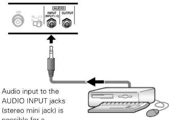
component connected to either INPUT1 or INPUT2. Sound is output from both the AUDIO OUTPUT jacks (stereo mini jack) and the SPEAKER terminals according to the video input selection.
Power Cord Connection
Connect the power cord after all component connections have been completed.
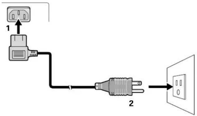
1 Connect the power cord to this unit.
2 Plug the power cord into a power outlet.

CAUTION
- Use only the power cord provided.
- Do not use a power supply voltage other than that indicated (AC 100 - 120 V, 50/60 Hz) as this may cause fire or electric shock.
- For the plasma display, a three-core power cord with a ground terminal is used for efficiency protection. Always be sure to connect the power cord to a three-pronged grounded outlet and make sure that the cord is properly grounded. If you use a power source converter plug, use an outlet with a ground terminal and screw down the ground line.
How to Route Cables
Speed clamps and bead bands are included with this unit for bunching cables together. Once components are connected, follow the following steps to route cables.
* As viewed from the rear of the display.
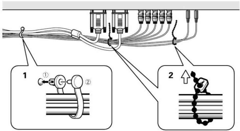
1 Organize cables together using the provided speed clamps.
Insert ① into an appropriate hole on the rear of the unit, then snap ② into the back of ① to fix the clamp.
Speed clamps are designed to be difficult to undo once in place. Please attach carefully.
2 Bunch separated cables together and secure them with the provided bead bands.
Note
Cables can be routed to the right or left.
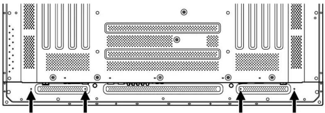
To attach the speed clamps to the main unit
Connect the speed clamps using the 4 holes marked with • below, depending on the situation.
natural_image
Back panel diagram of a server rack with multiple Ethernet ports and ventilation slots (no text or labels)To remove speed clamps
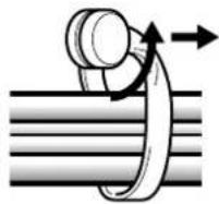
Using pliers, twist the clamp 90^ and pull it outward. In some cases the clamp may have deteriorated over time and may be damaged when removed.
Setup after Connection
After components have been connected to INPUT1 or INPUT2, on-screen setup is necessary.
Follow the procedure described below and make settings as they apply to the type of components connected.
Screen Mode setup
Note
These settings are required only when using the following input signal refresh rates: ① 31.5 kHz horizontal / 60 Hz vertical; ② 48.4 kHz horizontal / 60 Hz vertical, or 56.5 kHz horizontal / 70 Hz vertical. No manual setup is necessary for signals with other refresh rates, since adjustments are performed automatically (the SETTING item will not be displayed).
1 Switch MAIN POWER on the connection panel to the on position to turn on the unit's main power.
The STANDBY/ON indicator lights red.
2 Press STANDBY/ON to put the unit in the operation mode.
The STANDBY/ON indicator turns green.
3 Select INPUT1 or INPUT2.
4 Press MENU to display the menu screen.
The menu screen appears.
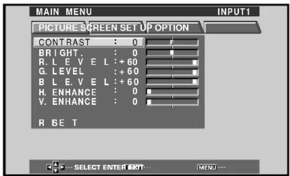
5 Press ◀/▶ to select SET UP.
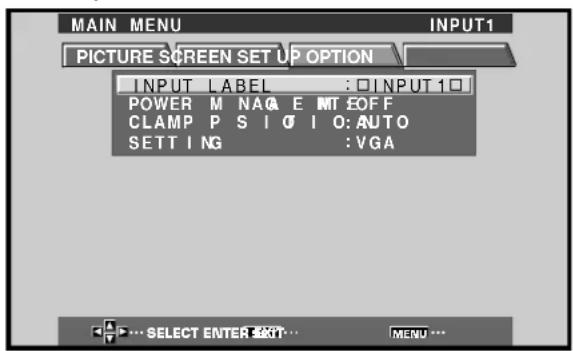
6 Press ▲/▼ to select SETTING, then press SET.
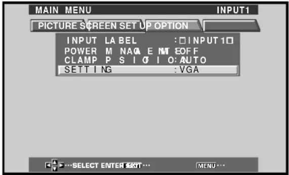
7 Press ◀/▶ to select the display mode.
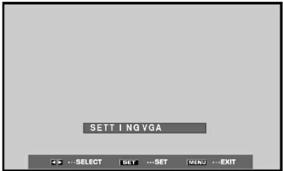
① When the input signal has a refresh rate of 31.5 kHz (horizontal) and 60 Hz (vertical), pressing ◀/▶ will cause the display mode to change alternately as follows:

② When the input signal has a refresh rate of 48.4 kHz horizontal / 60 Hz vertical, or 56.5 kHz horizontal / 70 Hz vertical, pressing ◀/▶ will cause the display mode to change alternately as follows:

8 When the setup is completed, press MENU to exit the menu screen.
Note
Make this setup for each input (INPUT1 and INPUT2).
CLAMP POSITION setup
Depending on the signal, analog RGB signals may result in the screen image appearing with a whitish or greenish cast. In such cases, set "CLAMP POSITION" to LOCKED.
●Normally, leave this setting at AUTO.
Setup of CLAMP POSITION
1 Press MENU to display the menu screen.
The menu screen appears.
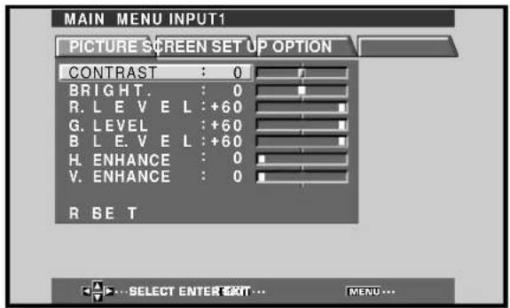
2 Press ◀/▶ to select SET UP.
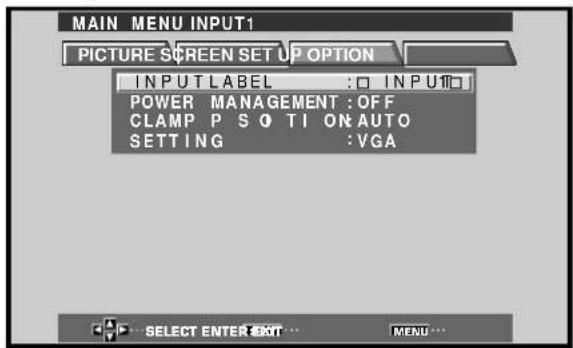
3 Press ▲/▼ to select CLAMP POSITION.
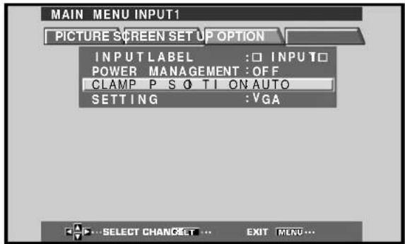
4 Press SET to select LOCKED.
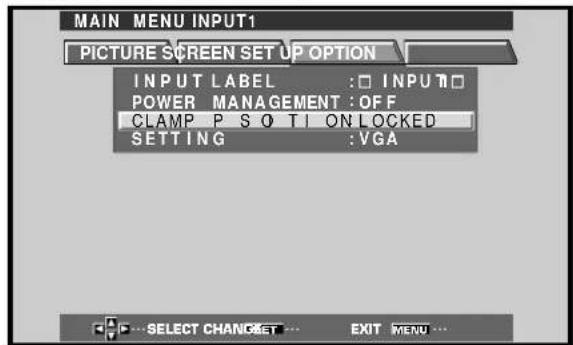
Mode selection will change as follows each time SET is pressed.

5 When the setup is completed, press MENU to exit the menu screen.
Notes
- Make this CLAMP POSITION setting for each applicable input (INPUT1 and INPUT2).
- When using this setup, be sure to carefully check the signal output of the component that you are using. For details, please refer to the instruction manual supplied with the component you are connecting.
Selecting an Input Source
This section explains the basic operation of this unit. Outlined on the following pages is how to turn the main power on and off, put this unit in the operation or standby mode and how to select connected components.
Before you begin, make sure you have:
- Made connections between this unit and personal computer as described in the section "Installation and Connections" starting on page 8.
- Set up the on-screen menu to input signals from components connected to INPUT1 and INPUT2 as described in the section "Setting Up the System" on page 14.
If no connections are made to these terminals, on-screen setup is not necessary.
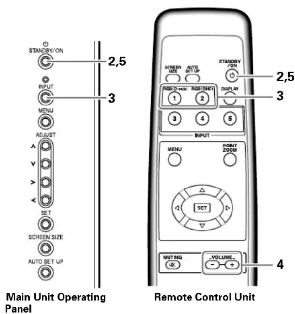
1 Switch MAIN POWER on the main unit to the on position to turn the main power on.
The STANDBY/ON indicator lights red.
2 Press STANDBY/ON to put this unit in the operation mode.
The STANDBY/ON indicator turns green.
3 Press INPUT on the remote control unit or the main unit to select the input.
Input changes each time the main unit's INPUT is pressed as follows.
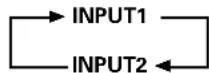
- When the menu screen is displayed, changing the signal input will cause the menu screen to turn off.
- If the input computer signal is not supported by the display, the following message will be displayed:
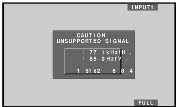
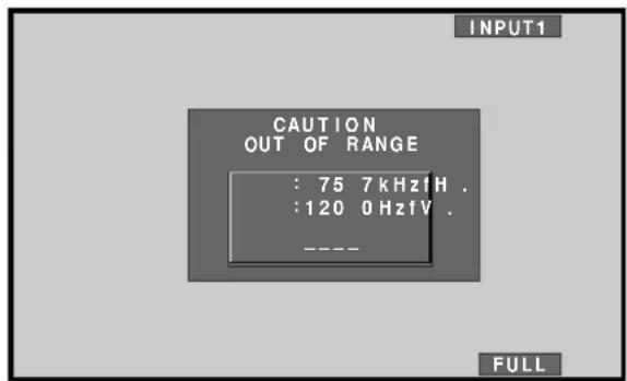
4 Use VOLUME +/- on the remote control unit to adjust the volume.
If no audio connections are made to this unit, this step is not necessary.
5 When viewing is finished, press STANDBY/ON to put the unit in standby mode.
The STANDBY/ON indicator will blink and then remain lit (red) indicating that the standby mode is engaged. Operation is not possible while the STANDBY/ON indicator is blinking (red).
6 Switch MAIN POWER on the main unit to the off position to turn the main power off.
The STANDBY/ON indicator may continue to light for a short while even after the main power is turned off. This is a result of residual electric load impressed on the circuitry, and the light will turn off presently.
CAUTION
Please do not leave the same picture displayed on the screen for a long time. Doing so may cause a phenomenon known as "screen burn" which leaves a ghost, or residual, image of the picture on the screen.
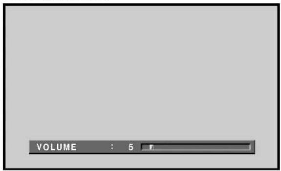
To adjust the volume
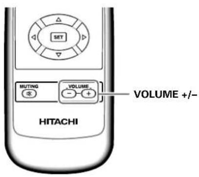
Press VOLUME on the remote control unit.
Use VOLUME + or VOLUME – to adjust the volume of the connected speakers.
To mute the sound
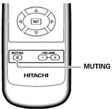
Press MUTING on the remote control unit.
Press MUTING again to restore the sound.
Muting is automatically canceled about 8 minutes after the button is pressed, and the volume level is adjusted to the minimum level.
Press VOLUME + or VOLUME - to adjust the volume at a desired level.
To confirm display settings
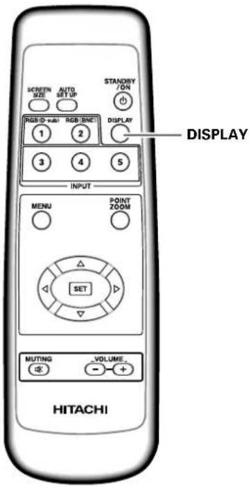
Press DISPLAY on the remote control unit.
The currently selected input, screen size and refresh rates will be displayed for about 3 seconds.
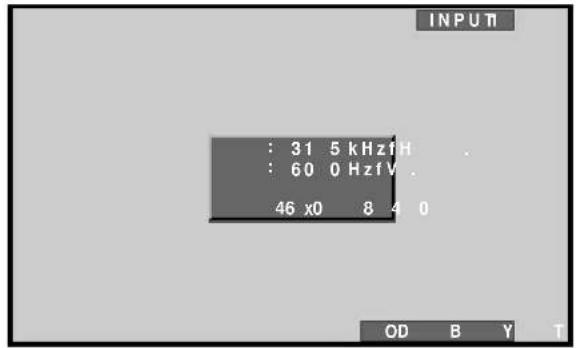
Note
The displayed refresh rates may be slightly different from actual values.
Screen Size Selection
This unit incorporates screen modes of various height and width ratios. For optimal viewing, we recommend that you select the screen mode that best matches the video source that you are viewing. Although these modes are designed for full display of a picture on a wide screen, it is our hope that you make use of them with a full understanding of the manufacturer's intentions.
Changing the screen size
The size of the picture or the picture's range projected on the screen can be changed between 4 screen sizes described in the table on this page.
Press SCREEN SIZE to select the size.
The screen size changes each time SCREEN SIZE is pressed as follows.

Consult the table Computer Signal Formats Supported (page 31) for information regarding screen sizes supported by each signal format.
Notes
- When the PARTIAL or FULL setting is used to display a non-wide screen 4:3 picture fully on a wide screen, a portion of the picture may be cut off or appear deformed.
- Be aware that when the display is used for commercial or public viewing purposes, selecting the PARTIAL or FULL mode settings may violate the rights of authors protected under copyright law.
- When DOT BY DOT or 4:3 screen sizes are selected, the display position is moved slightly each time the power is turned on, in order to prevent image burning.
Moving the screen position upward or downward
During personal computer input (1280 x 1024/60Hz only), even when the PARTIAL setting is selected, the position of the screen can be adjusted by using ▲/▼. The adjustment value will not, however, be stored in memory.
During personal computer signal input
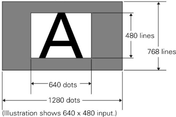
① DOT BY DOT
The input signal and the screen maintain a dot to line ratio of 1:1 and is thus highly faithful to the source.
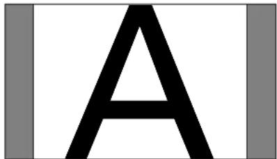
② 4:3
The display fills the screen as much as possible without altering the aspect ratio of the input signal.
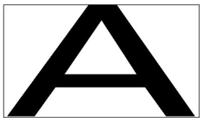
③ FULL
The display is presented with a widescreen aspect ratio of 16:9 and fills the entire screen.
④ PARTIAL
The PARTIAL setting is available only during personal computer input (1280 x 1024/60 Hz only).
The input signal and the screen maintain a dot to line ratio of 1:1. Display is highly faithful to the source. However, in order to maintain the 1:1 ratio, a portion of the display will not appear on the screen.
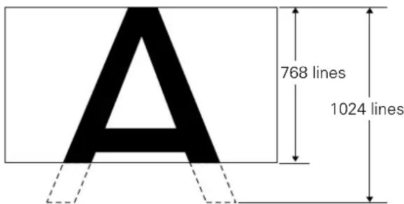
Use ▲/▼ to adjust the position of the video image on the screen.
Partial Image Enlargement (POINT ZOOM)
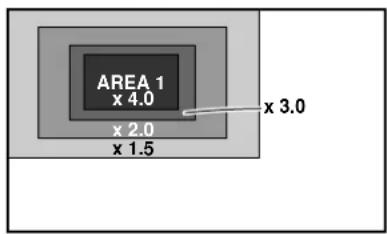
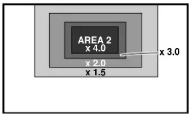
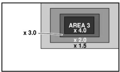
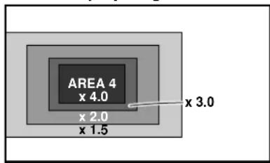
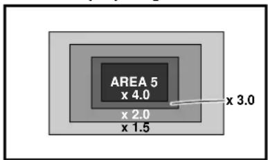
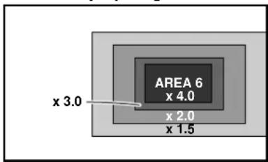
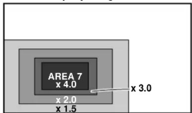
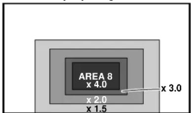
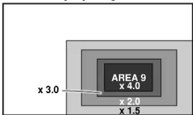
This display allows any one of nine screen areas (AREA 1 to AREA 9) to be selected and enlarged to x1.5, x2, x3, or x4. When performing point zoom enlargement, the direction buttons (▲/▼/◄/►) can be used to move the enlarged portion up-down and right-left.
1 Press the remote control unit's POINT ZOOM.
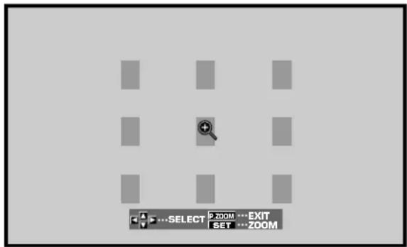
2 Press ▲/▼/◄/► as required to select the desired screen area (AREA 1 to AREA 9).
3 Press SET to select the zoom ratio.
Pressing SET repeatedly changes the zoom ratio in the following order:
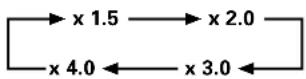
- When the zoom ratio is changed, the screen image is enlarged based on the screen center.
- ▲/▼/◄/► can be used to move the enlarged portion up-down and right-left.
- If no operation is undertaken for three seconds or more, the display screen will disappear. SET or ▲/▼/◄/► can be pressed again if desired to change the zoom ratio or display position.
4 Press the remote control unit's POINT ZOOM once again to cancel the point zoom operation.
The point zoom function will also be canceled whenever the input signal changes, the menu screen is displayed, or the INPUT changes.
Note
Whenever point zoom is selected, the screen size automatically changes to FULL.
AREA 1 display range
AREA 2 display range
AREA 3 display range
AREA 4 display range
AREA 5 display range
AREA 6 display range
AREA 7 display range
AREA 8 display range
AREA 9 display range
Automatic Power OFF
This display is equipped with automatic power-management and auto-power-off functions, which allow the unit to automatically switch to power-saving mode when no sync signal is detected.
(A warning message appears onscreen before these functions operate.)
Notes
●The Power Management function can be set only when the INPUT 1 signal is selected.
●The automatic power-off function can be set only when the INPUT 2 signal is selected.
- Always turn off the plasma display's main power switch when not using the display for extended periods of time.
1 Press MENU to display the menu screen.
2 Press ◀/▶ to select SET UP. [When using INPUT 1]
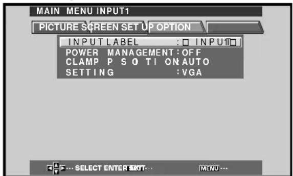
[When using INPUT 2]
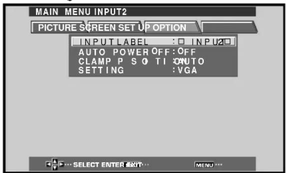
3 Press ▲/▼ to select either the POWER MANAGEMENT or AUTO POWER OFF mode. [When using INPUT 1]
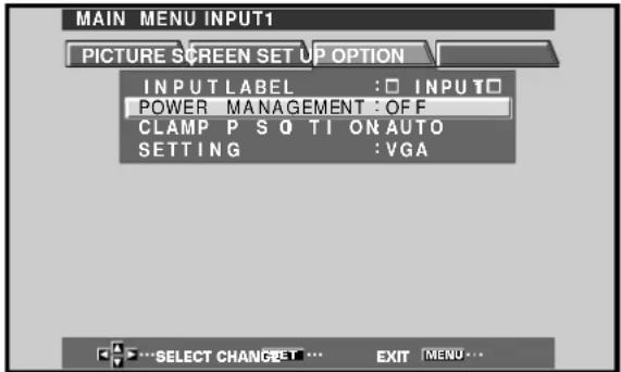
[When using INPUT 2]
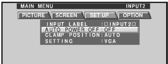
4 Press SET to confirm selection of the POWER MANAGEMENT or AUTO POWER OFF.
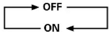
- When OFF is selected, the display will continue in operating mode, regardless of the presence/absence of an input sync signal.
- When POWER MANAGEMENT: ON is selected, if a sync signal is not detected, a warning message is displayed for 8 seconds, after which the display automatically enters the power-saving mode (*1) and the STANDBY/ON indicator flashes green. If a sync signal (*2) is input again later, the plasma display automatically returns to normal operating mode.
*1. Power consumption about 1W
*2. Except when input signal is G on SYNC or composite SYNC - When AUTO POWER OFF: ON is selected, if no sync signal is detected for 8 minutes or more, a warning message will be displayed for 30 seconds, after which the unit's power will switch to STANDBY mode.
5 When the setup is finished, press MENU to exit the menu screen.
Note
The POWER MANAGEMENT and AUTO POWER OFF functions must be set individually for each input (INPUT 1 or INPUT 2).
To return to operating mode:
● To return to normal operation from POWER
MANAGEMENT mode: either operate the computer, or press INPUT on the display or remote control unit.
- To return to normal operation from AUTO POWER OFF mode: Press STANDBY/ON on the display or remote control unit.
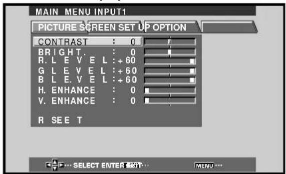
Adjusting the Picture Quality
1 Press MENU to display the menu screen.
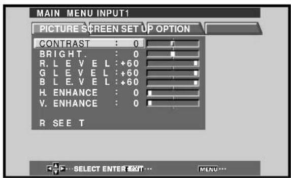
2 Press ▲/▼ to select the adjustment item, then press SET.
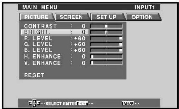
3 Press ◀/▶ to adjust the picture quality as desired.
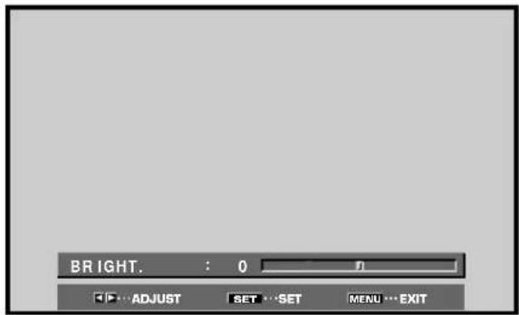
4 Press SET.
Pressing SET writes the value into the memory and returns the display to the step 2 screen.
5 When the setup is finished, press MENU to exit the menu screen.
Note
Make these adjustments for each input (INPUT1 to INPUT2) and signals.
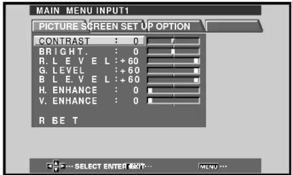
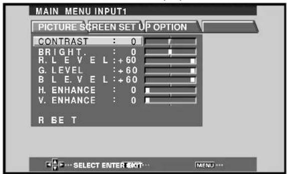
PICTURE mode adjustment items
Below are brief descriptions of the options that can be set in the PICTURE mode.
CONTRAST ....Adjust according to the surrounding brightness so that the picture can be seen clearly.
BRIGHT. ....Adjust so that the dark parts of the picture can be seen clearly.
R. LEVEL .... Adjust the amount of red in the picture.
G. LEVEL .... Adjust the amount of green in the picture.
B. LEVEL ....Adjust the amount of blue in the picture.
H. ENHANCE…… Sharpens the image in the horizontal direction.
V. ENHANCE …… Sharpens the image in the vertical direction.
To reset PICTURE mode settings to the default
If settings have been adjusted excessively or the picture on the screen no longer appears natural, it may prove more beneficial to reset the PICTURE mode to default settings instead of trying to make adjustments under already adjusted conditions.
1 In step 2 in the previous procedure, press ▲/▼ to select RESET, then press SET.
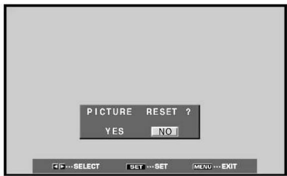
2 Press ◀/▶ to select YES, and press SET.
All PICTURE mode settings are returned to the factory set default.
Adjusting the Image Position and Clock (Automatic Adjustment)
Pressing AUTO SET UP on either the main unit or the remote control unit will adjust the screen position and clock to optimum values.
Note
Perform this adjustment individually for each input function (INPUT 1, INPUT 2), and each signal type.
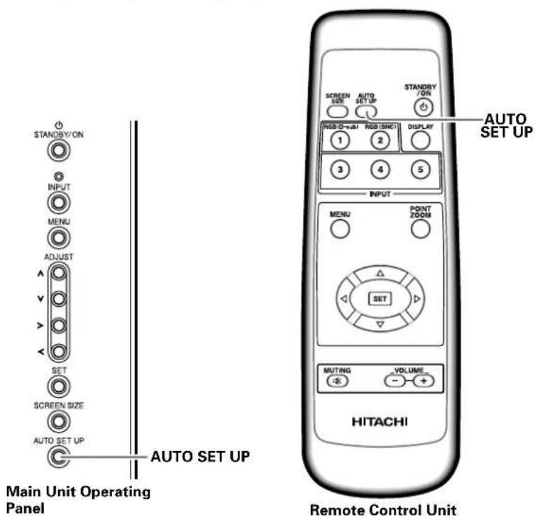
Press AUTO SET UP on either the main unit or remote control unit.
- Optimum settings may not be possible for low-luminance and certain other kinds of signals. In this case, following the instructions in the following section "Manual Adjustment of Screen Position and Clock" to make more precise adjustments.
Manual Adjustment of Screen Position and Clock
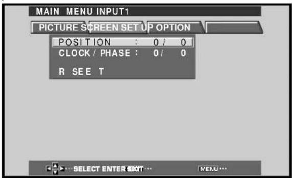
1 Press MENU to display the menu screen.
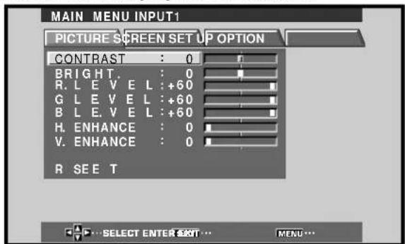
2 Press ◀/▶ to select SCREEN.
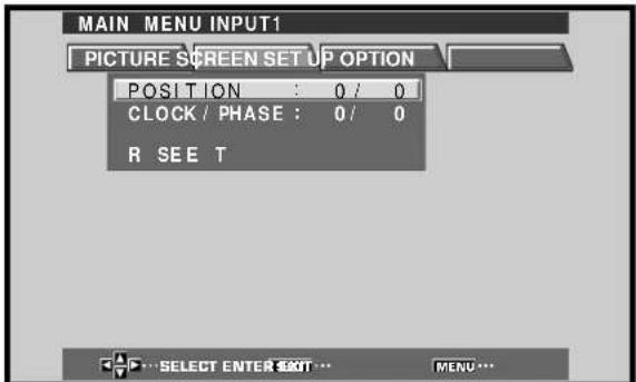
3 Press ▲/▼ to select the adjustment item, then press SET.
4 Press ◀/▶ to carry out the adjustment.
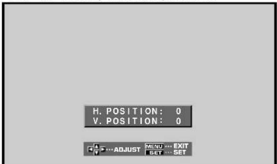
Use ▲/▼ for the adjustments of V.POSITION and PHASE.
5 Press SET.
Pressing SET writes the value into the memory and returns the display to the step 3 screen.
6 When adjustment is finished, press MENU to exit the menu screen.
Note
Make these adjustments for each input (INPUT1 to INPUT2) and signals.
SCREEN mode adjustment items
Below are brief descriptions of the options that can be set in the SCREEN mode.
POSITION
H. POSITION…… Adjust the picture's position to the left or right.
V. POSITION …… Adjust the picture's position upward or downward.
CLOCK/PHASE
CLOCK. ....Adjust letter breakup or noise on the screen. This setting adjusts the unit's internal clock signal frequency that corresponds to the input video signal.
PHASE ....Adjust so that there is minimum flicker of screen letters or color misalignment. This setting adjusts the phase of the internal clock signal adjusted by the CLOCK setting.
Notes
- When CLOCK adjustment is carried out, the H.POSITION setting may have to be re-adjusted.
- If the adjustment items in the SCREEN mode are adjusted excessively, the picture may not be displayed properly.
To reset SCREEN mode settings to the default
If settings have been adjusted excessively or the picture on the screen no longer appears natural, it may prove more beneficial to reset the SCREEN mode to default settings instead of trying to make adjustments under already adjusted conditions.
1 In step 3 in the previous procedure, press ▲/▼ to select RESET, then press SET.
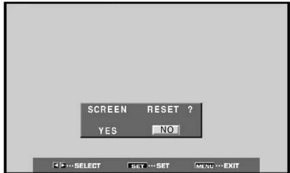
2 Press ◀/▶ to select YES, and press SET.
All SCREEN mode settings are returned to the factory set default.
Rewriting the Input Display (INPUT LABEL)
This function allows rewriting of the screen contents displayed with differing inputs. For example, the default "INPUT 1" can be changed to "COMPUTER" or other name describing the connected component (up to maximum of 8 characters).
Example: To rewrite the default "INPUT 1" message to display "COMPUTER" instead.
1 Press INPUT and set input to INPUT 1.
2 Press MENU to display the menu screen.
3 Press ◀/▶ to select SET UP.
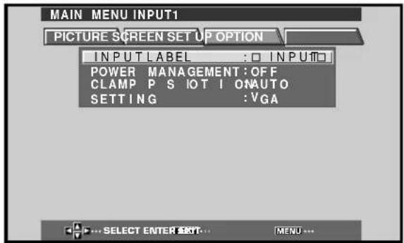
4 Press SET to select INPUT LABEL.
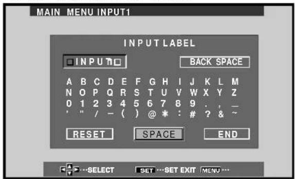
5 Press ▶/▶/▲/▼ to select the first desired character (here, "C"), then press SET to confirm (repeat this step to input up to eight desired characters.)
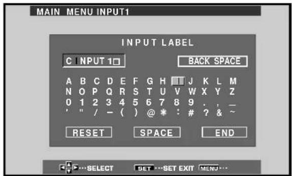
- Usable characters include 52 types displayable on screen.
- When a character is selected and SET pressed, the input point (cursor position) advances by one.
- If you input a mistaken character, press BACK SPACE followed by SET to move the input point (cursor position) back by one.
- To return the display to its default value, press RESET followed by SET.
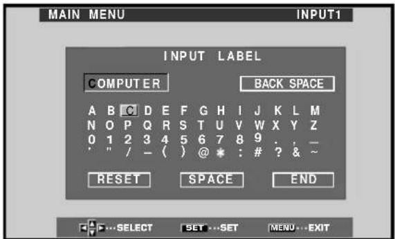
6 After setting all inputs as desired, press ◀/▶/▲/▼ to select END, followed by SET.
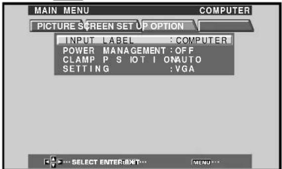
7 Press MENU to return to the normal display screen.
Power Control Function
The power control function allows screen brightness to be suppressed as a means of lowering power consumption and reducing display deterioration.
1 Press MENU to display the menu screen.
The menu will be displayed.
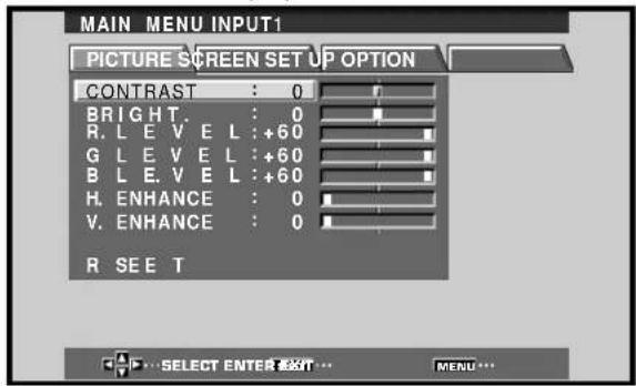
2 Press ◀/▶ to select OPTION.
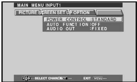
3 Press SET to select POWER CONTROL.
The unit has been factory set to the STANDARD setting. Each time SET is pressed, the setting changes as follows:

- When STANDARD is set, screen brightness is reduced in accordance with the input signal, thus producing bright, easy-to-view images.
- Selecting MODE 1 reduces brightness in the same way as the STANDARD setting, but at a even lower levels of power consumption.
- MODE 2 fixes the screen brightness regardless of the input signal. This is effective at reducing panel deterioration due to screen burning.
4 Following completion of settings, press MENU to return to normal screen display.
Note
The POWER CONTROL setting affects all input sources.
AUTO FUNCTION
This display is equipped with an optional AUTO FUNCTION selector. When enabled, the selector automatically switches the display's input source to INPUT 1 when an image signal is detected at the INPUT 1 jack.
1 Press MENU;
The onscreen menu will be displayed.
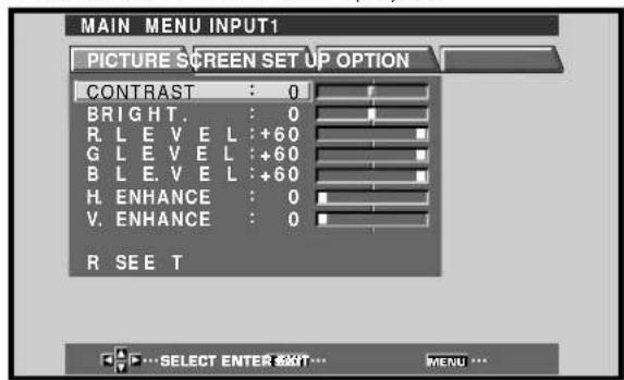
2 Press ◀/▶ to select OPTION.
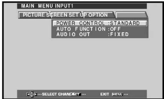
3 Press ▲/▼ to select AUTO FUNCTION.
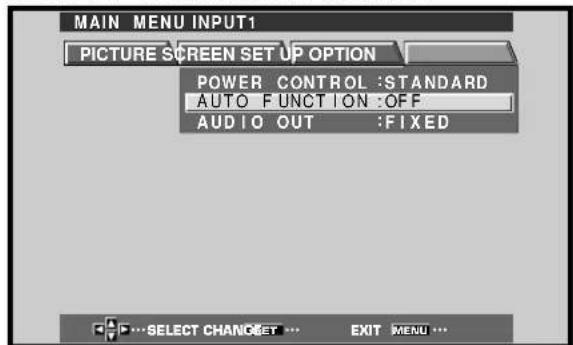
4 Press SET to select INPUT 1.
The factory default setting is OFF. Each time SET is pressed the selector function switches alternately as shown:
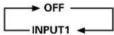
- When OFF is selected, AUTO FUNCTION is disabled.
- When INPUT 1 is selected, the display input automatically switches to INPUT 1 when a signal is detected at the INPUT 1 jack. Thereafter, the input will not change even if the INPUT button is pressed on the remote control unit or display. Once the function has switched to INPUT 1 by operation of the AUTO FUNCTION facility, if the input signal is no longer detected at the INPUT 1 jack, the function will automatically switch back to the original input source used before the AUTO FUNCTION facility was enabled.
5 Following completion of settings, press MENU again to return the display to its normal screen.
Note
The AUTO FUNCTION for INPUT1 is supported only when a separate SYNC or composite SYNC analog RGB signal is input. (When a G on SYNC or component video signal is input, AUTO FUNCTION is disabled.)
Audio Output (AUDIO OUT)
The signal level produced at the AUDIO OUT jack can be set to FIXED or VARIABLE (linked to the VOLUME) as desired.
1 Press MENU;
The onscreen menu will be displayed.
2 Press ◀/▶ to select OPTION.
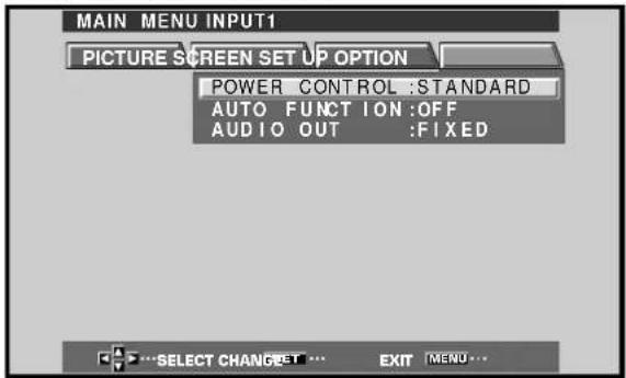
3 Press ▲/▼ to select AUDIO OUT.
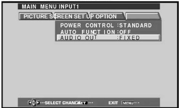
4 Press SET to select the desired audio level setting.
The factory default setting is FIXED. Each time SET is pressed, the function alternates as shown:
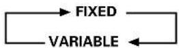
- When FIXED is selected, the audio output volume will not change, even if the setting of the display's VOLUME function is later changed.
- When VARIABLE is selected, the level of the output signal changes in accordance with the setting of the VOLUME function.
5 Following completion of settings, press MENU to return to normal screen display.
Note
The AUDIO OUT setting affects all input sources.
Cleaning
Regular cleaning will extend the life and performance of this unit. The recommended way to clean the display and related parts is described below.
Before cleaning, be sure to unplug the power cord from the power outlet.
Cleaning the display panel body and remote control
Do not under any circumstances use solvents such as benzine or thinner for cleaner. Use of such liquids may cause deterioration or peeling of paint from the display or remote control unit.
Wipe the display and remote control gently with a soft cloth. In the case of excessive dirt buildup, dampen a soft cloth with a diluted neutral cleaning detergent and after wringing the cloth thoroughly, wipe the component and then dry it with a dry soft cloth.
Cleaning the screen
After dusting, wipe the screen gently using a soft cloth. Do not use tissue or a rough cloth. As the surface of the screen is easily scratched, do not rub it or hit it with a hard object.
Cleaning the vents
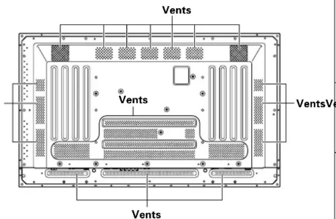
As a general rule, use a vacuum cleaner about once a month to clean the vents on the rear panel of the display of dust buildup (set the vacuum cleaner to its weakest setting when doing this).
Using the unit without cleaning it of dust will cause the internal temperature to increase, resulting in possible breakdown or fire.
Troubleshooting
What may at first seem to be an malfunction, may be remedied with a quick check.
Please check to see if a warning is displayed on the screen. If displayed, refer to the table below and check the mode. If there is no display check to see if the problem is listed on page 28. The problem may also be caused by something other than this unit so please also check the other components being used such as a video deck. If the problem can still not be solved please consult the dealer where this unit was purchased.
About the self diagnosis mode
Messages appear on the bottom of this unit's screen to indicate operation or connection faults. After message confirmation, check the condition of the unit.
| ERROR MESSAGE | REMEDY |
| CAUTIONOUT OF RANGE orCAUTIONUNSUPPORTED SIGNAL | ●The current input signal is not supported by the unit. Consult the table of supported computer input signals on page 31 and set the computer's output signal appropriately. |
| WARNING THERMAL ALERT | ●Turn off main power (page 7).●Is ambient temperature too high?●Remove any objects blocking the cooling vents on the plasma display. |
| WARNING FAN FAILURE | ●Cooling fan has malfunctioned. Immediately turn off power, remove power plug from its outlet, and consult a Pioneer service center or your dealer. |
| ERROR INVALID KEY ENTRYents | ●An invalid operation has been attempted. Check input signals, connections and other settings. |
| SHUT DOWN | ●Turn off main power, wait for 1-2 minutes, then try turning power on again. If problem persists, remove power plug from its outlet and consult a Pioneer service center or your dealer. |
General problems
| Problem Possible Solution | |
| No power | Is the power cord disconnected? (page 12)Has the MAIN POWER switch been switched on? (page 7) |
| Unit cannot be operated. | External influences such as lightning, static electricity, etc., may cause improper operation. In this case, operate the unit after first turning the MAIN POWER on/off, or unplugging the power cord and re-plugging it in after 1 to 2 minutes. |
| Remote control does not operate. | Are batteries inserted with polarity (+,-) correctly aligned? (page 5)Are batteries worn out? (Replace with new batteries). |
| INPUT is not changed. | Is the Auto function being used? (pages 25–26) |
| Picture is cut off. | Is the selected screen size correct?Switch to another screen size (page 18).Are SCREEN mode adjustments such as picture size made correctly? (pages 22–23)Is the Point Zoom function being used? (page 19) |
| Strange color, light color, or dark, or color misalignment | Adjust the picture tone (page 21).Is the room too bright?The picture may look dark in a room that is too bright. |
| Power is suddenly turned off. | The unit's internal temperature has increased. (Air vents are blocked.)Remove any objects blocking vent or clean (page 27).Is the POWER MANAGEMENT or AUTO POWER OFF function set to ON? (page 20).Condensation has formed on internal parts due to suddenly increasing ambient temperature.Allow condensation to dry thoroughly before using. |
| No picture | Is connection to other components correct? (pages 9 to 11)Has setup been done correctly after connection? (pages 14 and 15)Is the correct input selected? (page 16)Is a non-compatible signal being input? (pages 9 and 31)Is picture adjustment correct? (page 21) |
Problems commonly mistaken as breakdown
| Problem Possible Solution | |
| The screen is displayed in a small size. | Check the input signal compatibility chart (page 31).Is the correct screen size selected? (pages 18, 22 and 23) |
| Letter breakup on screen. | Adjust using "SCREEN" mode on the menu screen (page 23).If there is still no improvement, this unit may be limiting the displayable range. Check the personal computer input signal compatibility chart (page 31). |
| A sharp sound is sometimes heard from the cabinet. | Expansion/contraction caused by surrounding temperature change may result in sound being heard from the cabinet. This is not a malfunction. |
| Bright portions of image appear to be losing intensity. | When the video input signal's level is too high, the bright portions may appear to be losing their intensity.Increase the adjustment level of the contrast and check the picture (page 21). |
| Speckles or noise appears on screen. | May be caused by radio wave interference from appliances with motors such as hair dryers, electric vacuum cleaners, electric power drills, ignition systems of cars, motorcycles etc., switch devises such as thermostats etc., neon signs or electrical discharge from power lines etc.. |
| Stripes appear on the screen. | May be caused by radio wave mingling from TV station, FM station, amateur radios, public radios (simplified radios) etc., or a nearby personal computer, TV, or video/audio component.A strong electromagnetic field may cause picture distortion and similar problems. |
| Operation is not possible. | External influences such as lightning strike, static electricity etc., may cause improper operation. In this case, operate the unit after first turning the MAIN POWER ON/OFF, or unplugging the power cord and re-plugging it in after 1 to 2 minutes. |
| Sound is heard from inside the unit. | Normal sound of the cooling fan and internal sliding parts of the plasma display panel. Not a malfunction. |
| Fan isn't moving | Fan is set to operate only after ambient temperature exceeds 35°C (differs depending on installation conditions). Not a malfunction. |
| Fan speed changes. | Fan speed changes automatically in accordance with ambient conditions. Not a malfunction. |
Although this unit incorporates high precision technology in its design, please understand that there may be extremely slight pixel breakup, or light emission fault.
Note
In order to protect the panel and internal circuitry, this display is provided with a cooling fan designed to turn on/off and change speed automatically in accordance with ambient temperature conditions (the fan sound will change in accordance with its speed).
Additional cautions
- If the power is automatically turned off during operation of this unit, the following reasons may be the cause.
①Is the POWER MANAGEMENT or AUTO POWER OFF function set to ON? (page 20).
②Is ambient temperature too high?
③The internal temperature has risen abnormally due to blocked cooling vents, overheating of internal electronic parts, or other factors.
④If the display is moved suddenly from a chilled location to a warm room, or if the room temperature rises suddenly, condensation may form on internal parts. To protect internal circuitry, the display is provided with a condensation detector that automatically disables power in event of internal condensation; in this case, allow the unit to dry thoroughly before using.
If the power is automatically turned off for a reason other than the above reasons, there could be a malfunction. In this case, unplug the power cord from the power outlet and request repair from your nearest sales outlet.
- The plasma display panel of this unit is very bright and viewing it a close distance will cause eye strain.
We recommend that you view the screen from a suitable distance (9.8 to 19.7 feet (3 to 6m)).
STANDBY/ON indicator
During operation of the Power Management function, the indicator will flash green at intervals of about 2 seconds (page 20). If the green light displays a flashing pattern other than the above, an error message is indicated.
Consult any onscreen messages (page 27) and check ambient conditions (temperature, condensation, etc.) and respond accordingly (page 28-29).
If the problem persists, disconnect the power plug and consult your dealer or a service center.
When STANDBY/ON is pressed to set the unit to the standby mode, the indicator will flash red for several seconds (page 16). Other than this, if the power turns off by itself, or refuses to turn on, or if the red indicator conditions flashing, a malfunction may be indicated.
Immediately disconnect the power plug and consult your dealer or a service center.
About the plasma panel's protection function
The brightness of this display will deteriorate slightly when an image with little movement such as a photograph or computer image is continuously displayed. This is caused by the plasma panel's protection function which detects images with slight movement and automatically adjusts brightness to protect the display, and is not a malfunction.
The screen-saver function begins operating when the display detects no or little screen movement for a period of about three minutes.
CAUTION
Panel sticking and after-image lag
- Displaying the same images such as still images for a long time may cause after-image lagging. This may occur in the following two cases.
- After-image lagging due to remaining electrical load When image patterns with very high peak luminance are displayed for more than 1 minute, after-image lagging may occur due to the remaining electric load. The after-images remaining on the screen will disappear when moving images are displayed. The time for the after-images to disappear depends on the luminance of the still images and the time they had been displayed.
- After-image (lag image) due to burning Avoid displaying the same image on the Plasma Display continuously over a long period of time. If the same image is displayed continuously for several hours, or for shorter periods of time over several days, a permanent after-image may remain on the screen due to burning of the fluorescent materials. Such images may become less noticeable if moving images are later displayed, but they will not disappear completely.
- The power control function can be set to help prevent damage from screen burning (page 25).
Note
Special precautions must be employed when using the plasma display as a surveillance monitor or in other applications where a fixed image will be displayed for extended periods of time. Before using the monitor in such applications, consult your dealer for advice.
Specifications
General
Light emission panel .... 50 inch plasma display panel
Number of pixels 1280 x 768
Power supply ...... AC 100 - 120 V, 50/60 Hz
Rated current 3.8 A - 3.1A
Standby power consumption 1 W
External dimensions .... 1218 (W) x 714 (H) x 98 (D) mm .... 47-31/32 (W) x 28-1/8 (H) x 3-7/8 (D) in.
Weight.... 38.9 kg (85 lbs. 12 oz)
Input/output
Video
INPUT 1
Input Mini D-sub 15 pin (socket connector)
RGB signal (G ON SYNC compatible)
RGB ... 0.7 Vp-p/75 Ω/no sync.
HD/CS, VD ... TTL level
/positive and negative polarity /2.2 kΩ
G ON SYNC
... 1 Vp-p/75 Ω/negative sync.
*Compatible with Microsoft's Plug & Play (VESA DDC1/2B)
Output Mini D-sub 15 pin (socket connector)
75 Ω/with buffer
INPUT 2
(Input) BNC jack (x5)
RGB signal (G ON SYNC compatible)
RGB ... 0.7 Vp-p/75 Ω/no sync.
HD/CS, VD ... TTL level
/positive and negative polarity/
75 Ω or 2.2 kΩ
(impedance switch)
G ON SYNC ...
1 Vp-p/75 Ω/negative sync.
Audio
Input AUDIO INPUT (for INPUT 1/2)
Stereo mini jack
L/R ... 500mVrms/more than 10 kΩ
Output AUDIO OUTPUT
Stereo mini jack
L/R ... 500mVrms (max)/less than 5 kΩ
SPEAKER
L/R ... 8 - 16 Ω/2W + 2W (at 8 Ω)
Control
RS-232C ... D-sub 9 pin (pin connector)
COMBINATION IN/OUT
... Mini DIN 6 pin (x2)
CONTROL IN/OUT ... monaural mini jack (x2)
Accessories
Power cord 1
Remote control unit 1
AA (R6) batteries 2
Speed clamps 2
Bead bands 2
USER'S MANUAL 1
●Due to improvements, specifications and design are subject to change without notice.
Supplement 1
PC signal compatibility table (INPUT1, INPUT2)
| Resolution(Dot x Line) | Refresh rate | Screen size (Dot x line) | Remarks | ||||
| Vertical DOT | BYD01tal | 4:3 | FULL | PARTIAL | |||
| 640x400 | 56.4Hz | 24.8kHz | 1280x768 | NEC PC-9800 | |||
| 70.1Hz | 31.5kHz | ↑ | NEC PC-9800 | ||||
| 640x480 | 60Hz | 31.5kHz | 640x480 | 1024x768 | 1280x768 | (852x480)(864x480) | |
| 66.7Hz | 35.0kHz | ↑ | ↑ | ↑ | Apple Macintosh 13" | ||
| 72Hz | 37.9kHz | ↑ | ↑ | ↑ | |||
| 75Hz | 37.5kHz | ↑ | ↑ | ↑ | |||
| 85Hz | 43.3kHz | ↑ | ↑ | ↑ | |||
| 800 x600 | 56Hz | 35.2kHz | 800x600 | 1024x768 | 1280x768 | ||
| 60Hz | 37.9kHz | ↑ | ↑ | ↑ | (1072x600) | ||
| 72Hz | 48.1kHz | ↑ | ↑ | ↑ | |||
| 75Hz | 46.9kHz | ↑ | ↑ | ↑ | |||
| 85Hz | 53.7kHz | ↑ | ↑ | ↑ | |||
| 832x624 | 74.6Hz | 49.7kHz | 832x624 | 1024x768 | 1280x768 | Apple Macintosh 16" | |
| 852x480 | 60Hz | 31.7kHz | 852x480 | 1280x768 | |||
| 1024x768 | 60Hz | 48.4kHz | 1024x768 | 1280x768 | (1376x768) | ||
| 70Hz | 56.5kHz | ↑ | ↑ | ||||
| 75Hz(74.9Hz) | 60.0kHz(60.2kHz) | ↑ | ↑ | ( ) indicates AppleMacintosh 19" | |||
| 85Hz | 68.7kHz | ↑ | ↑ | ||||
| 1152x864 | 60Hz | 53.7kHz | 1024x768 | 1280x768 | |||
| 72Hz | 64.9kHz | ↑ | ↑ | ||||
| 75Hz | 67.7kHz | ↑ | ↑ | ||||
| 1152x870 | 75.1Hz | 68.7kHz | 1016x768 | 1280x768 | Apple Macintosh 21" | ||
| 1152x900 | 66.0Hz | 61.8kHz | 984x768 | 1280x768 | Sun Microsystems LO | ||
| 76.0Hz | 71.7kHz | ↑ | ↑ | Sun Microsystems HI | |||
| 1280x768 | 56Hz | 45.1kHz | 1280x768 | ||||
| 60Hz | 48.4kHz | ↑ | |||||
| 70Hz | 55.5kHz | ↑ | |||||
| 1280x960 | 60Hz | 60.0kHz | 1024x768 | 1280x768 | |||
| 1280x1024 | 60Hz | 64.0kHz | 960x768 | 1280x768 | 1280x768 | ||
| 75Hz | 80.0kHz | ↑ | ↑ | (1600x1024) | |||
| 85Hz | 91.1kHz | ↑ | ↑ | ||||
| 1600 x 1200 | 60Hz | 75.0kHz | 1024x768 | 1280x768 | |||
| 65Hz | 81.3kHz | ↑ | ↑ | ||||
| 70Hz | 87.5kHz | ↑ | ↑ | ||||
| 75Hz | 93.8kHz | ↑ | ↑ | ||||
| 85Hz | 106.3kHz | ↑ | ↑ | ||||
◎: Optimal picture. Adjustment of picture position, refresh rate, phase etc., may be necessary. □: Not available.
○: Picture will be enlarged but some fine detail will be hard to see.
△: Simple reproduction. Fine detail will not be reproduced. Screen size will be displayed as "\~ (TYPE)".
Supplement 2
Signal assignment of INPUT 1 (Mini D-sub 15 pin socket connector)
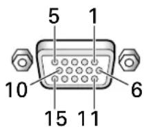
| Pin No. | Input Output | |
| 1 | R or C_R/P_R | ← |
| 2 | G or Y | ← |
| 3 | B or C_B/P_B | ← |
| 4 | NC (No connection) | ← |
| 5 | GND | ← |
| 6 | GND | ← |
| 7 | GND | ← |
| 8 | GND | ← |
| 9 | DDC + 5V | NC (No connection) |
| 10 | GND | ← |
| 11 | NC (No connection) | ← |
| 12 | DDC SDA | NC (No connection) |
| 13 | HD or H/V SYNC | ← |
| 14 | VD | ← |
| 15 | DDC SCL | NC (No connection) |
Explanation of Terms
Aspect ratio
The TV screen's width to height ratio is referred to as its aspect ratio. The aspect ratio on standard TVs is 4:3 and on wide TVs or High Definition TVs it is 16:9.
G ON SYNC
This indicates a video signal in the form of a synchronization signal added to the G (GREEN) signal of the R.G.B signal.
VGA
VGA is short for "Video Graphics Array".
Generally this indicates a 640 dot x 480 line resolution.
XGA
General term for "eXtended Graphics Array".
Generally this indicates a 1024 dot x 768 line resolution.
Apple and Macintosh are registered trademarks of Apple Computer, Inc.
Microsoft is a registered trademark of Microsoft Corporation.
NEC and PC-9800 are trademarks of NEC Corporation.
VESA and DDC are registered trademarks of Video Electronics Standards Association.
Power Management and Sun Microsystems are registered trademarks of Sun Microsystems, Inc.
VGA and XGA are registered trademarks of International Business Machines Co., Inc.
ENERGY STAR is a U.S. registered mark.
- SERIAL NO.
- Français
- Keep the safety guideline
- Do not use the monitor if it fails
- If you find something unusual,
- WARNING
- CAUTION
- SAFETY GUIDELINES(continued)
- - The enclosed power cord must be used!
- - Be careful of power cord connection!
- - Do not touch the power plug when lightning is close to you.
- - Do not touch the power plug with wet hands.
- - Do not obstruct a ventilation hole.
- - Disconnect the power plug from the mains when you move the monitor.
- - When you disconnect the power plug.
- - Disconnect the power plug from the mains when you don't use the monitor for a long time.
- - Do not put the monitor in atmosphere with soot, steam, high humidity, and dust.
- - Do not put the monitor in high temperature atmosphere.
- - Do not put things on the monitor.
- - Do not coil or wind the power cord.
- - Remove the power cord for complete isolation!
- PRECAUTIONS
- • Installation environment
- • How to view the monitor.
- • Note on image retention
- • How to clean the monitor.
- • Prevention of an obstacle to Radio receivers
- • Precautions for the monitor
- • Precaution during transportation
- • FCC (Federal Communications Commission) STATEMENT WARNING
- Declaration of Conformity
- Class B Personal Computers and
- CPU Boards and Power Supplies used
- with Class B Personal Computers:
- USER'S MANUAL
- Notes on Installation Work:
- Note for Dealers:
- Features
- ●Optional line (sold separately)
- (For details, please consult the dealer where this unit was purchased.)
- [For U.S. model]
- NOTE:
- SAFETY GUIDELINES...... I
- Before Proceeding 2
- Part Names and Functions .... 4
- Installation and Connections 8
- Setting Up the System 14
- Operations 16
- Display Panel Adjustments 21
- Other Operations 24
- Additional Information 27
- Before Proceeding
- How to Use This Manual
- About operations in this manual
- Note
- Checking Supplied Accessories
- Main Unit
- ① Remote control sensor
- ②STANDBY/ON indicator
- Operation panel on the main unit
- ③STANDBY/ON button
- ④ INPUT button
- ⑤MENU button
- ⑥ ADJUST (▲/▼/▶/◀) buttons
- ⑦SET button
- ⑧SCREEN SIZE button
- ⑨ AUTO SET UP button
- Remote Control Unit
- When handling the remote control unit
- ① SCREEN SIZE button
- ②INPUT buttons
- ③MENU button
- ④ ADJUST (▲/▼/►/◄) buttons
- ⑤SET button
- ⑥MUTING button
- ⑦ AUTO SET UP button
- ⑧STANDBY/ON button
- ⑨DISPLAY button
- ⑩POINT ZOOM button
- ⑪VOLUME (+/-) buttons
- Inserting the batteries in the remote control unit
- Operating range of the remote control unit
- If you are having difficulty with operation of the remote control unit
- Connection Panel
- ①SPEAKER (R) terminal
- ②CONTROL IN/OUT
- ③COMBINATION IN/OUT
- ④RS-232C
- ⑤INPUT1 (mini D-sub 15 pin)
- ⑥OUTPUT (INPUT1) (mini D-sub 15 pin)
- ⑦INPUT2 (BNC jacks)
- ⑧ Synchronizing signal impedance selector switch
- ⑪ MAIN POWER switch
- ⑫AC INLET
- ⑬SPEAKER (L) terminal
- Installation of the Unit
- Installation using the optional HITACHI stand or installation bracket
- Installation using accessories other than the HITACHI stand or installation bracket (sold separately)
- AUTION
- Connection to INPUT1 and INPUT2
- Connection to a personal computer \_\_\_\_
- Connection of separate SYNC analog RGB source
- When connecting to INPUT1
- When connecting to OUTPUT (INPUT1)
- Connection of G ON SYNC analog RGB source
- When connecting to INPUT2
- Connection of composite SYNC analog RGB source
- Notes
- Audio Connections
- Connecting the speakers
- Making connections to the audio inputs on this unit
- Power Cord Connection
- How to Route Cables
- Organize cables together using the provided speed clamps.
- Bunch separated cables together and secure them with the provided bead bands.
- To attach the speed clamps to the main unit
- To remove speed clamps
- Setup after Connection
- Screen Mode setup
- CLAMP POSITION setup
- Setup of CLAMP POSITION
- Press MENU to display the menu screen.
- Press ◀/▶ to select SET UP.
- Press ▲/▼ to select CLAMP POSITION.
- Press SET to select LOCKED.
- When the setup is completed, press MENU to exit the menu screen.
- Selecting an Input Source
- Before you begin, make sure you have:
- Press INPUT on the remote control unit or the main unit to select the input.
- To adjust the volume
- Press VOLUME on the remote control unit.
- To mute the sound
- Press MUTING on the remote control unit.
- To confirm display settings
- Press DISPLAY on the remote control unit.
- Screen Size Selection
- Changing the screen size
- Press SCREEN SIZE to select the size.
- Moving the screen position upward or downward
- During personal computer signal input
- ① DOT BY DOT
- ② 4:3
- ③ FULL
- ④ PARTIAL
- Partial Image Enlargement (POINT ZOOM)
- Press SET to select the zoom ratio.
- Press the remote control unit's POINT ZOOM once again to cancel the point zoom operation.
- Automatic Power OFF
- Press ◀/▶ to select SET UP. [When using INPUT 1]
- [When using INPUT 2]
- Press ▲/▼ to select either the POWER MANAGEMENT or AUTO POWER OFF mode. [When using INPUT 1]
- Press SET to confirm selection of the POWER MANAGEMENT or AUTO POWER OFF.
- When the setup is finished, press MENU to exit the menu screen.
- To return to operating mode:
- Adjusting the Picture Quality
- Press SET.
- PICTURE mode adjustment items
- To reset PICTURE mode settings to the default
- Adjusting the Image Position and Clock (Automatic Adjustment)
- Press AUTO SET UP on either the main unit or remote control unit.
- Manual Adjustment of Screen Position and Clock
- Press ◀/▶ to select SCREEN.
- Press ▲/▼ to select the adjustment item, then press SET.
- Press ◀/▶ to carry out the adjustment.
- Press SET.
- When adjustment is finished, press MENU to exit the menu screen.
- SCREEN mode adjustment items
- POSITION
- CLOCK/PHASE
- To reset SCREEN mode settings to the default
- In step 3 in the previous procedure, press ▲/▼ to select RESET, then press SET.
- Press ◀/▶ to select YES, and press SET.
- Rewriting the Input Display (INPUT LABEL)
- Power Control Function
- Press ◀/▶ to select OPTION.
- Press SET to select POWER CONTROL.
- Following completion of settings, press MENU to return to normal screen display.
- AUTO FUNCTION
- Press MENU;
- Press ▲/▼ to select AUTO FUNCTION.
- Press SET to select INPUT 1.
- Following completion of settings, press MENU again to return the display to its normal screen.
- Audio Output (AUDIO OUT)
- Press ▲/▼ to select AUDIO OUT.
- Press SET to select the desired audio level setting.
- Following completion of settings, press MENU to return to normal screen display.
- Cleaning
- Cleaning the display panel body and remote control
- Cleaning the screen
- Cleaning the vents
- Troubleshooting
- About the self diagnosis mode
- Additional cautions
- STANDBY/ON indicator
- About the plasma panel's protection function
- Panel sticking and after-image lag
- Specifications
- General
- Input/output
- Video
- Audio
- Control
- Accessories
- Supplement 1
- Supplement 2
- Explanation of Terms
- Aspect ratio
- G ON SYNC
- VGA
- XGA
Brand : HITACHI
Model : CMP5000WXU-511
Category : Screen