
E24SC - Generator HITACHI - Free user manual and instructions
Find the device manual for free E24SC HITACHI in PDF.


| Brand | Hitachi |
| Model | E24SC |
| Product Type | Portable Generator |
| Engine | Mitsubishi GT600P, Air-cooled, 4-Stroke, OHV |
| Displacement | 181 cm³ |
| Max Output (50Hz) | 2,400 W |
| Rated Output (50Hz) | 2,100 W |
| Rated Current | 9.1 A |
| Voltage | 230 V AC |
| Frequency | 50 Hz |
| Fuel Type | Regular Unleaded Gasoline (86 octane or higher) |
| Fuel Tank Capacity | 3.8 L |
| Oil Capacity | 0.6 L (SAE 10W-30 or 10W-40) |
| Starting System | Recoil Starter |
| Dimensions (L x W x H) | 563 x 455 x 415 mm |
| Dry Weight | 36 kg |
| Continuous Operation at Rated Load | 3.0 hours |
| AC Receptacle | Up to 9 A |
| Circuit Breaker | Yes, AC circuit breaker |
| Safety Features | Low Oil Alert, Overload Protection, Ground Terminal |
| Spark Plug | NGK BPR6HS (gap 0.6-0.7 mm) |
Frequently Asked Questions - E24SC HITACHI
User questions about E24SC HITACHI
0 question about this device. Answer the ones you know or ask your own.
Ask a new question about this device
Download the instructions for your Generator in PDF format for free! Find your manual E24SC - HITACHI and take your electronic device back in hand. On this page are published all the documents necessary for the use of your device. E24SC by HITACHI.
USER MANUAL E24SC HITACHI
natural_image
Exterior view of a black industrial power supply unit with motor and fan frame (no text or symbols visible)SAFETY INSTRUCTIONS AND INSTRUCTION MANUAL

WARNING
Improper and unsafe use of this generator can result in death or serious bodily injury!
This manual contains important information about product safety. Please read and understand this manual before operating the generator. Please keep this manual available for other users and owners before they use the generator. This manual should be stored in safe place.
IMPORTANT SAFETY INSTRUCTIONS FOR USING GENERATORS 3
SAFETY LABEL LOCATIONS .... 5
GROUNDING THE GENERATOR 6
REPLACEMENT PARTS 6
OPERATION AND MAINTENANCE .... 7
COMPONENTS 7
SPECIFICATIONS 8
TRANSPORTING/STORAGE 8
APPLICATIONS 8
SERVICE AND REPAIRS 17
WIRING DIAGRAM 18
ОГЛАВЛЕНИЕ
РУССКИЙ
СТРАНИЦА
IMPORTANT SAFETY INFORMATION
Read and understand all of the safety precautions, warnings and operating instructions in the Instruction Manual before operating or maintaining this generator.
Most accidents that result from generator operation and maintenance are caused by the failure to observe basic safety rules or precautions. An accident can often be avoided by recognizing a potentially hazardous situation before it occurs, and by observing appropriate safety procedures.
Basic safety precautions are outlined in the “SAFETY” section of this Instruction Manual and in the sections, which contain the operation and maintenance instructions.
Hazards that must be avoided to prevent bodily injury or machine damage are identified by WARNINGS on the generator and in this Instruction Manual.
NEVER use this generator in a manner that has not been specifically recommended by HITACHI.
MEANINGS OF SIGNAL WORDS
WARNING indicates a potentially hazardous situations which, if ignored, could result in death or serious injury.
CAUTION indicates a potentially hazardous situations which, if not avoided, may result in minor or moderate injury, or may cause machine damage.
NOTE emphasizes essential information.
SAFETY
IMPORTANT SAFETY INSTRUCTIONS FOR USING GENERATORS
READ ALL OF THE WARNINGS AND OPERATING INSTRUCTIONS IN THIS MANUAL BEFORE OPERATING OR MAINTAINING THIS GENERATOR:

natural_image
Two black-and-white icons: a warning triangle with an exclamation mark and an open book, both without any text or symbols.WARNING: Read and understand all instructions. Familiarity and proper training are required for the safe operation of generators. A generator operated improperly or by untrained personnel can be dangerous. Become familiar with all of the generator's controls, output receptacles and connections. Know how to stop generator in case of emergency. Failure to follow all instructions listed below may result in electrical shock, property damage, and/or serious personal injury or death. Do not operate the generator unless it is fully assembled.

WARNING: CARBON MONOXIDE HAZARDS
Exhaust contains poisonous carbon monoxide, a colorless and odorless gas.
Breathing exhaust can cause loss of consciousness and may lead to death.
If you run the generator in an area that is confined, or even partially enclosed the air you breathe could contain a dangerous amount of exhaust gas. To keep exhaust from building up, provide adequate ventilation. Do not operate the generator in a room, cave, or tunnel unless professionally installed exhaust hoses are used.
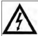
WARNING: ELECTRIC SHOCK HAZARDS
The generator produces enough electrical power to cause serious shock or electrocution if misused. Using a generator or an electrical device in wet conditions — near water, on wet grass, in damp areas, in rain or snow — could result in electrocution. Keep the generator dry at all times.
This generator is not designed to be stored outdoors unprotected from the weather.
Moisture or ice can cause a malfunction or short in electrical components, which could result in electrocution.
Check all electrical components before each use.
Do not connect this generator to any building's electrical system unless a licensed electrician has installed an isolation switch. Failure to do so can result in property damage or death.



WARNING: FIRE & BURN HAZARDS
The exhaust system gets hot enough to ignite some materials. Keep generator at least 1 (one) meter away from buildings and other equipment during or immediately after operation.
Never enclose generator in any structure. Keep all flammable materials away from the generator.
The muffler becomes very hot during operation and remains hot for some time after the engine stops. Do not touch the muffler while the engine is running or hot.
Allow the engine and the muffler to cool before storing. See storing instructions on page 8 of this manual.
Gasoline is highly flammable and poisonous. Always stop the engine and allow the muffler to cool before refueling. Never refuel while smoking or in the vicinity of an open flame or sparks. Never smoke near the generator.
Always check for spilled fuel or fuel leaks. Make sure that any spilled fuel has been wiped up before starting the generator. When operating or transporting the generator, be sure that it is kept upright. If the unit tilts, fuel may leak from the carburetor or fuel tank.
Never place your hands, fingers or other body parts near the generator's moving parts.
Never insert your fingers or other objects into the housing's ventilator. Such an action invites the danger of injuries or electric shocks.
2. NEVER USE GENERATOR FOR APPLICATIONS OTHER THAN THOSE SPECIFIED.
Never use generator for applications other than those specified in the Instruction Manual.
3. ALWAYS KEEP WORK AREA CLEAN.
Avoid injuries by not cluttering the work areas.
4. NEVER PERMIT CHILDREN OR OTHERS TO LOITER NEAR THE WORK AREA.
Keep all people (especially children) away from the work area.
5. ALWAYS WEAR PROPER APPAREL WHEN WORKING WITH THE TOOL.
Never wear loose clothing, gloves, neckties, rings, bracelets or other jewelry which may get caught in the moving parts. Always wear non-slip footwear, preferably with steel toes.
Wear protective hair covering to contain long hair.
-
When servicing this generator, use only authorized replacement parts.
-
Never operate the generator when you are tired, after you have taken any medications, or have consumed any alcoholic beverages.
-
Do not place inflammables near the generator.
Be careful not to place fuel, matches, gunpowder, oily cloths, straw, trash, or any other inflammables near the generator.
- Do not enclose the generator nor cover it with a box.
The generator has a built-in forced air cooling system, and may become overheated if it is enclosed.
- Operate the generator on a level surface.
It is not necessary to prepare a special foundation for the generator. However, the generator will vibrate on an irregular surface, so choose a level place without surface irregularities. If the generator is tilted or moved during operation, fuel may spill and/or the generator may tip over, causing a hazardous situation.
Proper lubrication cannot be expected if the generator is operated on a steep incline or slope. In such a case, piston seizure may occur even if the oil is above the upper level.
- Pay attention to the wiring from the generator to the connected device.
If the wire is under the generator or in contact with a vibrating part, it may break and possibly cause a fire or generator burnout.
- Do not operate in rain or with wet hands.
The operator may suffer severe electric shock if the generator is wet due to rain or snow.
If wet, wipe and dry it well before starting.
Do not pour water directly over the generator, not wash it with water.
- Do not operate the generator under the following condition: rainwater, seawater and salty breezes.
If the generator is used under the above condition, it may break and the operator may suffer severe electric shock.
SAFETY LABEL LOCATIONS
These labels warn you of potential hazards that can cause serious injury. Read the labels and safety notes and precautions described in this manual carefully.
SAFETY LABEL
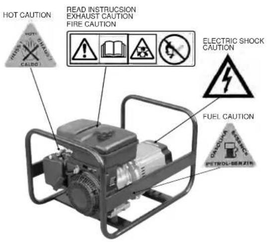
Fig. 1
GROUNDING THE GENERATOR
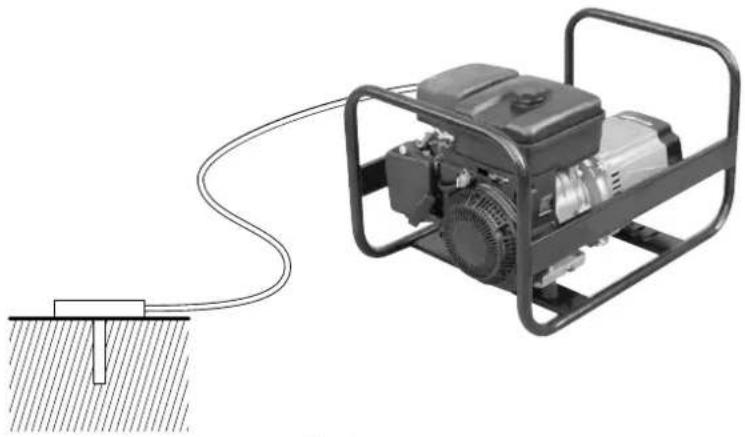
Grounding the generator helps prevent electric shock from a ground fault condition. To ground the generator you will need a ground wire and grounding stake. These are not supplied with the generator. The ground wire should be a 3.5mm^2 , stranded-copper wire. The grounding point should be copper or brass.
- Locate the ground terminal on frame.
- Attach a ground wire to the ground terminal.
- Drive the grounding point into the ground.
- Attach the ground wire to the grounding point.
WARNING: Use only grounded extension cords. Use only three wire or double-insulated power tools.
⚠ WARNING: Do not use metal pipe that is being used to carry combustible materials or gasses for the grounding point.
natural_image
Illustration of a portable electricity generator connected to a ground anchor (no text or symbols visible)Fig. 2
REPLACEMENT PARTS
When servicing use only identical replacement parts.
Repairs should be conducted only by a HITACHI authorized service center.
USE PROPER ELECTRICAL CORD
WARNING: Avoid electrical shock hazard. Never use this generator with a damaged or frayed electrical cord or extension cord. Inspect all electrical cords regularly. Never use in or near water or in any environment where electric shock is possible.
SAVE THESE INSTRUCTIONS
AND MAKE THEM AVAILABLE TO OTHER USERS
AND OWNERS OF THIS GENERATOR!
NOTE: The information contained in this Instruction Manual is designed to assist you in the safe operation and maintenance of the generator. Some illustrations in this Instruction Manual may show details or attachments that differ from those on your own generator.
COMPONENTS
Fig. 3
Fig. 4
① AC CIRCUIT BREAKER
② ENGINE SWITCH
③ AC RECEPTACLE
④ OIL FILLER CAP
⑤ OIL DRAIN PLUG
⑥ FUEL COCK
⑦ AIR CLEANER
⑧ SPARK PLUG
⑨ CHOKE LEVER
⑩ RECOIL STARTER
⑪ GROUND TERMINAL
⑫ MUFFLER
⑬ FUEL TANK CAP
SPECIFICATIONS
| ALTERNATORENGI | Model | E24SC | E42SC | E62SC | |
| Type | Brushless, Revolving Field, Self-exciting, 2-poles, Single phase | ||||
| AC Voltage | 50Hz | 230V | |||
| Max. Output | 50Hz | 2,400W | 4,200W | 6,200W | |
| Rated Output | 50Hz | 2,100W | 3,600W | 5,000W | |
| Rated Current | 9.1A | 15.7A | 21.7A | ||
| Voltage Regulator | Condenser Type | ||||
| Power Factor | 1.0 | ||||
| Model | MITSUBISHI GT600P | MITSUBISHI GM301P | MITSUBISHI GT1300P | ||
| Type | Air-cooled, 4 cycle, OHV, Gasoline Engine | ||||
| Displacement | 181cm^3 | 296cm^3 | 391cm^3 | ||
| Fuel | Regular Automobile Gasoline | ||||
| Fuel Tank Capacity | 3.8 L | 5.8 L | 5.8 L | ||
| Rated Continuous Operation | 50Hz | 3.0 h | 2.7 h | 2.1 h | |
| Lubricating Oil | Engine Oil SE Class or Higher | ||||
| Lubricating Oil Capacity | 0.6 L | 1.0 L | 1.0 L | ||
| Starting System | Recoil Starter | ||||
| DIMENSION | Length x Width x Height | 563 x 455 x 415 mm | 715 x 540 x 510 mm | 870 x 540 x 510 mm | |
| Dry Weight | 36 kg | 57 kg | 73 kg | ||
Specifications are subject to change without notice.
TRANSPORTING / STORAGE
Transporting
CAUTION: Units are heavy. Observe safe lifting procedures when transporting. Before transporting generator, it is important to turn off both the engine switch and the fuel cock. Keep generator level at all times to prevent fuel spillage. Fuel vapor or spilled fuel may ignite.
⚠ WARNING: Contact with a hot engine or exhaust system can cause serious burns or fires. Let the engine and muffler cool before transporting the generator.
CAUTION: The generator is too heavy to be lifted by one person. Obtain assistance from others before you try to move it. Otherwise, serious injury can result from attempting to lift too heavy an object.
Storage
Make sure that the generator storage area is free of excessive humidity and dust. Store the generator in dry, well-ventilated area.
⚠ WARNING: Contact with a hot engine or exhaust system can cause serious burns or fires. Let the engine and muffler cool before storing the generator.
APPLICATIONS
Power source of electric appliances and tools.
WARNING: HITACHI electronic controlled products should not be used with portable generators. Irregular generator power could cause these products to fail. Regarding other manufacturer's products, please contact the manufacturer to see if it is safe to use the electronic controlled products with portable generators.
Before starting the generator, check the oil and fuel levels. Be sure that the air cleaner is functioning. Follow the guidelines below when adding oil and fuel.
NOTE: There is no oil in the engine crankcase when the generator is shipped. You must add oil before starting the engine. Check the oil level before each use with the generator on a level surface and the engine stopped.
Engine oil is a major factor affecting engine performance and service life. Non-detergent and 2-stroke oils will damage the engine and are not recommended. Use 4-stroke motor oil that meets or exceeds the requirements for API service classification SE or Higher.
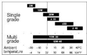
Always check the API SERVICE label on the oil container to be sure it includes the letters SE or Higher. SAE 10W-30 or 10W-40 is recommended for general, all-temperature use. Other viscosities shown in Fig.5 may be used when the average temperature in your area is within the indicated range.
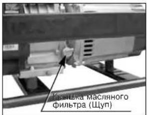
CHECKING THE OIL
- Remove the oil filler cap and wipe the dipstick clean.
- Check the oil level by inserting the dipstick into the filler neck without screwing it in.
- If the test shows no oil markings, the oil is low.
- If the level is low, add the recommended oil to the upper mark on the dipstick.
bar
| Grade | Temperature (°C) | |---|---| | Single grade | 5W | | Single grade | 10W | | Single grade | 20W | | Single grade | 400 | | Single grade | 600 | | Multi grade | 10W-30 | | Multi grade | 10W-40 | | Ambient temperature | -20 to -4 | | Ambient temperature | -10 to 14 | | Ambient temperature | 0 to 32 | | Ambient temperature | 10 to 68 | | Ambient temperature | 30 to 96 | | Ambient temperature | 40°C to 104°F |Fig. 5
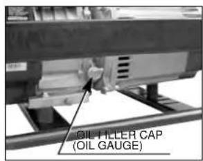
Fig. 6
OIL CAPACITY
| HITACHI Model | Liters |
| E24SC | 0.6 |
| E42SC, E62SC | 1.0 |
NOTE: If the oil level is too low, the oil alert system will shutdown the engine and prevent engine from restarting.
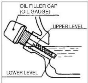
Fig. 7
FUEL
WARNING: Gasoline is flammable and its vapor is explosive. To prevent fire or explosion, follow the guidelines below:
- Keep fuel out of the reach of children.
- Refuel the generator in well-ventilated area. Do not refuel while engine is running or hot. Disconnect all electrical loads and shut off the engine before refueling.
- Do not overfill the fuel tank. Always allow room for fuel vapors to expand. If you overfill the tank, fuel can overflow onto the hot engine. This can cause fire or explosion. After refueling, tightly close the fuel tank cap.
- Do not spill fuel. Fuel or fuel vapor may ignite. If fuel spills, make sure that the area is dry before starting the engine.
- Never smoke in the refueling area. Never allow open flames or sparks in area.
- Store fuel in an approved container. Store fuel in a well ventilated area free of open flames or sparks.
FUEL TANK CAPACITY
| HITACHI Model | Liters |
| E24SC | 3.8 |
| E42SC, E62SC | 5.8 |
Check the fuel and refill the tank if the fuel level is low. Refuel carefully to avoid spilling fuel. Do not fill above the shoulder of the fuel strainer.
Use unleaded gasoline with a pump octane rating of 86 or higher.
The engine is certified to operate on unleaded gasoline.
Unleaded gasoline produces fewer engine and spark plug deposits and extends exhaust system life. Never use stale or contaminated gasoline. Avoid getting dirt or water in the fuel tank.
Always keep the fuel strainer in place while refueling.
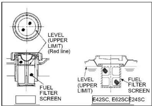
Fig. 8
OPERATION
STARTING GENERATOR
⚠ WARNING: Before starting the generator, be sure that you read and understand all the safety and operating instructions in this manual.
- Disconnect all electrical loads from the generator.
-
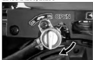
Open ("OPEN" / "O") the fuel cock.
-
Push the engine switch to the ON/I position.
-
Push the engine switch to the ON/I position.
-
Push the engine switch to the ON/I position.
-
Push the engine switch to the ON/I position.
-
Push the engine switch to the ON/I position.
-
Push the engine switch to the ON/I position.
-
Push the engine switch to the ON/I position.
-
Push the engine switch to the ON/I position.
-
Push the engine switch to the ON/I position.
-
Push the engine switch to the ON/I position.
E24SC E42SC, E62SC
natural_image
Close-up of a mechanical component with a circular dial and directional arrow indicator (no readable text or symbols)Fig. 9
E24SC E42SC, E62SC
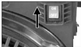
natural_image
Close-up of a car's front panel showing a button labeled 'ON' and 'OFF', with an arrow pointing to the left side (no additional text or symbols visible)Fig. 11
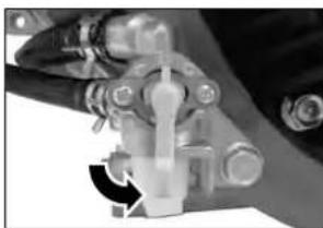
natural_image
Close-up of a mechanical component with a curved arrow indicating rotation (no visible text or symbols)Fig. 10
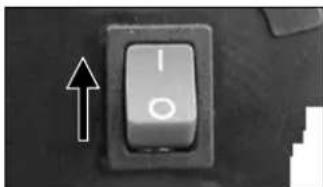
natural_image
Close-up of a black computer key with an arrow pointing to it, no visible text or symbols on the button itself.Fig. 12
-
Set the choke lever to "CLOSE" (arrow mark). Not necessary if the engine is warm.
-
Set the choke lever to "CLOSE" (arrow mark). Not necessary if the engine is warm.
-
Set the choke lever to "CLOSE" (arrow mark). Not necessary if the engine is warm.
-
Set the choke lever to "CLOSE" (arrow mark). Not necessary if the engine is warm.
-
Set the choke lever to "CLOSE" (arrow mark). Not necessary if the engine is warm.
-
Set the choke lever to "CLOSE" (arrow mark). Not necessary if the engine is warm.
-
Set the choke lever to "CLOSE" (arrow mark). Not necessary if the engine is warm.
-
Set the choke lever to "CLOSE" (arrow mark). Not necessary if the engine is warm.
-
Set the choke lever to "CLOSE" (arrow mark). Not necessary if the engine is warm.
-
Set the choke lever to "CLOSE" (arrow mark). Not necessary if the engine is warm.
E24SC
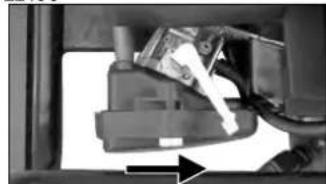
natural_image
Close-up of a mechanical component with a white plastic clip and directional arrow (no visible text or symbols)Fig. 13
E42SC, E62SC
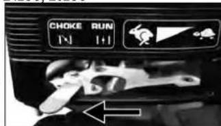
Fig. 14
- Pull the starter handle slowly until resistance is felt.
This is the "Compression" point. Return the handle to its original position and pull swiftly.
- Do not fully pull out the rope.
●After starting, allow the starter handle to return to its original position while still holding the handle.
- If the engine fails to start after several attempts, repeat above procedures with choke lever returned to "OPEN" position.
- Do not fully pull out the rope. - After starting, allow the starter handle to return to its original position while still holding the handle. - If the engine fails to start after several attempts, repeat above procedures with choke lever returned to "OPEN" position.
E24SC
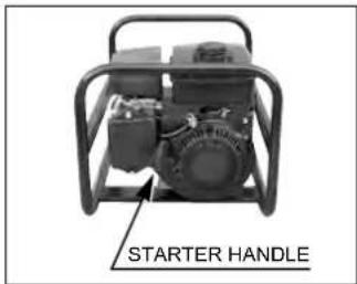
Fig. 15
E42SC, E62SC
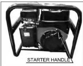
Fig. 16
- After the engine started, return the choke lever gradually to "OPEN" position.
E24SC E42SC, E62SC
natural_image
Close-up of a mechanical component with a white tool and directional arrow (no visible text or symbols)Fig. 17
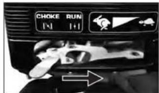
Fig. 18
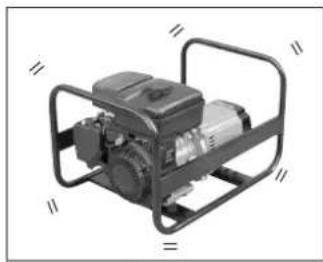
- Warm up the engine without a load for a few minutes.
natural_image
Exterior view of a portable industrial machine with control frame (no visible text or symbols)Fig. 19
NOTE: Do not allow the starter handle to snap back. Return it slowly by hand.
NOTE: If the oil level in the engine is low, the engine will not start. If the engine does not start, check the oil level and add oil as needed.
NOTE: To ensure maximum oil lubrication, place the generator on a level surface.
USING ELECTRIC POWER
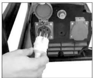
- Turn off the switch(es) of the electrical appliance(s) before connecting to the generator.
-
Insert the plug(s) of the electrical appliance(s) into the receptacle.
-
Check the amperage of the receptacles used referring to TABLE 1, and be sure not to take a current exceeding the specified amperage.
-
Be sure that the total wattage of all appliances does not exceed the rated output of the generator.
-
Turn on the switch(es) of the electrical appliances.
⚠ WARNING: Be sure to ground the generator if the connected electrical equipment is grounded.
NOTE: When the generator is overloaded, the circuit breaker will automatically activate to protect the generator and stop its output. Reduce the load to within the specified limits and reset the circuit breaker. Following this, restart the generator.
natural_image
Close-up of a hand inserting a plastic plug into an electronic device (no visible text or symbols)Fig. 20
| E24SCMODEL | E42SC E62SC | ||
 | Up to 9 ampere Up to 15 ampere Up to 15 ampere | ||
 | —— | —— | Up to 25 ampere |
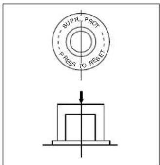
TABLE 1
Fig. 21
STOPPING THE GENERATOR
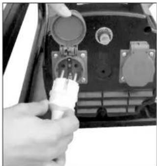
- Turn off the power switch of the electric equipment or unplug the cord from receptacle of the generator.
- Allow the engine about 3 minutes to cool down at no-load before stopping.
natural_image
Close-up of a hand inserting a white plastic plug into a black electronic device panel (no visible text or symbols)Fig. 22
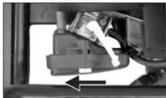
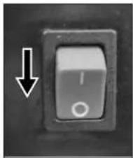
- Set the engine switch to "OFF/O" position.
E24SC E42SC, E62SC
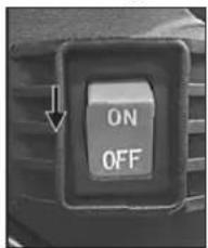
Fig. 23 Fig. 24
natural_image
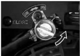
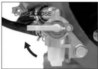
Close-up of a black toggle switch with an arrow pointing to it, no visible text or symbols- Close ("CLOSE"/ "C") the fuel cock.
E24SC E42SC, E62SC
natural_image
Close-up of a mechanical component with a blue arrow indicating rotation (no visible text or symbols)Fig. 26Fig. 25
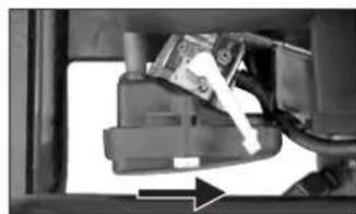
OIL SENSOR
- The oil sensor detects the fall in oil in the crankcase and automatically stops the engine when the oil level fails down below the safety limit.
- When engine has stopped automatically, check the oil level.
- If the engine does not start by usual starting procedures, check the oil level.
-Run
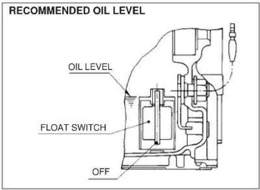
Fig. 27
-Stop
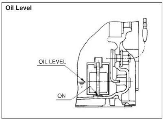
Fig. 28
SCOPE OF APPLICABILITY
It is recommended to use AC power sources within the following scope.
| Applicable instruments | Scope of applicability | Remarks | ||
| 50Hz | ||||
| Alternating current (AC) | Light, Electric Heater, Radio, Television  | E24SC | Up to 2,100W | The instruments which require much starting current and some kinds of motors may be unable to be used even if they are within the applicable scope.The breaker turns OFF when the current exceeding the applicable scope is used or when the applied instrument is defective. |
| E42SC | Up to 3,600W | |||
| E62SC | Up to 5,000W | |||
Motors with single phase 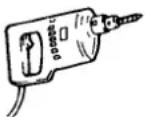 | E24SC | Up to 700W | ||
| E42SC | Up to 1,100W | |||
| E62SC | Up to 1,700W | |||
⚠ WARNING: HITACHI electronic controlled products should not be used with portable generators. Irregular generator power could cause these products to fail. Regarding other manufacturer's products, please contact the manufacturer to see if it is safe to use the electronic controlled products with portable generators.
TROUBLESHOOTING
If the engine does not start
- Check the fuel tank for sufficient fuel. Refill with fresh gasoline if necessary.
- Check the engine oil. Fill to the upper limit with fresh oil.
- Ensure that the fuel cock is open. The fuel cock is open when the lever is perpendicular to the ground (straight up and down).
- Check that the spark plug cap is securely attached to the spark plug.
- Inspect the air filter. Clean or replace it if necessary.
- Disconnect all electrical loads from the generator, and turn the engine switch on.
- Follow the starting procedures in this manual on page10.
If the engine still does not start
- Pull the starter handle 5-6 times.
- Remove and inspect the spark plug.
If the spark plug is dry:
- Ensure that there is fresh fuel in the tank and that the fuel cock is open.
- Reinstall the spark plug and spark plug cap.
- Try to start the engine again by following the starting procedures in this manual on page10.
- If the engine fails to start, take the generator to an authorized HITACHI service center.
If the spark plug is wet.
- Clean, gap, or replace the spark plug.
- Reinstall the spark plug and spark plug cap.
- Try to start the engine again by following the starting procedures in this manual on page10.
- If the engine fails to start, take the generator to an authorized HITACHI service center.
If there is no power to the receptacles
- Disconnect all electrical loads from the generator.
- Reconnect the electrical loads. Be sure that the plugs are securely connected to the receptacles.
- If there is still no power at the receptacles, take the generator to an authorized HITACHI service center.
MAINTENANCE
IMPORTANCE OF MAINTENANCE
Good maintenance is essential for safe, economical, and trouble-free operation. It will also help reduce air pollution.

WARNING: Improper maintenance or failure to correct a problem before operation can cause malfunction, serious injury, or death. Always follow the inspection and maintenance recommendation and schedules in this user's manual.
The following pages include a maintenance schedule, routine inspection procedures, and simple maintenance procedures using basic hand tools, to help you properly care for your generator. If you are not comfortable with any maintenance procedure, have the generator serviced by a professional technician.
Maintenance, replacement, or repair of the emission control devices and system may be performed by any engine repair establishment or individual, using parts that are “certified” to EU standards.
MAINTENANCE SAFETY

WARNING: Always follow the procedures and precautions in the owner's manual. Failure to properly follow maintenance instructions and precautions can lead to serious injury or death.
SAFETY PRECAUTIONS

CAUTION: Make sure that the engine is off before you begin any maintenance or repairs.
This will eliminate several potential hazards, including:
- Carbon monoxide poisoning from engine exhaust. Be sure there is adequate ventilation whenever you operate the engine.
- Burns from hot parts. Let the engine and exhaust system cool before you touch it to prevent burns.
- Injury from moving parts. Wear appropriate clothing, tie back long hair, and stay alert around the generator to prevent injury from moving parts.
Read the instructions before you begin, and make sure you have the tools and skills required.
Your authorized service center knows your generator best and is fully equipped to do maintenance and repair.
To ensure the best quality and reliability, use only new genuine parts or their equivalents for repair or replacement.

CAUTION: To reduce the possibility of fire or explosion, be careful when working around gasoline. Use only a nonflammable solvent, not gasoline, to clean parts. Keep smoking, sparks, and flames away from all fuel-related parts.
MAINTENANCE SCHEDULE
| Daily | ● Check the air cleaner● Check oil level and refill to the upper level before starting the engine.● Check all the points as follows:Fuel level at fuel gauge, Oil and Fuel leakage, Bolt and nut tighteningAny damage of components. |
| 50 hours (Weekly) | ● Clean and wash air-cleaner element.More often if used in dirty or dusty environments.● Change engine oil.(The initial oil change must be conducted after the first 25 hours operation.)● Check spark plug, and clean and adjust if necessary.● Check and clean the fuel cock. |
| 100 hours | ● Replace spark plug.● Replace air-cleaner element.○ Decarbonize cylinder head, valves and piston. |
| 3 years | ○ Inspect AC receptacle, AC circuit breaker and engine switch.○ Check rotor and stator.○ Replace engine mount rubber.○ Overhaul engine.● Change fuel lines. |
NOTE: Initial oil change should perform after first 25 hours of use. Thereafter change oil every 50 hours. Before changing oil, check for a suitable way to dispose of the old oil. Do not pour it down into sewage drains, onto garden soil or into open streams, your local zoning environmental regulations will give you more detailed instructions on proper disposal.
Items marked with a ○ required advanced skill and tools, so they should be done by the authorized HITACHI Service Center.
ENGINE OIL CHANGE
Change engine oil every 50 hours.
(for a new engine, change oil after 25 hours.)
-
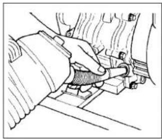
Drain oil by removing the oil drain plug and the oil filler cap while the engine is warm.
-
Reinstall the oil drain plug and fill the engine with oil unit it reaches the upper level on the oil filler cap.
- Use fresh and high quality lubricating oil to the specified quantity.
If contaminated or deteriorated oil is used or the quantity of the engine oil is not sufficient, the engine damage will result and its life will be greatly shortened.
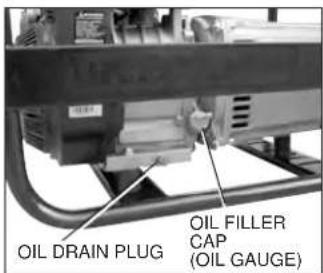
Fig. 29
natural_image
Line drawing of a hand connecting a mechanical component to a vehicle (no text or symbols)Fig. 30
Wash your hands with soap and water after handling used oil.
Please dispose of used motor oil and containers in a manner that will not harm the natural environment. We suggest you take it in a sealed container to your local service station or recycling center for reclamation. Do not throw it in the trash, pour it on the ground or down the drain.
NOTE: Never operate the generator without oil cap tightly secured. Failure to do so could cause oil to spill out of the engine.
AIR FILTER
A dirty air cleaner will restrict airflow to the carburetor. To prevent carburetor malfunction, service the air filter regularly. Service more frequently when operating the generator in extremely dusty areas.
NOTE: Never run the generator without the air cleaner. Rapid engine wear will result.
- Take out the air cleaner, clean it well in kerosene and dry it.
- After wetting the element by clean engine oil, squeeze it tight by hand.
- Lastly, put the element in the case and install it securely.
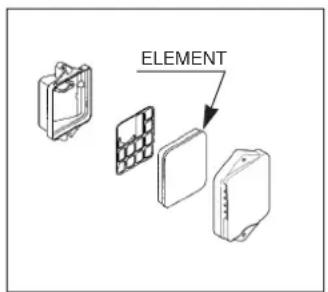
Fig. 31
CLEANING FUEL STRAINER (FUEL COCK)
E42SC, E62SC
The fuel strainer removes dirt and water in the fuel.
- Remove the strainer cup and throw away water and dirt.
- Clean the screen and strainer cup with gasoline.
- Tightly fasten the cup to main body, making sure to avoid fuel leak.
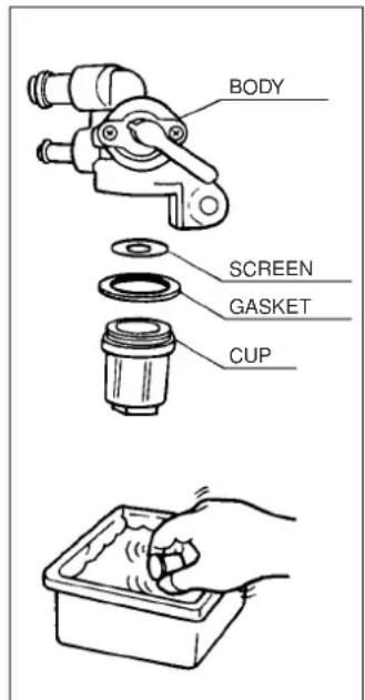
Fig. 32
SPARK PLUG SERVICE
To service the spark plug, use plug wrench (standard accessory). Use recommended spark plugs.
RECOMMENDED PLUG AND ELECTRODE CLEARANCE
| HITACHI Model | Plug | Electrode Clearance |
| E24SC | BPR6HS (NGK) | 0.6 to 0.7mm (0.024" to 0.028") |
| E42SC, E62SC | BPR5ES (NGK) | 0.7 to 0.8mm (0.028" to 0.031") |
To ensure proper engine operation, the spark plug must be properly gapped and free of deposits.

CAUTION: If the engine has been running, the muffler will be very hot. Be careful not to touch the muffler. Be sure to allow the engine to cool before you touch the spark plug.
- Remove the spark plug cap.
- Clean any dirt from around the spark plug base.
- Use a spark plug wrench to remove the spark plug.
- Visually inspect the spark plug. Replace it if the insulator is cracked or chipped.
Clean the spark plug with a wire brush if you plan to reuse it.
-
Measure the plug gap with the feeler gauge. Correct as necessary by carefully bending the side electrode (Fig.33).
-
Check that the spark plug washer is in good condition. If it is not, thread the spark plug in by hand to prevent cross threading.
-
After the spark plug is seated, tighten with a spark plug wrench to compress the washer. If you are installing a new spark plug, tighten the spark plug 1/2 turn after it seats to compress the washer. If you are reinstalling a used spark plug, tighten 1/8–1/4 turn after the spark plug seats to compress the washer.
NOTE: The spark plug must be securely tightened. An improperly tightened spark plug can become very hot and could damage the engine. Never use spark plugs which have an improper heat range. Use only the recommended spark plugs or equivalent.
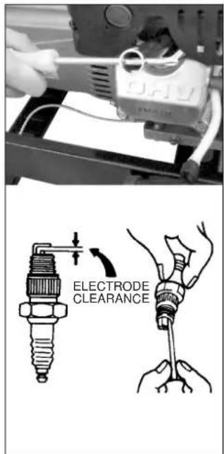
Fig. 33
PREPARATION FOR STORAGE
The following procedures should be followed prior to storage of your generator for periods of 3 months or longer.
- Drain fuel from fuel tank carefully. Gasoline left in the fuel tank will eventually deteriorate making engine-starting difficult.
- Loosen the drain screw on the bottom of the carburetor float chamber, and drain the fuel completely.
- Change engine oil.
- Check for loose bolts and screws, tighten them if necessary.
- Clean generator thoroughly with oiled cloth. Spray with preservative if available.
NEVER USE WATER TO CLEAN GENERATOR!
-
Pull starter handle until resistance is felt, leaving handle in that position.
-
Store generator in a well ventilated, low humidity area.
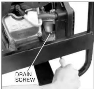
Fig. 34
SERVICE AND REPAIRS
All quality generators will eventually require servicing or replacement of parts because of wear from normal use. To assure that only authorized replacement parts will be used, all service and repairs must be performed by a HITACHI AUTHORIZED SERVICE CENTER, ONLY.
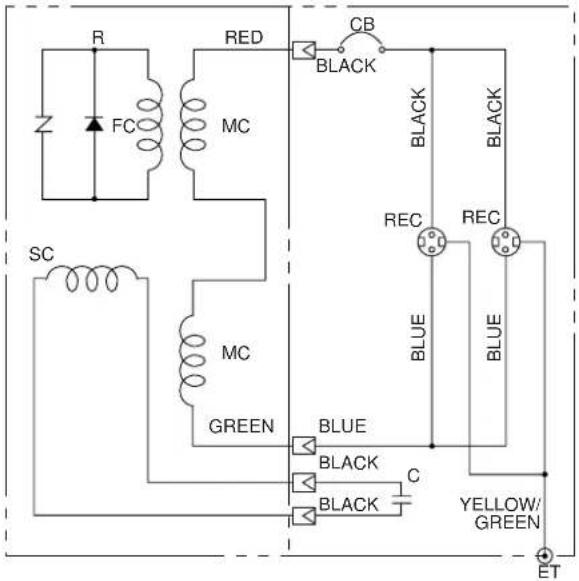
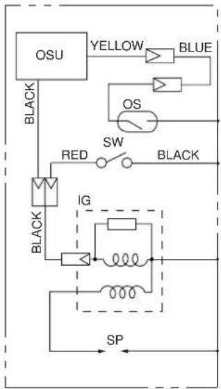
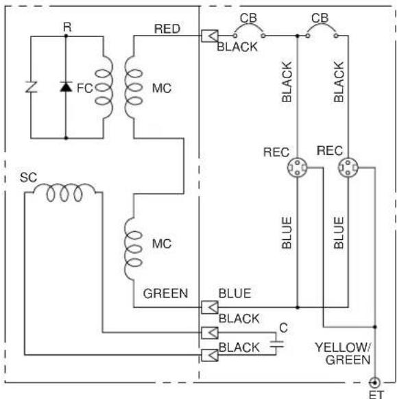
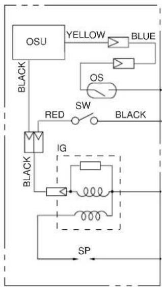
WIRING DIAGRAM
E24SC, E42SC
G/R C-BOX E/G
flowchart
graph TD
    A["OSU"] --> B["BLUE"]
    B --> C["OS"]
    C --> D["SW"]
    D --> E["BLACK"]
    E --> F["IG"]
    F --> G["SP"]
    H["BLACK"] --> I["Red"]
    I --> J["Switch"]
    J --> K["Black"]
Fig. 35
E62SC
G/R C-BOX E/G
flowchart
graph TD
    A["OSU"] --> B["BLUE"]
    B --> C["OS"]
    C --> D["SW"]
    D --> E["BLACK"]
    E --> F["IG"]
    F --> G["SP"]
    H["BLACK"] --> I["Red"]
    I --> J["Switch"]
    J --> K["Black"]
    L["Black"] --> M["IG"]
    M --> N["Switch"]
    N --> O["Black"]
Fig. 36
| Symbol | Parts Name Symbol | Parts Name | Symbol Parts Name | ||
| E/G | Engine | R | Rotor CP | CB | AC circuit breaker |
| G/R | Generator | OSU | Oil sensor unit | C | Capacitor |
| C-BOX | Control box | ET | Ground terminal | SW | Engine switch |
| MC | AC wiring | SP | Spark plug | IG | Ignition coil |
| SC | Auxiliary winding | REC | AC receptacle | ||
| FC | Field winding | OS | Oil sensor |
natural_image
Illustration of a portable electricity generator connected to a ground anchor, shown in technical sketch (no text or symbols)Fig. 2
ЗАМЕНА ЗАПЧАСТЕЙ
Fig. 3
Fig. 4
bar
| Muscle Type | Range (W) | |---|---| | Seasonal Maximum | 5W | | Seasonal Maximum | 10W | | Seasonal Maximum | 20W | | Seasonal Maximum | 30W | | Seasonal Maximum | 40W | | Seasonal Maximum | 10W-30 | | Seasonal Maximum | 10W-40 | | Seasonal Maximum | -30 | | Seasonal Maximum | -4 | | Seasonal Maximum | -10 | | Seasonal Maximum | 0 | | Seasonal Maximum | 10 | | Seasonal Maximum | 20 | | Seasonal Maximum | 30 | | Seasonal Maximum | 40 | | Seasonal Maximum | 60 | | Seasonal Maximum | 80 | | Seasonal Maximum | 100 | Theoretical maximum is -4 for Seasonal maximum and -10 for Seasonal maximum. Theoretical maximum is -30 for Seasonal maximum and -10 for Seasonal maximum. Theoretical maximum is -4 for Seasonal maximum and -10 for Seasonal maximum. Theoretical maximum is -10 for Seasonal maximum and -10 for Seasonal maximum. Theoretical maximum is -4 for Seasonal maximum and -10 for Seasonal maximum. Theoretical maximum is -10 for Seasonal maximum and -10 for Seasonal maximum. Theoretical maximum is -4 for Seasonal maximum and -10 for Seasonal maximum. Theoretical maximum is -10 for Seasonal maximum and -10 for Seasonal maximum. Theoretical maximum is -4 for seasonal maximum and -10 for seasonal maximum. Theoretical maximum is -10 for seasonal maximum and -10 for seasonal maximum. Theoretical maximum is -4 for seasonal maximum and -10 for seasonal maximum. Theoretical maximum is -10 for seasonal maximum and -10 for seasonal maximum. Theoretical maximum is -4 for seasonal maximum and -10 for seasonal maximum. Theoretical maximum is -10 for seasonal maximum and -10 for seasonal maximum. Theoretical maximum is -4 for seasonal maximum and -10 for seasonal maximum. Theoretical maximum is -10 for seasonal maximum (or seasonal minimum) and -10 for seasonal minimum (or seasonal maximum). Theoretical maximum is -4 for seasonal minimum and -10 for seasonal minimum (or seasonal maximum). Theoretical maximum is -10 for seasonal minimum and -10 for seasonal minimum (or seasonal maximum). Theoretical maximum is -4 for seasonal minimum and -10 for seasonal minimum (or seasonal maximum). Theoretical maximum is -10 for seasonal minimum and -10 for seasonal minimum (or seasonal maximum). Theoretical maximum is -4 for seasonal minimum and -10 for seasonal minimum (or seasonal maximum). Theoretical maximum is -10 for seasonal minimum and -10 for seasonal minimum (or seasonal maximum). The theoretical maximum is -4 for seasonal minimum and -10 for seasonal minimum (or seasonal maximum). The theoretical maximum is -10 for seasonal minimum and -10 for seasonal minimum (or seasonal maximum). The theoretical maximum is -4 for seasonal minimum and -10 for seasonal minimum (or seasonal maximum). The theoretical maximum is -10 for seasonal minimum and -10 for seasonal minimum (or seasonal maximum). The theoretical maximum is -4 for seasonal minimum and -10 for seasonal minimum (or seasonal maximum). The theoretical maximum is -10 for seasonal minimum and -10 for seasonality (or seasonality), the theoretical maximum is -4 for seasonal minimum and -10 for seasonality (or seasonality), the theoretical maximum is -4 for seasonal minimum and -10 for seasonality (or seasonality), the theoretical maximum is -4 for seasonal minimum and -10 for seasonality (or seasonality), the theoretical maximum is -4 for seasonal minimum and -10 for seasonality (or seasonality), the theoretical maximum is -4 for seasonal minimum and -10 for seasonality (or seasonality), or the other values are not explicitly labeled in the image.Fig. 5
natural_image
Close-up of mechanical components with no visible text or symbolsnatural_image
Close-up of a black computer key with an upward arrow indicator (no text or symbols on the key itself)Fig. 11
E24SC
natural_image
Close-up of a mechanical component with a white tool inserted, showing a curved arrow indicating direction (no text or symbols visible)Fig. 13
E42SC, E62SC
![CHOKE RUN [1] [+]](/content/2026/05/1050843/images/1edbae7d675f815a6dc0719d63601e77e4330d7f8060bcc0b016f5051b8e490c.jpg)
Fig. 14
E24SC
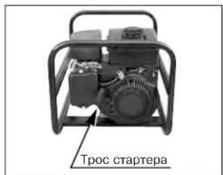
Fig. 15
E42SC, E62SC
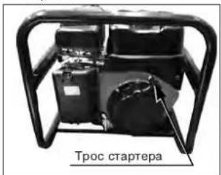
Fig. 16
natural_image
Close-up of a mechanical component with an arrow indicating direction (no visible text or symbols)Fig. 17
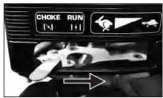
Fig. 18
natural_image
Industrial portable pump or generator device with metal frame and cylindrical body (no visible text or symbols)Fig. 19
natural_image
Close-up of a hand inserting a plug into an electronic device panel (no visible text or symbols)Fig. 20
TABLE 1
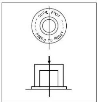
Fig. 21
natural_image
Close-up of a hand inserting a white plastic plug into a car's front panel (no visible text or symbols)Fig. 22
natural_image
Close-up of a black toggle switch with an arrow pointing to it, no visible text or symbolsnatural_image
Line drawing of a hand adjusting a mechanical component (no text or symbols visible)Fig. 30
- SAFETY INSTRUCTIONS AND INSTRUCTION MANUAL
- WARNING
- ОГЛАВЛЕНИЕ
- РУССКИЙ
- IMPORTANT SAFETY INFORMATION
- MEANINGS OF SIGNAL WORDS
- SAFETY
- IMPORTANT SAFETY INSTRUCTIONS FOR USING GENERATORS
- WARNING: ELECTRIC SHOCK HAZARDS
- WARNING: FIRE & BURN HAZARDS
- NEVER USE GENERATOR FOR APPLICATIONS OTHER THAN THOSE SPECIFIED.
- ALWAYS KEEP WORK AREA CLEAN.
- NEVER PERMIT CHILDREN OR OTHERS TO LOITER NEAR THE WORK AREA.
- ALWAYS WEAR PROPER APPAREL WHEN WORKING WITH THE TOOL.
- SAFETY LABEL LOCATIONS
- SAFETY LABEL
- GROUNDING THE GENERATOR
- REPLACEMENT PARTS
- USE PROPER ELECTRICAL CORD
- SAVE THESE INSTRUCTIONS
- AND MAKE THEM AVAILABLE TO OTHER USERS
- AND OWNERS OF THIS GENERATOR!
- COMPONENTS
- TRANSPORTING / STORAGE
- Transporting
- Storage
- APPLICATIONS
- CHECKING THE OIL
- FUEL
- OPERATION
- STARTING GENERATOR
- USING ELECTRIC POWER
- STOPPING THE GENERATOR
- OIL SENSOR
- SCOPE OF APPLICABILITY
- TROUBLESHOOTING
- MAINTENANCE
- IMPORTANCE OF MAINTENANCE
- MAINTENANCE SAFETY
- SAFETY PRECAUTIONS
- MAINTENANCE SCHEDULE
- ENGINE OIL CHANGE
- AIR FILTER
- CLEANING FUEL STRAINER (FUEL COCK)
- E42SC, E62SC
- SPARK PLUG SERVICE
- PREPARATION FOR STORAGE
- SERVICE AND REPAIRS
- WIRING DIAGRAM
- ЗАМЕНА ЗАПЧАСТЕЙ
Brand : HITACHI
Model : E24SC
Category : Generator