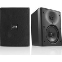
Extreme Climate M55XC - Loudspeaker Revel - Free user manual and instructions
Find the device manual for free Extreme Climate M55XC Revel in PDF.


| Product Type | Outdoor In-Wall/In-Ceiling Speaker |
| Series | Extreme Climate |
| Model | M55XC |
| Woofer Size | 5.25 inches (133 mm) |
| Tweeter Size | 1 inch (25 mm) aluminum dome |
| Frequency Response | 50 Hz - 20 kHz (-10 dB) |
| Impedance | 8 ohms nominal |
| Sensitivity | 88 dB (2.83 V @ 1 m) |
| Power Handling (Continuous) | 60 watts |
| Power Handling (Peak) | 180 watts |
| Weather Resistance | IP66 (dust-tight, water jets) |
| Enclosure Material | UV-resistant polymer with aluminum grille |
| Mounting Type | In-wall / In-ceiling with included brackets |
| Dimensions (W x H x D) | 7.3 x 10.3 x 4.5 inches (185 x 262 x 114 mm) |
| Weight | 5.5 lbs (2.5 kg) |
| Input Connectors | Gold-plated spring-loaded terminals |
| Color | White (paintable grille) |
| Warranty | 5 years limited |
Frequently Asked Questions - Extreme Climate M55XC Revel
User questions about Extreme Climate M55XC Revel
0 question about this device. Answer the ones you know or ask your own.
Ask a new question about this device
Download the instructions for your Loudspeaker in PDF format for free! Find your manual Extreme Climate M55XC - Revel and take your electronic device back in hand. On this page are published all the documents necessary for the use of your device. Extreme Climate M55XC by Revel.
USER MANUAL Extreme Climate M55XC Revel
Extreme Climate Series
Outdoor Monitors
M55XC and M80XC
Owner's Manual
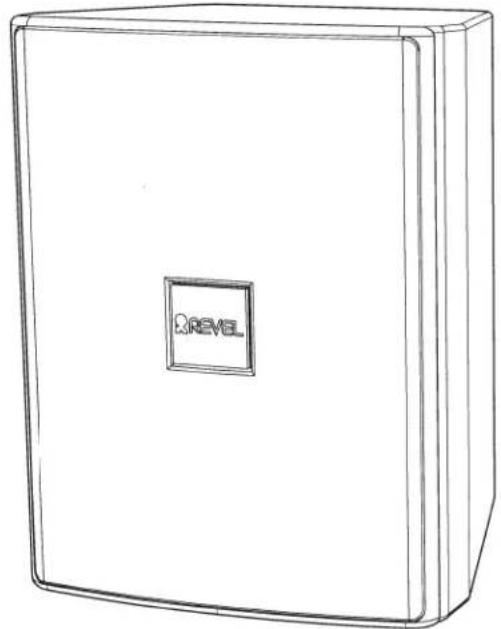
natural_image
Line drawing of a rectangular box with a 'REVEL' logo on the front face (no text or symbols on the box itself)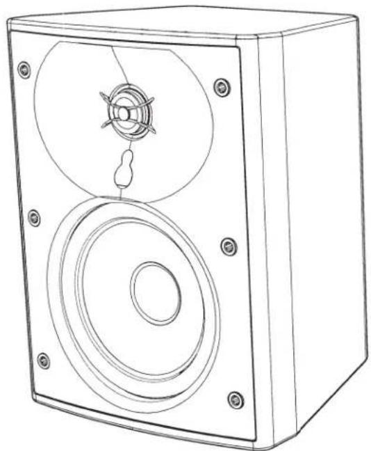
natural_image
Line drawing of a speaker chamber with two circular speakers and a central speaker (no text or symbols)IMPORTANT SAFETY INSTRUCTIONS
- Use only attachments/accessories specified by the manufacturer.
- Use only with the cart, stand, tripod, bracket, or table specified by the manufacturer or sold with the apparatus. When a cart is used, use caution when moving the cart/apparatus combination to avoid injury from tip-over.
- Refer all servicing to qualified service personnel. Servicing is required when the apparatus has been damaged in any way, such as when the power-supply cord or plug is damaged, liquid has been spilled or objects have fallen into the apparatus, or the apparatus has been exposed to rain or moisture, does not operate normally or has been dropped.
WEEE NOTICE
The Directive on Waste Electrical and Electronic Equipment (WEEE), which entered into force as European law on 14/02/2014, resulted in a major change in the treatment of electrical equipment at end-of-life.
The purpose of this Directive is, as a first priority, the prevention of WEEE, and in addition, to promote the reuse, recycling and other forms of recovery of such wastes so as to reduce disposal. The WEEE logo on the product or on its box indicating collection for electrical and electronic equipment consists of the crossed-out wheeled bin, as shown below.

This product must not be disposed of or dumped with your other household waste. You are liable to dispose of all your electronic or electrical waste equipment by relocating over to the specified collection point for recycling of such hazardous waste. Isolated collection and proper recovery of your electronic and electrical waste equipment at the time of disposal will allow us to help conserving natural resources. Moreover, proper recycling of the electronic and electrical waste equipment will ensure safety of human health and environment. For more information about electronic and electrical waste disposal, recovery, and collection points, please contact your local city center, household waste disposal service, shop from where you purchased the equipment, or manufacturer of the equipment.
ROHS COMPLIANCE
This product is in compliance with Directive 2011/65/EU of the European Parliament and of the Council of 8 June 2011 on the restriction of the use of certain hazardous substances in electrical and electronic equipment.
TABLE OF CONTENTS
About Revel Outdoor Monitors 2
Product Highlights 2
Unpacking the Loudspeakers 2
The InvisiBall™ Mounting System 3
Input Terminal Protection Cover Installation 4
Connection to the Amplifier 5
Painting the Speakers 6
Care & Maintenance....6
Specifications....6
ABOUT REVEL® XC EXTREME CLIMATE SERIES OUTDOOR MONITORS
Thank you for your purchase of Revel Extreme Climate outdoor loudspeakers. Please read this manual in its entirety to familiarize yourself with the product before attempting installation. Your XC outdoor loudspeakers have been designed to bring Revel's uncompromising and award-winning sound into the great outdoors. They offer the versatility, durability, and high-performance that an outdoor environment demands without sacrificing sound quality. Revel XC outdoor loudspeakers provide the ultimate solution for premium outdoor audio.
XC SERIES HIGHLIGHTS
- Extreme Climate (XC) design suitable for outdoor, damp, wet, or high-humidity installations
- 1-inch / 25mm Aluminum tweeter with advanced Acoustic Lens waveguide
- 5.25-inch / 130mm Carbon-infused Polypropylene cone woofer (M55XC)
• 8-inch / 200mm Aluminum cone woofer (M80XC) - 70V/100V 60W variable tap with low-impedance 8-ohm bypass
• Patented InvisiBall™ mounting system - Durable weatherized enclosure and grille with input terminal protection cover
UNPACKING THE LOUDSPEAKERS
Carefully unpack the loudspeaker. If you suspect damage from transit, report it immediately to your dealer and/or delivery service. Keep the shipping carton and packing materials for future use.
BOX CONTENTS
Your Revel XC Series Outdoor Monitors box should contain the following items:
2 x Revel XC Series Outdoor Monitors with Removable Grilles
2 x Input Terminal Weather Covers
1 x Allen Wrench
2 x InvisBall™ Wall Mount
1 x Instruction Manual
INSTALLATION CONSIDERATIONS
Revel XC outdoor loudspeakers have been engineered for optimum audio performance and durability. However, placement and positioning can have a large effect on the sound quality for a given location. Take care to locate the loudspeaker so that it is pointed towards the listening position. Ensure that the mounting system has been installed safely and properly and that the loudspeaker is not located in a position allowing it to become a hazard. With proper planning, placement, and installation, your outdoor loudspeaker will deliver years of quality service.
INVISIBALL MOUNTING SYSTEM
The InvisiBall™ is a unique method of mounting a loudspeaker. The InvisiBall™ is designed to be unobtrusive, offer theft deterrence, and simplify the installation while offering tremendous flexibility in positioning the loudspeaker.
NOTE: Your installation of this loudspeaker must be done in conformity with local building codes. Please consult with a licensed contractor or professional engineer on any installation in which the loudspeakers are mounted on a ceiling or wall. Revel is not responsible for damages resulting from the negligent installation of any bracket or loudspeaker.
- Install the InvisiBall™ mount on the wall using the screws as shown in Fig. 1. Again, be very certain that the type of anchor is appropriate for the wall material, and that the wall material will support the weight of the loudspeaker.
-
Stick a wide tipped, slotted screwdriver in the slot of the plastic InvisiBall™ knock-out plug and push downward, thereby breaking the plug out of the back of the speaker as shown in Fig. 2. Be sure the ball will fit in the hole by scraping away any residual plastic around the hole.
-
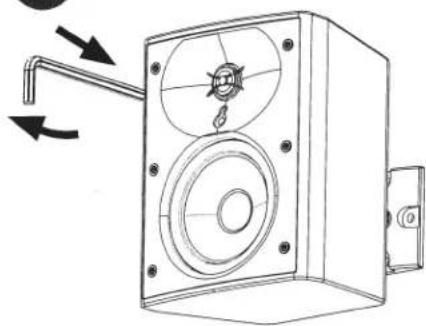
Remove the grille from the speaker enclosure to access the rubber plug located in the center between the tweeter and woofer. Pull up on the rubber plug to expose access for the Allen wrench to loosen the internal mounting clamp. The plug can be rotated to move it out of the way for the Allen wrench.
- Insert the supplied Allen wrench into the hole exposed behind the rubber plug. Lightly push and slowly rotate the Allen wrench until you feel the wrench fall into place. Loosen the InvisiBall™ clamp as shown in Fig. 4.
- Mount the speaker on the InvisiBall™ as shown in Fig. 5.
- Tighten the clamp just enough to hold the speaker while you position it in the desired orientation as shown in Fig. 6. When the speaker is pointing just the way you want it, tighten it firmly and replace the rubber plug in the hole on the speaker baffle and re-attach the grille. CAUTION: DO NOT OVERTIGHTEN.
1

natural_image
Technical line drawing of a mechanical clamp or bracket with a tool and screw (no text or symbols)Mount to wall
2

natural_image
Line drawing of a device with a switch and control panel (no text or symbols)Pop Plug
3

natural_image
Line drawing of a speaker chamber with an open lid and circular vent (no text or symbols)Remove grille
4
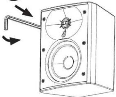
natural_image
Technical line drawing of a speaker or audio device with no visible text or symbolsOpen rubber plug, insert Allen wrench, loosen clamp
5

natural_image
Technical line drawing of a speaker with an inset close-up showing a lock mechanism (no text or symbols)Mount speaker
6
natural_image
Technical line drawing of a mechanical device with mounting bracket and circular housing (no text or symbols)Position speaker, tighten clamp, replace grille
Recommended InvisiBall Tightening Torque:
26-34 pound/inch / 30-40 kgf.cm
DO NOT OVERTIGHTEN!
INPUT TERMINAL PROTECTION COVER INSTALLATION
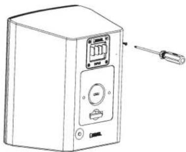
Step 1 – Remove the four (4) screws in the corners of the input terminal cup. These four screws can be set aside as they will not be reused with the protection cover.
natural_image
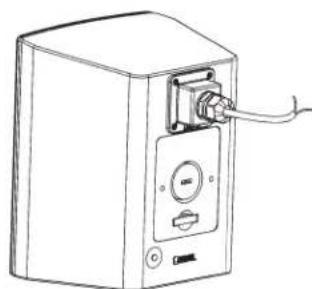
Line drawing of a portable electronic device with a screwdriver attached (no text or symbols)Step 2 – Loosen nut on the outside of the input terminal protection cover. Run the speaker cable to be connected to the terminal through the compression fitting, as shown. Do not tighten the nut on the outside of the cover yet.
Note: If you are using the compression fitting at the smaller end of its size range, it is highly recommended that you tighten and loosen the nut a few times using a wrench, to make it less stiff. Do not remove the rubber insert – it is needed for creating a watertight seal.

natural_image
Line drawing of a mechanical component with a coiled cable and connector (no text or symbols)Step 3 – Connect speaker cable to the input terminal of the loudspeaker taking care to observe proper polarity: positive (+) to positive (+) and negative (-) to negative (-). The cable leads can be connected either with bare wire (approximately 1/4-inch / 6.5mm insulation stripped from the cable) or by installing spade connectors (not included) crimped to the bare wire.

natural_image
Line drawing of a device with ports and a cable, no text or symbols presentStep 4 – Remove the protective paper over the adhesive gasket surrounding the underside of the cover. Attach the cover through the existing screw holes, using the longer screws provided with the cover. It might be necessary, depending on the stiffness of the cable, to slide the cable through the compression fitting to avoid strain on the cable or connections inside the cover.
Note: The new screws provided with the cover are longer than the screws previously removed in Step 1. Use the new screws. Do not reuse the screws previously removed in Step 1.

natural_image
Line drawing of a portable electronic device with a cable and indicator lights (no text or symbols)Step 5 – Tighten the nut on the compression fitting to seal around the cable to a recommended torque of 80 in lbs. The fitting is specified to be watertight for round cables and many off-round cables. If the fitting does not achieve a tight seal on a particular cable type, it might be necessary to use a different cable type.
natural_image
Line drawing of a portable electronic device with a cable and control panel (no text or symbols)CONNECTIONS TO THE AMPLIFIER
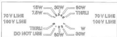
For standard amplifier hookup be sure the speaker level switch is set to "Thru (Position 5)"

Input Connections - Simply connect the amplifier's "+" and "-" outputs directly to the (+) and (-) input terminals on the back of the enclosure (see diag. 1).

natural_image
Simple line drawing of a device connected to a speaker (no text or symbols)Diagram 1.
8 Ω each – Since the loudspeakers have a rated impedance of 8Ω each, more than one speaker may be wired to one amplifier channel (see diag. 2). (See “amplifier impedance load” below.)
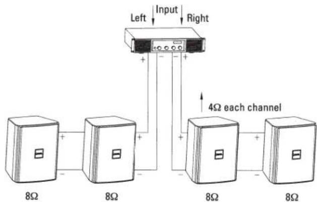
Diagram 2.
Amplifier Impedance Load - When you connect more than one loudspeaker system to an amplifier channel, either by twisting two wires together at the speaker location or via individual "home runs" from the loudspeakers to the amplifier, the load impedance to the amplifier drops. To find the maximum number of 8Ω speakers that can be wired in parallel to each channel of your power amplifier, divide 8 by the amplifier's minimum impedance load recommendation (e.g. 8Ω Revel speaker + 4R amp's minimum impedance = 2 speakers per channel, see diag. 2).
Series/Parallel - It is possible to utilize various series/parallel 'hook-up' topologies to increase the number of loudspeakers driven on an amplifier. See diag. 3 for one example of a series/parallel hook-up topology.

flowchart
graph TD
    A["Left Input"] --> B["12Ω each channel"]
    B --> C["8Ω"]
    B --> D["8Ω"]
    B --> E["8Ω"]
    C --> F["24Ω"]
    D --> F
    E --> F
Diagram 3.
Note: Mismatching the speaker impedance such that it is below the minimum impedance rating of an amplifier channel can damage the amplifier and degrade performance. If the application requires more than 2 speakers per amplifier channel wired in parallel, a distributed line system should be considered. Also check your amplifier's manual for cautions and recommendations.
Importance of Correct Polarity ("In-Phase/Out-of-Phase") - When two loudspeakers are wired with opposite polarity ("out-of-phase") relative to each other, the low frequencies of the loudspeakers cancel each other, even though the speakers are "working hard." Trying to correct the lack of bass with an equalizer can damage your loudspeakers – equalization cannot correct polarity errors. Always make sure multiple speakers are connected in proper polarity.
Distributed Line Systems - The Revel M55XC & M80XC models come equipped with built-in 70V/100V 60W variable tap transformers. Utilizing these connections requires the use of a compatible 70V/100V-capable line voltage amplifier. As with conventional 8Ω speakers, simply connect the amplifier's "+" and "-" outputs directly to the (+) and (-) input terminals on the back of the enclosure. Set the transformer tap to your desired wattage. Unlike conventional 8Ω speakers, you may connect as many XC speakers as you'd like to one amplifier channel providing that all the speaker taps do not add up to more than the amplifier's power rating (see diag. 4).
6 x 7.5 Watt = 45 Watts total load on amplifier channel

flowchart
graph TD
    A["Input"] --> B["7.5 Watt tap"]
    B --> C["7.5 Watt tap"]
    C --> D["7.5 Watt tap"]
    D --> E["7.5 Watt tap"]
    E --> F["7.5 Watt tap"]
Diagram 4.
(e.g. A 100 watt amplifier channel could safely drive 13 speakers set to 7.5 watts each, i.e. 13 × 7.5 = 97.5 < 100 ). A conservative rule-of-thumb is to try to keep the sum of the speaker loads (watts) under 3/4 of the power amp rating (e.g. A 100 watt amplifier channel will then drive 10 speakers set to 7.5 watts each, i.e. 10 × 7.5 = 75 watts).
PAINTING THE SPEAKERS
The ABS speaker enclosures of the M55XC and M80XC can be painted to match almost any decor.
Remove the grille. Mask the entire baffle, all wire terminals, and product labels. Please be careful that no tape comes in direct contact with the tweeter or woofer.
Clean the enclosures with a light solvent such as mineral spirits by rubbing the components with a lightly dampened cloth. Do not, however, use abrasives such as sandpaper or steel wool on the enclosures. Nor should you use gasoline, kerosene, acetone, MEK, paint thinner, harsh detergents or, other chemicals. Use of these cleaners may result in permanent damage to the enclosures.
After cleaning, apply two or more thin coats of either latex or oil-based paints. Latex paints will adhere better if an oil-based primer is used first. Application can be by rolling, brushing, or spraying.
The grilles require masking of the logo, and then spray painting. If the grille is rolled or brush painted, the mesh may become clogged with paint, and poor sound quality may result.
The InvisiBall™ mount may also be painted, but because it is metal, latex paints will not adhere as well as other finishes.
CARE AND MAINTENANCE
Revel XC Series Outdoor Monitors have been designed and manufactured for durability and reliable service. As with any fine product, proper maintenance and care will extend the life of the system.
You can expect your system components to perform indefinitely if you use them within their stated limits for power handling, and see that they are not abused.
Always protect the loudspeakers from over-excursion caused by strong subsonic signals (signals below 30Hz). If your amplifier has a "low cut" or "high pass" switch, engage it.
Revel XC outdoor loudspeakers are durable enough to withstand direct exposure to the elements and therefore may become dirty after some time outdoors. They can be rinsed clean with a low-pressure water stream from a garden hose or spray bottle and then dried with a soft cloth. Do not use a pressure washer or any high-pressure water streams directly on the front of the loudspeaker as the drivers could become damaged rendering the product inoperable.
SPECIFICATIONS
| FEATURE | M55XC | M80XC |
| Description | 2-way Extreme Climate Outdoor Loudspeaker | 2-way Extreme Climate Outdoor Loudspeaker |
| Enclosure Type | Sealed | Sealed |
| High Frequency Drive Components | 1-inch / 25mm Aluminum dome tweeter | 1-inch / 25mm Aluminum dome tweeter |
| Low Frequency Drive Components | 5.25-inch / 130mm Carbon-infused Polypropylene cone woofer | 8-inch / 200mm Aluminum cone woofer |
| Recommended Amplifier Power | 10-60W | 20-80W |
| Impedance | 70V / 100V 60W variable tap with 8-ohm bypass | 70V / 100V 60W variable tap with 8-ohm bypass |
| Transformer Taps | 70V: 60W, 30W, 15W, 7.5W, 8-ohm bypass100V: 60W, 30W, 15W, 8-ohm bypass | 70V: 60W, 30W, 15W, 7.5W, 8-ohm bypass100V: 60W, 30W, 15W, 8-ohm bypass |
| Sensitivity | 88dB @ 2.83V / 1m | 89dB @ 2.83V / 1m |
| Frequency Range | -3dB from 90Hz - 22kHz | -3dB from 60Hz - 22kHz |
| Low Frequency Extension | -10dB @ 60Hz, -6dB @ 74Hz, -3dB @ 90Hz | -10dB @ 45Hz, -6dB @ 52Hz, -3dB @ 60Hz |
| Crossover Frequency | 2.4kHz | 2.3kHz |
| Input Connections | Stainless Steel screw terminals | Stainless Steel screw terminals |
| Mounting | InvisiBall® mounting system | InvisiBall® mounting system |
| Dimensions H x W x D | 9.3 x 7.4 x 5.8 in (236 x 188 x 149 mm)8.0 in (200mm) deep when mounted on InvisiBall wall mount | 15 x 11 x 8.6 in (380 x 280 x 220 mm)8.0 in (200mm) deep when mounted on InvisiBall wall mount |
| Weight | 8.2 lb (3.7 kg) | 14 lb (6.4 kg) |
| Finishes | Black or White | Black or White |
| Included Accessories | Input terminal weather cover, InvisiBall wall mount, 6 x 100mm hex key | Input terminal weather cover, InvisiBall wall mount, 6 x 180mm hex key |
Features, specifications and appearance are subject to change without notice.
LIMITED WARRANTY
Revel loudspeakers are warranted against defects. The duration of a warranty depends on the laws in the country in which it was purchased. Your local Revel retailer can help you determine the duration and coverage of your warranty.
For more information please visit: REVELSPEAKERS.COM
Please visit FEVELSPEAKERS.COM for additional language support on the user manual.
HARMAN International, Incorporated
8500 Balboa Boulevard, Northridge, CA 91329 USA
© 2016 HARMAN International, Incorporated. All rights reserved.
Revel and the Revel logo are trademarks of HARMAN International Industries, Incorporated, registered in the United States and/or other countries.
Features, specifications and appearance are subject to change without notice.
For questions, assistance or additional information concerning any of our products, call us at: (516) 594-0300 or (888) 691-4171. For technical support, submit your detailed inquiry
- Extreme Climate Series
- Outdoor Monitors
- M55XC and M80XC
- Owner's Manual
- IMPORTANT SAFETY INSTRUCTIONS
- WEEE NOTICE
- ROHS COMPLIANCE
- TABLE OF CONTENTS
- ABOUT REVEL® XC EXTREME CLIMATE SERIES OUTDOOR MONITORS
- XC SERIES HIGHLIGHTS
- UNPACKING THE LOUDSPEAKERS
- BOX CONTENTS
- INSTALLATION CONSIDERATIONS
- INVISIBALL MOUNTING SYSTEM
- INPUT TERMINAL PROTECTION COVER INSTALLATION
- CONNECTIONS TO THE AMPLIFIER
- PAINTING THE SPEAKERS
- CARE AND MAINTENANCE
- LIMITED WARRANTY
Brand : Revel
Model : Extreme Climate M55XC
Category : Loudspeaker