
JackHammer JH7005 - Receiver MTX Audio - Free user manual and instructions
Find the device manual for free JackHammer JH7005 MTX Audio in PDF.


| Product Type | Car Audio Amplifier |
| Brand | MTX Audio |
| Model | JackHammer JH7005 |
| Amplifier Class | Class D |
| RMS Power (4 Ohm) | 500 W x 1 |
| RMS Power (2 Ohm) | 1000 W x 1 |
| RMS Power (1 Ohm) | 1500 W x 1 |
| Peak Power | 3000 W |
| Number of Channels | 1 (Mono) |
| Frequency Response | 20 Hz - 200 Hz |
| Input Sensitivity | 0.2 V - 8 V |
| Signal-to-Noise Ratio | > 100 dB |
| Dimensions (W x H x D) | 12.6 x 2.36 x 7.87 in (320 x 60 x 200 mm) |
| Weight | 8.8 lb (4 kg) |
| Power Supply Voltage | 12 V DC (10-16 V) |
| Fuse Rating | 150 A |
| Low Pass Filter | Variable 40-200 Hz |
| Subsonic Filter | Fixed 20 Hz |
| Bass Boost | 0-18 dB at 45 Hz |
| Remote Subwoofer Level Control | Included |
| Speaker Impedance | 1-8 Ohm |
| Heat Sink Type | Extruded aluminum |
| Protection Circuits | Thermal, short circuit, over voltage, DC offset |
| Included Accessories | Remote control, mounting hardware, user manual |
Frequently Asked Questions - JackHammer JH7005 MTX Audio
User questions about JackHammer JH7005 MTX Audio
0 question about this device. Answer the ones you know or ask your own.
Ask a new question about this device
Download the instructions for your Receiver in PDF format for free! Find your manual JackHammer JH7005 - MTX Audio and take your electronic device back in hand. On this page are published all the documents necessary for the use of your device. JackHammer JH7005 by MTX Audio.
USER MANUAL JackHammer JH7005 MTX Audio
JACKHAMMER SERIES AMPLIFIER
OWNER'S MANUAL

Use your smartphone to scan or visit youtube.com/user/MTXAudioUSA to learn how to properly install this amplifier.
PRODUCT INFORMATION
Model # ____
Serial #
Dealer's Name
Date of Purchase ____
INTRODUCTION
Thank you for purchasing this MTX Audio Hi-Performance amplifier. Proper installation matched with MTX speakers and subwoofers provide superior sound and performance for endless hours of enjoyment whether you are waking the neighbors or just out enjoying your tunes. Congratulations and enjoy the ultimate audio experience with MTX!
FEATURES
- Double Sided PCB
• Surface Mount Components - MOSFET Design
• LPF and HPF Crossover - Adjustable Bass Boost (Mono and 5-Channel)
- Auto Turn On
- Noise Free Design
- Short, Thermal, and High/Low Voltage Protection
CONTROL FUNCTIONS
- Speakers - Connect speakers/subwoofers to these terminals. Be sure to check wire for proper polarity. Never connect the speaker cables to the chassis ground.
- +BATT (+12 Volt Power) - Connect this terminal through a FUSE or CIRCUIT BREAKER to the positive terminal of the vehicle battery or the positive terminal of an isolated audio system battery. WARNING: Always protect this power cable by installing a fuse or circuit breaker of the appropriate gauge within 18 inches (45cm) of the battery terminal connection.
- Remote - This terminal turns on the amplifier when (+) 12 volt is applied to it. Connect it to the remote turn on lead of the head unit or signal source.
- GND - Connect this cable directly to the frame of the vehicle. Make sure the metal frame has been stripped of all paint down to the bare metal. Use the shortest distance possible. It is always a good idea to replace the factory ground at this time with a cable equal or larger than the new amplifier power cable. CAUTION: Do not connect this terminal directly to the vehicle battery ground terminal or any other factory ground points.
- RCA Input Jacks - These RCA input jacks are for use with source units that have RCA outputs. A source unit with a minimum level of 200mV is required for proper operation. The use of high quality twisted pair cables is recommended to decrease the possibility of radiated noise entering the system.
- Level Control - The Level, or Gain control will match the amplifier's sensitivity to the source units signal voltage. The operating range is 5V to 200mV. NOTE: This is NOT a volume control.
- Low Pass Filter Control (Mono Block) - This control is used to select the desired low pass x-over frequency. The frequency can be adjusted from 40Hz to 250Hz for all bass mono models.
- Subsonic Filter Control (Mono Block) - This control can filter out unwanted low frequency from 10Hz (OFF) to 50Hz. This function should only be used with vented enclosures.
- Bass Boost Level (Mono Block) - This can boost bass level up to 18dB. The boost frequency is centered at 45Hz.
- X-OVER (Full Range) - Selectable low pass, full range, or high pass filter controls the frequencies played for the front and rear channels.
- X-Over Frequency Control - These controls allow control over the frequencies played for the front, rear, or subwoofer channels. In LP or HP mode, the crossover frequency can be tuned from 40Hz to 250Hz.
- Auto Turn On Switch - Each model features auto turn on technology allowing installation without the use of a remote wire. If using a factory or aftermarket radio that does not include RCA outputs, the amplifier can be connected to the source unit using a speaker wire to RCA connection. The Remote Turn On switch when placed in the "Audio" position will allow the unit to turn itself on without the need to connect a remote wire. In the "Rem" position the unit will require a remote wire connection to turn on.
- Input Mode - Push button switch on multi-channel models that tells the amplifier to play in either 4-CH or 5-CH mode (JH7005) or 2-CH or 4-CH mode (JH3004).
- Input Level - Select Pre In if installing with a head unit that includes RCA outputs or Speaker Level In if installing with a factory head unit or head unit without RCA outputs.
- EBC - Input connection for external bass control that is included with mono and 5-channel models.
PANEL LAYOUT
JH3004 4-Channel Amplifier Panel Layout
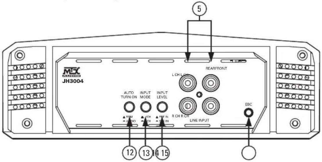


PANEL LAYOUT
JH7005 5-Channel Amplifier Panel Layout

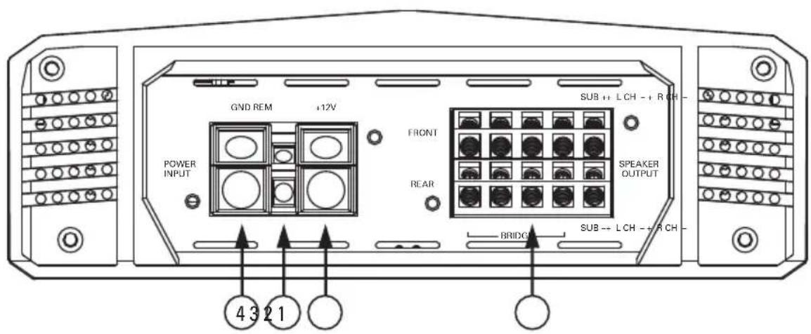

PANEL LAYOUT
JH5001 / JH10001 / JH15001 Mono Block Amplifier Panel Layout


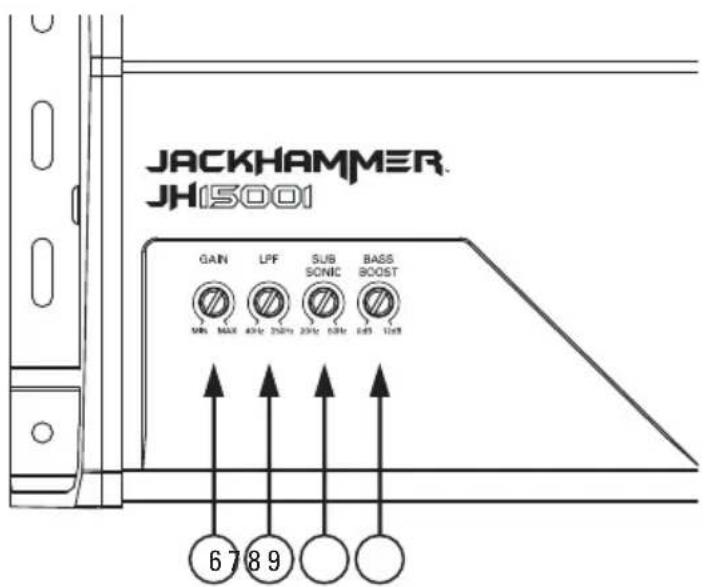
WIRING DIAGRAM
See page 28 for amplifier wiring diagrams.
INSTALLATION AND MOUNTING
MTX recommends your new JACKHAMMER amplifier be installed by a 12 volt installation specialist. Any deviation from specified installation instructions can cause serious damage to the amplifier, speakers and/or vehicle's electrical system. Damage caused from improper installation is NOT covered under warranty. Please verify all connections prior to system turn on.
- Disconnect the vehicle's negative battery cable.
- Determine the mounting place for your MTX amplifier. Keep in mind there should be sufficient air flow for proper cooling. Mark the mounting holes from the amplifier to be drilled. Before drilling make sure all vehicle wires, gas lines, brake lines and gas tank are clear and will not interfere with installation. Drill the desired holes and mount the MTX amplifier.
- Install a positive (+) power cable from the vehicle's battery through the firewall using a grommet or firewall bushing to avoid cable damage from sharp edges of the firewall. Run the cable through the interior of the vehicle and connect it to the amplifier's (+BATT) terminal. Do not connect to the battery at this time. NOTE: Use only proper gauge wire for both positive and negative connections.
- Install a circuit breaker or fuse within 18 inches of the battery. This effectively lowers the risk of severe damage to you or your vehicle in case of a short circuit or accident. Make sure the circuit breaker is switched Off or the fuse is taken out of the fuse holder until all connections are made. Now connect your positive power cable to the positive battery terminal of the battery.
- Grounding - Locate a proper ground point on the vehicle's chassis and remove all paint, dirt or debris to reveal a bare metal surface. Attach the ground wire to that contact point. Connect the opposite end of the ground wire to the (GND) terminal on the MTX amplifier.
- Connect a Remote Turn-On wire from the source unit to the MTX amplifier's (REM) terminal. If the source unit does not have a dedicated Remote Turn-On lead, you may connect to the source unit's Power Antenna lead.
- Supply the signal to your MTX amplifier by connecting the signal cables using high quality RCA to the corresponding outputs at the source unit and inputs of the amplifier.
- Connect your speakers to your MTX amplifier's speaker terminals using the correct gauge speaker wire. Your MTX amp can drive a 2Ω (JH3004 & JH7005) or 1Ω (JH5001, JH10001 & JH15001) minimum load for optimum power.
- Double check all previous installation steps, in particular, wiring and component connections. Once verified, reconnect the vehicle's negative battery cable, turn the circuit breaker On or place the fuse in the fuse holder.
NOTE: Gain Levels on the amplifier should be turned all the way down (counter clockwise) before proceeding with adjustments.
INSTALLATION
For proper performance and safety, MTX recommends installing an inline fuse per the owner's manual instructions according to the following.
| JH15001 150A Fuse (External) |
| JH10001 100A Fuse (External) |
| JH5001 60A Fuse |
| JH7005 100A Fuse |
| JH3004 50A Fuse |
TROUBLESHOOTING
| Problem Cause Solution | ||
| No LED Indication | No +12V at Remote Connection Supply | +12V to Terminal |
| No +12V at Power Connection Supply | +12V to Terminal | |
| Insufficient Ground Connection Verify | Ground Connection | |
| Blown Power Fuse Replace Fuse | ||
| Power LED On, No Output | Volume on Source Unit Off Increase Volume on Source Unit | |
| Speaker Connections Not Made Make | Speaker Connections | |
| Gain Control on Amplifier Off Turn Up Gain | ||
| Signal Processing Units Off Apply Power to Signal Processor | ||
| All Speakers Blown Replace Speakers | ||
| Output Distorted | Head Unit Volume Set Too High Lower | Head Unit Volume |
| Amplifier Gain Set Too High | Lower Amplifier Gain | |
| Balance Reversed | Speaker Wire L & R Reversed | Correct Speaker Wire Orientation |
| RCA Inputs Reversed | Reverse RCA Inputs | |
| Bass is Weak | Speakers Wired Out of Phase | Wire Speakers with Correct Phase |
| Not Using MTX Subwoofers | Buy MTX Subwoofers | |
| Blowing Fuses | Excessive Output Levels | Lower the Volume |
| Amplifier Defective | Return for Service | |
SPECIFICATIONS
| Model | JH15001 JH10001 JH5001 JH7005 JH3004 | ||||
| Description | Mono Block Class-D | Mono Block Class-D | Mono Block Class-D | Class-AB + Class-D | Class-AB |
| Primary Ratings | |||||
| Primary Power | 600W at 4Ω,20-90Hz and≤1% THD+N | 400W at 4Ω,20-150Hz and≤1% THD+N | 200W at 4Ω,20-165Hz and≤1% THD+N | 60W x 4 from20-20kHz and250W x 1 from20-150Hz at 4Ωand ≤ 1% THD+N | 60W x 4 at 4Ω,20-20kHz and≤1% THD+N |
| SNR Rating 70dBA | 68dBA 72dBA 60dBA 63dBA | ||||
| Secondary Ratings | |||||
| Dynamic Power | 650W at 4Ω,≤1% THD+N1100W at 2Ω,≤1% THD+N1650W at 1Ω,≤1% THD+N | 450W at 4Ω,≤1% THD+N775W at 2Ω,≤1% THD+N1100W at 1Ω,≤1% THD+N | 225W at 4Ω,≤1% THD+N375W at 2Ω,≤1% THD+N550W at 1Ω,≤1% THD+N | 60W x 4 at 4Ω,≤1% THD+N(Front and Rear)90W x 4 at 2Ω,≤1% THD+N(Front and Rear)180W x 2 at 4Ω,≤1% THD+N(Bridged Frontand Rear)275W at 4Ω,≤1% THD+N(Subwoofer)450W at 2Ω,≤1% THD+N(Subwoofer) | 60W x 4 at 4Ω,≤1% THD+N90W x 4 at 2Ω,≤1% THD+N180W x 2 at 4ΩBridged,≤1% THD+N |
| Frequency Response | 20Hz to 250Hz 20Hz to 250Hz 20Hz to 250Hz | 20Hz to 20kHz20Hz to 250Hz | 20Hz to 20kHz | ||
| Maximum Input Signal | 10V 10V 10V | 10V 10V | |||
| Minimum Input Signal | 135mV 135mV | 135mV 135mV 135mV | |||
| Crossover Low Pass Filter | 12dB/oct,40Hz - 250Hz | 12dB/oct,40Hz - 250Hz | 12dB/oct,40Hz - 250Hz | 12dB/oct,40Hz - 250Hz | 12dB/oct,40Hz - 250Hz |
| Crossover High Pass Filter | NA NA NA | 12dB/oct,40Hz - 250Hz | 12dB/oct,40Hz - 250Hz | ||
| Bass Boost | 0 - 12dB @ 45Hz | 0 - 12dB @ 45Hz | 0 - 12dB @ 45Hz | 0 - 12dB @ 45Hz | NA |
| Subsonic Filter | 12dB/oct,20Hz - 50Hz | 12dB/oct,20Hz - 50Hz | 12dB/oct,20Hz - 50Hz | 12dB/oct,20Hz - 50Hz | NA |
| Dimensions | |||||
| Height | 2.57" (65.2mm) | 2.57" (65.2mm) | 2.57" (65.2mm) | 2.57" (65.2mm) | 2.57" (65.2mm) |
| Width | 7.61" (193.4mm) | 7.61" (193.4mm) | 7.61" (193.4mm) | 7.61" (193.4mm) | 7.61" (193.4mm) |
| Length | 15.28" (388mm) | 12.24" (311mm) | 8.97" (228mm) | 15.47" (393mm) | 11.14" (283mm) |
WIRING DIAGRAM
Mono Block Amplifier Wiring (Single Subwoofer Load)

WIRING DIAGRAM
Mono Block Amplifier Wiring (Multi-Subwoofer Load)

NOTE: Equivalent parallel woofer load cannot be less than the minimum load rating. These are monoblock amplifiers, not multi-channel amplifiers. The minimum load for the JH15001, JH10001 and JH5001 amplifier is 1Ω. The minimum load for the Sub Channel JH7005 amplifier is 2Ω.
JH3004 Amplifier Wiring (3-Channel Mode)
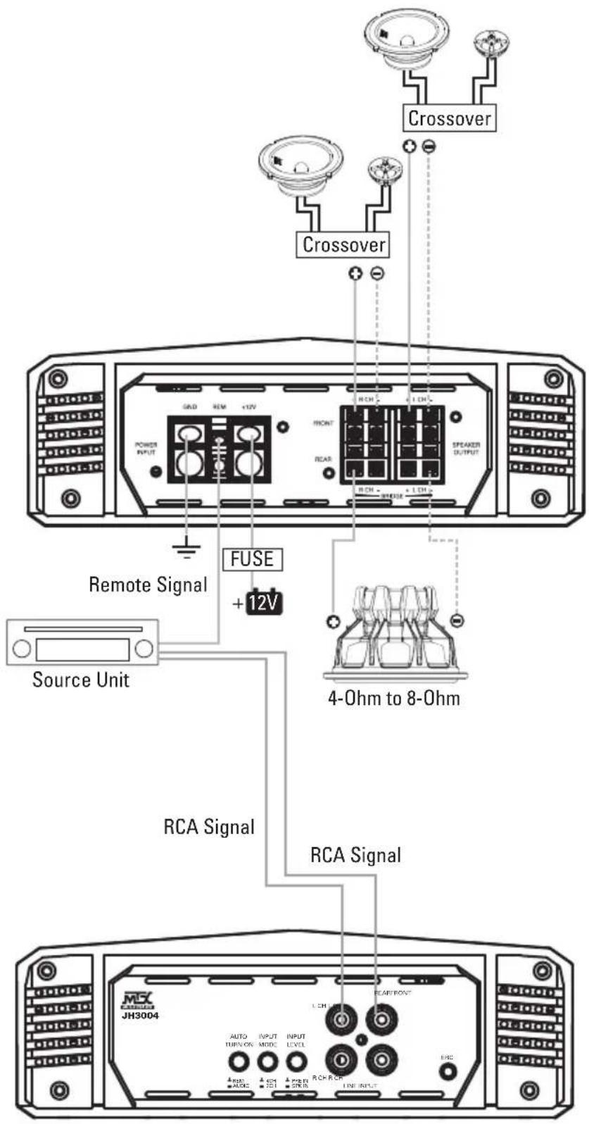
WIRING DIAGRAM
JH7005 Amplifier Wiring (5-Channel Mode)

Mitek Mobile products (including MTX, Streetwires, Coustic and Magnum) purchased in the USA after 1/1/2015 from an authorized Mitek retailer are guaranteed to be free from material defects in products and workmanship for two (2) years to the original end user purchaser, subject to the terms and conditions below.
Length of Limited Warranty and Remedy
The warranty period begins the day the product is purchased by the end user, and is limited to the original retail purchaser of the product. Products found to be defective in materials or workmanship during the first 2 years will be, at Mitek's option, repaired or replaced by Mitek at no charge. When a product is replaced during first 2 years, the warranty does not renew, it continues on from the original date of purchase.
This warranty does not cover the product if it has been subject to neglect, abuse, misuse, incorrect connection, or if it has been subject to unauthorized repair or alterations of any nature, or if the serial number has been altered or removed, and the warranty does not extend to cosmetics or finish. This warranty only applies to products installed and used in the USA.
What You Must Do to Obtain Warranty Service
You must contact Mitek Warranty via our website at MTX.com, or via email at mitekwarranty@mitekusa.com, or by calling 800-556-2888. If you did not purchase the product directly from Mitek, a proof of purchase must be provided in order to receive warranty consideration. You will be issued a Return Authorization (RA) number which must be written on the outside of the package before returning the product to Mitek. Shipping costs are the customer's responsibility when returning product to MTX.
No Other Warranties
THE LIMITED WARRANTIES DESCRIBED ABOVE ARE EXCLUSIVE AND IN LIEU OF ANY OTHER WARRANTIES, EXPRESS OR IMPLIED. MITEK DISCLAIMS AND EXCLUDES ALL OTHER EXPRESS WARRANTIES, AND DISCLAIMS AND EXCLUDES ALL WARRANTIES IMPLIED BY LAW, INCLUDING WITHOUT LIMITATION THOSE OF MERCHANTABILITY AND FITNESS FOR A PARTICULAR PURPOSE. TO THE EXTENT THAT APPLICABLE LAW PROHIBITS THE EXCLUSION OF IMPLIED WARRANTIES, THE DURATION OF ANY APPLICABLE IMPLIED WARRANTY IS LIMITED TO THE PERIOD SPECIFIED FOR THE EXPRESS WARRANTY. Some states do not allow limitations on how long an implied warranty lasts, so the above limitation may not apply to you. Any oral or written description of any Mitek product is for the sole purpose of identifying it and shall not be construed as an express warranty.
Limitation of Liability
MITEK'S OBLIGATION TO PROVIDE A CREDIT, OR REPAIR OR REPLACE AT MITEK'S OPTION, SHALL BE YOUR SOLE AND EXCLUSIVE REMEDY UNDER THIS LIMITED WARRANTY AND MITEK'S SOLE AND EXCLUSIVE OBLIGATION. MITEK SHALL NOT BE LIABLE FOR INCIDENTAL, INDIRECT, CONSEQUENTIAL OR SPECIAL DAMAGES ARISING OUT OF OR IN CONNECTION WITH THE MITEK PRODUCT, ITS USE OR PERFORMANCE. Incidental damages include, but are not limited to, such damages as loss of time and loss of use. Consequential damages include, but are not limited to, the cost of repairing or replacing other property which was damaged if the Mitek product does not work properly.
Some states do not allow the exclusion or limitation of incidental or consequential damages, so the above limitation or exclusion may not apply to you. This warranty gives you specific legal rights, and you may also have other rights, which vary from state to state. This limited warranty supersedes all prior warranties and is not transferable from the original consumer purchaser.
Any assistance Mitek provides to or procures for you outside the terms, limitations or exclusions of this limited warranty will not constitute a waiver of such terms, limitations or exclusions, nor will such assistance extend or revive the warranty. Mitek will not reimburse you for any expenses incurred by you in repairing or replacing any defective product, except for those incurred with Mitek's prior written permission.
© 2019 Mitek Corporation. All rights reserved. MTX is a trademark of Mitek Corporation. Designed and Engineered in the U.S.A.
Due to continual product development, all specifications are subject to change without notice.
MTX Audio, 4545 East Baseline Rd. Phoenix, AZ 85042 U.S.A.
MTX005827 RevC 2/19 • 21A10712 • AW0015727

N535
MX® AUDIO
JACKHAMMER

7.61" (193mm)
natural_image
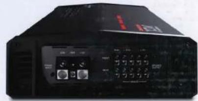
Front view of a black electronic device with control panel and indicator lights (no visible text or symbols)



WARNING:
This product can expose you to chemicals such as Styrene, which is known to the State of California to cause cancer and N-Dimethylasodamide, which is known to the State of California to cause birth defects or other reproductive harm. For more information go to www.NODemings.ca.gov
© 2019 Mtisk Corp. All rights reserved. MTX, Terminator, and Feel the Thunder are trademarks of Mtisk Corp. Due to continual product development, all specifications are subject to change without notice. MTX Audio, 4545 East Baseline Road, Phoenix, Arizona 85042 U.S.A. MTX005819 RevE 3/19

SPECIFICATIONS NEW CTA 2006-C
Class-AB + Class-D Amplifier
Primary Ratings
Primary Power Output Rating:
60W x 4 from 20-20kHz and 250W x 1 from 20-150Hz at 4Ω and ≤ 1% THD+N
SNR Rating: 60dBA
Secondary Ratings
Dynamic Power Rating:
60W x 4 at 4Ω, ≤ 1% THD+N (Front and Rear)
90W x 4 at 2Ω, ≤ 1% THD+N (Front and Rear)
180W x 2 at 4Ω, ≤ 1% THD+N (Bridged Front and Rear)
275W at 4Ω, ≤ 1% THD+N (Subwoofer)
450W at 2Ω, ≤ 1% THD+N (Subwoofer)
Frequency Response Front and Rear: 20Hz to 20kHz
Frequency Response Sub: 20Hz to 250Hz
Maximum Input Signal: 10V
Minimum Input Signal: 135mV
Crossover:
High pass 12dB/oct, 40Hz - 250Hz
Low pass 12dB/oct, 40Hz - 250Hz
Remote Bass Knob Included
Dimensions: 15.47" x 7.61" x 2.57"
ESPECIFICACIONES NUEVO CTA 2006-C
60W x 4 a 4Ω, ≤ 1% THD+N (Front and Rear)
90W x 4 a 2Ω, ≤ 1% THD+N (Front and Rear)
180W x 2 a 4Ω, ≤ 1% THD+N (Bridged Front and Rear)
275W a 4Ω, ≤ 1% THD+N (Subwoofer)
450W a 2Ω, ≤ 1% THD+N (Subwoofer)
Due to continual product improvement, all specifications are subject to change without notice.
- JACKHAMMER SERIES AMPLIFIER
- OWNER'S MANUAL
- PRODUCT INFORMATION
- INTRODUCTION
- FEATURES
- CONTROL FUNCTIONS
- PANEL LAYOUT
- WIRING DIAGRAM
- INSTALLATION AND MOUNTING
- INSTALLATION
- Length of Limited Warranty and Remedy
- What You Must Do to Obtain Warranty Service
- No Other Warranties
- Limitation of Liability
- MX® AUDIO
- JACKHAMMER
- SPECIFICATIONS NEW CTA 2006-C
- ESPECIFICACIONES NUEVO CTA 2006-C
Brand : MTX Audio
Model : JackHammer JH7005
Category : Receiver