
FP-G1-B-S - Wall socket Crestron - Free user manual and instructions
Find the device manual for free FP-G1-B-S Crestron in PDF.


| Product Type | Decorator Style Wall Socket Faceplate |
| Model | FP-G1-B-S |
| Brand | Crestron |
| Color | Black |
| Material | ABS Plastic |
| Dimensions (Approx.) | 4.5" x 2.75" (114 mm x 70 mm) |
| Depth | 0.25" (6.35 mm) |
| Weight (Approx.) | 0.1 lb (45 g) |
| Power Requirements | None (Passive) |
| Compatibility | Crestron Decorator Style Keypads (e.g., FP-G1, FP-G2, FP-G3, FP-G4) |
| Installation Method | Back plate over keypad, cover snaps into place |
| Screwless Design | Yes |
| Certifications | CE |
| Warranty | See www.crestron.com/warranty |
| Patent Information | Patents.crestron.com |
| Cleaning Instructions | Wipe with a soft, dry cloth |
| Operating Temperature | 32°F to 104°F (0°C to 40°C) |
| Storage Temperature | -4°F to 140°F (-20°C to 60°C) |
| Humidity | 0% to 90% non-condensing |
| RoHS Compliant | Yes |
Frequently Asked Questions - FP-G1-B-S Crestron
User questions about FP-G1-B-S Crestron
0 question about this device. Answer the ones you know or ask your own.
Ask a new question about this device
Download the instructions for your Wall socket in PDF format for free! Find your manual FP-G1-B-S - Crestron and take your electronic device back in hand. On this page are published all the documents necessary for the use of your device. FP-G1-B-S by Crestron.
USER MANUAL FP-G1-B-S Crestron
FP-G1/FP-G2/FP-G3/FP-G4
Decorator Style Faceplates
Installation Guide

CRESTRON®
Description
The Crestron® decorator style faceplates provide a clean finish, with no visible screws, for Crestron keypads.
Installation
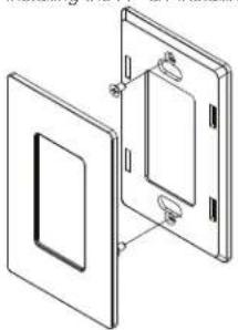
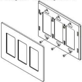
After the keypad has been installed, install the FP-G1, FP-G2, FP-G3, or FP-G4.
- Install the back plate over the keypad.
- Place the cover over the back plate. The cover snaps into place.
Installing the FP-G1 Installing the FP-G2
natural_image
Technical line drawing of two open electrical panel compartments with mounting holes (no text or symbols)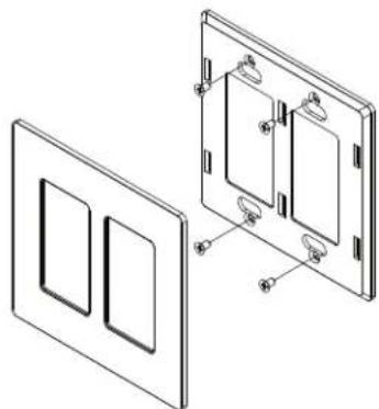
natural_image
Technical line drawing of a two-panel electrical outlet with mounting holes and internal compartments (no text or symbols)Installing the FP-G3 Installing the FP-G4
natural_image
Technical line drawing of a wall-mounted electrical panel with three rectangular cutouts and mounting holes (no text or symbols)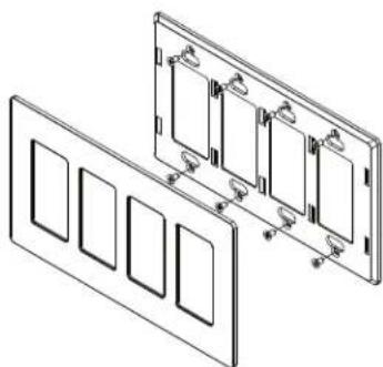
natural_image
Technical line drawing of a multi-panel electrical enclosure with mounting holes (no text or symbols)As of the date of manufacture, the device has been tested and found to comply with specifications for CE marking.
CE
Product warranty can be found at www.crestron.com/warranty.
The specific patents that cover Crestron products are listed at patents.crestron.com.
Certain Crestron products contain open source software. For specific information, please visit www.crestron.com/opensource.
Crestron and the Crestron logo are either trademarks or registered trademarks of Crestron
Electronics, Inc. in the United States and/or other countries. Other trademarks, registered
trademarks, and trade names may be used in this document to refer to either the entities
claiming the marks and names or their products. Crestron disclaims any proprietary interest in the marks and names of others. Crestron is not responsible for errors in typography or photography.
This document was written by the Technical Publications department at Crestron.
©2016 Crestron Electronics, Inc.
Crestron Electronics, Inc. Installation Guide - DOC. 7445A
15 Volvo Drive Rockleigh, NJ 07647 (2034888)
Tel: 888.CRESTRON 11.16
Fax: 201.767.7576 Specifications subject to
www.crestron.com change without notice.
Brand : Crestron
Model : FP-G1-B-S
Category : Wall socket