
VRS - Support de montage en rack Middle Atlantic - Free user manual and instructions
Find the device manual for free VRS Middle Atlantic in PDF.


| Product Type | Power Distribution Unit (PDU) |
| Brand | Middle Atlantic |
| Model | VRS |
| Form Factor | 19-inch Rackmount, 1U |
| Dimensions (H x W x D) | 1.75 x 19.0 x 10.0 inches (44.5 x 483 x 254 mm) |
| Weight | 5.0 lbs (2.3 kg) |
| Input Voltage | 120V AC |
| Input Current | 15A |
| Output | 8 NEMA 5-15R outlets |
| Surge Protection | 1200 Joules |
| Power Cord | 6 ft (1.8 m) with NEMA 5-15P plug |
| Mounting | Horizontal or vertical with included brackets |
| Front Panel | Illuminated power switch and resettable circuit breaker |
| Indicators | Power LED (green), Surge Protection LED (red/green) |
| Material | Steel chassis with black powder coat finish |
| Cooling | Passive vented design |
| Compliance | UL, cUL listed |
| Operating Temperature | 32°F to 104°F (0°C to 40°C) |
| Warranty | 2 years limited |
| Cleaning | Use a dry, lint-free cloth. Do not use liquids or solvents. |
| Safety | Ensure proper grounding. Do not exceed rated load. Unit is sealed; no user-serviceable parts. |
Frequently Asked Questions - VRS Middle Atlantic
User questions about VRS Middle Atlantic
0 question about this device. Answer the ones you know or ask your own.
Ask a new question about this device
Download the instructions for your Support de montage en rack in PDF format for free! Find your manual VRS - Middle Atlantic and take your electronic device back in hand. On this page are published all the documents necessary for the use of your device. VRS by Middle Atlantic.
USER MANUAL VRS Middle Atlantic
natural_image
Stacked server rack with multiple white rack-mounted units and ventilation grilles, no visible text or labelsTHANK YOU
Thank you for purchasing the VRS Vertical Rackmount System. Please read these instructions thoroughly before installing/assembling this product.
PRODUCT FEATURES
- Adjustable rackmount system allows easy placement of cable boxes in a vertical position
- Cable boxes are clamped in place and evenly spaced, using adjustable plastic spacers in the top and bottom shelves
- Can hold up to 7 components such as satellite or cable boxes, depending on size
- Permits space between the units which allows for ventilation
NOTE: Most cable and satellite receivers are designed to be mounted horizontally. Special Consideration must be given to proper thermal management when mounting vertically
SUPPLIED HARDWARE
| (A) | Plastic Spacer 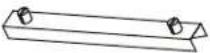 | QTY 22 |
| (B) | 8-32 Nuts | QTY 3 |
| (C) | 8-32 Studs | QTY 3 |
| (D) | Rear Retainer Bar (Used for Transportation) | QTY 1 |
| (boral) | Front Retainer Bar (Used for Transportation) | QTY 1 |
1) PRE-INSTALLATION SIZING/REAR RETAINER BAR INSTALLATION
Place the rackshelf onto a flat surface. Place your first and last cable boxes onto the rackshelf as shown. Slide the boxes until they are flush with the front rackears. This is to determine where to place the rear retainer bar, which will secure the components from the back. (FIGURE A)

FIGURE A
INSTALLATION CONTINUED
2) SECURE REAR RETAINER BAR
Position the rear of the components flush with the front ears. Secure the rear retainer bar using the supplied hardware as shown. (FIGURE B)
NOTE: If using the front retainer bar, do not fully tighten rear retainer bar hardware

natural_image
Technical line drawing of a mechanical component with two views (Figure B), showing internal structure and mounting features without any text or symbols.Once the rear retainer bar is installed, remove the boxes to mount the shelf to the rackrail.
4) INSTALL BOTTOM RACKSHELF
Install to rackrail as shown. (FIGURE C)

NOTE: The lip of the rackshelf aligns with the bottom of the lowest rackspace (to equal two rackspaces because the ear alone is less than two rackspaces)
INSTALLATION CONTINUED
5) INSERT THE FIRST COMPONENT
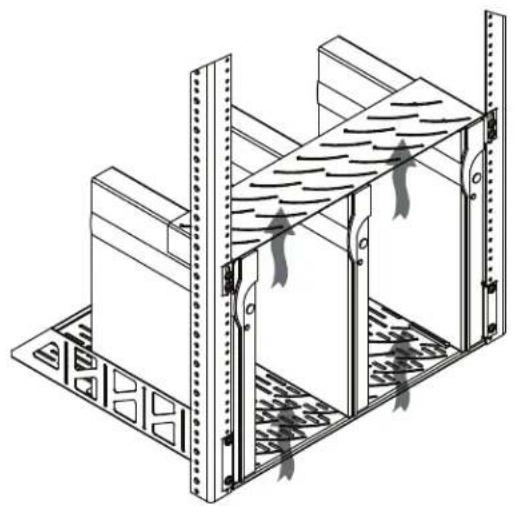
Place the first component onto the shelf at one end. (FIGURE D)

natural_image
Technical line drawing of a server rack unit with mounting brackets and ventilation grilles (no text or symbols)NOTE: If not filling the shelf completely, space the units apart as shown for best ventilation
natural_image
Isometric line drawing of a structural frame with vertical supports and internal channels (no text or symbols)6) INSERT BOTTOM SPACERS
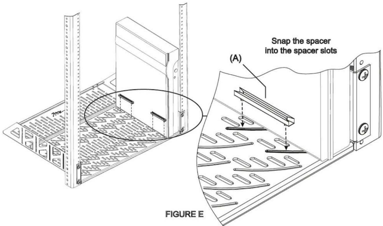
Insert the first pair of plastic spacers into the bottom shelf spacer slots by snapping them in as shown. (FIGURE E)
INSTALLATION CONTINUED
7) SECURE BOTTOM SPACERS
Slide the first pair of spacers against the component for a tight fit as shown. (FIGURE F)

natural_image
Technical line drawing showing two mechanical assembly steps with directional arrows indicating motion (no text or symbols)FIGURE F
8) TOP INSTALLATION
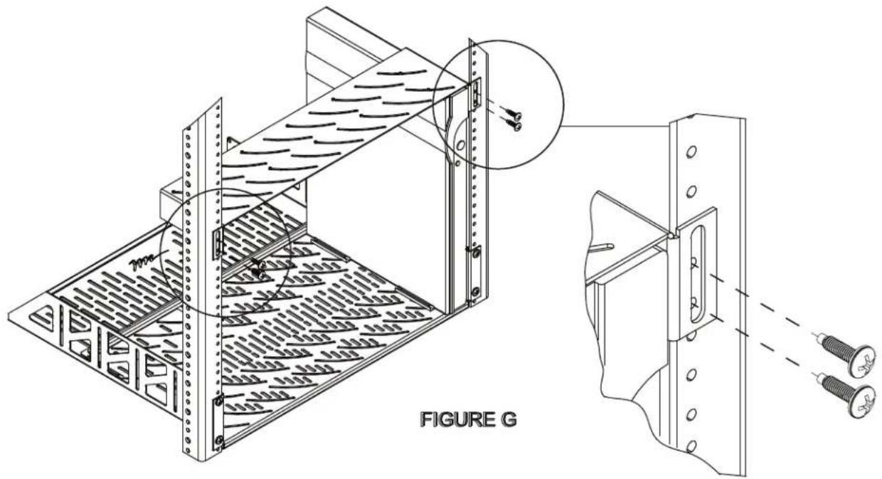
Install the top over the first component as shown. (FIGURE G)
NOTE: Leave the top shelf screws loosely assembled until all components are installed.
natural_image
Technical line drawing of a mechanical assembly with labeled components and a magnified inset showing two screws (no text or symbols present)INSTALLATION CONTINUED
Invert the spacer and insert it into the top as shown.. (FIGURE H)

10) SECURING TOP SPACERS
Secure each spacer by sliding it against each component for a tight fit. (FIGURE J)

natural_image
Technical diagram of a mechanical component with directional arrows indicating flow or motion (no text or symbols)FIGURE J
INSTALLATION CONTINUED
Install all remaining components and spacers as required. Repeat previous installation steps until all components and spacers are in place.
12) INSTALLATION OF FRONT RETAINER BAR (OPTIONAL)
Install front retainer bar as shown. Ensure the side with the foam is facing the components. Push rear retainer bar against components until the foam on the front retaining bar and fully tighten rear retainer bar hardware. (FIGURE K)

natural_image
Technical line drawing of a server rack unit with mounting brackets and internal panel structure (no text or symbols)FIGURE K
13) SECURE TOP SHELF
Once all components have been installed, gently apply even pressure to the top and tighten the rackscrews to secure. (FIGURE L)

FIGURE L
OPTIONS
POWER STRIP
- The VRS is shown with a 15 Amp 8 outlet slim surge-protected power strip with tool-less, two-position mounting bracket
- Part Number PD-815SC-PBSH
NOTE: THERMAL MANAGEMENT IT IS THE INSTALLERS RESPONSIBILITY TO PROVIDE ADEQUATE HEAT REMOVAL ABOVE THE VRS SYSTEM TO ENSURE EQUIPMENT RELIABILITY

WARRANTY
Middle Atlantic Products, Inc. (the "Company") warrants the VRS Series Vertical Rackmount System to be free from defects in material or workmanship under normal use and conditions for the lifetime of the product.
The Company's entire liability to the purchaser, and the purchaser's (or any other party's) sole and exclusive remedy, under this warranty shall be limited, at the Company's option, to either (a) return of and refund of the price paid for, or (b) repair or replacement at the Company's factory of the products purchased, or any part or parts thereof, which the Company has determined to be defective after inspection thereof at the Company's factory. This warranty does not cover damage due to acts of God, accident, misuse, abuse or negligence by parties other than the Company, or any modification or alteration of the products. In addition, this warranty does not cover damage due to improper handling, assembly, installation or maintenance.
THIS WARRANTY IS IN LIEU OF ALL OTHER WARRANTIES OF ANY KIND, EITHER EXPRESSED OR IMPLIED, INCLUDING, BUT NOT LIMITED TO, IMPLIED WARRANTIES OF MERCHANTABILITY AND FITNESS FOR A PARTICULAR PURPOSE.
TO THE MAXIMUM EXTENT PERMITTED BY APPLICABLE LAW, IN NO EVENT SHALL THE COMPANY BE LIABLE FOR ANY SPECIAL, INCIDENTAL, INDIRECT, OR CONSEQUENTIAL DAMAGES WHATSOEVER (INCLUDING WITHOUT LIMITATION, DAMAGES FOR LOSS OF BUSINESS PROFITS, BUSINESS INTERRUPTION OR ANY OTHER PECUNIARY LOSS) ARISING OUT OF THE USE OF THE PRODUCTS PURCHASED, EVEN IF THE COMPANY HAS BEEN ADVISED OF THE POSSIBILITY OF SUCH DAMAGES. THE COMPANY'S LIABILITY TO THE PURCHASER (OR ANY OTHER PARTY) HEREUNDER, IF ANY, SHALL IN NO EVENT EXCEED THE PURCHASE PRICE OF THE PRODUCTS PAID TO THE COMPANY.
Corporate Headquarters
Corporate Voice 973-839-1011 - Fax 973-839-1976 / International Voice +1 973-839-8821 - Fax +1 973-839-4982
middleatlantic.com - info@middleatlantic.com
Middle Atlantic Canada
Voice 613-836-2501 - Fax 613-836-2690 / middleatlantic.ca - customerservicecanada@middleatlantic.ca
Factory Distribution
USA: NJ - CA - IL Canada: ON - BC
At Middle Atlantic Products we are always listening. Your comments are welcome.
Middle Atlantic Products is an ISO 9001 and ISO 14001 Registered Company.

- THANK YOU
- PRODUCT FEATURES
- 1) PRE-INSTALLATION SIZING/REAR RETAINER BAR INSTALLATION
- INSTALLATION CONTINUED
- 2) SECURE REAR RETAINER BAR
- 4) INSTALL BOTTOM RACKSHELF
- 5) INSERT THE FIRST COMPONENT
- 6) INSERT BOTTOM SPACERS
- 7) SECURE BOTTOM SPACERS
- 8) TOP INSTALLATION
- 10) SECURING TOP SPACERS
- 12) INSTALLATION OF FRONT RETAINER BAR (OPTIONAL)
- 13) SECURE TOP SHELF
- OPTIONS
- POWER STRIP
- WARRANTY
- Corporate Headquarters
- Middle Atlantic Canada
- Factory Distribution
Brand : Middle Atlantic
Model : VRS
Category : Support de montage en rack