
REB18 - Electronic equipment accessory Middle Atlantic - Free user manual and instructions
Find the device manual for free REB18 Middle Atlantic in PDF.


| Product Type | Rotating Sliding Base |
| Brand | Middle Atlantic |
| Model | REB18 |
| Maximum Load Capacity | 75 lbs (cantilever load) |
| Mounting Surface Requirement | Must support cantilever load; pilot holes with 3/32" drill bit recommended |
| Rotation Direction | Adjustable (default left); switch by moving set screw to opposite side |
| Locking Mechanism | Thumbscrews to secure closed position |
| Included Hardware | #10x5/8 wood screws (6), #6x1/2 wood screw (2), hook and loop fasteners (12 pairs), hook and loop straps (2), adhesive backed cable managers (2), wire ties (6), 1"x2" loop fastener (2), rotation label (1) |
| Cable Management | Yes; straps, cable managers, wire ties for neat organization |
| Component Attachment | Hook and loop fasteners on component feet |
| Warranty | 3 years from shipment, defects in material or workmanship |
| Installation Tools Required | Drill with 3/32" bit (pilot holes), screwdriver |
| Compliance | ISO 9001 and ISO 14001 registered |
Frequently Asked Questions - REB18 Middle Atlantic
User questions about REB18 Middle Atlantic
0 question about this device. Answer the ones you know or ask your own.
Ask a new question about this device
Download the instructions for your Electronic equipment accessory in PDF format for free! Find your manual REB18 - Middle Atlantic and take your electronic device back in hand. On this page are published all the documents necessary for the use of your device. REB18 by Middle Atlantic.
USER MANUAL REB18 Middle Atlantic
natural_image
Technical line drawing of a rectangular electronic component labeled REB14, with mounting holes and a central dot (no text or symbols on the diagram itself)
natural_image
Isometric line drawing of a rectangular electronic component with mounting holes and a central circular feature, labeled 'REB18' (no other text or symbols)THANK YOU
Thank you for purchasing the REB Series Rotating Sliding Base. Please read these instructions thoroughly before installing this product.
PRODUCT FEATURES
- Provides easy access to rear equipment connections and cables
- Locks closed to prevent unintentional opening
- Included accessories to manage cables and keep wires neat and organized
PARTS
HOOK AND LOOP FASTENERS

HOOK
(Coarse Material)

LOOP (Soft Material)
QTY
12 (each)
#10x5/8 WOOD SCREWS

QTY
6
#6x1/2 WOOD SCREW

QTY
2
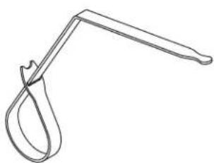
HOOK AND LOOP STRAP
natural_image
Line drawing of a hand tool with a curved handle and loop (no text or symbols)QTY
2
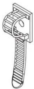
ADHESIVE BACKED CABLE MANAGERS
QTY
2
WIRE TIE

QTY
6
1"x2" LOOP FASTENER

QTY
2
ROTATION LABEL

QTY
1
(Right Rotation)
(Left Rotation)
SPECIFICATIONS

Mounting surface MUST be able to support cantilever load, maximum load is 75 lbs.

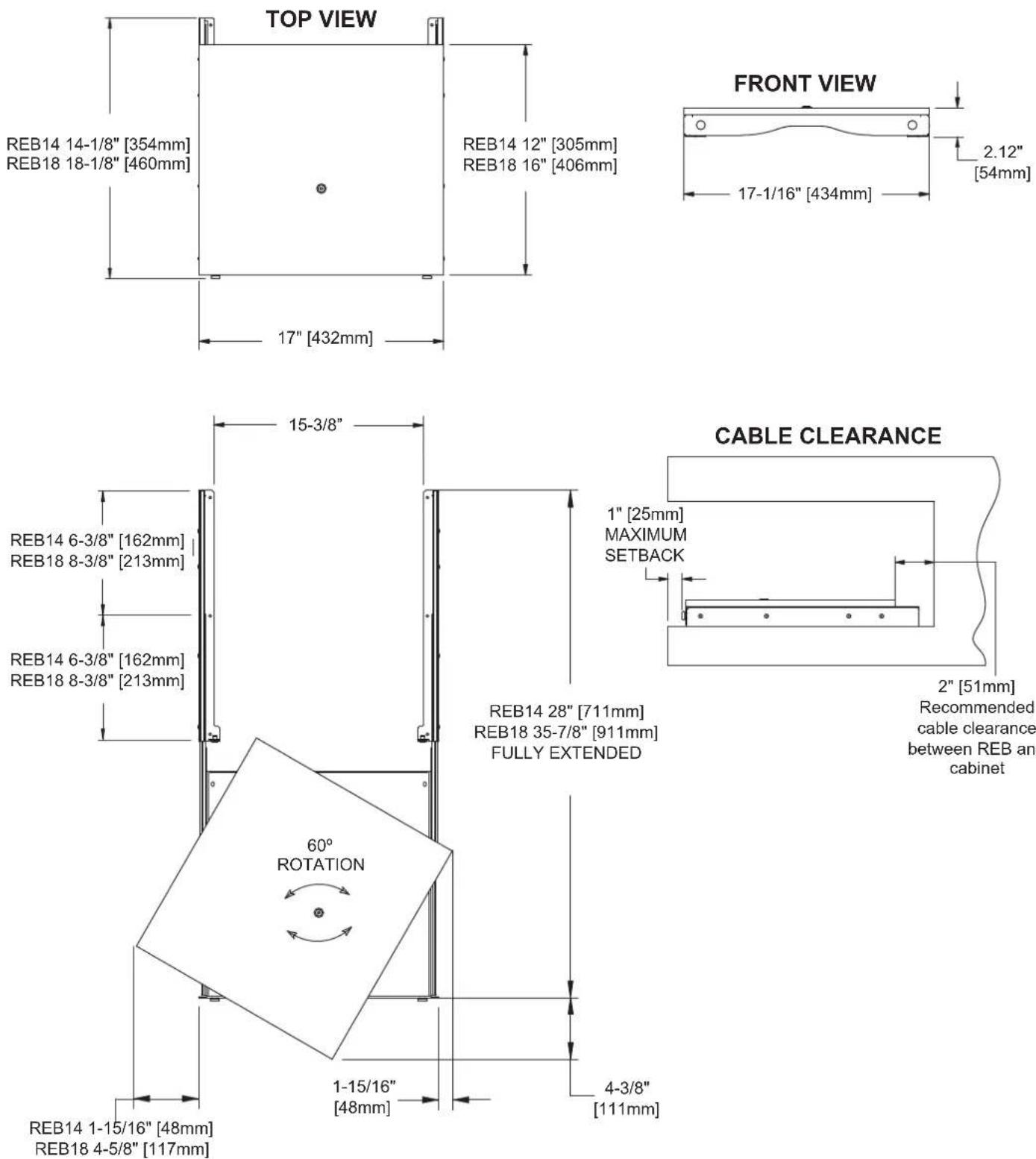
SHOWN FULLY EXTENDED AND ROTATED 60°
INSTALLATION
1) Determine rotation direction (Default rotation is to the left). To switch rotation, turn over and move Set Screw to opposite side. (FIGURE A)
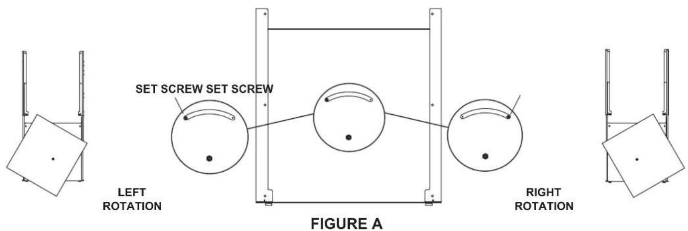
2) Place in desired location with Thumbscrews in secured position (This ensures a square installation). Check clearance and setback for door closure, room for cables, etc.
3) If required, mark exposed mounting holes in the back of the rails and remove REB. Drill pilot holes with 3/32" drill bit. (FIGURE B)

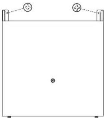
4) Place REB back in desired location. Affix to surface using provided #10x5/8 Wood Screws. (FIGURE C)
natural_image
Simple line drawing of a rectangular container with two vertical supports and two circular symbols on top (no text or labels)FIGURE C
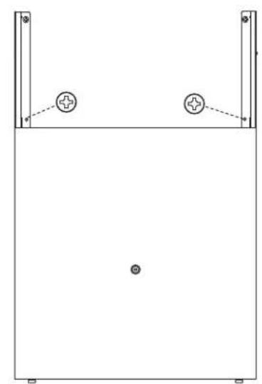
5) Loosen Thumbscrews and extend to next set of mounting holes. Install two #10x5/8 Wood Screws. If required, drill pilot holes using 3/32" drill bit. (FIGURE D)
6) Fully extend and install remaining 10x5/8 screws (six total screws, three per slide). If required, drill pilot holes using 3/32" drill bit. (FIGURE E)
natural_image
Simple line drawing of a rectangular frame with two vertical supports and two circular markers on the top (no text or symbols)FIGURE D

natural_image
Pure technical line drawing of a mechanical or architectural component with two vertical supports and two circular features at the base (no text or symbols)FIGURE E
7) With REB fully extended, determine location of components.
8) Place components on base and verify clearance of knobs, doors, etc.
9) Remove components.
10) Turn the bottom component over.
11) Remove adhesive backing on 7/8" Loop Fastener.
12) Place Loop Fastener on solid portion of component's feet. If no feet are on the component, place on flat locations as close to the corners as possible. (FIGURE F)
13) Attach 7/8" Hook Fastener to Loop Fastener. Remove backing. (FIGURE G) Hook and Loop Fasteners ensure component(s) are secure on REB.
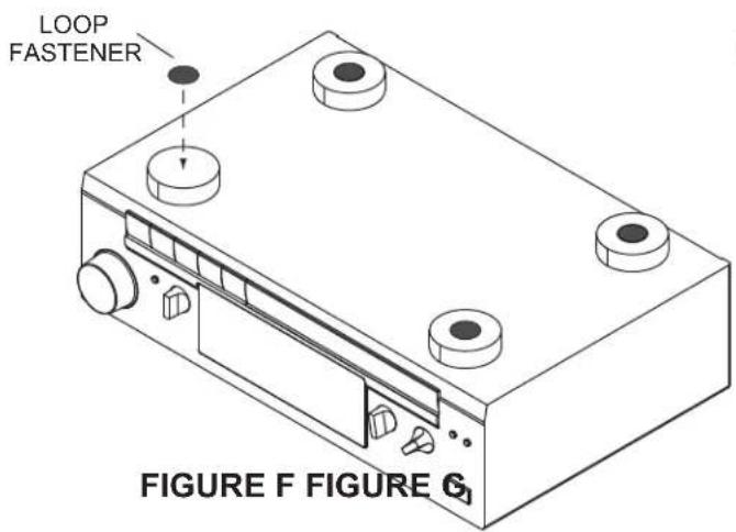

14) Turn component over and place on predetermined location on the REB. Gently press down on component to adhere. (FIGURE H)
15) Repeat steps 10-14, stacking components one on top of the other. (FIGURE J)

natural_image
Isometric line drawing of a device with labeled components and directional arrows, no readable text or symbols present.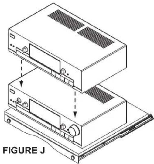
natural_image
Technical line drawing of two stacked electronic devices with ventilation slots and connectors, labeled as FIGURE J (no text or symbols on the devices themselves)17) Route cabling to cabinet exit point.
18) Install 1"x2" Loop Fastener in appropriate location. Do not cover vents on component. (FIGURE J)
19) Wrap Hook and Loop Strap(s) around cables. Attach to 1"x2" rectangular Loop as shown. (FIGURE K) A second Hook and Loop Strap and 1"x2" Loop Fastener are provided for cabling needs. (Heavy cable bundles, etc.)
NOTE: When placing cabling in strap, keep cables as high as possible.

20) Using provided Wire Ties, bundle cabling approximately every 6" to 8".
21) Remove backing from Adhesive Backed Cable Manager and mount to highest possible location on the opposite side of Hook and Loop Strap(s). (FIGURE L)
NOTE: If host enclosure allows, use provided #6x1/2 Wood Screws to secure Adhesive Backed Cable Manager(s).
22) Install cabling to Adhesive Backed Cable Manager(s).
23) Open, rotate and close REB to ensure proper operation. Adjust cabling if required.
24) Place Rotation Label on top component to show rotation direction.
25) Close REB and turn Thumbscrews to secure in place.
ADHESIVE BACKED CABLE MANAGERS
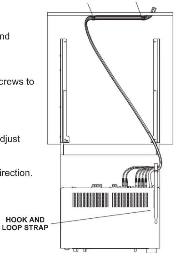
FIGURE L
WARRANTY
Middle Atlantic Products (the "Company") warrants the REB Series Rotating Equipment base to be free from defects in material or workmanship under normal use and conditions for a period of (3) three years from date of shipment by company.
The Company's entire liability to the purchaser, and the purchaser's (or any other party's) sole and exclusive remedy, under this warranty shall be limited, at the Company's option, to either (a) return of and refund of the price paid for, or (b) repair or replacement at the Company's factory of the products purchased, or any part or parts thereof, which the Company has determined to be defective after inspection thereof at the Company's factory.
This warranty does not cover damage due to acts of God, accident, misuse, abuse or negligence by parties other than the Company, or any modification or alteration of the products. In addition, this warranty does not cover damage due to improper handling, assembly, installation or maintenance.
THIS WARRANTY IS IN LIEU OF ALL OTHER WARRANTIES OF ANY KIND, EITHER EXPRESSED OR IMPLIED, INCLUDING, BUT NOT LIMITED TO, IMPLIED WARRANTIES OF MERCHANTABILITY AND FITNESS FOR A PARTICULAR PURPOSE.
TO THE MAXIMUM EXTENT PERMITTED BY APPLICABLE LAW, IN NO EVENT SHALL THE COMPANY BE LIABLE FOR ANY SPECIAL, INCIDENTAL, INDIRECT, OR CONSEQUENTIAL DAMAGES WHATSOEVER (INCLUDING, WITHOUT LIMITATION, DAMAGES FOR LOSS OF BUSINESS PROFITS, BUSINESS INTERRUPTION OR ANY OTHER PECUNIARY LOSS) ARISING OUT OF THE USE OF THE PRODUCTS PURCHASED, EVEN IF THE COMPANY HAS BEEN ADVISED OF THE POSSIBILITY OF SUCH DAMAGES. THE COMPANY'S LIABILITY TO THE PURCHASER (OR ANY OTHER PARTY) HEREUNDER, IF ANY, SHALL IN NO EVENT EXCEED THE PURCHASE PRICE OF THE PRODUCTS PAID TO THE COMPANY.
Corporate Headquarters
Corporate Voice 973-839-1011 - Fax 973-839-1976 / International Voice +1 973-839-8821 - Fax +1 973-839-4982
middleatlantic.com - info@middleatlantic.com
Middle Atlantic Canada
Voice 613-836-2501 - Fax 613-836-2690 / middleatlantic.ca - customerservicecanada@middleatlantic.ca
Factory Distribution
USA: NJ - CA - IL Canada: ON - BC
At Middle Atlantic Products we are always listening. Your comments are welcome.
Middle Atlantic Products is an ISO 9001 and ISO 14001 Registered Company.
Brand : Middle Atlantic
Model : REB18
Category : Electronic equipment accessory