EXT-HD2IRS-LAN-RX - AV Extender Gefen - Free user manual and instructions
Find the device manual for free EXT-HD2IRS-LAN-RX Gefen in PDF.


| Product Type | AV Extender (HDMI over IP Receiver) |
| Model | EXT-HD2IRS-LAN-RX |
| Brand | Gefen |
| Dimensions (W x D x H) | 4.7 x 3.5 x 1.0 inches (120 x 90 x 25 mm) |
| Weight | 0.55 lbs (250 g) |
| Power Supply | 5V DC, 2A (external adapter) |
| Power Consumption | < 5W |
| Video Input | 1x HDMI (receiver side output) |
| Video Output | 1x HDMI (local display) |
| Network Interface | 1x RJ-45 (Gigabit Ethernet) |
| IR Control | 1x IR input, 1x IR output (via included emitter) |
| Maximum Resolution | 1080p @ 60Hz (Full HD) |
| Transmission Distance | Up to 330 ft (100 m) over Cat6 |
| Supported Audio | LPCM 2.0, Dolby Digital 5.1 |
| Operating Temperature | 32°F to 104°F (0°C to 40°C) |
| Storage Temperature | -4°F to 140°F (-20°C to 60°C) |
| Humidity | 10% to 85% non-condensing |
| Included Accessories | Power adapter, IR emitter, mounting brackets, user manual |
| Maintenance | Wipe with dry cloth; avoid liquids |
| Safety | Use only supplied power adapter; keep away from heat sources |
| Spare Parts / Repairability | Contact Gefen support; no user-serviceable parts inside |
| Warranty | 1 year limited warranty |
Frequently Asked Questions - EXT-HD2IRS-LAN-RX Gefen
User questions about EXT-HD2IRS-LAN-RX Gefen
0 question about this device. Answer the ones you know or ask your own.
Ask a new question about this device
Download the instructions for your AV Extender in PDF format for free! Find your manual EXT-HD2IRS-LAN-RX - Gefen and take your electronic device back in hand. On this page are published all the documents necessary for the use of your device. EXT-HD2IRS-LAN-RX by Gefen.
USER MANUAL EXT-HD2IRS-LAN-RX Gefen
w/ RS-232 and 2-way IR
EXT-HD2IRS-LAN-TX
EXT-HD2IRS-LAN-RX
User Manual
Release A2
- Read these instructions.
- Keep these instructions.
- Heed all warnings.
- Follow all instructions.
- Do not use this product near water.
-
Clean only with a dry cloth.
-
Do not block any ventilation openings. Install in accordance with the manufacturer's instructions.
-
Do not install or place this product near any heat sources such as radiators, heat registers, stoves, or other apparatus (including amplifiers) that produce heat.
-
Do not defeat the safety purpose of the polarized or grounding-type plug. A polarized plug has two blades with one wider than the other. A grounding type plug has two blades and a third grounding prong. The wide blade or the third prong are provided for your safety. If the provided plug does not fit into your outlet, consult an electrician for replacement of the obsolete outlet.
-
Protect the power cord from being walked on or pinched particularly at plugs, convenience receptacles, and the point where they exit from the apparatus.
-
Only use attachments/accessories specified by the manufacturer.
-
To reduce the risk of electric shock and/or damage to this product, never handle or touch this unit or power cord if your hands are wet or damp. Do not expose this product to rain or moisture.
-
Unplug this apparatus during lightning storms or when unused for long periods of time.
-
Refer all servicing to qualified service personnel. Servicing is required when the apparatus has been damaged in any way, such as power-supply cord or plug is damaged, liquid has been spilled or objects have fallen into the apparatus, the apparatus has been exposed to rain or moisture, does not operate normally, or has been dropped.
-
Batteries that may be included with this product and/or accessories should never be exposed to open flame or excessive heat. Always dispose of used batteries according to the instructions.
Gefen warrants the equipment it manufactures to be free from defects in material and workmanship.
If equipment fails because of such defects and Gefen is notified within two (2) years from the date of shipment, Gefen will, at its option, repair or replace the equipment, provided that the equipment has not been subjected to mechanical, electrical, or other abuse or modifications. Equipment that fails under conditions other than those covered will be repaired at the current price of parts and labor in effect at the time of repair. Such repairs are warranted for ninety (90) days from the day of reshipment to the Buyer.
This warranty is in lieu of all other warranties expressed or implied, including without limitation, any implied warranty or merchantability or fitness for any particular purpose, all of which are expressly disclaimed.
- Proof of sale may be required in order to claim warranty.
- Customers outside the US are responsible for shipping charges to and from Gefen.
- Copper cables are limited to a 30 day warranty and cables must be in their original condition.
The information in this manual has been carefully checked and is believed to be accurate. However, Gefen assumes no responsibility for any inaccuracies that may be contained in this manual. In no event will Gefen be liable for direct, indirect, special, incidental, or consequential damages resulting from any defect or omission in this manual, even if advised of the possibility of such damages. The technical information contained herein regarding the features and specifications is subject to change without notice.
For the latest warranty coverage information, refer to the Warranty and Return Policy under the Support section of the Gefen Web site at www.gefen.com.
Technical Support
(818) 772-9100 (800) 545-6900
8:00 AM to 5:00 PM Monday - Friday, Pacific Time
Fax
(818) 772-9120
support@gefen.com
Web
http://www.gefen.com
Mailing Address
Gefen, LLC
c/o Customer Service
20600 Nordhoff St.
Chatsworth, CA 91311
Product Registration
Register your product here: http://www.gefen.com/kvm/Registry/Registration.jsp
- The Sender and Receiver for the HD over IP w/ RS-232 and 2-way IR are sold separately. This User Manual describes how to connect and operate both Sender and Receiver units.
- This product requires a Gigabit switch that supports 8k jumbo frames in order for multicast mode to function correctly. If the LAN is not exclusively dedicated to this product, then a managed switch is highly recommended.
- CAT-5e or CAT-6 cables should not exceed 330 feet (100 meters) between the Sender / Receiver unit and the network.
- By default, all Sender and Receiver units are set to channel 0.
HD over IP w/ RS-232 and 2-way IR is a trademark of Gefen, LLC.
© 2015 Gefen, LLC. All Rights Reserved.
All trademarks are the property of their respective owners.
Gefen, LLC reserves the right to make changes in the hardware, packaging, and any accompanying documentation without prior written notice.



This product uses UL or CE listed power supplies.
Features
• Extends HDMI, RS-232, and bi-directional IR over IP, using a Gigabit Local Network
• Supports resolutions up to 1080p Full HD and 1920 x 1200 (WUXGA)
• Supported HDMI Features:
▶ HDCP
▶ Deep Color
LPCM 7.1 audio, Dolby® TrueHD, and DTS-HD Master Audio™
▶ Lip-Sync pass-through
• Built-in web interface facilitates intuitive set up and operation
- Any of the Senders within a network can be accessed by any Receiver unit via a web browser on a mobile device or computer, or by using the Gefen KVM/Video over IP Keyboard Switching Controller software (available for download at www.gefen.com)
• Supports a total of just over 65,000 Sender and Receiver units, depending on the network bandwidth and number of ports on your network switch
- Mode Selector function in web interface for sharpness or motion optimization of image
- Versatile IR In/Ext ports work with powered Gefen IR extenders and electrical IR from automation control devices
• Field-upgradable firmware via web server interface
- Locking power supply connectors
• RS-232 3.5mm mini-stereo-jack-to-DB-9 adaptors included
- Surface mountable
HDMI®
HIGH-DEFINITION MULTIMEDIA INTERFACE
1080P
PROGRESSIVE

HDCP COMPLIANT
Packing List
The Sender and Receiver for the HD over IP w/ RS-232 and 2-way IR are sold separately. The packing lists will vary, slightly, depending upon which unit was purchased. If any of these items are not present in the box when you first open it, immediately contact your dealer or Gefen.
Sender Package (EXT-HD2IRS-LAN-TX)
• 1 x HD over IP w/ RS-232 and 2-way IR (Sender unit)
• 1 x 6 ft. locking HDMI cable (M-M)
- 1 x 3.5 mini-stereo-to-DB-9 cable adapter (M-F)
- 1 x IR emitter
• 1 x 5V DC locking power supply
• 1 x Quick-Start Guide
Receiver Package (EXT-HD2IRS-LAN-RX)
- 1 x HD over IP w/ RS-232 and 2-way IR (Receiver unit)
- 1 x 3.5 mini-stereo-to-DB-9 cable adapter (M-M)
- 1 x IR extender
• 1 x 5V DC locking power supply
• 1 x Quick-Start Guide
1 Getting Started
Introduction....2
Sender Unit 2
Receiver Unit....4
Installation....6
Using a Direct Connection 6
Local Area Network (LAN) Connection 7
Additional Connections 8
Sample Wiring Diagram 9
2 Basic Operation
Bidirectional IR Control.... 12
Controlling the Source from the Viewing Location 12
Controlling the Display from the Source Location 13
Controlling the Source / Display from Different Locations.... 14
Displaying the IP Address 15
Web Interface 16
Login Procedure.... 16
Viewing System Settings.... 18
Setting the Password 19
Setting the Video Channel 20
Setting the IP Mode....22
Setting the IP Address 24
Enabling or Disabling Video over IP 25
Enabling or Disabling HDCP 26
Picture Quality Mode....27
EDID Management....28
Using the Internal EDID 28
Using the Downstream EDID 29
Unicast and Multicast Modes 30
Configuring Unicast Mode....30
Switching between Sender units in Unicast mode 32
Configuring Multicast Mode.... 35
Using RS-232 37
RS-232 under Unicast Mode.... 39
RS-232 under Multicast Mode.... 39
Resetting a Unit....40
3 Appendix
Upgrading the Firmware....44
Web Interface Summary......47
Login tab 47
Network tab 48
Functions tab....50
System tab - Version Information....52
System tab - Update Firmware 54
System tab - Command Mode 55
Manual Reset Procedure.... 56
Surface Mounting Instructions....57
Network Cable Diagram 58
Specifications 59
Index....60
HD over IP
w/ RS-232 and 2-way IR
1 Getting Started
Introduction......2
Sender Unit 2
Receiver Unit 4
Installation 6
Using a Direct Connection 6
Local Area Network (LAN) Connection 7
Additional Connections 8
Sample Wiring Diagram 9
Sender Unit
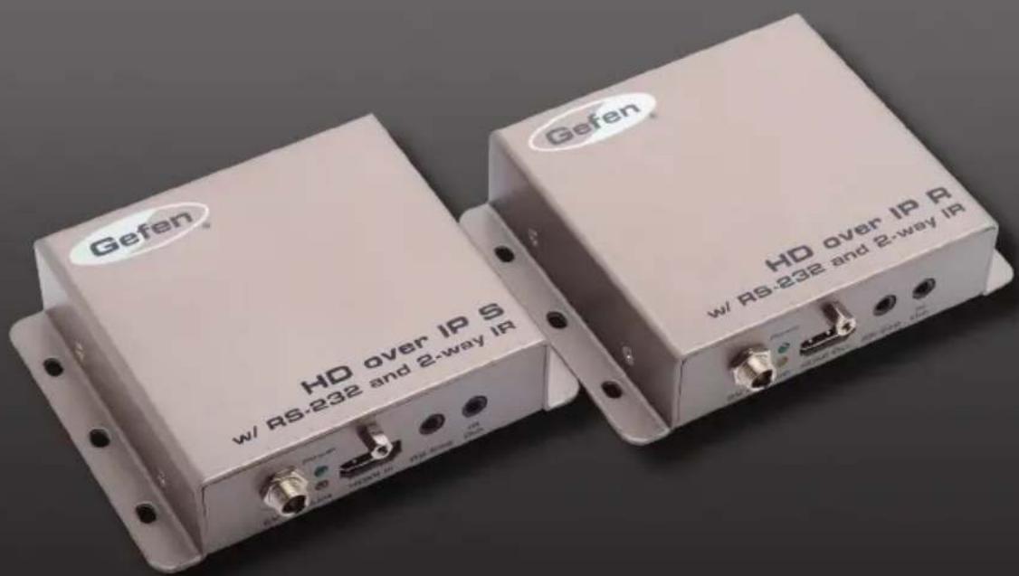
Gefen
HD over IP S w/ RS-232 and 2-way IR
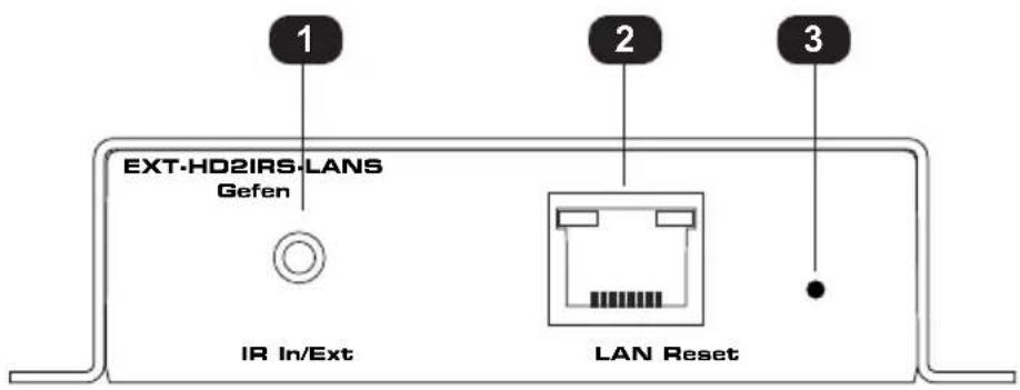
| ID Name Description | ||
| 1 IR In/Ext Connect an IR Extender (Gefen part no. | ||
| EXT-RMT-EXTIRN) to this port. Alternatively, connect a mini-mono 3.5mm cable from this port to the output of an automation system with an electrical IR output. | ||
| 2 LAN Connects the Sender unit to the network (or directly to the LAN port on the Receiver unit) using an Ethernet cable. | ||
| 3 Reset Press this button to reset the Sender unit. See Resetting a Unit (page 40) for instructions on restoring the Sender unit to factory-default settings. | ||
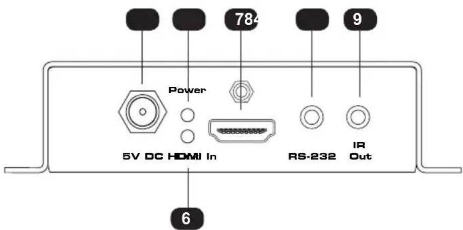
| 4 5V DC Connect the included 5V DC power supply to this locking power receptacle. | ||
| 5 Power This LED indicator will glow bright green and will remain illuminated as long as the power supply is connected to the Sender unit. | ||
| 6 Link This LED indicator will glow bright | amber to indicate that the Sender unit is communicating with the Receiver unit. If this LED is not illuminated, inspect the connection between the Sender and Receiver unit. | |
| 7 HDMI In Use the included HDMI cable to connect a Hi-Def source to this HDMI port. | ||
| 8 RS-232 Connect the included 3.5mm mini-stereo-to-DB-9 (female) adapter to this port. Connect an RS-232 cable from the adapter to an automation device. | ||
| 9 IR Out Connect the included infrared IR emitter (Gefen part no. EXT-IREMIT) from this port to the IR sensor window of the source. | ||
Receiver Unit
Gefen
HD over IP R w/ RS-232 and 2-way IR
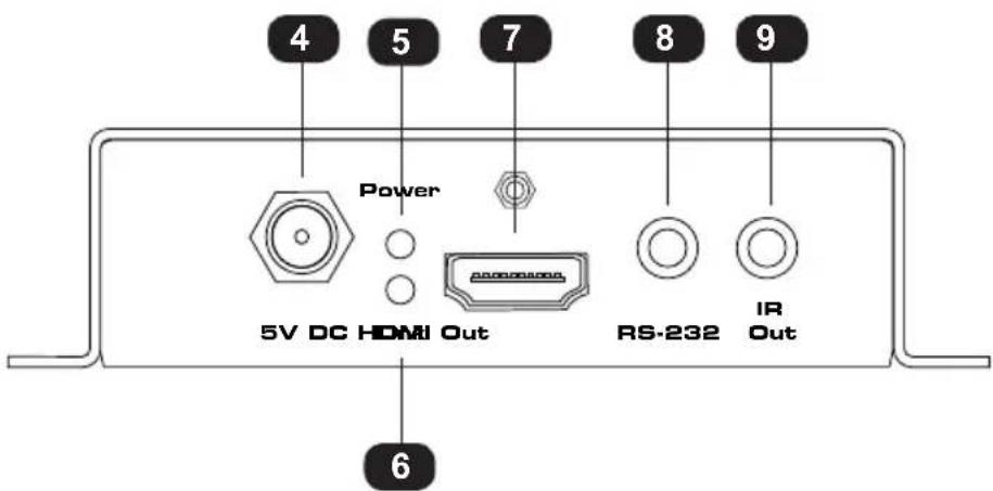
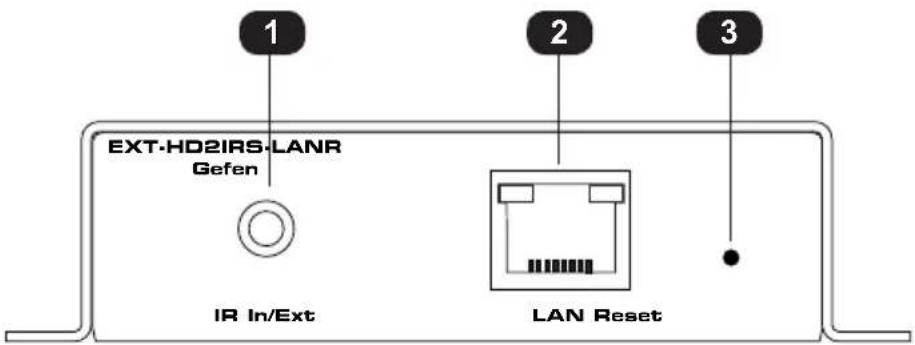
| ID Name Description | ||
| 1 IR In/Ext Connect the included IR Extender to this port. Alternatively, connect a mini-mono 3.5mm cable from this port to the output of an automation system with an electrical IR output. | ||
| 2 LAN Connects the Receiver unit to the network (or directly to the LAN port on the Sender unit) using an Ethernet cable. See the next page for installation instructions. | ||
| 3 Reset Press this button to reset the Receiver unit.See Performing a Factory Reset (page 5) for instructions on restoring the Receiver unit to factory-default settings. | ||
| 4 5V DC Connect the included 5V DC power supply to this locking power receptacle. | ||
| 5 Power This LED indicator will glow bright green and will remain illuminated as long as the power supply is connected to the Receiver unit. | ||
| 6 Link This LED indicator will glow bright amber to indicate that the Receiver unit is communicating with the Sender unit. If this LED is not illuminated, inspect the connection between the Sender and Receiver unit. | ||
| 7 HDMI Out Connect an HDMI cable between this ports and an HDTV display. | ||
| 8 RS-232 Connect the included 3.5mm mini-stereo-to-DB-9 (male) adapter to this port. Connect an RS-232 cable from the adapter to a display or other RS-232 device. | ||
| 9 IR Out Connect an infrared IR emitter (Gefen part no. EXT-IREMIT) from this port to the IR sensor window of the source. |
The HD over IP w/ RS-232 and 2-way IR Sender and Receiver units can either be connected over a Local Area Network (LAN) or they can be directly connected to one another.
Using a Direct Connection
By default, Sender and Receiver units are shipped in Auto IP mode. In Auto IP mode, each Sender and Receiver unit assigns itself a unique IP address within the range of 169.254.x.x. Auto IP mode is used only when Sender and Receiver units are directly connected to one another. When connecting to a network, the Sender and Receiver units must be set to either DHCP or Static IP mode. See Setting the IP Mode (page 22) for more information.
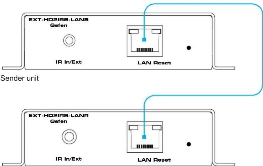
- Connect a CAT-5e (or better) cable from the LAN port on the Sender unit to the LAN port on the Receiver unit. The cable should not exceed 330 feet (100 meters) in length.
Figure 1.1 - Directly connecting the Sender and Receiver unit
Receiver unit
- Use the included HDMI cable to connect the Hi-Def source to the HDMI In port on the Sender unit.
- Connect an HDMI cable from the HDTV display to the HDMI Out port on the Receiver unit.
- See Additional Connections (page 8) to complete the installation process.
Local Area Network (LAN) Connection

Important!
This product requires a Gigabit switch that supports 8k jumbo frames in order for multicast mode to function correctly. If the LAN is not exclusively dedicated to this product, then a managed switch is highly recommended.
In order to connect the HD over IP w/ RS-232 and 2-way IR to a Local Area Network (LAN), both the Sender and Receiver unit must first be set to DHCP or static IP mode. DHCP mode will use the DHCP server to automatically assign an IP address for each Sender and Receiver unit that is connected to the network. Static IP mode will allow the IP address for each Sender and Receiver unit to be configured manually. Contact your network administrator if necessary.
- Connect an Ethernet cable from the LAN port on both the Sender and Receiver unit directly to the router. Each cable that is connected to the router should not exceed 330 feet (100 meters) in length.
- Access the Web interface for the Sender unit by entering its IP address in the address bar of the Web browser. If the IP address is not known, see Displaying the IP Address (page 7).
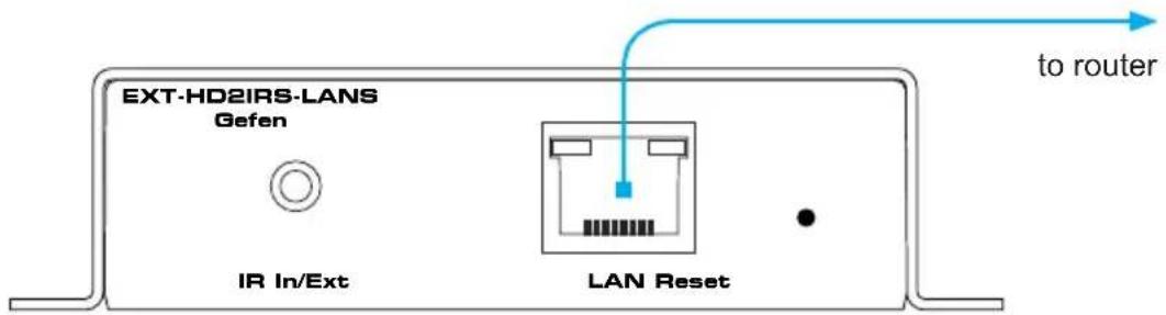
Sender unit
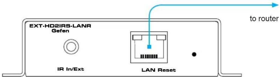
Receiver unit
(continued on next page)
- Set the desired network mode (DHCP or static). Refer to Setting the IP Address (page 24) for instructions on setting the network mode.
- Repeat steps 2 and 3 for the Receiver unit.
- Once the IP addresses have been assigned, disconnect the Sender and Receiver units from the router and connect them to the network.
- Follow steps 2 - 4, under Using a Direct Connection (page 6). to complete the installation process.
Additional Connections
▶ IR
- Refer to the section entitled Bidirectional IR Control (page 12) for details on connecting IR devices.
RS-232
-
Connect the mini-stereo-to-DB-9 (female) cable adapter from the RS-232 port on the Sender unit to a DB-9 cable. Connect the DB-9 cable to an automation system.
-
Connect the mini-stereo-to-DB-9 (male) cable adapter from the RS-232 port on the Receiver unit to a DB-9 cable. Connect the DB-9 cable to a display or other RS-232 device.
▶ Power
-
Connect the included 5V DC locking power supplies to the 5V DC receptacle on the Sender unit and Receiver unit. Do not overtighten the locking connectors.
-
Connect the included AC power cords from the power supplies to available electrical outlets.
Sample Wiring Diagram
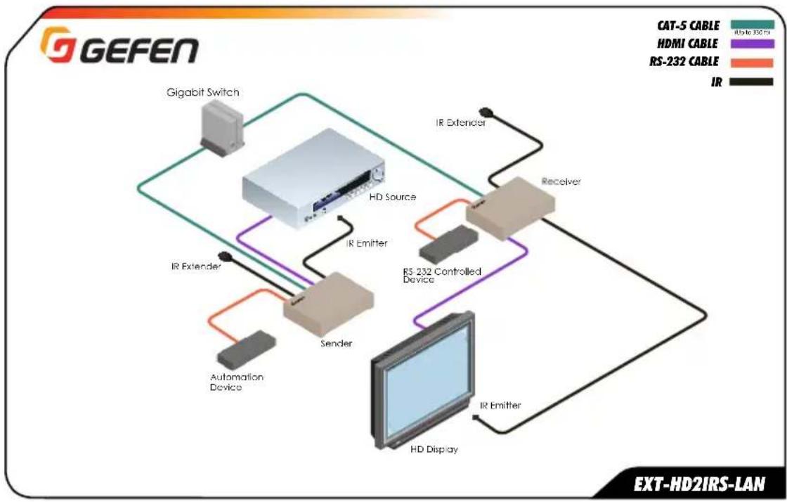
flowchart
graph TD
    A["Gigabit Switch"] --> B["HD Source"]
    C["IR Extender"] --> B
    D["Sender"] --> B
    E["HD Display"] --> B
    B --> F["Receiver"]
    F --> G["IR Extender"]
    G --> H["RS-232 Controlled Device"]
    H --> I["IR Emitter"]
    I --> J["HD Display"]
    K["Automation Device"] --> B
    L["IR Extender"] --> B
    M["RS-232 Cable"] --> N["IR"]
    O["HDMI Cable"] --> P["IR"]
    Q["RTS Cable"] --> R["IR"]
    S["RTS Cable"] --> T["IR"]
    U["RTS Cable"] --> V["IR"]
    W["RTS Cable"] --> X["IR"]
HD over IP
w/ RS-232 and 2-way IR
2 Basic Operation
Bidirectional IR Control.... 12
Controlling the Source from the Viewing Location 12
Controlling the Display from the Source Location 13
Controlling the Source / Display from Different Locations.... 14
Displaying the IP Address 15
Web Interface....16
Login Procedure....16
Viewing System Settings.... 18
Setting the Password 19
Setting the Video Channel 20
Setting the IP Mode....22
Setting the IP Address 24
Enabling or Disabling Video over IP 25
Enabling or Disabling HDCP 26
Picture Quality Mode 27
EDID Management....28
Using the Internal EDID 28
Using the Downstream EDID 29
Unicast and Multicast Modes 30
Configuring Unicast Mode.... 30
Switching between Sender units in Unicast mode 32
Configuring Multicast Mode.... 35
Using RS-232 37
RS-232 under Unicast Mode 39
RS-232 under Multicast Mode.... 39
Resetting a Unit....40
Controlling the Source from the Viewing Location
- Connect the included IR extender to the IR In/Ext port on the Receiver unit. If using an automation system, connect the 3.5mm mini-stereo connector from the IR In/Ext port on the Receiver unit to the automation system.
- Connect the included IR emitter from the IR Out port on the Sender unit to the IR sensor window on the source device.
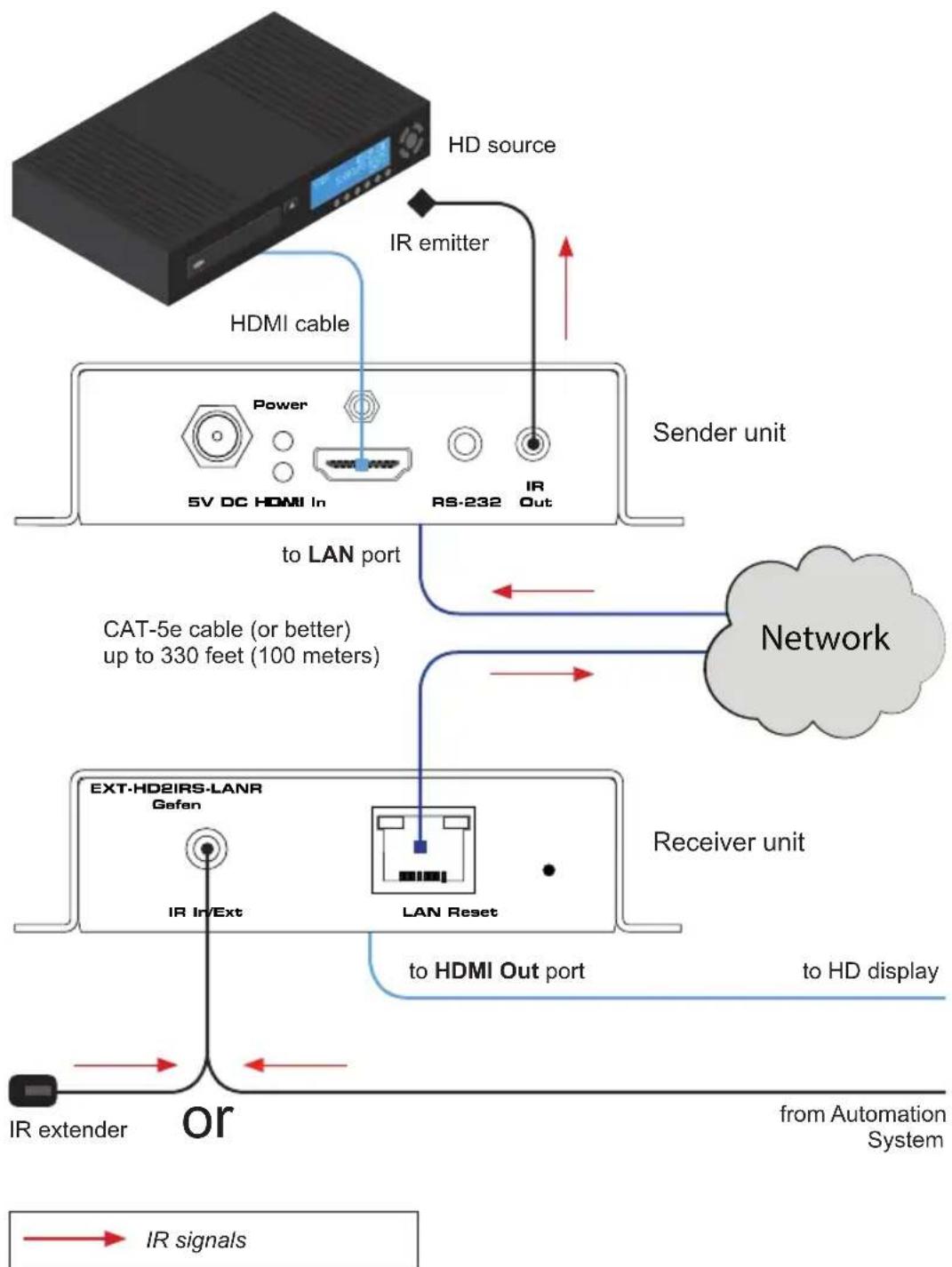
flowchart
graph TD
    A["HD source"] --> B["HDMI cable"]
    B --> C["5V DC HDMI In"]
    C --> D["RS-232"]
    D --> E["IR Out"]
    F["IR emitter"] --> B
    G["Network"] --> H["to LAN port"]
    H --> I["CAT-5e cable (or better) up to 330 feet (100 meters)"]
    I --> J["Receiver unit"]
    J --> K["LAN Reset"]
    K --> L["to HDMI Out port"]
    L --> M["to HD display"]
    N["IR extender"] --> O["or"]
    P["from Automation System"] --> Q["→ IR signals"]
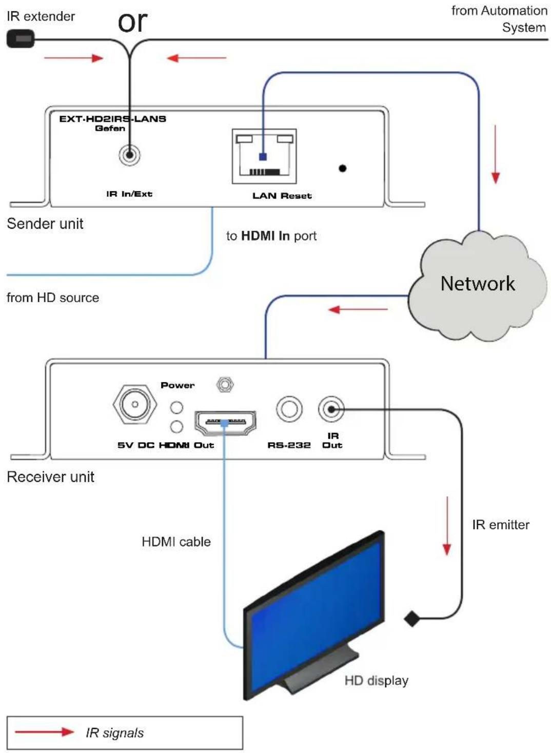
Controlling the Display from the Source Location
-
Connect an IR extender (Gefen part no. EXT-RMT-EXTIRN) to the IR In/Ext port on the Sender unit. If using an automation system, connect the 3.5mm mini-stereo connector from the IR In/Ext port on the Sender unit to the automation system.
-
Connect an IR emitter (Gefen part no. EXT-IREMIT) from the IR Out port on the Receiver unit to the IR sensor on the display.
flowchart
graph TD
    A["IR extender"] --> B["or"]
    B --> C["EXT-HD2IRS-LANS\nGefen"]
    B --> D["LAN Reset"]
    C --> E["from Automation System"]
    D --> F["to HDMI In port"]
    G["Network"] --> H["Receiver unit"]
    H --> I["HDMI cable"]
    I --> J["HD display"]
    K["IR emitter"] --> J
    L["IR signals"] --> J
    M["5V DC HDMI Out"] --> N["Power"]
    O["RS-232"] --> P["IR Out"]
    Q["Sender unit"] --> R["to HDMI In port"]
Controlling the Source / Display from Different Locations

Information
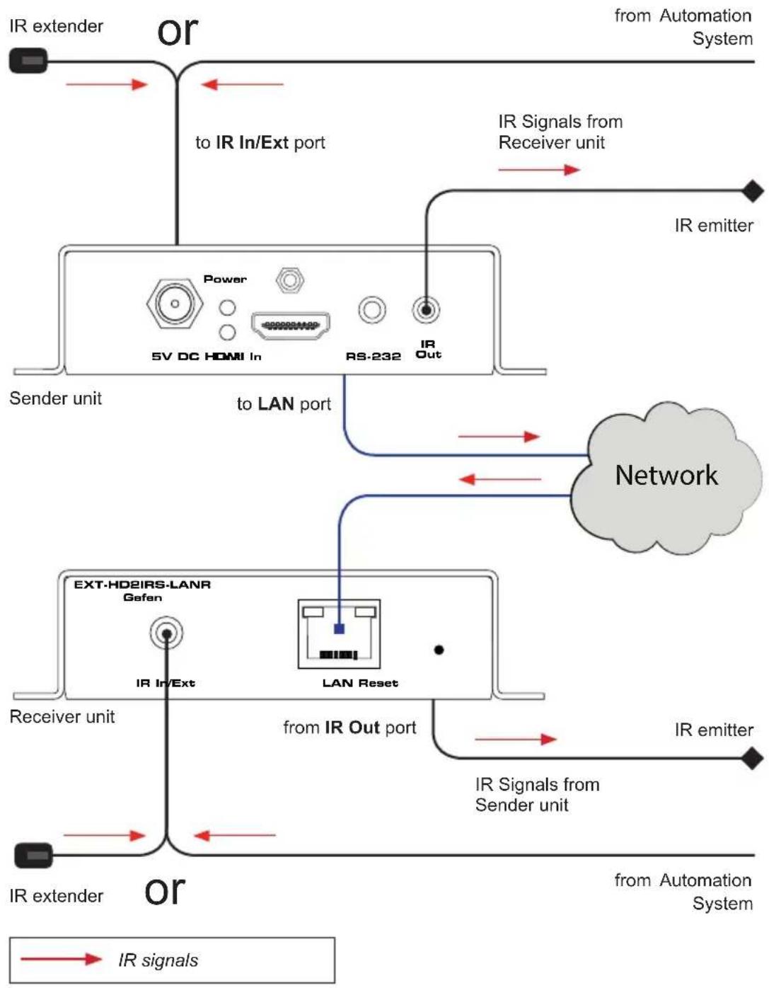
Additional IR extenders (Gefen part no. EXT-RMT-EXTIRN) and IR emitters (Gefen part no. RMT-2IREMIT) will be required for this configuration.
Using bidirectional IR, the HD over IP w/ RS-232 and 2-way IR allows the source and/or display to be controlled from the viewing location or the source location. Refer to the diagram, below, for connection details. The video cables have been removed for clarity.
flowchart
graph TD
    A["IR extender"] --> B["or"]
    B --> C["to IR In/Ext port"]
    C --> D["5V DC HDMI In"]
    D --> E["RS-232"]
    E --> F["IR Out"]
    F --> G["Network"]
    G --> H["IR emitter"]
    H --> I["from Automation System"]
    B --> J["to LAN port"]
    J --> K["Power"]
    K --> L["5V DC HDMI In"]
    L --> M["RS-232"]
    M --> N["IR Out"]
    N --> O["Network"]
    O --> P["from Automation System"]
    Q["EXT-HD2IRS-LANR Gafen"] --> R["IR Ir/Ext"]
    R --> S["LAN Reset"]
    S --> T["from IR Out port"]
    T --> U["IR emitter"]
    U --> V["from Automation System"]
    W["IR extender"] --> X["or"]
    X --> Y["to IR In/Ext port"]
    Y --> Z["5V DC HDMI In"]
    Z --> AA["RS-232"]
    AA --> AB["IR Out"]
    AB --> AC["Network"]
    AC --> AD["from Automation System"]
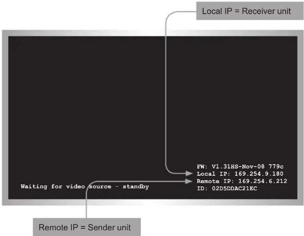
The IP addresses of both the Sender and Receiver unit are briefly displayed during the initialization process, before an image is displayed. To retrieve the IP address of a Sender and/or Receiver unit, at any time, use the following procedure.
- Disconnect the HDMI cable from the HDMI In port on the Sender unit. Do not disconnect the HDMI cable from the Receiver unit.
- After a few moments, the screen will go blank and the IP address of both the Sender and Receiver unit will be displayed in the lower-right corner of the screen.
flowchart
graph TD
    A["Local IP = Receiver unit"] --> B["Waiting for video source - standby"]
    B --> C["Remote IP = Sender unit"]
    C --> D["FW: V1.31HS-Nov-08 779c"]
    C --> E["Local IP: 169.254.9.180"]
    C --> F["Remote IP: 169.254.6.212"]
    C --> G["ID: 02D5DDAC21EC"]
- To display the source image, once again, reconnect the HDMI cable to the HDMI In port on the Sender unit.
Login Procedure
Each Sender and Receiver uses a built-in Web interface which is used to assign settings and control the features of each unit. The Web interface features a login screen which provides two access types: Administrator login provides access to all features and settings. Operator login limits access to channel switching and video modes.
- Access the Web interface by entering the IP address of the Sender or Receiver unit in the address bar of a Web browser. Refer to Displaying the IP Address (page 16) if necessary.
- The Login tab will be displayed in the Web interface.
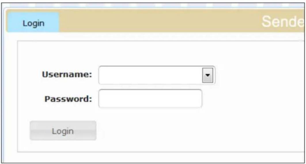
- Click the arrow next to the Username field.
- Two user names will be displayed: Administrator and User.
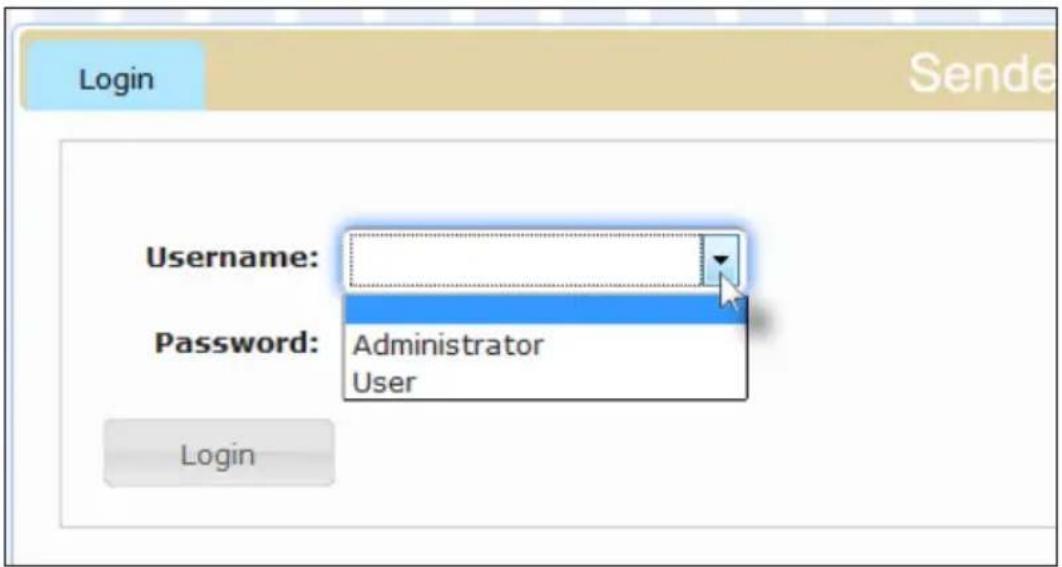
- For this example, select the User name.
- Enter the password in the Password field. By default, the password for the User login is user. The default password for the Administrator login is admin. Note that these passwords are case-sensitive.
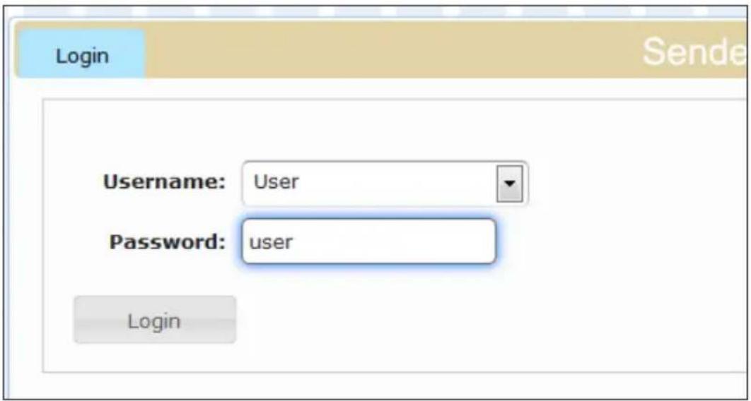
- Click the Login button.
- The Network tab will appear, just to the right of the Login tab.
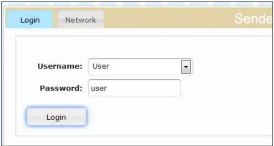
If the Administrator login is used, additional tabs will be displayed:

Viewing System Settings
The Login screen displays the current version of firmware, network mode, and IP addresses.
- Access the Web interface for the Sender or Receiver unit. The password must be set for each Sender and Receiver unit.
- The Login tab will be highlighted.
- Locate the Firmware version and System settings sections, as shown below.
Firmware version
kernel version: A5.11 webfwh version: V1.35hs
System settings
Network Mode: Unicast Mode
IP Mode: autoip
IP Address: 169.254.6.204
Subnet Mask: 255.255.0.0
Default Gateway: 169.254.0.254

Information
The firmware version can also be found under the System tab, when logging in as Administrator.
Setting the Password
Both the User and Administrator passwords can be changed. Each Sender and Receiver unit can have a different password, if desired. To prevent unauthorized tampering of configuration settings, it is highly recommended that the Administrator password be changed as soon as each unit is configured. Passwords are case-sensitive.
The default password for Administrator is admin. The default password for User is user.
- Access the Web interface for the Sender and Receiver unit. The password must be set for each Sender and Receiver unit.
- Log in as Administrator.
- Click the System tab.
- Enter the new password for the desired user name(s). In the example, below, both the Administrator and User passwords are being changed.
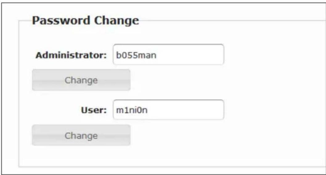
- Click the Change button under the appropriate user name.
- The following message will be displayed, at the top of the page:

Success: New Password applied.
- Return to the Login tab and login as with the new password. This step will terminate the current session (using the old password), allowing the new password to take effect.
Setting the Video Channel
In order for Sender and Receiver units to communicate with one another, they must both be set to the same video channel. This is similar to changing the channel on a cable or satellite box in order to view a different program. By default, all Sender and Receiver units are set to channel 0.

Information
When connecting Sender and Receiver units, it is highly recommend that the video channel for each unit is set to a channel other than 0. This will allow for the addition of future Sender and/or Receiver units without causing video channel conflicts.
- Access the Web interface by entering the IP address of the desired Sender or Receiver unit in the address bar of a Web browser. Refer to Displaying the IP Address (page 20) if necessary.
- Log in as Administrator or User.
- Click the Network tab. The current channel is displayed within the Network Mode window group.
- Click the Channel Selection drop-down list and select the desired channel. Channel numbers can range from 0 to 255.
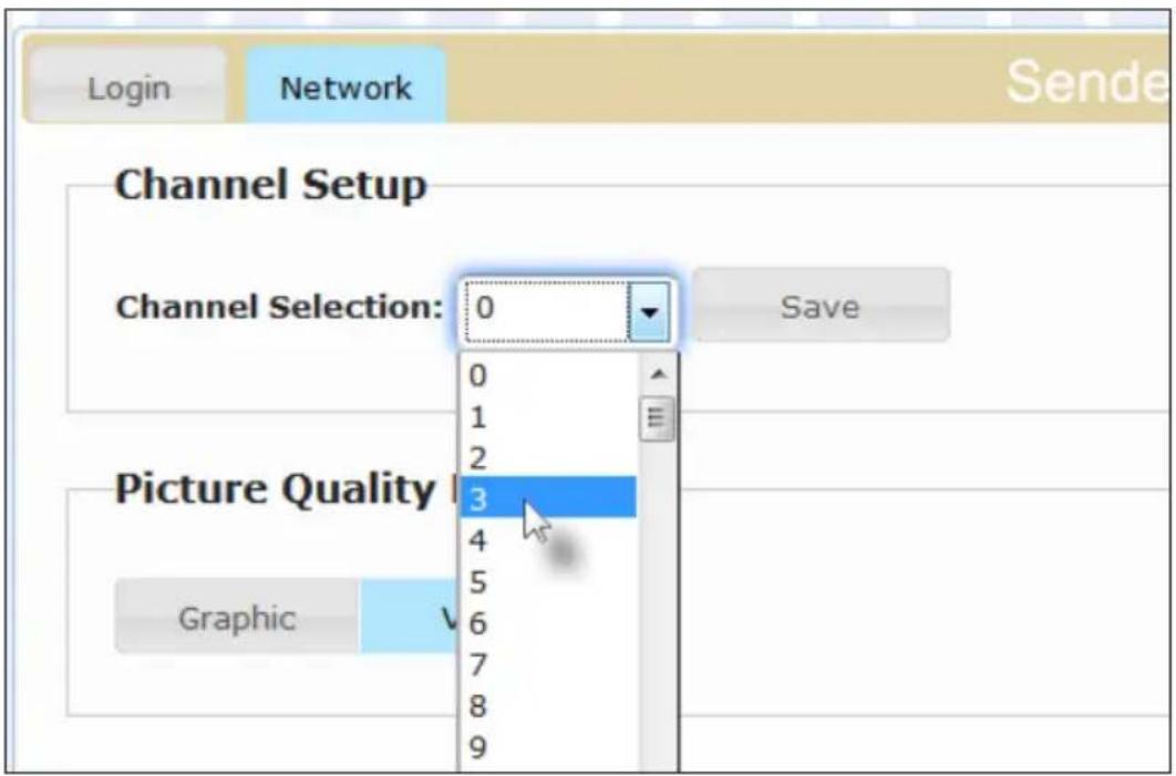
- Click the Save button on the right-hand side of Network Mode window group.
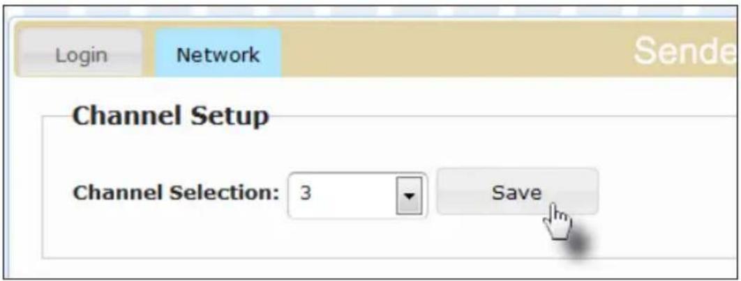
- The following message will be displayed, at the top of the page, indicating that the casting mode has been applied to the Sender or Receiver unit.
i Success: New casting mode applied.
- Repeat steps 1 - 5 for each Sender and Receiver to be changed.
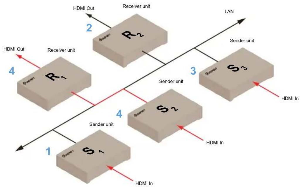
For example, in Figure 2.1, let's say we are currently connected to the Web interface of Receiver unit R1. The numbers in blue represent the video channel that has been assigned to each Sender and Receiver unit. Receiver unit R1 is set to video channel 4. Sender unit S2 is also set to video channel 4. Therefore, we are only able to view the source that is connected to Sender unit S2.
If we wanted to view the source that is connected to Sender unit S3, then we would change Receiver unit R1 from channel 4 to channel 3.
Figure 2.1 - Switching between Sender units (sources).
flowchart
graph TD
    A["1"] --> B["S1"]
    B --> C["2"]
    C --> D["R2"]
    D --> E["3"]
    E --> F["S3"]
    F --> G["4"]
    G --> H["R1"]
    H --> I["5"]
    I --> J["6"]
    J --> K["R2 Out"]
    K --> L["LAN"]
    style A fill:#f9f,stroke:#333
    style B fill:#f9f,stroke:#333
    style C fill:#f9f,stroke:#333
    style D fill:#f9f,stroke:#333
    style E fill:#f9f,stroke:#333
    style F fill:#f9f,stroke:#333
    style G fill:#f9f,stroke:#333
    style H fill:#f9f,stroke:#333
    style I fill:#f9f,stroke:#333
    style J fill:#f9f,stroke:#333
    style K fill:#f9f,stroke:#333
    style L fill:#f9f,stroke:#333
    style_M["Sender unit"] --> N["6"]
    M --> O["7"]
    P["HDMI In"] --> Q["8"]
    R["HDMI Out"] --> S["9"]
Setting the IP Mode
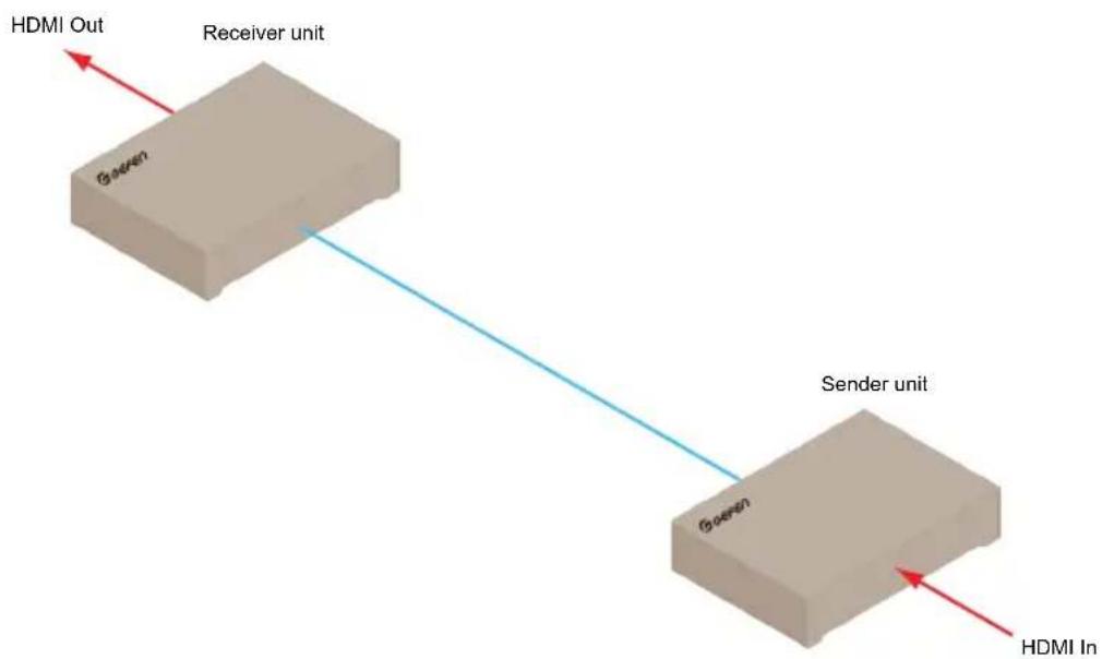
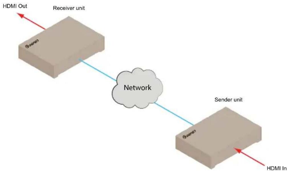
The HD over IP w/ RS-232 and 2-way IR can be set to Auto IP, DHCP, or Static IP mode. By default, Sender and Receiver units are shipped in Auto IP mode. Auto IP mode is used to directly connect a Sender and Receiver unit. In order to use the Sender and Receiver units in a LAN environment, they must be set to either DHCP or Static IP mode.
Figure 2.2 - Auto IP mode: A Sender and Receiver directly connected to one another.
flowchart
graph LR
    A["HDMI In"] --> B["Sender unit"]
    B --> C["Receiver unit"]
    C --> D["HDMI Out"]
    style A fill:#f9f,stroke:#333
    style B fill:#ccf,stroke:#333
    style C fill:#cfc,stroke:#333
    style D fill:#fcc,stroke:#333
Figure 2.3 - DHCP or Static IP mode: A Sender and Receiver unit connected to a network (LAN).
flowchart
graph LR
    A["Receiver unit"] -->|HDMI Out| B["Green"]
    B --> C["Network"]
    C -->|HDMI In| D["Sender unit"]
    D -->|Green| C
- Access the Web interface by entering the IP address of the Sender unit in the address bar of a Web browser. Refer to Displaying the IP Address (page 23), if necessary.
- Log in as Administrator.
- Click the Network tab. The current IP Mode will be highlighted within the IP Setup window group. In the illustration below, the (default) Auto IP button is highlighted.
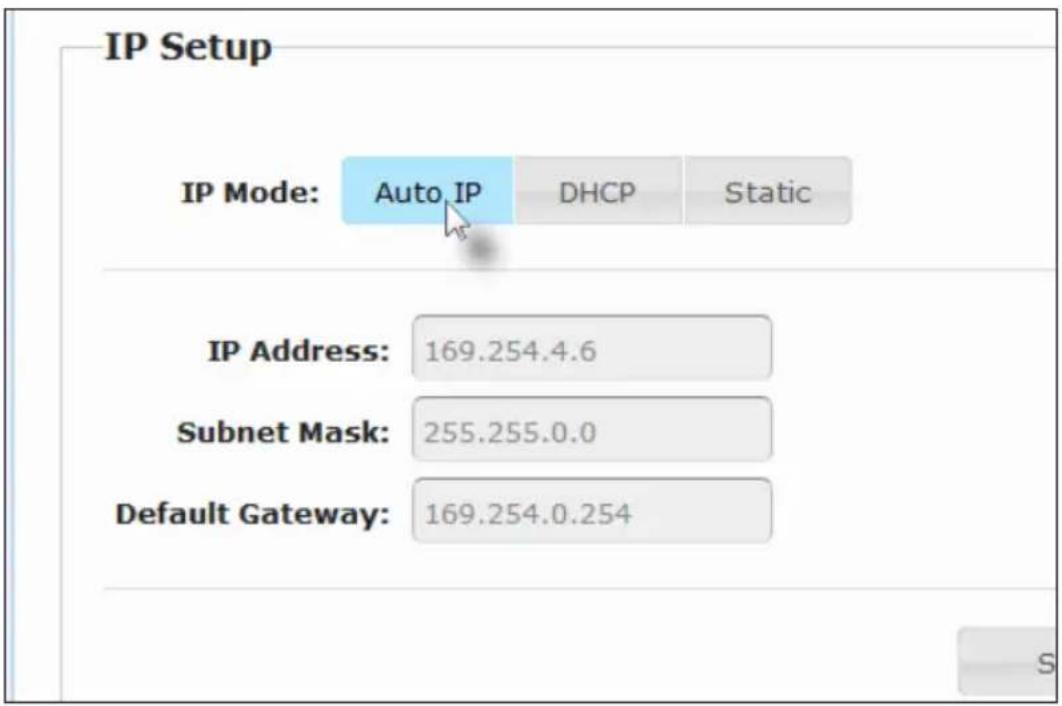
- Click the desired IP Mode button. The selected IP Mode button will turn blue.
If DHCP is selected, a DHCP server will automatically assign an IP address to each Sender and Receiver unit.
If Static is selected, the IP Address, Subnet Mask, and Default Gateway fields must entered manually. Refer to Setting the IP Address (page 24).
- Click the Save button on the right-hand side of IP Setup window group.
- Click the Reboot button near the bottom of the page.
- Repeat steps 2 - 5 for each Sender and Receiver to be changed.
Setting the IP Address
The HD over IP w/ RS-232 and 2-way IR can be set to Auto IP, DHCP, or Static IP mode. By default, the Sender and Receiver units are shipped in Auto IP mode. In order to use a specific IP address, the desired Sender and/or Receiver units must be placed in Static IP mode. See Setting the IP Mode (page 22). Contact the system administrator to obtain available IP addresses.
- Access the Web interface by entering the IP address of the Sender unit in the address bar of a Web browser. Refer to Displaying the IP Address (page 24), if necessary.
- Log in as Administrator.
- Click the Network tab. The current IP Mode will be highlighted within the IP Setup window group.
- Click the Static button.
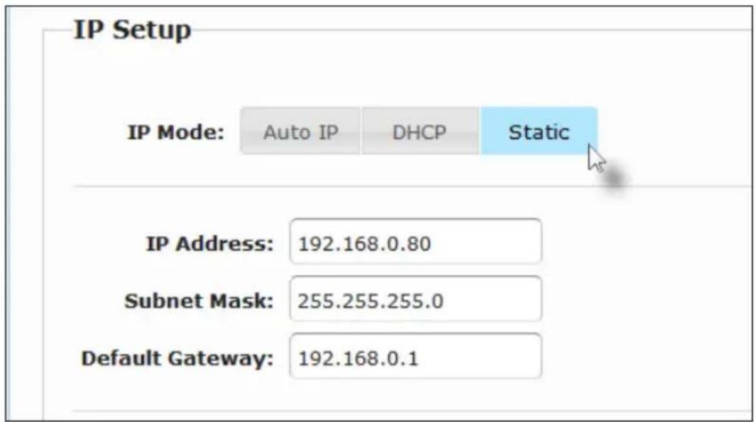
- Enter the IP address, subnet mask, and default gateway for this unit.
- Click the Save button on the right-hand side of IP Setup window group.
- Repeat steps 1 - 6 for each Sender and Receiver to be changed.
Enabling or Disabling Video over IP
This feature is useful for masking video. Disabling the video on the Sender unit will mask the video on all connected Receiver units (multicast mode only). To mask the video on selected Receiver units, disable the video on the desired Receiver units. By default, the Video over IP option is enabled.
- Access the Web interface by entering the IP address of the Sender or Receiver unit in a Web browser. Refer to Displaying the IP Address (page 25), if necessary.
- Log in as Administrator.
- Click the Functions tab.
- By default, the Video over IP option is enabled. Click the Enable Video over IP check box to remove the check mark and mask the video. Click the check box again to add the check mark and enable the video.
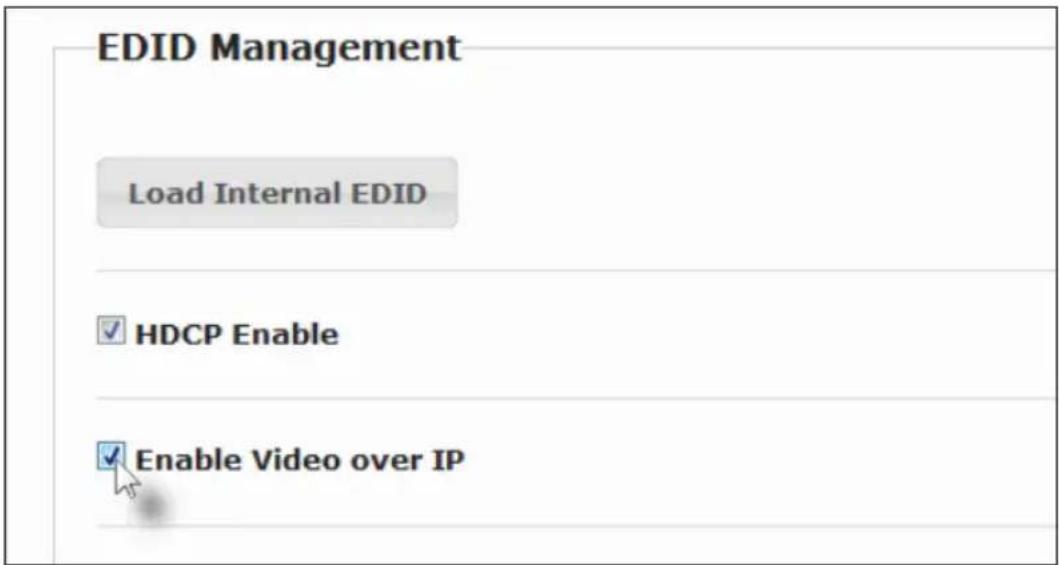
- Click the Save button within the Video over IP group.
- Click the Reboot button at the bottom of the page.
- Repeat steps 1 through 5 for each Sender and/or Receiver unit in the system.
Enabling or Disabling HDCP
As a rule, an HDCP-compliant display must be used when displaying HDCP content from a source device (e.g. Blu-ray). However, there may be instances where we simply want to view the desktop of a computer. Normally, this isn't a problem. Yet, some computers will always transmit HDCP even though HDCP is not required. Disabling this feature will force the computer to not transmit HDCP.
- Access the Web interface by entering the IP address of the Sender unit in a Web browser. Refer to Displaying the IP Address (page 26), if necessary.
- Log in as Administrator.
- Click the Functions tab.
- By default, the HDCP content is passed through. To disable HDCP content from being passed, click the HDCP Enable check box to remove the check mark. Click the check box again to add the check mark and allow HDCP content to be passed.
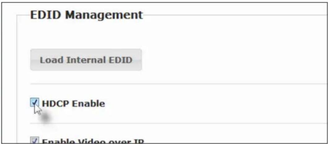
- Click the Save button within the Video over IP group.
- Click the Reboot button at the bottom of the page.
- Repeat steps 1 through 5 for each Sender and/or Receiver unit in the system.
Picture Quality Mode
The HD over IP w/ RS-232 and 2-way IR provides two video modes: Video Mode and Graphic Mode. If the input signal is motion video, then use the Video Mode setting. This will optimize the frame rate. If the input signal is a static image, then use the Graphic Mode setting.
- Access the Web interface for the Sender unit.
- Log in as Administrator or User.
- Click the Network tab.
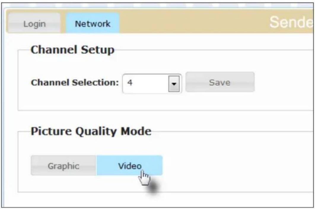
- Click the desired video mode button under the Picture Quality Mode window group. The select button will turn blue.
- The following message will be displayed, at the top of the page:
The HD over IP w/ RS-232 and 2-way IR features EDID Management. Before the source can send video (and/or audio) data, the source device (connected to each Sender unit) reads the EDID (Extended Display Identification Data) from the displays which are connected to each Receiver unit. The EDID contains information about what type of audio/video data can be sent by each source.
By default, the (downstream) EDID from the display, connected to the Receiver unit, is used. However, under certain circumstances, it may be desirable to use the internal EDID which is stored in the Sender unit.
Using the Internal EDID
- Access the Web interface for the Sender unit.
- Login as Administrator.
- Click the Functions tab.
- Click the Load Internal EDID button.
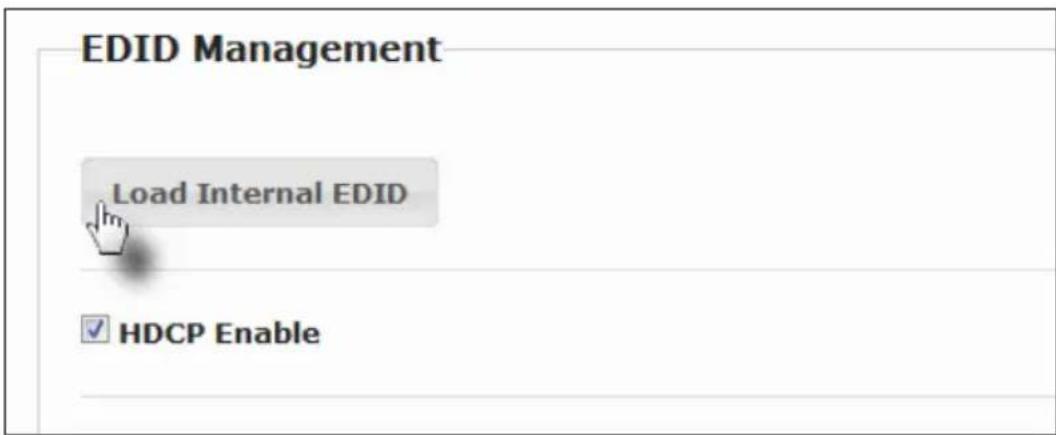
- After a few moments, the following message will appear at the top of the page, indicating that the new Serial over IP options have been applied.

Success: New video mode applied.
Clicking the Save or Reboot button is not required for the changes to take effect.
Using the Downstream EDID
By default, the (downstream) EDID from the display, connected to the Receiver unit, is used. If the internal EDID is being used (see previous page), then use the following procedure to use the downstream EDID.
-
Access the Web interface for the Receiver unit.
-
Login as Administrator.
-
Click the Functions tab.
-
Make sure that the Copy EDID of Connected Display box is checked. This is the default setting. Click this box if it is not checked then click the Save button.
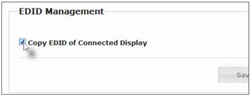

Warning!
Clicking the Load Internal EDID button, under the Sender unit, will override the status of the Copy EDID of Connected Display check box.
-
Click the Save button within the Video over IP group.
-
The following message will be displayed, at the top of the page:

Success: New video mode applied.
- After a few moments, the following message will be displayed:

Warning: Reboot for new settings to take effect.
-
Click the Reboot button at the bottom of the page.
-
The Sender unit will now use the EDID of the downstream sink device.
Configuring Unicast Mode
The term unicast is used to describe a configuration where information is sent from one point to another point. It is possible to have multiple Sender and Receiver units connected in a system. However, in unicast mode a Sender unit can communicate with only one Receiver unit at a time. In unicast mode, the HD over IP w/ RS-232 and 2-way IR functions similar to an HDMI switcher.

Information
The Sender and Receiver units are shipped from the factory in unicast mode.
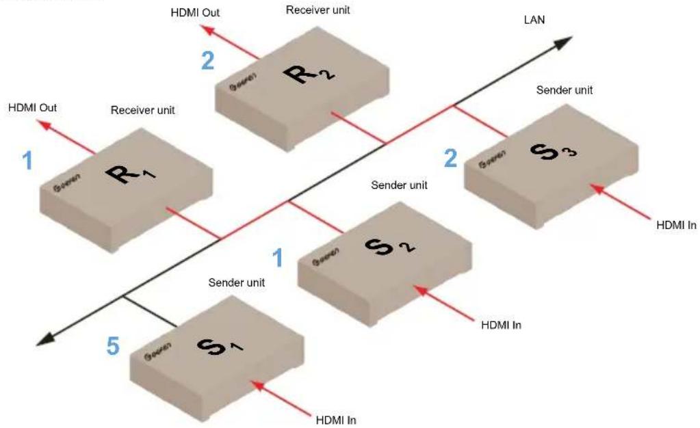
The illustration, below, shows 3 Sender units (S1, S2, and S3) and 2 Receiver units (R1 and R2) on a network, operating in unicast mode. The video channels are notated in blue. The red lines represent the video signal.
Figure 2.4 - Unicast mode: A Sender unit can communicate with only one Receiver unit at a time.
flowchart
graph TD
    A["Green"] -->|1| B["R1"]
    C["Green"] -->|5| D["S1"]
    E["Green"] -->|2| F["R2"]
    G["Green"] -->|2| H["S3"]
    I["Green"] -->|1| J["Sender unit"]
    K["Green"] -->|1| L["Sender unit"]
    M["Green"] -->|1| N["Sender unit"]
    O["Green"] -->|1| P["Sender unit"]
    Q["Green"] -->|1| R["Sender unit"]
    S["Green"] -->|1| T["Sender unit"]
    U["Green"] -->|1| V["Sender unit"]
    W["Green"] -->|1| X["Sender unit"]
    Y["Green"] -->|1| Z["Sender unit"]
    AA["Green"] -->|1| AB["Sender unit"]
    AC["Green"] -->|1| AD["Sender unit"]
    AE["Green"] -->|1| AF["Sender unit"]
    AG["Green"] -->|1| AH["Sender unit"]
    AI["Green"] -->|1| AJ["Sender unit"]
    AK["Green"] -->|1| AL["Sender unit"]
    AM["Green"] -->|1| AN["Sender unit"]
    AO["Green"] -->|1| AP["Sender unit"]
    AQ["Green"] -->|1| AR["Sender unit"]
    AS["Green"] -->|1| AT["Sender unit"]
    AU["Green"] -->|1| AV["Sender unit"]
    AW["Green"] -->|1| AX["Sender unit"]
    AY["HDMI Out"] --> AZ["R2"]
    BA["HDMI In"] --> BB["S3"]
    BC["HDMI In"] --> BD["S2"]
    BE["HDMI In"] --> BF["S1"]
    BG["HDMI In"] --> BH["S0"]
    BI["HDMI In"] --> BJ["S2"]
    BK["HDMI In"] --> BL["S3"]
    BM["HDMI In"] --> BN["S2"]
    BO["HDMI In"] --> BP["S1"]
    BZ["HDMI Out"] --> CA["R1"]
    CB["HDMI In"] --> CC["S1"]
    CD["HDMI In"] --> DD["S2"]
    DJ["HDMI Out"] --> DK["R2"]
    DL["HDMI In"] --> DH["S3"]
    DI["HDMI In"] --> DJ["S2"]
    DK["HDMI Out"] --> DK
    EE["HDMI In"] --> EE["S1"]
    EE["HDMI In"] --> EE
    FF["HDMI Out"] --> GG["R1"]
    GH["HDMI In"] --> GG
    ID["HDMI Out"] --> IE["R2"]
    IJ["HDMI In"] --> IE
- Access the Web interface by entering the IP address of the Sender or Receiver unit in a Web browser. Refer to Displaying the IP Address (page 30), if necessary. In this example, we will start with Receiver unit R1.
- Log in as Administrator.
- Click the Network tab.

Tip
In unicast mode, the HD over IP w/ RS-232 and 2-way IR functions as a Switcher.
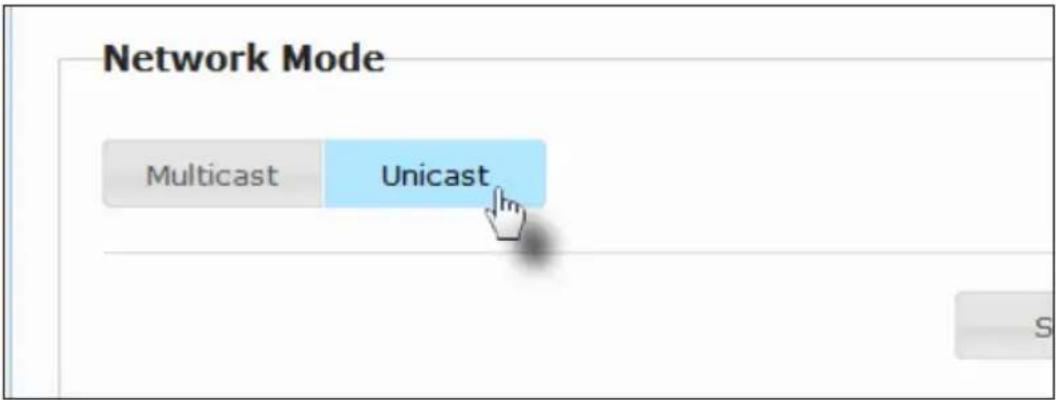
- Click the Unicast button under the Network Mode window group. When selected, the Unicast button will be highlighted in blue.
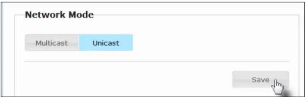
- Click the Save button in the lower-right corner of the Network Mode window group.
- The following message will be displayed, at the top of the page, indicating that the casting mode has been applied to the Sender or Receiver unit.

Success: New casting mode applied.
- After a few seconds, the following message will appear at the top of the screen:

Warning: Reboot for new settings to take effect.
- Click the Reboot button near the bottom portion of the page to apply the changes.
- Repeat steps 1 - 7 to configure each Sender and Receiver unit to unicast mode.

Important!
When switching between unicast and multicast modes, both Sender and Receiver units need to be configured identically.
Switching between Sender units in Unicast mode
When multiple Sender and Receiver unit are used in unicast mode, the HD over IP w/ RS-232 and 2-way IR behaves as a switcher. In unicast mode, a Sender unit can communicate with only one Receiver unit at a time.
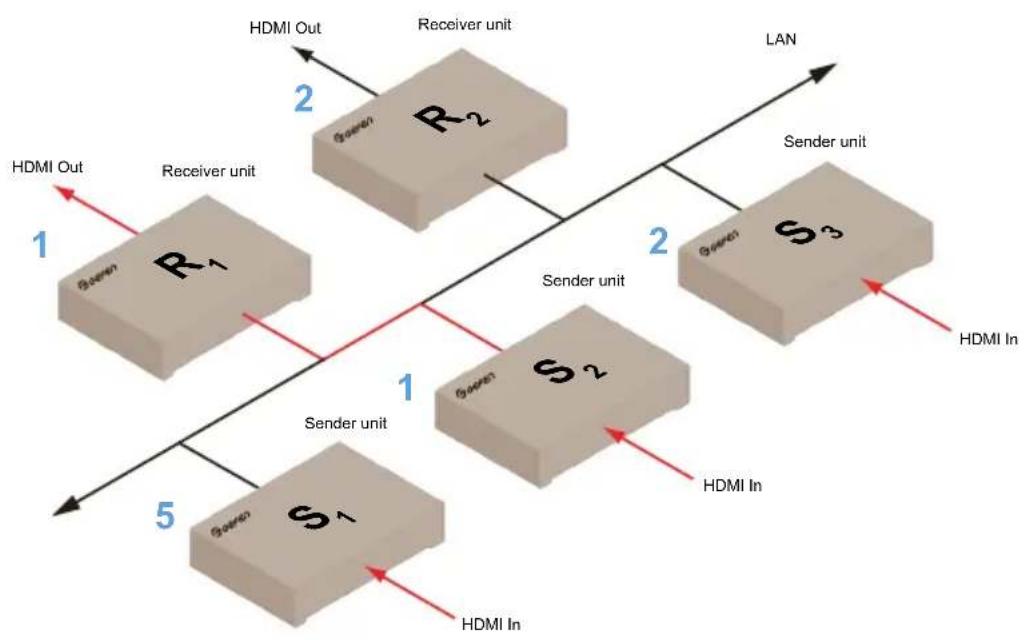
In the example below, we will switch Receiver unit R1 to receive the source on Sender unit S1.
Figure 2.5 - Unicast mode: Sender S2 transmitting to Receiver unit R1.
flowchart
graph TD
    A["1"] --> B["R1"]
    B --> C["2"]
    C --> D["Receiver unit"]
    D --> E["R2"]
    E --> F["2"]
    F --> G["Sender unit"]
    G --> H["S3"]
    H --> I["2"]
    I --> J["Sender unit"]
    J --> K["S2"]
    K --> L["1"]
    L --> M["Sender unit"]
    M --> N["S1"]
    N --> O["5"]
    O --> P["HDMI In"]
    Q["HDMI Out"] --> B
    R["HDMI In"] --> M
    S["HDMI Out"] --> B
    T["HDMI In"] --> M
- Access the Web interface for Receiver unit R1.
- Login as Administrator or User.
- Click the Network tab and change the video channel. Refer to Setting the Video Channel if necessary.
- Click the Save button.
- The following message will be displayed, at the top of the page, indicating that the casting mode has been applied to the Sender or Receiver unit.
i Success: New casting mode applied.
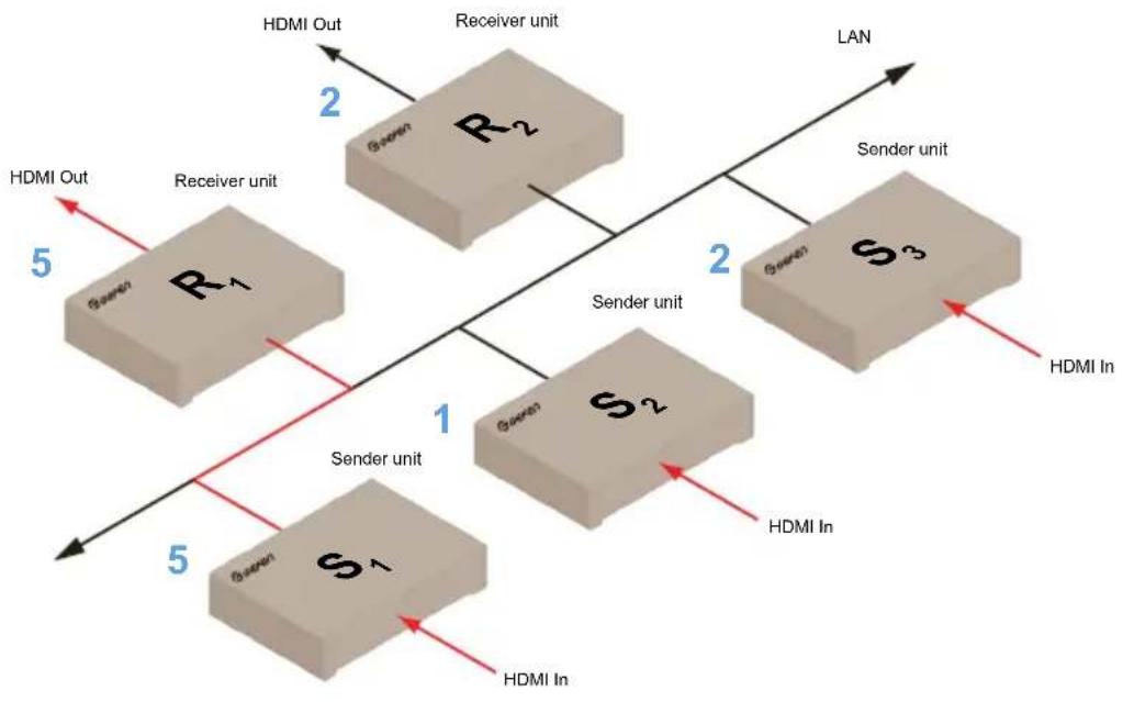
- Receiver unit R1 is now receiving the source on Sender unit S1, as shown on the next page.
Figure 2.6 - Unicast mode: Sender unit S1 transmitting to Receiver unit R1
flowchart
graph TD
    A["Sender unit"] --> B["R1"]
    A --> C["S1"]
    A --> D["S2"]
    A --> E["S3"]
    F["Sender unit"] --> G["R2"]
    F --> H["S2"]
    F --> I["S3"]
    J["HDMI Out"] --> K["Receiver unit"]
    L["HDMI In"] --> M["Sender unit"]
    N["HDMI Out"] --> O["Receiver unit"]
    P["HDMI In"] --> Q["Sender unit"]
    R["HDMI Out"] --> S["Receiver unit"]
    T["HDMI In"] --> U["Sender unit"]
    V["HDMI Out"] --> W["Receiver unit"]
    X["HDMI In"] --> Y["Sender unit"]
    Z["HDMI Out"] --> AA["Receiver unit"]
    AB["HDMI In"] --> AC["Sender unit"]
    AD["HDMI Out"] --> AE["Receiver unit"]
    AF["HDMI In"] --> AG["Sender unit"]
    AH["HDMI Out"] --> AI["Receiver unit"]
    AJ["HDMI In"] --> AK["Sender unit"]
    AL["HDMI Out"] --> AM["Receiver unit"]
    AN["HDMI In"] --> AO["Sender unit"]
    AP["HDMI Out"] --> AQ["Receiver unit"]
    AR["HDMI In"] --> AS["Sender unit"]
    AT["HDMI Out"] --> AU["Receiver unit"]
    AV["HDMI In"] --> AW["Sender unit"]
    AX["HDMI Out"] --> AY["Receiver unit"]
    AZ["HDMI In"] --> BA["Sender unit"]
    BB["HDMI Out"] --> BC["Receiver unit"]
    BD["HDMI In"] --> BE["Sender unit"]
    BF["HDMI Out"] --> BG["Receiver unit"]
    BH["HDMI In"] --> BI["Sender unit"]
    BJ["HDMI Out"] --> BK["Receiver unit"]
    BL["HDMI In"] --> BL["Sender unit"]
    BM["HDMI Out"] --> BN["Receiver unit"]
    BO["HDMI In"] --> BP["Sender unit"]
    BQ["HDMI Out"] --> BR["Receiver unit"]
    BS["HDMI In"] --> BT["Sender unit"]
    BU["HDMI Out"] --> BV["Receiver unit"]
    BW["HDMI In"] --> BX["Sender unit"]
    BY["HDMI Out"] --> BZ["Receiver unit"]
    CA["HDMI In"] --> CB["Sender unit"]
    CC["HDMI Out"] --> CD["Receiver unit"]
    CE["HDMI In"] --> CF["Sender unit"]
    DG["HDMI Out"] --> DH["Receiver unit"]
    DI["HDMI In"] --> DJ["Sender unit"]
    DK["HDMI Out"] --> DL["Receiver unit"]
    DM["HDMI In"] --> DJ
    DN["HDMI Out"] --> DO
    DO --> DO
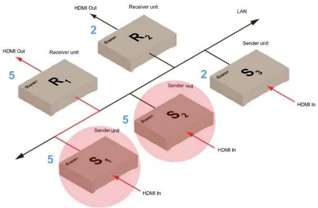
Note that each of the Sender units in Figure 2.6 is assigned a unique channel number. However, if we were to change the video channel on Sender unit S2 to channel 5, this would violate the unicast mode rule: A Sender unit can communicate with only one Receiver unit at a time.
Figure 2.7 - Unicast mode violation: Two Sender units (S1 and S2) using the same video channel.
flowchart
graph TD
    A["Sender unit"] --> B["Green"]
    B --> C["R1"]
    C --> D["HDMI Out"]
    D --> E["Receiver unit"]
    E --> F["R2"]
    F --> G["S2"]
    G --> H["Sender unit"]
    H --> I["S3"]
    I --> J["HDMI In"]
    J --> K["HDMI In"]
    style A fill:#f9f,stroke:#333
    style B fill:#ccf,stroke:#333
    style C fill:#cfc,stroke:#333
    style D fill:#fcc,stroke:#333
    style E fill:#cff,stroke:#333
    style F fill:#ffc,stroke:#333
    style G fill:#cfc,stroke:#333
    style H fill:#fcc,stroke:#333
    style I fill:#ffc,stroke:#333
    style J fill:#fcc,stroke:#333
    style K fill:#ffc,stroke:#333
In order to solve the problem, in Figure 2.7, we would need to make sure that each of the Sender units is set to a unique channel number.
When using unicast mode, each of the Sender units must be assigned a unique channel and should never be changed. Use the Receiver unit to switch (channels) between Sender units.
The HD over IP w/ RS-232 and 2-way IR can be used with just over 65,000 Sender and Receiver units, depending upon the network bandwidth and the number of ports on your network switch.

Information
In unicast mode, if an additional Sender unit is introduced into a system with the same channel as another Sender unit, then the Receiver unit will continue to receive A/V data from the Sender unit which was connected first.
Configuring Multicast Mode
The term multicast is used to describe a configuration where information is sent from one or more points to a set of other points. For example, a single Sender unit can transmit data to multiple Receiver units. In addition, if multiple Sender units are used, each Sender unit can transmit data to any Receiver that is not already receiving data from another Sender unit. In multicast mode, the HD over IP w/ RS-232 and 2-way IR functions similar to an HDMI matrix.
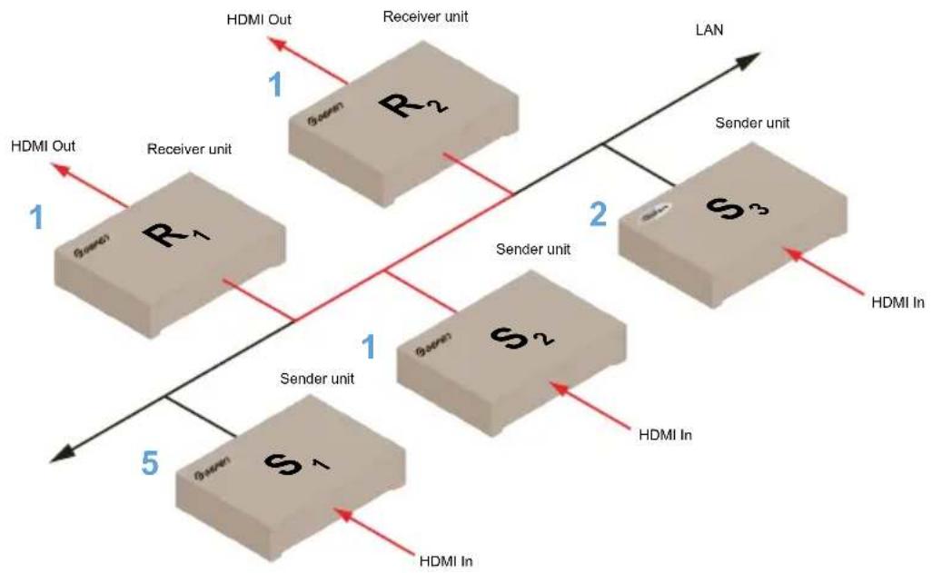
The following illustration shows three Sender units (S1, S2, and S3) and two Receiver units (R1 and R2) on a network, operating in multicast mode. Sender unit S2 is transmitting the video signal to Receiver units R1 and R2. The video channels are shown in blue. The video signals are shown in red.
Figure 2.8 - Multicast mode: A Sender unit can communicate with multiple Receiver units.
flowchart
graph TD
    A["1"] --> B["R1"]
    B --> C["2"]
    C --> D["S3"]
    D --> E["5"]
    E --> F["S1"]
    F --> G["1"]
    G --> H["Sender unit"]
    H --> I["HDMI In"]
    H --> J["HDMI In Out"]
    K["1"] --> L["2"]
    L --> M["Sender unit"]
    M --> N["HDMI In"]
    M --> O["HDMI In Out"]
    P["1"] --> Q["5"]
    Q --> R["HDMI In"]
    Q --> S["HDMI In Out"]
    T["1"] --> U["2"]
    U --> V["Sender unit"]
    V --> W["HDMI In"]
    V --> X["HDMI In Out"]
    Y["1"] --> Z["2"]
    Z --> AA["Sender unit"]
    AA --> AB["HDMI In"]
    AA --> AC["HDMI In Out"]
    AD["1"] --> AE["2"]
    AE --> AF["Sender unit"]
    AF --> AG["HDMI In"]
    AF --> AH["HDMI In Out"]
    AI["1"] --> AJ["2"]
    AJ --> AK["Sender unit"]
    AK --> AL["HDMI In"]
    AK --> AM["HDMI In Out"]
    AN["1"] --> AO["2"]
    AO --> AP["Sender unit"]
    AP --> AQ["HDMI In"]
    AP --> AR["HDMI In Out"]
    AS["1"] --> AT["2"]
    AT --> AU["Sender unit"]
    AU --> AV["HDMI In"]
    AU --> AW["HDMI In Out"]
    AX["1"] --> AY["2"]
    AY --> AZ["Sender unit"]
    AZ --> BA["HDMI In"]
    AZ --> BB["HDMI In Out"]
- Access the Web interface for each Sender and Receiver unit that will be using multicast mode. In this example, we will start with Receiver S2.
- Login as Administrator.
- Click the Network tab.

Tip
In multicast mode, the HD over IP w/ RS-232 and 2-way IR functions as a matrix.
- Click the Multicast button under the Network Mode group. When selected, the Multicast button will be highlighted in blue.
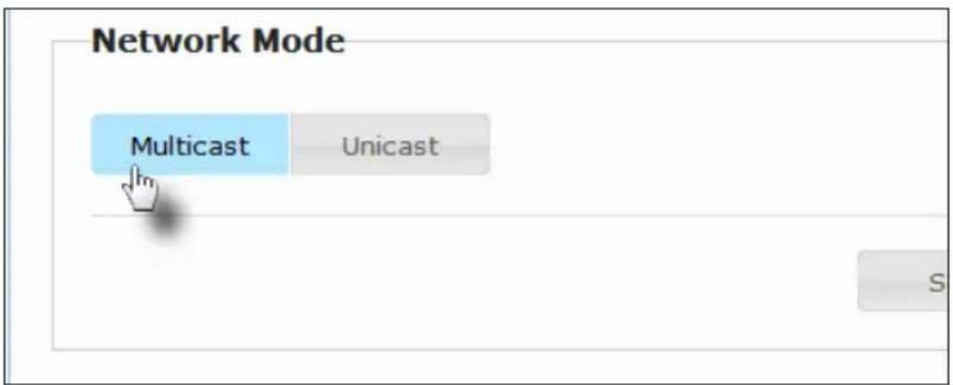
- Click the Save button in the lower-right corner of the Network Mode group.
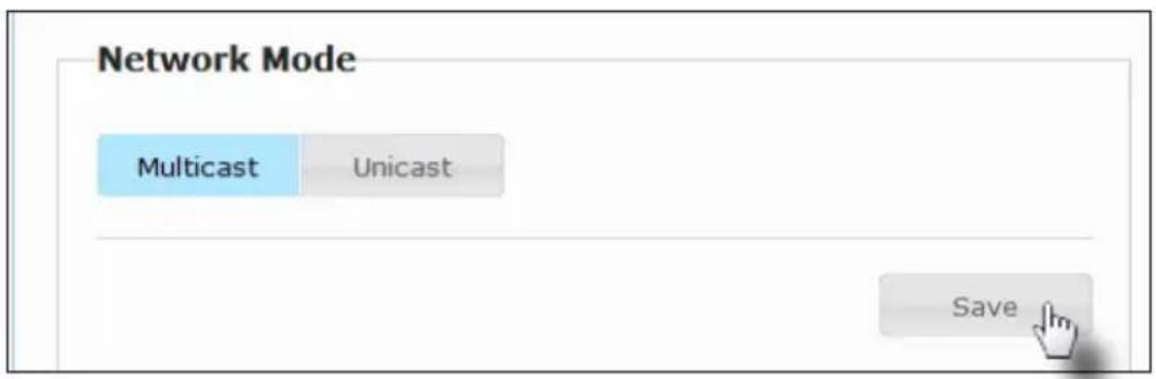
The following message will be displayed, at the top of the page, indicating that the casting mode has been applied to the Sender or Receiver unit.

Success: New casting mode applied.
- Click the Reboot button near the bottom portion of the page to apply the changes.

Warning: Reboot for new settings to take effect.
- Repeat the steps above in order to configure the Sender unit to multicast mode.

Important!
When switching between unicast and multicast modes, both Sender and Receiver units need to be configured identically.
The HD over IP w/ RS-232 and 2-way IR supports RS-232 pass-through, allowing the control of remote RS-232 devices. The Sender and Receiver unit which are being used to pass-through the RS-232 data must be set to the same baud rate as the RS-232 host and client.
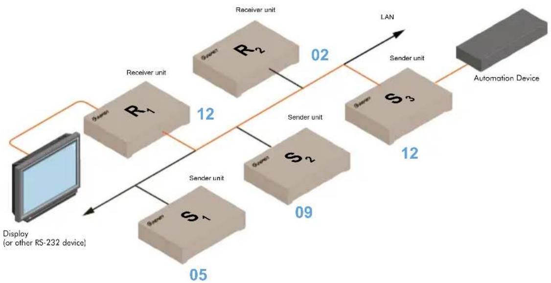
In the example below, a display is connected to Receiver unit R1. This is the RS-232 client. We want to control this product from Sender unit S3, using an automation device (host). The channel numbers are listed in blue. The RS-232 data is shown in orange. The video signals have been removed, from the diagram, for clarity.
Figure 2.9 - Basic RS-232 connection
flowchart
graph LR
    A["Display (or other RS-232 device)"] --> B["Green R1"]
    B --> C["Receiver unit"]
    C --> D["R2"]
    D --> E["02"]
    E --> F["Sender unit"]
    F --> G["S3"]
    G --> H["09"]
    H --> I["Sender unit"]
    I --> J["05"]
    J --> K["Green S1"]
    K --> L["12"]
    L --> M["LAN"]
    M --> N["Sender unit"]
    N --> O["02"]
    O --> P["Sender unit"]
    P --> Q["09"]
    Q --> R["LAN"]
    R --> S["Sender unit"]
    S --> T["02"]
    T --> U["LAN"]
    U --> V["Sender unit"]
    V --> W["09"]
    W --> X["LAN"]
    X --> Y["Sender unit"]
    Y --> Z["02"]
    Z --> AA["LAN"]
    AA --> AB["Sender unit"]
    AB --> AC["09"]
    AC --> AD["LAN"]
    AD --> AE["Sender unit"]
    AE --> AF["02"]
    AF --> AG["LAN"]
    AG --> AH["Sender unit"]
    AH --> AI["09"]
    AI --> AJ["LAN"]
    AJ --> AK["Sender unit"]
    AK --> AL["02"]
    AL --> AM["LAN"]
    AM --> AN["Sender unit"]
    AN --> AO["09"]
    AO --> AP["LAN"]
    AP --> AQ["Sender unit"]
    AQ --> AR["02"]
    AR --> AS["LAN"]
    AS --> AT["Sender unit"]
    AT --> AU["09"]
    AU --> AV["LAN"]
    AV --> AW["Sender unit"]
    AW --> AX["02"]
    AX --> AY["LAN"]
    AY --> AZ["Sender unit"]
    AZ --> BA["09"]
    BA --> BB["LAN"]
    BB --> BC["Sender unit"]
    BC --> BD["02"]
    BD --> BE["LAN"]
    BE --> BF["Sender unit"]
    BF --> BG["09"]
    BG --> BH["LAN"]
    BH --> BI["Sender unit"]
    BI --> BJ["02"]
    BJ --> BK["LAN"]
    BK --> BL["Sender unit"]
    BL --> BM["09"]
    BM --> BN["LAN"]
    BN --> BO["Sender unit"]
    BO --> BP["02"]
    BP --> BQ["LAN"]
    BQ --> BR["Sender unit"]
    BR --> BS["09"]
    BS --> BT["LAN"]
    BT --> BU["Sender unit"]
    BU --> BV["02"]
    BV --> BW["LAN"]
    BW --> BX["Sender unit"]
    BX --> BY["09"]
    BY --> BZ["LAN"]
    BZ --> CA["Sender unit"]
    CA --> CB["02"]
    CB --> CC["LAN"]
    CC --> CD["Sender unit"]
    CD --> CE["09"]
    CE --> CF["LAN"]
    CF --> CG["Sender unit"]
    CG --> CH["02"]
    CH --> CI["LAN"]
    CI --> CJ["Sender unit"]
    CJ --> CK["09"]
    CK --> CL["LAN"]
- Connect the RS-232 automation device to the desired Sender unit.
- Connect the display (or other RS-232 device) to the desired Receiver unit.
- Consult the User Manual for the client device for the proper RS-232 settings. For example, our display device requires the following RS-232 settings:
Table 2.1: Setting for an example display (client) device.
| Description Setting | |
| Baud rate | 19200 |
| Data bits | 8 |
| Parity | None |
| Stop bits | 1 |
| Hardware flow control | None |
(continued on next page)
- Access the Web interface for both the Sender and Receiver unit.
- Login as Administrator.
- Click the Functions tab.
- Locate the Serial over IP group and change the RS-232 settings to match the settings of the RS-232 device that is being used. In this case, we need to use the settings from Table 2.1:
Baudrate Setting for Type 2:
Baudrate: 19200

Data bits: 8

Parity: None

- Make sure that the Enable Serial over IP box is checked.
Serial over IP
Enable Serial over IP
Baudrate Setting for Type 2:
- Click the Save button in the lower-right corner of the Serial over IP group.
- The following message will be displayed, at the top of the page, indicating that the new Serial over IP options have been applied.
i Success: New Serial over IP options applied.
- Click the Reboot button near the bottom portion of the page to apply the changes.
If the unit is not rebooted within a certain period of time, the following message will be displayed:
⚠ Warning: Reboot for new settings to take effect.
- Repeat steps 1 - 7 for the Receiver unit.
RS-232 under Unicast Mode
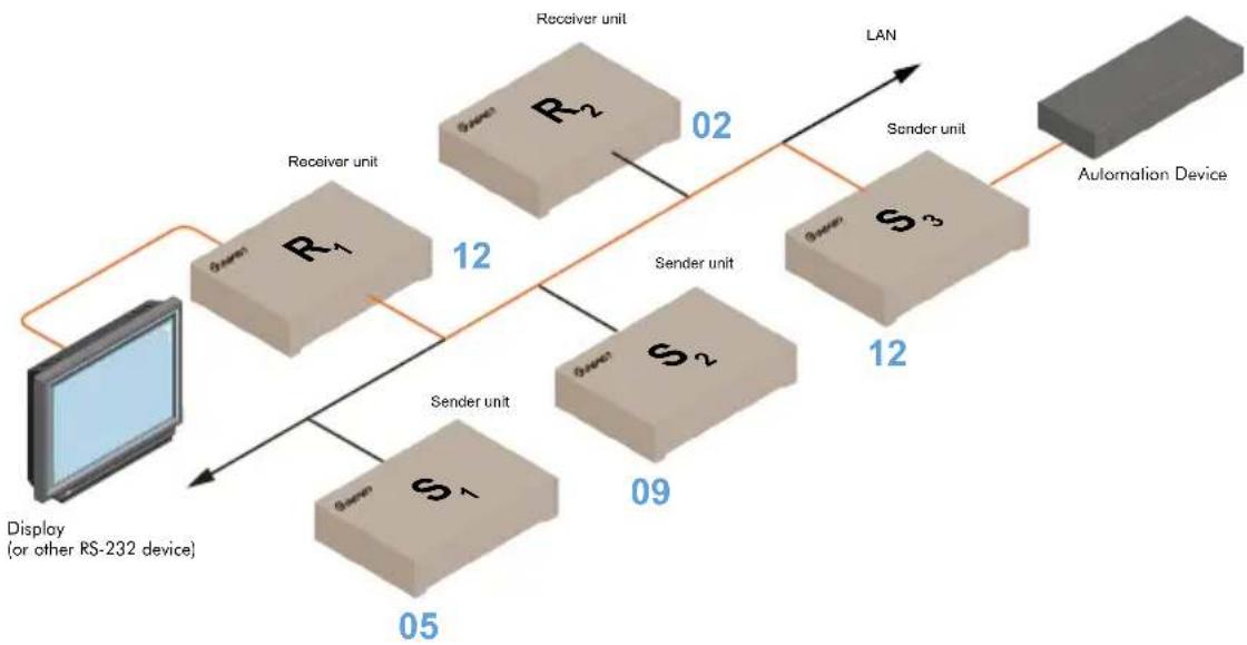
In unicast mode, a Sender unit will be able to communicate with only one Receiver unit at a time.
Figure 2.10 - In unicast mode, the host can talk to only one RS-232 device at a time.
flowchart
graph TD
    A["Monitor"] --> B["Display (or other RS-232 device)"]
    B --> C["Receiver unit R1"]
    C --> D["Sender unit S1"]
    D --> E["Receiver unit R2"]
    E --> F["Sender unit S2"]
    F --> G["Receiver unit R3"]
    G --> H["Sender unit S3"]
    H --> I["LAN"]
    I --> J["Automation Device"]
    C -->|12| E
    D -->|09| F
    E -->|02| G
    F -->|12| H
RS-232 under Multicast Mode
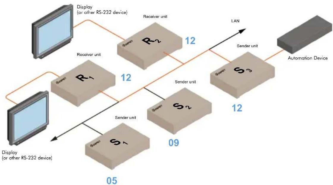
In multicast mode, a Sender unit can communicate with multiple Receiver units simultaneously.
Figure 2.11 - In multicast mode, the host can talk to multiple RS-232 devices.
flowchart
graph TD
    A["Display (or other RS-232 device)"] --> B["Receiver unit"]
    B --> C["R1"]
    B --> D["S1"]
    C --> E["Sender unit"]
    D --> F["Sender unit"]
    E --> G["R2"]
    F --> H["S2"]
    G --> I["LAN"]
    H --> J["Sender unit"]
    I --> K["Automation Device"]
    J --> L["09"]
    K --> M["12"]
    L --> N["12"]
    M --> O["12"]
    N --> P["12"]
    O --> Q["05"]
Any Sender or Receiver unit can be reset to factory-default settings using the Web interface. If the Web interface for a Sender or Receiver unit cannot be accessed, then refer to Manual Reset Procedure (page 56).

Warning!
The following procedure will reset a Sender or Receiver unit to factory-default settings. All current configuration information will be lost.
- Access the Web interface for the Sender and Receiver unit. The password must be set for each Sender and Receiver unit.
- Log in as Administrator.
- Click the System tab.
- Click the Reset button.
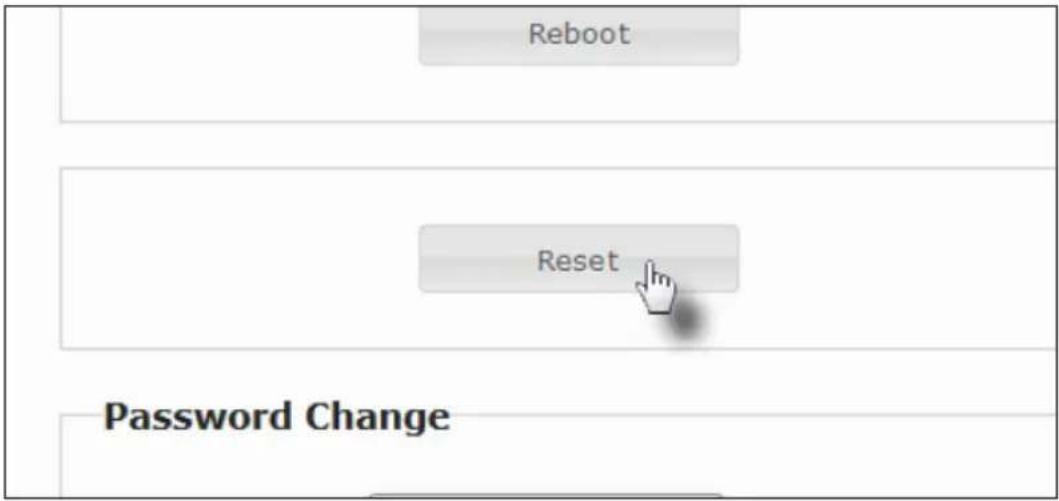
- The following message will be displayed in the Web interface, as the unit is reset. When the unit is reset, it will automatically reboot.
Rebooting...
When a Sender or Receiver unit is reset, it will be set to Auto IP mode. The unit that was reset will now have a different IP address. To display the new IP address, refer to Displaying the IP Address (page 40).
- The reset process is complete.
HD over IP
w/ RS-232 and 2-way IR
3 Appendix
Upgrading the Firmware....44
Web Interface Summary......47
Login tab 47
Network tab 48
Functions tab....50
System tab - Version Information.... 52
System tab - Update Firmware 54
System tab - Command Mode 55
Manual Reset Procedure.... 56
Surface Mounting Instructions....57
Network Cable Diagram 58
Specifications 59
Index......60
- Download the latest firmware from the Gefen Web site.
- Extract the contents of the .zip file to the desktop on your computer. There will be two firmware files:
TX_host_webfwh_[version].bin (Sender unit) RX_client_webfwc_[version].bin (Receiver unit)
-
Access the Web interface for the Sender and Receiver unit. Each unit must be updated separately.
-
Log in as Administrator.
-
Click the System tab. The current firmware version will be displayed under the Gefen logo.
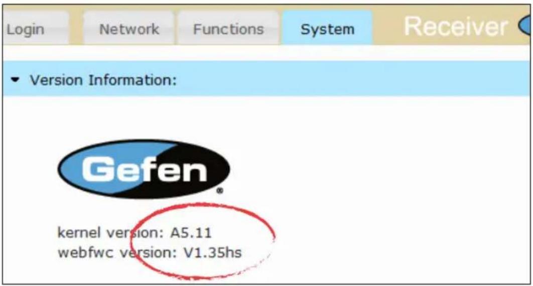
- Click the Update Firmware tab, near the bottom of the page.
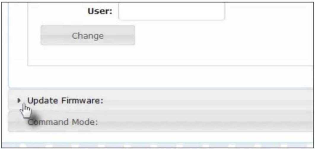
- Click the Browse... button and select the correct firmware file for the unit.
The order in which the Sender and Receiver units are updated is not important. In this example, we are updating the firmware for the Receiver unit.
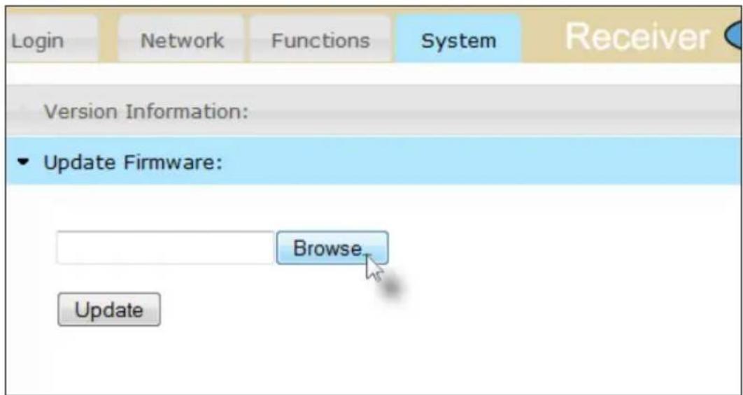
- Click the Update button.
- After a few moments, the Web interface will indicate that the firmware update process has started. The current progress will be displayed.
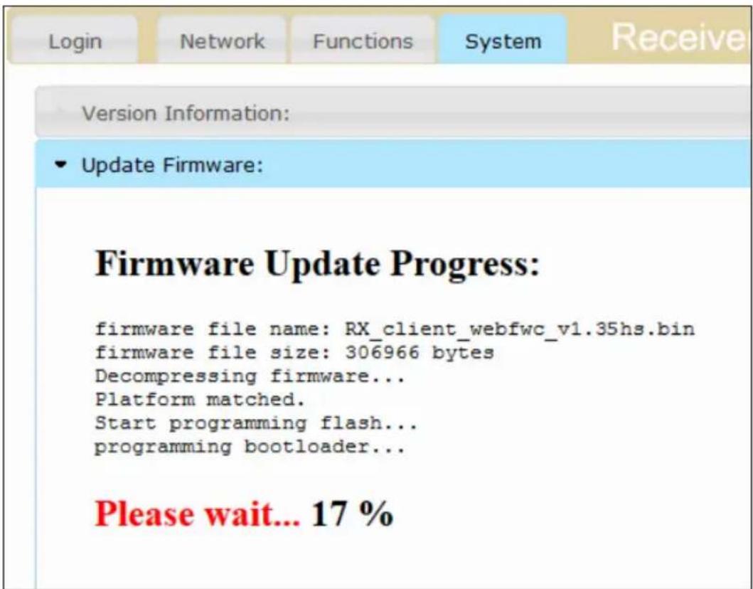
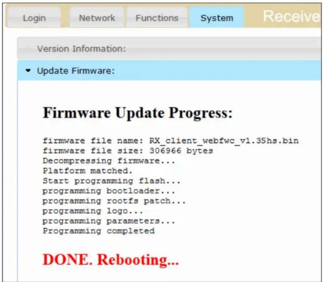
After the firmware has been updated, the unit will automatically reboot.
If the Sender or Receiver unit was in Auto IP mode, the IP address will be changed. To get the new IP address, refer to Displaying the IP Address (page 46).
- The firmware update process is complete.
- Repeat steps 3 - 9 for each Sender and Receiver unit.
Login tab
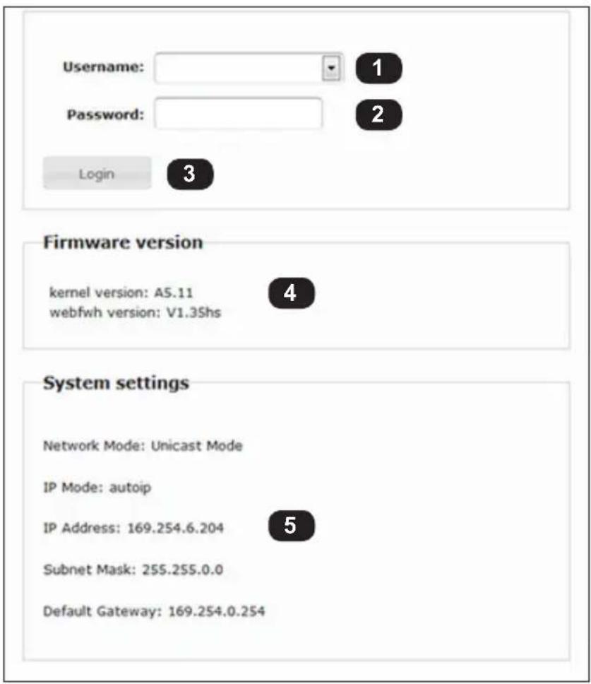
1 Username
Select the desired username from the drop-down list. See Login Procedure (page 16) for details.
2 Password
Enter the password for the selected username. The default password for Administrator is admin. The default password for User is user. Passwords are case-sensitive.
3 Login
Click this button to login once the with the selected username and password.
4 Firmware version
Displays the current firmware version of the Sender unit.
5 System settings
Displays the network mode, IP mode, IP address, subnet mask, and gateway IP of the Sender unit.
Network tab
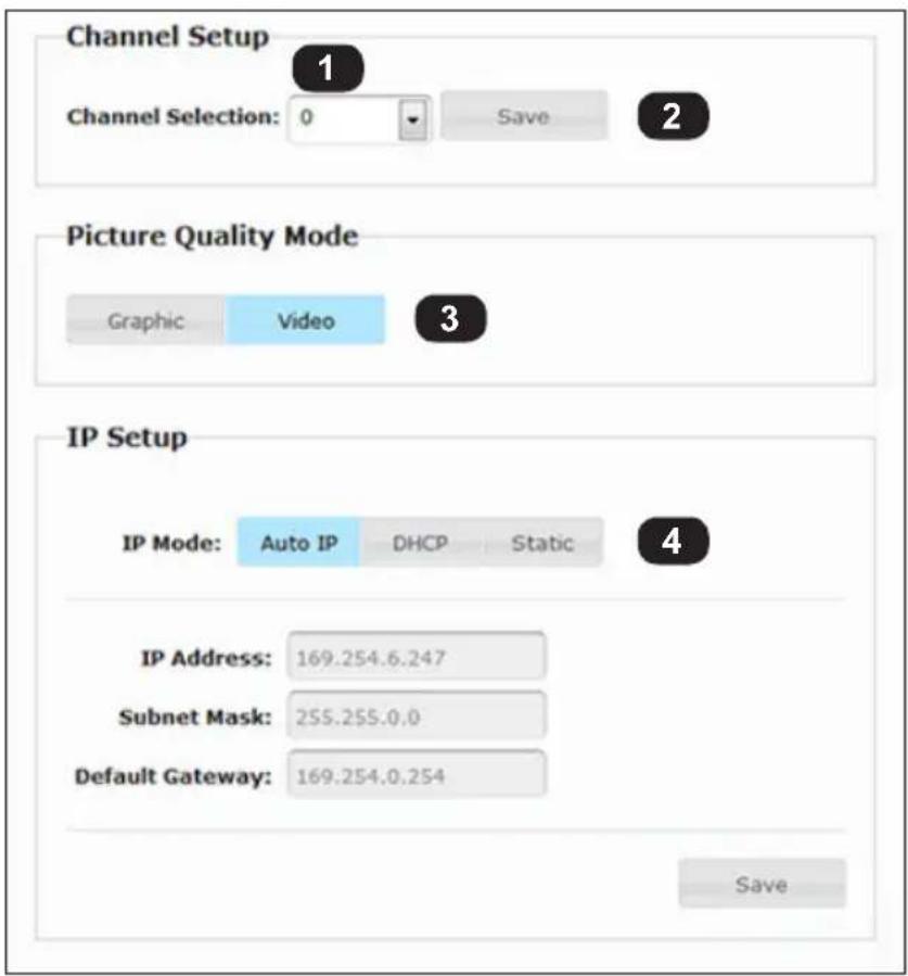
1 Channel Selection
Select the desired channel from the drop-down list. See Setting the Video Channel (page 20) for more information.
2 Save
Click the Save button to save the channel selection.
3 Picture Quality Mode (Sender unit only)
Click the desired button to select the picture quality mode. See Picture Quality Mode (page 27) for more information.
4 IP Mode
Click the desired button to select the IP mode. See Setting the IP Mode (page 22) for more information.
(continued on next page)
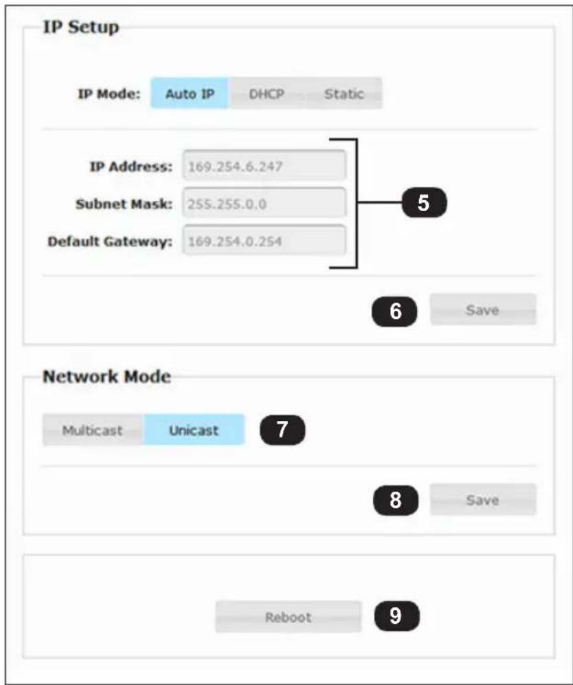
5 Address fields
These fields must be completed when using Static IP mode, only. See Setting the IP Mode (page 22) for details.
6 Save
Click the Save button to save the channel selection.
7 Network Mode
Click the desired button to select the network mode. Click the Save button to save the network mode selection. See Unicast and Multicast Modes (page 30) for more information.
8 Save
Click the Save button to save the network mode setting.
9 Reboot
Click this button to reboot the unit.
Functions tab
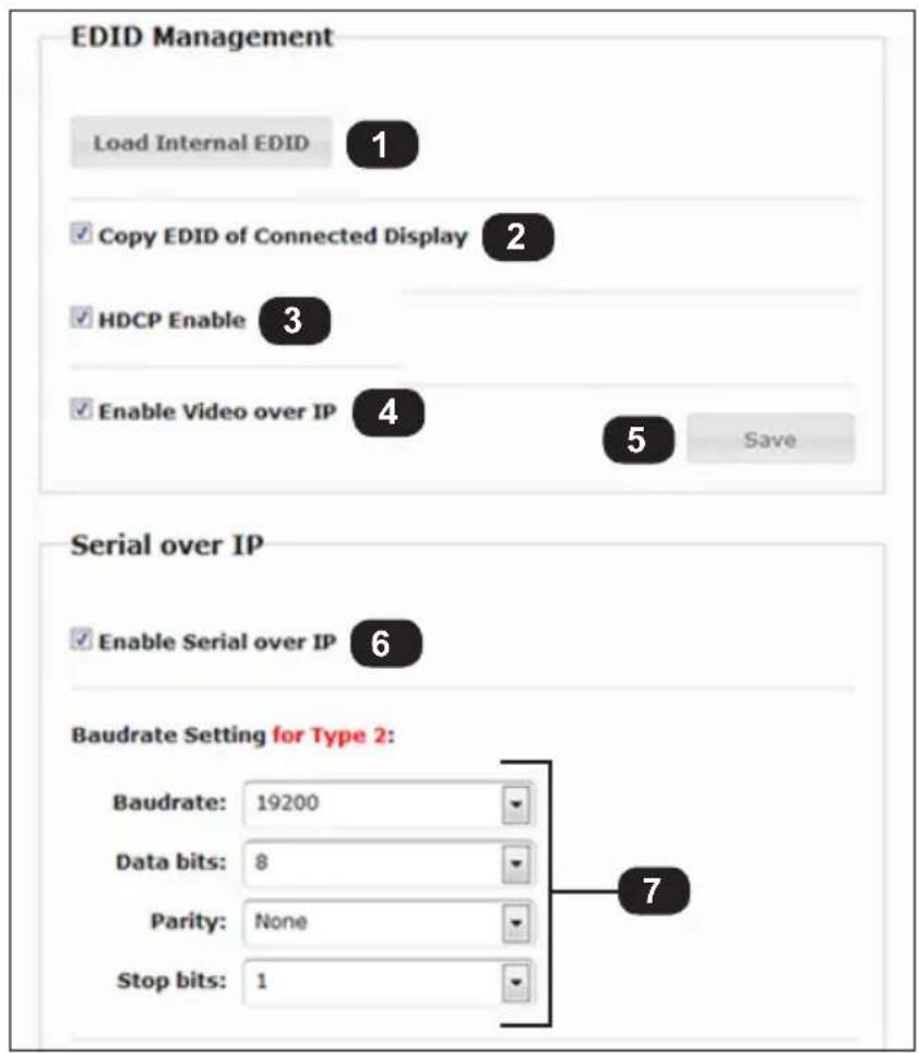
1 Load Internal EDID (Sender unit only)
Click this button to use the internal EDID. See EDID Management (page 28) for details.
2 Copy EDID of Connected Display (Receiver unit only)
When enabled (checked), the Sender unit will use the downstream EDID. See EDID Management (page 28) for details.
3 HDCP Enable (Sender unit only)
Controls the transmission of HDCP content from the source device. See Enabling or Disabling HDCP (page 26) for details.
4 Enable Video over IP
Controls the video masking on the Receiver unit. See Enabling or Disabling Video over IP (page 25) for details.
(continued on next page)
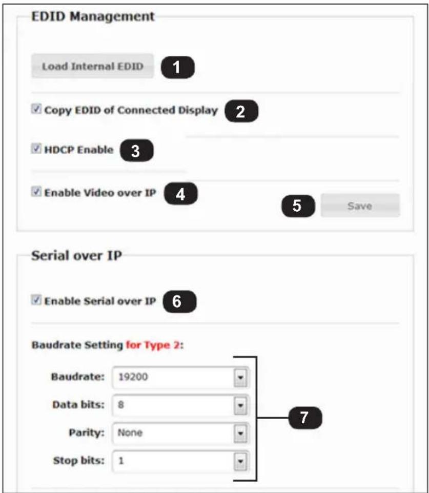
5 Save
Click this button to save the EDID Management settings.
6 Enable Serial over IP
Enables / disables RS-232 transmission. See Using RS-232 (page 37) for details.
7 Baudrate Settings
Use these drop-down boxes to select the serial port settings of the RS-232 client. See Using RS-232 (page 37) for more information.
System tab - Version Information
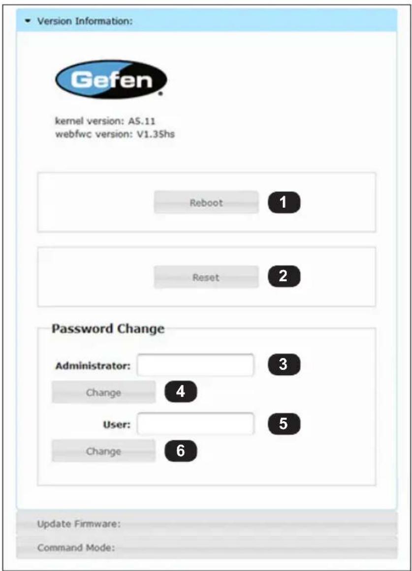
1 Reboot
Click this button to reboot the unit. Rebooting a unit may be required after applying new settings.
2 Reset
Click this button to reset the current unit to factory-default settings. See Resetting a Unit (page 40) for details.
3 Administrator
Type the new Administrator password in this field. Passwords are case-sensitive. Refer to Setting the Password (page 19) for details.
(continued on next page)
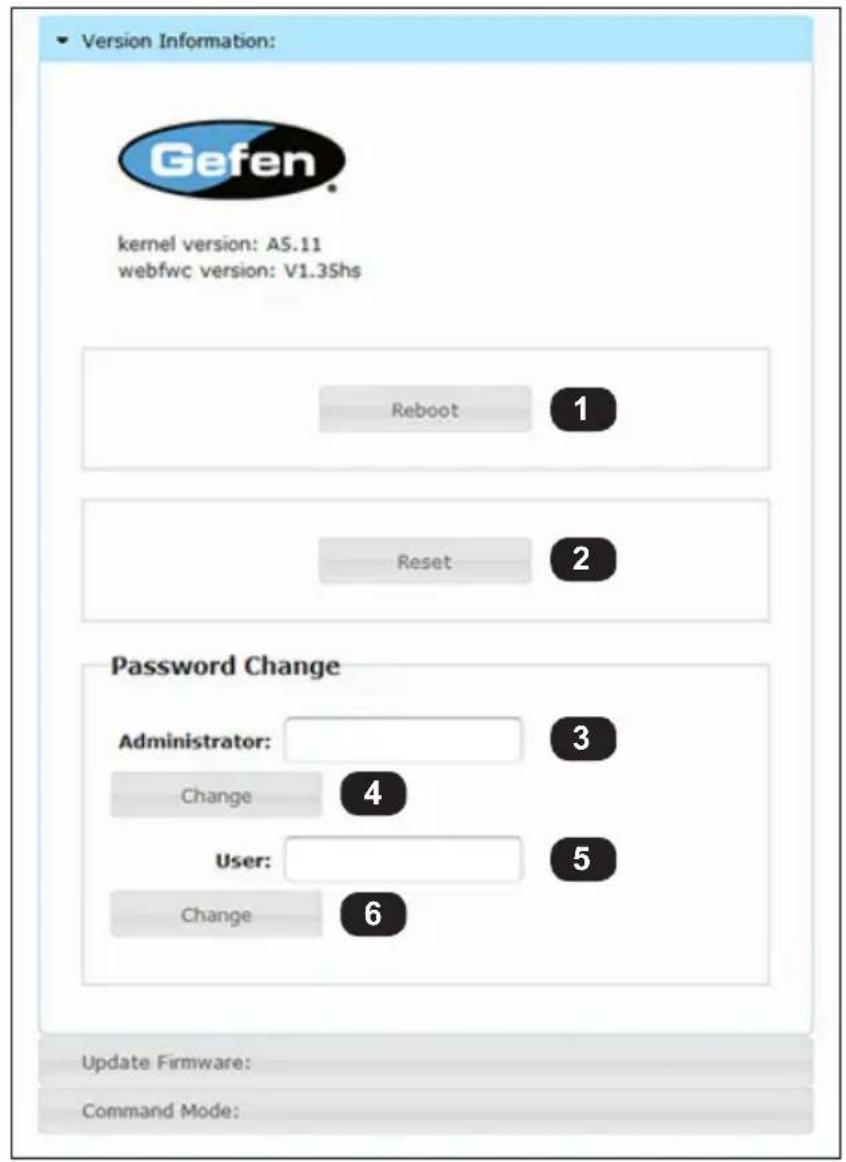
4 Change
Click this button to accept the new Administrator password.
5 User
Type the new User password in this field. Passwords are case-sensitive. Refer to Setting the Password (page 19) for details.
6 Change
Click this button to accept the new User password.
System tab - Update Firmware
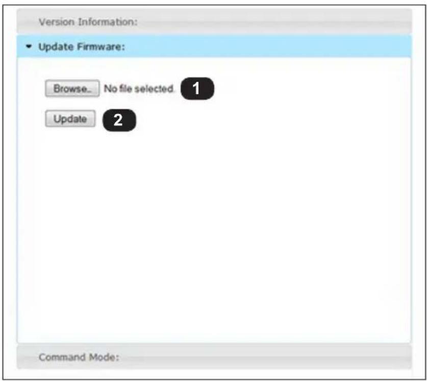
1 Browse...
Click this button to select the firmware file. See Upgrading the Firmware (page 44) for details.
2 Update
Click this button to begin the firmware upgrade process.
System tab - Command Mode
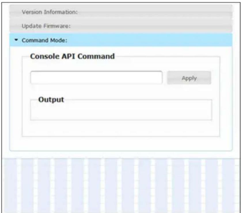
This section of the Web interface is for Technical Support and/or engineering use, only.

Warning!
The following procedure will reset a Sender or Receiver unit to factory-default settings. All current configuration information will be lost.
- Disconnect the power from the unit.
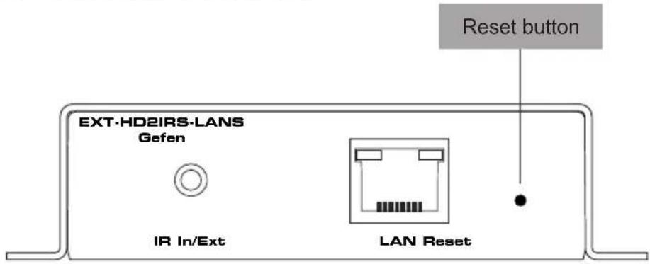
- Press and hold the Reset button using the end of a paperclip or other sharp pointed object.
- While depressing the Reset button, reconnect the power.
- The Power LED indicator will begin to flash.
- Wait until both the Power and Link LED indicators begin to alternately flash.
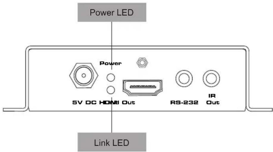
- Release the Reset button.
- Disconnect the power once again, then reconnect the power.
- The unit is now reset to factory-default settings.
- Repeat the above process for each Sender / Receiver unit.
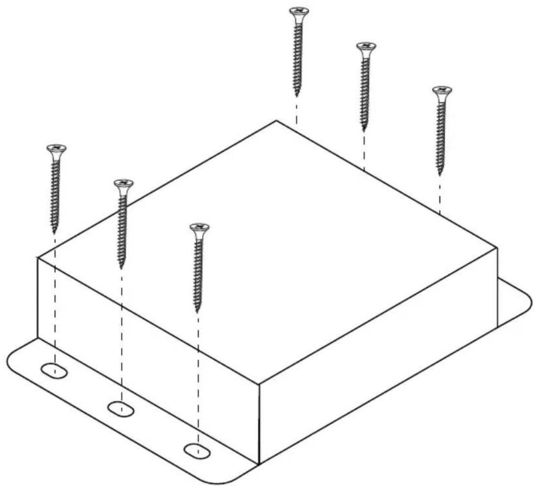
The Sender and Receiver units can be mounted on any flat surface, as shown below (screws not included). There should be an inch or two of clearance between the edges of the unit and any walls or vertical surfaces to allow for enough clearance for connection and disconnection of the HDMI cables.
For installation on a drywall surface, use a #6 drywall screw. When installing, it is recommended to use the center hole on a stud.
natural_image
Isometric line drawing of a rectangular electronic component with six screws inserted, no text or symbols presentFront of RJ-45 Connector
natural_image
Pure diagram of a mechanical or electrical component with no text, numbers, or symbols visible12345678
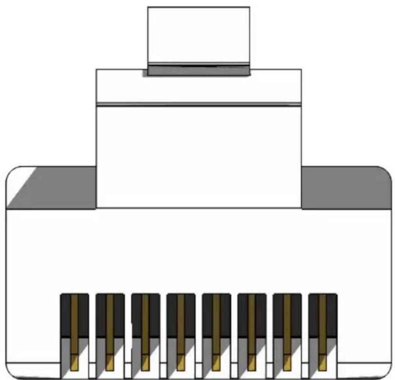
Gefen recommends the TIA/EIA-568-B wiring option. Use the following table when terminating cables in the field.
Pin Color Description
| 1 Orange / White TD+ (Transmit Data, positive differential signal) |
| 2 Orange TD- (Transmit Data, negative differential signal) |
| 3 Green / White RD+ (Receive Data, positive differential signal) |
| 4 Blue Unused |
| 5 Blue / White Unused |
| 6 Green RD- (Receive Data, negative differential signal) |
| 7 Brown / White Unused |
| 8 Brown / White Unused |
Shielded (STP) CAT-5 or CAT-6 is recommended. However, unshielded (UTP) CAT-5 or CAT-6 is acceptable. CAT-5, CAT-5e, and CAT-6 cabling comes in stranded and solid core types. Gefen recommends using solid core cabling. CAT-6 cable is also recommended.
It is recommended to use one continuous run from one end to the other. Patch cable is not recommended.
Supported Formats
| Video • 1920 x 1200 (WUXGA) | • 1080p Full HD• 2K |
| Audio • 7.1 Linear PCM | • Dolby® TrueHD• DTS-HD Master AudioTM |
Connectors, Indicators, and Controls
| HDMI In (Sender) • 1 x HDMI Type A, 19-pin, female |
| HDMI Out (Receiver) • 1 x HDMI Type A, 19-pin, female |
| Power (Sender / Receiver) • 1 x Locking-type |
| LAN (Sender / Receiver) • 1 x RJ-45, shielded, female |
| IR In/Ext (Sender / Receiver) • 1 x 3.5mm, female |
| IR Out (Sender / Receiver) • 1 x 3.5mm, female |
| RS-232 (Sender / Receiver) • 1 x 3.5mm, female |
| Power Indicator (Sender / Receiver) • 1 x LED, green |
| Link Indicator (Sender / Receiver) • 1 x LED, amber |
| Reset Button • 1 x Tact-type, recessed |
Operational
| Maximum Pixel Clock • 165 MHz | |
| Maximum TMDS Clock | • 225 MHz |
| Power Input | • 5V DC |
| Power Consumption (Sender) | • 6 Watts (max.) |
| Power Consumption (Receiver) | • 4 Watts (max.) |
| Operating Temperature | • +32 to +122 °F (0 to +50 °C) |
| Storage Temperature | • -20 to +85 °F (-28 to 29 °C) |
| Operating Humidity (RH) | • +10 to +90%, non-condensing |
| Storage Humidity (RH) | • 0 to +95%, non-condensing |
| MTBF | • 50000 Hours |
Physical
| Dimensions (W x H x D)(Sender / Receiver) | • 4.3" x 1" x 3.2"(110mm x 26mm x 80mm) |
| Unit Weight (Sender / Receiver) | • 0.4 lb (0.2 kg) |
A
Administrator default password 17 login 16
Auto IP mode address range 6 using 22
B
Bidirectional IR Control 12
C
Configuration multicast mode 35 unicast mode 30
E
EDID Management using the downstream EDID 29 using the internal EDID 28
F
Features vi
H
HDCP disabling 26 enabling 26
|
IP Address displaying 15 setting 24
IP Mode setting 22
IR Control. See Bidirectional IR Control
M
Mounting Instructions 57 Multicast Mode configuring 35
N
Network Cable Diagram 58
P
Packing List vii Picture Quality Mode 27
R
Receiver Unit 4 Reset Procedure manual 56 using the web interface 40
RS-232 multicast mode 39 unicast mode 39 using 37
S
Safety Instructions ii Sender Unit 2 Specifications 59
T
Table of Contents viii Technical Support iv
U
Unicast Mode configuring 30 switching between sender units 32
Upgrading the Firmware 44 User default password 17 login 16 Using a Direct Connection 6
V
Video Channel setting 20 Video over IP enabling / disabling 25
W
Warranty Information iii
Web Interface
enabling or disabling HDCP 26
enabling or disabling video over IP 25
functions tab 50
login procedure 16
login tab 47
network tab 48
picture quality mode 27
setting the IP address 24
setting the IP mode 22
setting the password 19
setting the video channel 20
system tab
command mode 55
update firmware 54
version information 52
viewing system settings 18
Wiring Diagram 8

GEFEN
20600 Nordhoff St., Chatsworth CA 91311
1-800-545-6900 818-772-9100 fax: 818-772-9120
www.gefen.com support@gefen.com
- w/ RS-232 and 2-way IR
- Technical Support
- Fax
- Web
- Mailing Address
- Product Registration
- Features
- Packing List
- Sender Package (EXT-HD2IRS-LAN-TX)
- Receiver Package (EXT-HD2IRS-LAN-RX)
- Getting Started
- Basic Operation
- Appendix
- HD over IP
- Using a Direct Connection
- Local Area Network (LAN) Connection
- Important!
- Additional Connections
- ▶ IR
- RS-232
- ▶ Power
- Sample Wiring Diagram
- Controlling the Source from the Viewing Location
- Controlling the Display from the Source Location
- Controlling the Source / Display from Different Locations
- Information
- Login Procedure
- Viewing System Settings
- Firmware version
- System settings
- Setting the Password
- Setting the Video Channel
- Setting the IP Mode
- Setting the IP Address
- Enabling or Disabling Video over IP
- Enabling or Disabling HDCP
- Picture Quality Mode
- Using the Internal EDID
- Using the Downstream EDID
- Warning!
- Configuring Unicast Mode
- Tip
- Switching between Sender units in Unicast mode
- Configuring Multicast Mode
- RS-232 under Unicast Mode
- RS-232 under Multicast Mode
- Login tab
- Username
- Password
- Login
- Firmware version
- System settings
- Network tab
- Channel Selection
- Save
- Picture Quality Mode (Sender unit only)
- IP Mode
- Address fields
- Save
- Network Mode
- Save
- Reboot
- Functions tab
- Load Internal EDID (Sender unit only)
- Copy EDID of Connected Display (Receiver unit only)
- HDCP Enable (Sender unit only)
- Enable Video over IP
- Save
- Enable Serial over IP
- Baudrate Settings
- System tab - Version Information
- Reboot
- Reset
- Administrator
- Change
- User
- Change
- System tab - Update Firmware
- Browse...
- Update
- System tab - Command Mode
- A
- B
- C
- E
- F
- H
- |
- M
- N
- P
- R
- S
- T
- U
- V
- W
- GEFEN
Brand : Gefen
Model : EXT-HD2IRS-LAN-RX
Category : AV Extender