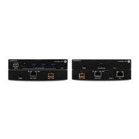
AT-USB-EX350-KIT - Extendeur de données Atlona - Free user manual and instructions
Find the device manual for free AT-USB-EX350-KIT Atlona in PDF.


| Product Type | USB 3.0 Extender Kit |
| Brand | Atlona |
| Model | AT-USB-EX350-KIT |
| Dimensions (Transmitter) | 4.5 x 3.3 x 1.0 in (115 x 85 x 25 mm) |
| Dimensions (Receiver) | 4.5 x 3.3 x 1.0 in (115 x 85 x 25 mm) |
| Weight (Transmitter) | 6.7 oz (190 g) |
| Weight (Receiver) | 6.7 oz (190 g) |
| Power Supply | External 5V DC, 2A (included) |
| Power Consumption | 5W (max) |
| USB Interface | USB 3.0 Type-A (host) to USB 3.0 Type-A (device) |
| Maximum Extension Distance | 350 ft (106 m) via CAT6/7 cable |
| Data Transfer Rate | Up to 5 Gbps |
| Supported USB Devices | Flash drives, webcams, keyboards, mice, printers, etc. |
| Cable Type Required | Shielded CAT6 or CAT7 (STP) |
| LED Indicators | Power, Link, Activity |
| Operating Temperature | 32°F to 104°F (0°C to 40°C) |
| Storage Temperature | -4°F to 140°F (-20°C to 60°C) |
| Humidity | 20% to 80% RH (non-condensing) |
| Maintenance | Wipe with dry cloth; avoid liquids and abrasives |
| Safety | CE, FCC, RoHS compliant |
| Spare Parts / Repairability | Power adapter available separately; no user-serviceable parts |
| Warranty | 2 years limited |
| Included Accessories | Transmitter, Receiver, 2 power adapters, user manual |
Frequently Asked Questions - AT-USB-EX350-KIT Atlona
User questions about AT-USB-EX350-KIT Atlona
0 question about this device. Answer the ones you know or ask your own.
Ask a new question about this device
Download the instructions for your Extendeur de données in PDF format for free! Find your manual AT-USB-EX350-KIT - Atlona and take your electronic device back in hand. On this page are published all the documents necessary for the use of your device. AT-USB-EX350-KIT by Atlona.
USER MANUAL AT-USB-EX350-KIT Atlona
| Version Release Date Notes | |
| 1 Mar 2025 Initial release |
Sales, Marketing, and Customer Support
Main Office
Atlona Incorporated
70 Daggett Drive
San Jose, CA 95134
United States
Office: +1.408.962.0515
Sales and Customer Service Hours
Monday - Friday: 6:00 a.m. - 4:30 p.m. (PST)
https://atlona.com/
International Headquarters
Atlona International AG
Tödistrasse 18
8002 Zürich
Switzerland
Office: +41.43.508.4321
Sales and Customer Service Hours
Monday - Friday: 09:00 - 17:00 (UTC +1)
Operating Notes

IMPORTANT: Visit https://www.atlona.com/product/at-usb-ex350-kit for the latest firmware updates and User Manual.
Warranty

To view the product warranty, use the following link or QR code:
https://atlona.com/warranty/.
Safety and Certification
CAUTION
RISK OF ELECTRIC SHOCK
DO NOT OPEN
CAUTION: TO REDUCT THE RISK OF
ELECTRIC SHOCK
DO NOT OPEN ENCLOSURE OR EXPOSE
TO RAIN OR MOISTURE
NO USER-SERVICEABLE PARTS
INSIDE REFER SERVICING TO
QUALIFIED SERVICE PERSONNEL.

The exclamation point within an equilateral triangle is intended to alert the user to the presence of important operating and maintenance instructions in the literature accompanying the product.

The information bubble is intended to alert the user to helpful or optional operational instructions in the literature accompanying the product.
- Read these instructions.
- Keep these instructions.
- Heed all warnings.
- Follow all instructions.
- Do not use this product near water.
- Clean only with a dry cloth.
- Do not block any ventilation openings. Install in accordance with the manufacturer's instructions.
-
Do not install or place this product near any heat sources such as radiators, heat registers, stoves, or other apparatus (including amplifiers) that produce heat.
-
Do not defeat the safety purpose of a polarized or grounding-type plug. A polarized plug has two blades with one wider than the other. A grounding type plug has two blades and a third grounding prong. The wide blade or the third prong are provided for your safety. If the provided plug does not fit into your outlet, consult an electrician for replacement of the obsolete outlet.
- Protect the power cord from being walked on or pinched particularly at plugs, convenience receptacles, and the point where they exit from the product.
- Only use attachments/accessories specified by Atlona.
- To reduce the risk of electric shock and/or damage to this product, never handle or touch this unit or power cord if your hands are wet or damp. Do not expose this product to rain or moisture.
- Unplug this product during lightning storms or when unused for long periods of time.
- Refer all servicing to qualified service personnel. Servicing is required when the product has been damaged in any way, such as power-supply cord or plug is damaged, liquid has been spilled or objects have fallen into the product, the product has been exposed to rain or moisture, does not operate normally, or has been dropped.
CE
FC
cULus
CCC
√
[RECYC CIRCUM SYMBOL]

FCC Compliance
FCC Compliance and Advisory Statement: This hardware device complies with Part 15 of the FCC rules. Operation is subject to the following two conditions: 1) this device may not cause harmful interference, and 2) this device must accept any interference received including interference that may cause undesired operation. This equipment has been tested and found to comply with the limits for a Class A digital device, pursuant to Part 15 of the FCC Rules. These limits are designed to provide reasonable protection against harmful interference in a commercial installation. This equipment generates, uses, and can radiate radio frequency energy and, if not installed or used in accordance with the instructions, may cause harmful interference to radio communications. However there is no guarantee that interference will not occur in a particular installation. If this equipment does cause harmful interference to radio or television reception, which can be determined by turning the equipment off and on, the user is encouraged to try to correct the interference by one or more of the following measures: 1) reorient or relocate the receiving antenna; 2) increase the separation between the equipment and the receiver; 3) connect the equipment to an outlet on a circuit different from that to which the receiver is connected; 4) consult the dealer or an experienced radio/TV technician for help. Any changes or modifications not expressly approved by the party responsible for compliance could void the user's authority to operate the equipment. Where shielded interface cables have been provided with the product or specified additional components or accessories elsewhere defined to be used with the installation of the product, they must be used in order to ensure compliance with FCC regulations.
Copyright, Trademark, and Registration
© 2025 Atlona Inc. All rights reserved. "Atlona" and the Atlona logo are registered trademarks of Atlona Inc. Pricing, specifications and availability subject to change without notice. Actual products, product images, and online product images may vary from images shown here.
All other trademark(s), copyright(s), and registered technologies mentioned in this document are the properties of their respective owner(s).
Table of Contents
Introduction 6
Features 6
Package Contents 6
Panel Description 7
AT-USB-EX350-HS 7
AT-USB-EX350-DV 8
Installation 9
Connection Instructions 9
Connection Diagram 10
IP Configuration 11
Automatic Private IP Addressing (APIPA) Mode 11
Device Operation 12
LED Indicators 12
RS-232 Control 13
Logging in to the Web Server 14
Login Registration 14
Logging in after Registration 15
System Settings 16
Obtaining System Information 16
Changing the Administrator Password 17
Network Configuration 18
Setting the IP Mode 18
IEEE 802.1x Authentication 20
Setting the Host Name 23
System Time 24
Setting the Time Zone 24
Assigning an NTP Server 25
Setting the System Time 26
USB Management 28
USB Configuration 28
USB Info 29
RS-232 Control 32
RS-232 Control Settings 32
System Maintenance 33
Updating the Firmware 33
Performing a Factory Reset 33
Rebooting the System 34
Downloading Log Files 35
Configuration and Management Interfaces 36
Web Server 36
Login 36
System > System 37
System > Network 38
System > Time 40
USB Management > USB Configuration 41
USB Management > USB Info 42
Control 45
Maintenance > System 47
Maintenance > Log 48
Appendix 49
Mounting Instructions 49
Updating the Firmware 50
Updating using the Web Server 50
Updating over USB 52
Specifications 53
Introduction
The Atlona AT-USB-EX350-KIT is a data-only USB 3.2 extender kit. It supports simultaneous extension of 5 Gbps USB 3.2 Gen 1 data and 480 Mbps USB 2.0 data up to 330 feet (100 meters) using a single, cost-effective Category 6A U/FTP cable.
The USB-EX350-KIT is ideal for video conferencing or remote instruction applications where high data rate USB components including laptops, computers, cameras, microphones, and speakers are in different areas of the room.
The USB-EX350-KIT is comprised of two endpoints. The host endpoint includes a USB-C port for connection to hosts such as laptops, computers, or other AV equipment that supports USB connectivity including many Omega™ Series products. The device endpoint includes three USB-A ports and one USB-C port for connection to 4K cameras, conferencing bars, microphones, speakers, and other peripherals. Bidirectional remote power allows the kit to be powered by the included power supply connected to either the host or device endpoint.
An Ethernet connection on the host endpoint provides access to advanced integration capabilities including:
• Monitor system and port status for validation and troubleshooting.
- Configure VBUS modes.
• IP to RS-232 translation supporting bi-directional serial control through the device endpoint.
The USB-EX350-KIT is a great solution for extending USB 3.2 Gen 1 data up to 5 Gbps between components at distances greater than is possible with traditional cabling.
Features
- Point-to-point USB extender kit for devices such as cameras, speakers, microphones and other peripherals.
- Extends USB data up to 330 feet (100 meters) using a single Category 6A U/FTP cable.
• Supports USB 3.2 Gen 1 data rates up to 5 Gbps.
• Supports USB 2.0 data rates up to 480 Mbps. - 1 x USB-C interface for host connection.
- 3 x USB Type A and 1 x USB-C for peripheral connections.
- Bidirectional remote power allows the kit to be powered by either the host or device endpoint.
- Ethernet port for monitoring, management, and configuration.
- Individual VBUS control of the USB ports on the device endpoint.
• IP to RS-232 translation for bi-directional RS-232 communications through the device endpoint. - Compact enclosures can be mounted in furniture, behind a display, or above a projector.
- Kit includes host endpoint, device endpoint, power supply, and mounting brackets.
Package Contents
1 x AT-USB-EX350-HS
1 x AT-USB-EX350-DV
1 x 3 ft. USB-A to USB-C cable
1 x 3-pin captive screw connector
4 x Surface mounting brackets
4 x Mounting screws
1 x AC power supply with 2-pin captive screw connector
1 x AC power cord
1 x Insert w/ QR code
Panel Description
AT-USB-EX350-HS

1 PWR
This LED indicator will be green while the unit is powered and operating normally. Refer to LED Indicators (page 12) for more information.
2 USB HOST (5G)
Connect the included USB-C cable from this port to the host device.
3 MGMT
Connect a USB-C cable from this port to a computer to perform firmware updates. Refer to Updating the Firmware (page 50) for more information.
4 LAN
Connect an Ethernet cable from this port to a network switch on the Local Area Network (LAN). This connection is required in order to access the built-in web server.
5 IP MODE
Use a paperclip or another slim object to press and hold this recessed button.
The button serves three functions:
- Firmware Update Mode
Press and hold the button for 5 seconds, then release.
- IP Mode
Press and hold the button for 10 to 15 seconds.
- Factory Reset
Press and hold the button for more than 15 seconds.
6 HDBT-USB3
Connect a category cable (CAT6A U/FTP), up to 330 feet (100 meters), from this port to the HDBT-USB3 port on the AT-USB-EX350-DV.
7 48V / 1.36A
Connect the 2-pin captive screw connector on the included power supply to this power receptacle.
AT-USB-EX350-DV

1 PWR
This LED indicator will be green while the unit is powered and operating normally. Refer to LED Indicators (page 12) for more information.
2 USB DEVICES (5G)
Connect USB devices to these ports. These ports support USB 3.2 Gen 1.
3 RS-232
Connect an RS-232 cable from this port to a control system to enable TCP proxy from the LAN port to the RS-232 port.
4 48V / 1.36A
Connect the 2-pin captive screw connector on the included power supply to this power receptacle.
5 HDBT-USB3
Connect a category cable (CAT6A U/FTP), up to 330 feet (100 meters), from this port to the HDBT-USB3 port on the AT-USB-EX350-HS.
6 DEBUG
Connect a USB-C cable from this port to a computer for debugging and for performing Valens firmware updates.
Installation
Connection Instructions
- Connect a USB cable from the host device to the USB-C HOST port on the AT-USB-EX350-HS. This port supports USB 3.2 data up to 5 Gbps and USB 2.0 data up to 480 Mbps.
Recommended cable types:
• USB Type-A to Type-C (USB 3.2 Gen 1 or higher)
• USB Type-C to Type-C (USB 3.2 Gen 1 or higher)
- Connect up to four USB devices to the USB DEVICES (5G) ports on the AT-USB-EX350-DV. Each port supports USB 3.2 Gen 1 and 5 V / 1.5 A of power.
- Connect a category cable (CAT6A U/FTP) from the HDBT-USB3 port on the AT-USB-EX350-HS to the HDBT-USB3 port on the AT-USB-EX350-DV. Maximum cable length should not exceed 330 feet (100 meters) of CAT6A U/FTP. For maximum lengths of other cable types, refer to the product datasheet.
- OPTIONAL: Connect an Ethernet cable from the LAN port to the network. This is necessary to access the built-in web server, which is used to control and configure the AT-USB-EX350-KIT.
- OPTIONAL: Connect a 3-pin captive screw connector from the RS-232 port to a third-party device to enable TCP proxy via LAN control at the host endpoint.
- Connect the included power supply to the 48V / 1.36A power receptacle on the AT-USB-EX350-HS or AT-USB-EX350-DV.
- Connect the power supply to an available AC outlet.

NOTE: The AT-USB-EX350-KIT supports bidirectional power. The included power supply can be connected to either the AT-USB-EX350-HS or AT-USB-EX350-DV.


Installation
Connection Diagram

flowchart
graph TD
    PC["PC"] -->|USB| ATOME-SW21-TX["AT-OME-SW21-TX"]
    Laptop["Laptop"] -->|USB| ATOME-SW21-TX
    ATOME-SW21-TX -->|USB| AT-CAP-SP100["AT-CAP-SP100"]
    AT-CAP-SP100 -->|USB| AT-USB-EX350-HS["AT-USB-EX350-HS"]
    AT-USB-EX350-HS -->|USB| AT-USB-EX350-DV["AT-USB-EX350-DV"]
    AT-USB-EX350-DV -->|USB| AT-CAP-FC110["AT-CAP-FC110"]
    AT-CAP-FC110 -->|USB| AT-OME-RX["AT-OME-RX"]
    AT-OME-RX -->|USB| AT-CAP-EXRX["AT-OME-RX"]
    AT-CAP-EXRX -->|USB| AT-OME-SW21-TX
    AT-OME-SW21-TX -->|USB/C| PC
    ConfidenceMonitor["Confidence Monitor"] -->|USB| ATOME-SW21-TX
    ATOME-SW21-TX -->|USB/C| PC
IP Configuration
The AT-USB-EX350-KIT is shipped with DHCP enabled. Once connected to a network, the DHCP server (if available), will automatically assign an IP address to the unit. If the AT-USB-EX350-KIT is unable to detect a DHCP server within 15 seconds, then the unit will use a self-assigned IP address within the range of 169.254.xxx.xxx/16. If this occurs, refer to the instructions below. Otherwise, skip to the next page.
Automatic Private IP Addressing (APIPA) Mode
If the AT-USB-EX350-KIT is unable to detect a DHCP server within 15 seconds, when set to DHCP mode, then Automatic Private IP Addressing (APIPA) will be used to assign an address within the IPv4 address block 169.254.xxx.xxx/16. If a DHCP server is detected while in APIPA mode, then the AT-USB-EX350-KIT will be assigned an address from the DHCP server pool. To manually configure the IP address, connect an Ethernet cable directly from the LAN port of the Host Endpoint of the AT-USB-EX350-KIT to the LAN port of a computer, then do the following:
- Change the IP address of the computer to an unused IP address within the range 169.254.xxx.xxx/16. The computer must not be assigned the same address as the AT-USB-EX350-KIT.
- Click Start > Settings > Control Panel > Network and Sharing Center.
- Click Change adapter settings.
- Right-click on the adapter that is used to establish a wired connection to the network, and select Properties from the context menu.
- Under the Ethernet Properties dialog box, select Internet Protocol Version 4 and then click the Properties button. Click the Use the following IP address radio button.

IMPORTANT: Before continuing, write down the current IP settings in order to restore them, later. If Obtain an IP address automatically and Obtain DNS server automatically are selected, then this step is not required.
-
Enter the desired static IP address or the IP address provided by the network administrator. If the computer does not require Internet access or if a statically-assigned IP address is being used, then an address within the IPv4 address block 169.254.xxx.xxx/16 can be entered.
-
Set the subnet mask to 255.255.0.0.
-
Click the OK button then close all Control Panel windows.
-
Log in to the built-in web server to set a static IP address that can be used with the network. Contact a system administrator, if necessary. Refer to Setting the IP Mode (page 18) for more information.
Device Operation
LED Indicators
The PWR indicator on both the AT-USB-EX350-HS and AT-USB-EX350-DV provide power state information on both the AT-USB-EX350-HS and AT-USB-EX350-DV.
| PWR Description | |
| Solid green Unit is powered.Off Unit is not powered. | |
| Verify that the 2-pin captive screw connector is firmly secured to the power receptacle.Make sure that the power supply is plugged into a live AC outlet. | |
| LINK Description | |
| Solid green Link exists between host and device endpoints. | |
| Off Link does not exist between host and device endpoints or device is not powered. | |
| ·Verify that there is a category cable connecting the two endpoints.·If a cable is connecting the two units, check to confirm that the cable is correctly terminated on both ends.·Verify that the system is powered. | |
| FW Description | |
| 1 Hz Blinking Amber 1 Hz Blinking Amber - Unit is booted and operating normally. | |
| 5 Hz Blinking Amber Valens FW has an issue. Contact Atlona Technical Support. | |
| Off Unit is not powered or Valens FW did not load. | |
| · Verify that the system is powered. If it is powered and this LED is off, contact Atlona Technical Support. | |
RS-232 Control
Connect an RS-232 cable from the RS-232 port on the AT-USB-EX350-DV to a device that will be controlled via a serial connection, such as a camera. This connection will be established over the network using a TCP Proxy to the AT-USB-EX350-HS.

Logging in to the Web Server
Most of the AT-USB-EX350-KIT operation is handled through the built-in web server. In order to access the web server, the IP address of the unit must be known.
Login Registration
Before the built-in web server can be accessed the password must be changed.
- Launch the desired web browser and enter the IP address of the AT-USB-EX350-KIT in the address bar.
- The Login page will be displayed.

- Enter Atlona in the provided field.
- Click the LOGIN button.
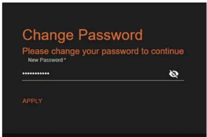
- The Change Password screen will be displayed.
Device Operation
- Enter the desired password in the Password field. By default, the password will be masked. To toggle between password masking and unmasking, click the 🔒 icon.

NOTE: Passwords can be 5 to 32 characters in length and can only contain letters, numbers, dashes, underscores, and periods. The password that is created is referred to as the Admin password. Additional users cannot be created or assigned. This password can be changed, if desired, from within the web server. Refer to Changing the Administrator Password (page 17) for more information.
- Click the Apply button to commit changes.
- The System > System page will be displayed.
Logging in after Registration
- Launch the desired web browser and enter the IP address of the AT-USB-EX350-KIT in the address bar.
- Enter the correct password in the provided field.
- Click the LOGIN button.

- The System > System page will be displayed.
System Settings
The AT-USB-EX350-KIT provides easy access to system configuration through the built-in web server and is the recommended method to adjust network settings.
Obtaining System Information
- Log in to the web server.
- Click System in the side menu bar.
-
Click System in the top menu bar.
-
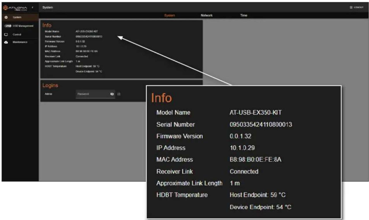
Locate the Info window group to obtain the IP address, MAC address, System Time, Temperature, and various other details about the AT-USB-EX350-KIT.
Device Operation
Changing the Administrator Password
- Log in to the web server.
- Click System in the side menu bar.
- Click System in the top menu bar.
- Locate the Logins window group.

- Enter the new password in the Admin field. By default, the password will be masked. To toggle between password masking and unmasking, click the 🔒 icon.
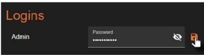
- Click the 📄 icon to commit changes.
Network Configuration
Setting the IP Mode
The AT-USB-EX350-KIT is set to DHCP by default and will receive an IP address from the network's DHCP pool if a DHCP server is available. If no DHCP server is detected, the AT-USB-EX350-KIT will automatically assign itself an APIPA address in the range 169.254.xxx.xxx/16. A static IP address can also be specified.

IMPORTANT: Before assigning a static IP address to the AT-USB-EX350-KIT, it is recommended to consult with the network or system administrator and obtain an available IP address. Assigning the AT-USB-EX350-KIT to an IP address that is already in use can result in network issues or difficulty in accessing the AT-USB-EX350-KIT.
Static IP Mode
- Log in to the web server.
- Click System in the side menu bar.
- Click Network in the top menu bar.
- Locate the Network window group.
- Click the Type drop-down list and select Static.

- Enter IP address, network mask, and gateway (router) address in the Address, Netmask, and Gateway fields, respectively.
- Click the SAVE button to commit changes.
Device Operation
DHCP Mode
The AT-USB-EX350-KIT is set to DHCP by default and will receive an IP address from the network's DHCP pool if a DHCP server is available. If no DHCP server is detected, the AT-USB-EX350-KIT will automatically assign itself an APIPA address in the range 169.254.xxx.xxx/16.
- Log in to the web server.
- Click System in the side menu bar.
- Click Network in the top menu bar.
-
Locate the Network window group.
-
Click the Type drop-down list and select DHCP.

- Click the SAVE button to commit changes. The assigned IP address will be shown in the web UI.
Device Operation
IEEE 802.1x Authentication
802.1x is a server-based port authentication which restricts unauthorized (rogue) clients from connecting to a Local Area Network. In its simplest form, 802.1x usually involves three parties: supplicant (client device), authenticator (Ethernet switch or WAP), and an authentication server. Before the device is permitted on the network, port communication is restricted to Extensible Authentication Protocol over LAN (EAPOL) traffic. If the device passes the authentication process, the authentication server notifies the switch, allowing the client to access the LAN. The illustration below shows the basic architecture.

IMPORTANT: If an 802.1x-enabled AT-USB-EX350-KIT is connected to a network without an active or operational authentication server, then the AT-USB-EX350-KIT will not function correctly until the expected message is returned from a RADIUS server. If it is unclear as to whether the network uses 802.1x authentication, consult the IT administrator for assistance.
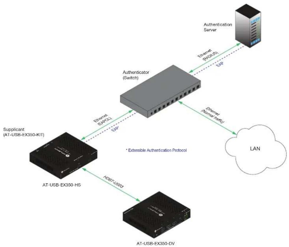
flowchart
graph TD
    A["AT-USB-EX350-KIT"] -->|Ethernet (EAPCL)| B["Authenticator (Switch)"]
    B -->|Ethernet (Normal traffic)| C["LAN"]
    D["AT-USB-EX350-HS"] -->|HSPPT-US93| E["AT-USB-EX350-DV"]
    F["Authentication Server"] -->|Ethernet (RADUS)| B
    style A fill:#f9f,stroke:#333
    style D fill:#f9f,stroke:#333
    style E fill:#f9f,stroke:#333
    style F fill:#ccf,stroke:#333
The following options are available:
| Protocol Description | |
| PEAP/MSCHAPv2 | Protected EAP; uses basic credentials in addition to a CA (certificate authority) certificate. |
| EAP-TLS | EAP Transport Layer Security; uses a client certificate, private key, private key password, and CA (certificate authority) certificate. |
Device Operation
- Log in to the web server.
- Click System in the side menu bar.
- Click Network in the top menu bar.
- Locate the IEEE 802.1x Authentication window group.
- Click the Enabled toggle button. When IEEE 802.1X is enabled, the toggle will be orange.
- Click the Authentication Method drop-down list and select the desired authentication method. In the example below, EAP-TLS is selected. Once a method is selected, the required fields for that method will be displayed. Enter the required information in each field.

- Click the SAVE button to commit changes.
Depending upon the authentication method, each field is described as follows:
- Username
The identifier for the user or device that is attempting to connect to the network.
- Password
Enter the password in this field.
- CA certificate
A digital certificate issued by a Certificate Authority (CA) that serves as the foundation of trust for verifying other certificates, such as client certificates and server certificates. To upload the certificate, click the Enabled button, above the Server Certificate field, then click the 📋 icon to select the certificate.
- Client Certificate
A digital certificate used to authenticate a device or user attempting to connect to the network. This is typically used in enterprise environments or when added security is desired. To upload the certificate, click the Enabled button, above the Server Certificate field, then click the 🔒 icon to select the certificate.

Device Operation
- Private Key
A component of the public key infrastructure (PKI) and associated with the digital certificate. This key is securely stored and used to prove identity and enable secure communication. Click the 🧑 icon to select the private key.
- Private Key Password
This password is designed as a level of security used to protect the private key, associated with a digital certificate. The password is masked by default. Click the 🔒 icon to toggle masking.
The table below provides a field summary. An orange dot indicates that this field will be displayed as part of the authentication method.
| Authentication Method | Username | Password | CA Certificate | Client Certificate | Private Key | Private Key Password |
| PEAP/MSCHAPv2 | ||||||
| EAP-TLS |
Device Operation
Setting the Host Name
By default, the AT-USB-EX350-KIT is assigned the following hostname: USB-EX350-[Last four digits of MAC address].
This value can be changed to easily identify the AT-USB-EX350-KIT within Velocity Device Manager or on a network. The hostname cannot exceed 15 characters in length.
- Log in to the web server.
- Click System in the side menu bar.
- Click Network in the top menu bar.
- Locate the Hostname window group.
- Click the Hostname field and enter the desired name.

- Click the icon to commit changes.

System Time
The AT-USB-EX350-KIT uses an internal clock to store the current date and time.
Setting the Time Zone
- Log in to the web server.
- Click System in the side menu bar.
- Click Time in the top menu bar.
-
Locate the Time Zone window group.
-
Click the 🐘 icon to display the list of time zones. Set the desired time zone by clicking it. Alternatively, the Filter field, within the drop-down list, can be used to filter various time zones from the list.

Device Operation
Assigning an NTP Server
If NTP is functioning correctly, then the date and time will be set automatically. The default server is pool.ntp.org.
- Log in to the web server.
- Click System in the side menu bar.
- Click Time in the top menu bar.
-
Locate the NTP window group.
-
Click the Enabled toggle switch to enable NTP. When enabled, the toggle switch will be orange.
-
Enter the NTP server name.
-
Click the icon to commit changes.

Device Operation
Setting the System Time
If an NTP server is not available, the system time can be set manually.
- Log in to the web server.
- Click System in the side menu bar.
-
Click Time in the top menu bar.
-
Locate the NTP window group and click the Enabled toggle button to disable NTP. When NTP is disabled, the toggle will be gray.

-
Locate the System Time window group.
-
Click the 📄icon open up the time settings.

Device Operation

- Click the correct date from the calendar widget. The currently set date will be highlighted in orange.
- Click on AM or PM and then select the correct hour from the clock widget, then click the correct minute from the next widget that is displayed.
Alternatively, the time and date can also be entered using the keyboard, within the System Time field.
USB Management
This section covers USB device power control and information on USB topology.
USB Configuration
The AT-USB-EX350-KIT provides three different device power modes for the USB VBUS +5V power supply, which is the standard power supply voltage provided through a USB connection to power devices or charge batteries. Three modes are provided for each USB DEVICES (5G) port: Follow USB Host, Always High, and Always Low.
- Log in to the web server.
- Click USB Management in the side menu bar.
- Click USB Configuration in the top menu bar.
- Click the Device Port [1...4] Vbus (5V) drop-down list to select the desired mode.

| Setting Description | |
| Follow USB Host | Allows the USB hub port to toggle on and off based on the presence of a USB host. |
| Always High | USB power is always enabled. For example, when connecting to a battery-powered speakerphone, selecting Always High ensures that the speakerphone continues to charge even when no USB host is connected. |
| Always Low | USB power is disabled on the port. |
Device Operation
USB Info
The AT-USB-EX350-KIT provides information about the USB port and the devices connected to them. This information is available via the web pages to provide visibility into the USB system.
- Log in to the web server.
- Click USB Management in the side menu bar.
- Click USB Info in the top menu bar.

Info
This section enables users to verify if the USB host and device ports are connected to devices and to monitor the total output current of the USB device ports.

Connected USB Resources
This section provides an overview of available USB resources.
Connected USB Resources
USB2.0

| Device Connections (max 7) | 2 |
| FS/LS In Endpoints (max 15) | 3 |
| FS/LS Out Endpoints (max 15) | 1 |
| HS In Endpoints (max 14) | 2 |
| HS Out Endpoints (max 15) | 1 |
USB3.0
The AT-USB-EX350-KIT supports up to 126 USB 3.0 endpoints, but cannot report the number of available USB 3.0 endpoints.
*Note, a USB device can have multiple In and Out endpoints. An In endpoint sends data to a USB Host, while an Out endpoint receives data from a USB Host.
USB 2.0:
• Displays the available USB 2.0 resources.
- Hover over the icon to view additional details:
• Device Connections: Indicates the number of USB 2.0 devices that can be connected. The maximum supported devices are 7.
- FS/LS/HS In/Out Endpoints: Displays the number of available Full Speed (FS), Low Speed (LS), and High Speed (HS) In/Out endpoints. The maximum supported endpoints are:
• FS/LS In/Out Endpoints: Up to 15.
• HS In Endpoints: Up to 14.
USB 3.0:
• The AT-USB-EX350-KIT supports up to 126 USB 3.0 endpoints.
USB devices can be connected based on the displayed availability. If the value is 0, then no additional USB devices can be connected.
Note:
- A single USB device may contain multiple In and Out endpoints:
- In endpoints send data to the USB host.
- Out endpoints receive data from the USB host.
USB 2.0 Speed Classifications:
• FS (Full Speed): Maximum transfer rate of 12 Mbps (keyboards / mouse devices).
• LS (Low Speed): Maximum transfer rate of 1.5 Mbps (audio interfaces and older USB peripherals).
• HS (High Speed): Maximum transfer rate of 480 Mbps (hard drives and cameras).
USB Topology
When a host device is connected to a USB HOST (5G) port, its USB topology is displayed in this section.
- If multiple USB devices are connected, hover over the hub tree name.
- When the cursor changes to a hand icon, click the hub name to view details about the connected USB devices.
USB Topology
HUB
[Port 3]:
[Port 4]:
USB2
Type
Hub
USB Address
9
USB Speed
High Speed
Vendor ID
05e3
Product ID
0610
- To get information on a specific device, click the click the desired port. In the example below, Port 1: Device (USB2) is selected.
USB Topology
HUB
← [Port 3]:
÷ [Port 4]:
USB2
Type
Device
USB Address
47
USB Speed
Full Speed
Vendor ID
1038
Product ID
12ec
RS-232 Control
RS-232 Control Settings
This section allows you to configure RS-232 parameters for controlling remote third-party devices through the RS-232 port. These settings also enable the port to function as a TCP proxy.
- Make sure that the third-party device is connected to the RS-232 port on the AT-USB-EX350-DV.
- Log in to the web server.
- Click Control in the side menu bar. The RS-232 Port field will show the model of the connected device endpoint.
- Click the Baud Rate drop down list to select the required baud rate. Available options are 9600, 19200, 38400, 57600, and 115200.
- Click the Parity, Data Bits, and Stop Bit drop-down lists to set the required value. In most cases, these values will be NONE, 8, and 1, respectively.
- To test the serial port settings, a serial command can be sent using the web pages. Enter the command in the Command field. The command can be in either ASCII or hexadecimal format. If the command is entered in hexadecimal format, click the HEX checkbox.

An example of an ASCII string might be: PWON.
A command in hexadecimal format might be:
\xBE\xEF\x03\x06\x00\xBA\xD2\x01\x00\x00\x60\x01\x00\x0D
- Click the SEND button to verify that the command works properly.
System Maintenance
Updating the Firmware
- Log in to the web server.
- Click Maintenance in the side menu bar.
- Click System in the top menu bar.

- Click the UPDATE button. Refer to Updating the Firmware (page 50) for more information on updating the firmware.
Performing a Factory Reset
The AT-USB-EX350-KIT can be restored to factory-default settings through the built-in web server or by pressing the RESET button on the rear panel. After performing a factory reset, the network IP mode will be set to DHCP mode and the login credentials will be reset. A new password will need to be created.
- Log in to the web server.
- Click Maintenance in the side menu bar.
- Click System in the top menu bar.
- Locate the Reset window group.
-
Click the FACTORY RESET button.
-
The Factory Reset confirmation dialog will be displayed.
-
Click FACTORY RESET to continue with the process or click CANCEL to abort.
-
Once the unit has finished rebooting, repeat the procedure for creating a password. Refer to Login Registration (page 14) for more information.

Device Operation
Rebooting the System
The following procedure will reboot the AT-USB-EX350-KIT. All network and other settings are preserved.
- Log in to the web server.
- Click System in the side menu bar.
- Click System in the top menu bar.
- Locate the Operation window group.
- Click the REBOOT button.

- The Reboot confirmation dialog box will be displayed.

- Click REBOOT to continue with the process or click CANCEL to abort.
- Once the unit has finished rebooting, the Login screen will be displayed.
Device Operation
Downloading Log Files
This feature allows log files to be downloaded to the local PC. Log files are used for troubleshooting purposes and may be requested by Atlona Technical Support Engineers.
- Log in to the web server.
-
Click Log in the top menu bar.
-
Click Maintenance in the side menu bar.
-
Under the Log Files window group, click the DOWNLOAD button. Log files are automatically downloaded to the C:\Users\ [Username]\Downloads folder on the PC.

Configuration and Management Interfaces
Web Server
The AT-USB-EX350-KIT includes a built-in web server. Atlona recommends that the web server be used to set up the AT-USB-EX350-KIT, as it provides intuitive management of all features. Refer to Logging in after Registration (page 15) for more information.
The AT-USB-EX350-KIT is shipped with DHCP enabled. Once connected to a network, the DHCP server will automatically assign an IP address to the unit. Use an IP scanner to determine the IP address of the AT-USB-EX350-KIT. If a DHCP server cannot be located within 15 seconds, the AT-USB-EX350-KIT will be placed in Automatic Private IP Addressing (APIPA) Mode (page 11). If a static IP address is desired, refer to Setting the IP Mode (page 18).
Login

Password
Enter the password in this field. The password will be masked when entering it in this field. To toggle between password masking and unmasking, click the icon.
LOGIN
Click this button to log in.
Configuration and Management Interfaces
System > System

Info
Model Name
The model number of this product.
Serial Number
The serial number of the AT-USB-EX350-KIT.
Firmware Version
The version of firmware that the AT-USB-EX350-KIT is running. Always make sure to check the AT-USB-EX350-KIT product page, on the Atlona web site, for the latest version of firmware.
IP Address
The IP address of the AT-USB-EX350-KIT.
MAC Address
The MAC address of the AT-USB-EX350-KIT.
Logins
Admin
If changing the login password, enter it in this field. Refer to Changing the Administrator Password (page 17) for more information.
Receiver Link
Indicates the link status between the host endpoint and the device endpoint. If it says Disconnected, then check the cabling between the host endpoint and the device endpoint.
Approximate Link Length
Displays the estimated length of the category cable between the AT-USB-EX350-KIT host endpoint and the device endpoint.
HDBT Temperature
Displays the temperature, in Celsius, of the AT-USB-EX350-KIT host endpoint (HS) and device endpoint (DV).
Configuration and Management Interfaces
System > Network

Network
MAC Address
The MAC address of the AT-USB-EX350-KIT.
Type
Click this drop-down list to select the IP mode of the AT-USB-EX350-KIT.
| Setting Description | |
| DHCP | Uses an available DHCP server to assign an IP address. |
| Static | Allows the IP address, subnet mask, and gateway IP address to be entered manually. |
IP
Enter the IP address of the AT-USB-EX350-KIT in this field. This field will only be available if Type is set to Static.
Netmask
Enter the subnet mask in this field. This field will only be available if Type is set to Static.
Gateway
Enter the gateway (router) address in this field. This field will only be available if Type is set to Static.
Hostname
Hostname
Enter the desired hostname in this field. Refer to Setting the Host Name (page 23) for more information.
Configuration and Management Interfaces
Control Protocol
Telnet Protocol (Port 23)
Click this toggle switch to enable or disable Telnet sessions. When enabled, the toggle switch will be orange. If disabled, then traffic on port 23 is forbidden.
SSH Protocol (Port 22)
Click this toggle switch to enable or disable SSH. When enabled, the toggle switch will be orange. If disabled, then traffic on port 22 is forbidden.
TCP Proxy (Port 9001)
Click this toggle switch to enable or disable TCP Proxy. When enabled, the toggle switch will be orange. If disabled, then traffic on port 22 is forbidden.
IEEE 802.1x Authentication
Refer to IEEE 802.1x Authentication (page 20) for more information.
Enabled
Click this toggle switch to enable or disable IEEE 802.1x authentication. When enabled, the toggle switch will be orange.
Authentication Method
Click this drop-down list to select the desired authentication method.
| Protocol Description | |
| PEAP/MSCHAPv2 | Protected EAP; uses basic credentials in addition to a CA (certificate authority) certificate. |
| EAP-TLS | EAP Transport Layer Security; uses a client certificate, private key, private key password, and CA (certificate authority) certificate. |
The following fields are available, depending on the authentication method that is selected:
Username
The identifier for the user or device that is attempting to connect to the network.
Password
Enter the password in this field.
CA certificate
A digital certificate issued by a Certificate Authority (CA) that serves as the foundation of trust for verifying other certificates, such as client certificates and server certificates. To upload the certificate, click the Enabled button, above the Server Certificate field, then click the 📋 icon to select the certificate.
Client Certificate
A digital certificate used to authenticate a device or user attempting to connect to the network. This is typically used in enterprise environments or when added security is desired. To upload the certificate, click the Enabled button, above the Server Certificate field, then click the 🔊 icon to select the certificate.
Private Key
A component of the public key infrastructure (PKI) and associated with the digital certificate. This key is securely stored and used to prove identity and enable secure communication. Click the ➕ icon to select and upload the private key.
Private Key Password
This password is designed as a level of security used to protect the private key, associated with a digital certificate. The password is masked by default. Click the icon to toggle masking.
SAVE
Click this button to commit changes.
Configuration and Management Interfaces
System > Time

Time Zone
Click the ... icon to set the time zone. Refer to Setting the Time Zone (page 24) for more information.
NTP
NTP Hostname
Enter the NTP server name in this field. The default server is pool.ntp.org.
System Time
Click the 📁 icon to set the system time. Refer to Setting the System Time (page 26) for more information.
Configuration and Management Interfaces
USB Management > USB Configuration

USB Device Power Control
Device Port [1...4] Vbus (5V)
Click the drop-down list to select the desired Vbus mode.
| Setting Description | |
| Follow USB Host | Allows the USB hub port to toggle on and off based on the presence of a USB host connected to the host endpoint. |
| Always High | USB power is always enabled. For example, when connecting to a battery-powered speakerphone, selecting Always High ensures that the speakerphone continues to charge even when no USB host is connected.![Atlona AT-USB-EX350-KIT - Device Port [1...4] Vbus (5V) - 1](/content/2026/05/1045934/images/c21c2e20f4c43519eec3f3acada9d0ce1c94fecdda803cc836e298fb6fc82bb8.jpg) NOTE: Vbus will toggle high-low-high in this mode when a USB host is connected to the host endpoint to ensure proper enumeration of the USB device. NOTE: Vbus will toggle high-low-high in this mode when a USB host is connected to the host endpoint to ensure proper enumeration of the USB device. |
| Always Low | USB power is disabled on the port. |
Configuration and Management Interfaces
USB Management > USB Info
![ATLONA System USB Management Control Maintenance USB Management USB Configuration USB Info Info USB Host Status Connected USB Device Status USB Device Port 1 Connected USB Device Port 2 Connected USB Device Port 3 Disconnected USB Device Port 4 Disconnected Total USB Device Current (mA) < 100 USB Topology USB2 ~ [Port 1] Device (USB2) ~ [Port 2] Device (USB2) ~ [Port 3] ~ [Port 4] Connected USB Resources USB2.0 Device Connections (max 7) 2 FSLS In Endpoints (max 15) 3 FSLS Out Endpoints (max 15) 1 HS In Endpoints (max 14) 2 HS Out Endpoints (max 15) 1 USB3.0 The AT-USB-EXCOS-IGT supports up to 126 USB 3.0 endpoints, but cannot report the number of available USB 3.0 endpoints. *Note, a USB device can have multiple in and Out endpoints. An In endpoint sends data to a USB Host, while an Out endpoint receives data from a USB Host](/content/2026/05/1045934/images/da7b32ce6de2589811afafc48cc277bed35d4ae79b908a7d0ab94f4cbd8ea42b.jpg)
Info
Refer to USB Info (page 29) for more information.
USB Host Status
If the host device is connected to the USB HOST (5G) port on the AT-USB-EX350-KIT Host Endpoint, this field will display Connected.
USB Device Status
The USB Device Port [1...4] fields indicate whether a USB device is connected to the corresponding port. If a device is properly connected, the field will display Connected.
Total USB Device Current (mA)
Displays the total current in milliamperes consumed by the connected USB devices.
Configuration and Management Interfaces
Connected USB Resources
USB 2.0
The Valens chipset used in the USB-EX350-KIT limits the number of USB 2.0 devices and endpoints that are supported by the link. This section provides information on connected USB 2.0 resources to help users understand the available resources based on already connected devices.. Each USB device contains multiple input and output endpoints. The “In” endpoint transmits data to the USB host, while the “Out” endpoint receives data from the USB host.

DEFINITIONS
In Endpoint - Sends data to a USB host.
Out Endpoint – Receives data from a USB host.
LS - Low Speed (1.5 Mbps); used by keyboards / mouse devices.
FS - Fast Speed (12 Mbps); used by audio interfaces and older USB peripherals.
HS - High Speed (480 Mbps); used by hard drives and cameras.
• Device Connections (max 7)
Displays the number of USB 2.0 devices connected to the AT-USB-EX350-KIT. A maximum of seven USB devices are supported.
• FS/LS In Endpoints (max 15)
Displays the number of full-speed (FS) and low-speed (LS) "In" endpoints that are connected to the AT-USB-EX350-KIT. A maximum of 15 "In" endpoints are supported.
• FS/LS Out Endpoints (max 15)
Displays the number of full-speed (FS) and low-speed (LS) "Out" endpoints that are connected to the AT-USB-EX350-KIT. A maximum of 15 "Out" endpoints are supported.
• HS In Endpoints (max 14)
Displays the number of high-speed (HS) "In" endpoints that are connected to the AT-USB-EX350-KIT. A maximum of 14 "In" endpoints are supported.
• HS Out Endpoints (max 15)
Displays the number of high-speed (HS) "Out" endpoints that are connected to the AT-USB-EX350-KIT. A maximum of 15 "Out" endpoints are supported.
USB 3.0
The Valens chipset has a different USB implementation for USB 3.0 which does not impose any limitations beyond the USB standard. Due to the nature of this implementation, the AT-USB-EX350-KIT supports up to 126 USB 3.0 endpoints, but cannot report the number of available USB 3.0 endpoints.
Configuration and Management Interfaces
USB Topology
When the AT-USB-EX350-KIT is connected to a host device, the USB topology will be displayed. When a device is connected directly to the AT-USB-EX350-KIT, information about that device will be shown. When a hub is connected to a device port, information about the hub will be provided, but the web UI will not be able to provide information about devices connected to that hub. Refer to USB Info (page 29) for more information.
USB Topology
HUB
[Port 3]:
[Port 4]:
USB2
Type Hub
USB Address 9
USB Speed High Speed
Vendor ID 05e3
Product ID 0610
Configuration and Management Interfaces
Control

RS-232
RS-232 Port
The name of the endpoint that includes the RS-232 port. This field cannot be changed.
Baud Rate
Click this drop-down list to select the data transmission rate in bit-per-second (bps). Available options are 9600, 19200, 38400, 57600, or 115200.
Parity
Click this drop-down list to select the parity bit value. The parity bit helps detect single-bit errors in data transmission. The parity bit cannot correct errors. However, if an error does occur, the receiver can then request that the data be retransmitted.
| Setting Description | |
| NONE | No parity (error checking) is applied. |
| ODD | The parity bit is set so that the total number of 1 bits in the data, including the parity bit, is odd. For example, 10110011 contains five 1 bits, which is an odd value. Applying ODD parity, the parity bit is set to 0 and the data becomes 101100110, maintaining an odd number of 1 bits in the data. |
| EVEN | The parity bit is set so that the total number of 1 bits in the data, including the parity bit, is even. For example, 10110011 contains five 1 bits, which is an odd value. Applying EVEN parity, the parity bit is set to 1 and the data becomes 101100111, maintaining an even value of 1 bits in the data. |
Data Bits
Click this drop-down list to select the number of data bits in each packet. Typically, packets are sent in bytes (8 bits). However, some older systems may use 7-bit data. Available options are 7 or 8.
Stop Bits
Click this drop-down list to select the number of stop bits. Stop bits are used to signal the end of a data frame. A value of 1 is standard. Available options are 1 or 2.
Configuration and Management Interfaces
Command
Enter the command in the Command field. The command can be in either ASCII or hexadecimal format. If the command is entered in hexadecimal format, click the HEX checkbox.
SEND
Click the SEND button to verify that the command works properly.
Configuration and Management Interfaces
Maintenance > System

Firmware
Model
The model of this product.
Firmware Version
The version of firmware that the AT-USB-EX350-KIT is running. Always make sure to check the AT-USB-EX350-KIT product page, on the Atlona web site, for the latest version of firmware.
MAC Address
The MAC address of the AT-USB-EX350-KIT.
IP Address
The IP address of the AT-USB-EX350-KIT.
Host Firmware
ARM Version
The version of firmware used by the ARM processor.
HDBT Version
The version of HDBaseT ^® firmware.
Device Firmware Reset
MCU Version
The version of firmware used by the microcontroller in the device endpoint.
HDBT Version
The version of HDBaseT ^® firmware.
Reset to Default
Click the FACTORY RESET button to reset the AT-USB-EX350-KIT to factor-default settings.
System Reboot
Click the REBOOT button to reboot the AT-USB-EX350-KIT. All settings will be preserved.
Configuration and Management Interfaces
Maintenance > Log
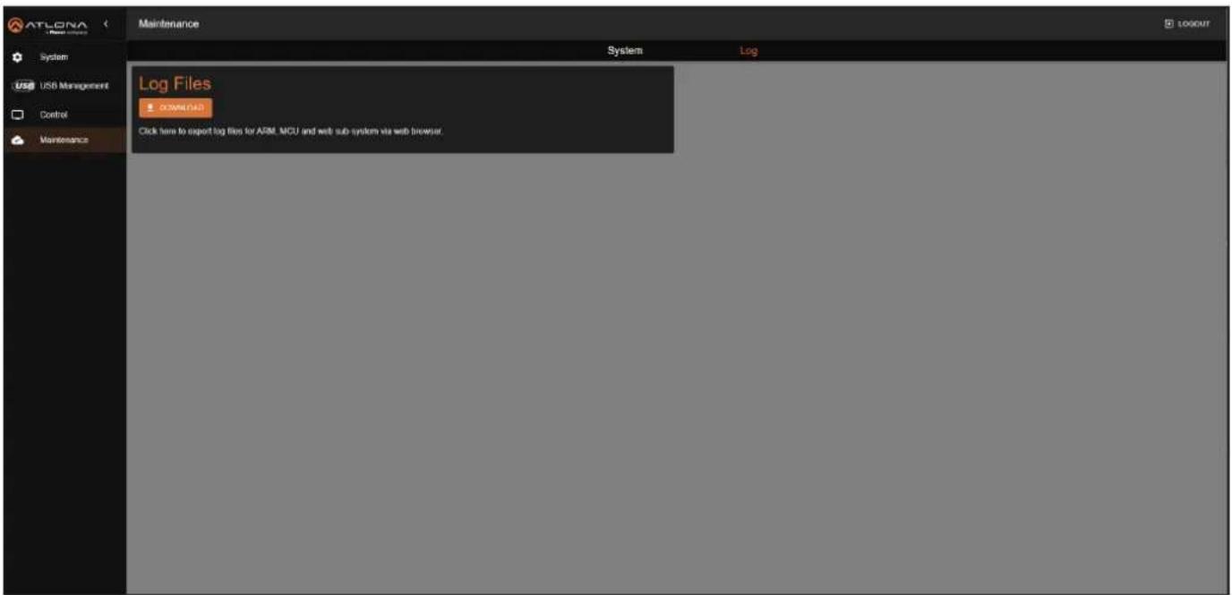
Log Files
DOWNLOAD
Click this button to download log files to the C:\Users\ [Username]\Downloads folder on the PC. Log files are used for troubleshooting purposes and may be requested by Atlona Technical Support Engineers.
Appendix
Mounting Instructions
The AT-USB-EX350-KIT includes mounting brackets, which can be used to attach the units to any flat surface. Use the included screws to attach the mounting brackets.
-
Locate the included screws in the packaging.
-
Align the mounting bracket with the enclosure, matching the holes on the side of the enclosure with those on the bracket, as shown below.

natural_image
Technical line drawing of a computer case with ventilation slots, mounting bracket, and screw base (no text or symbols)-
Secure the bracket using a small Phillips screwdriver and a screw.
-
Repeat steps 2 and 3 for the other mounting bracket.
- If using a drywall surface, a #6 drywall screw is recommended.
- Attach the unit to a flat surface using the oval-shaped holes on each bracket.
Updating the Firmware
Updating the firmware can be performed using the built-in web server or over USB.
Updating using the Web Server
Requirements:
- AT-USB-EX350-KIT
-
Firmware file
• Computer on the same network as the AT-USB-EX350-KIT -
Download the firmware file from the Firmware tab on the AT-USB-EX350-KIT product page. Then, extract the contents of the .zip file to a folder on your computer's desktop.
- Power on the unit and connect an Ethernet cable from the computer, containing the firmware, to the same network where the AT-USB-EX350-KIT connected.
- Login to the web server.
- Click Maintenance in the side menu bar.
- Click System in the top menu bar.
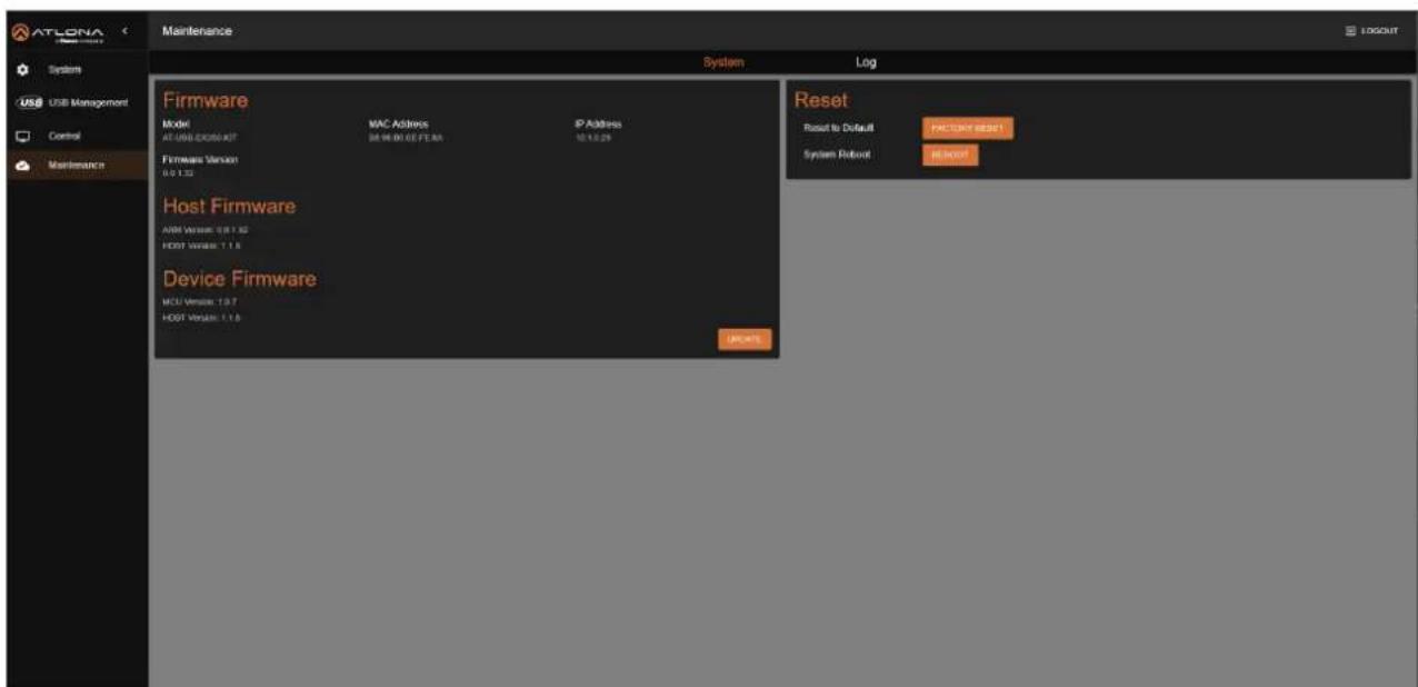
- The firmware version information for both the host (AT-USB-EX350-HS) and the device (AT-USB-EX350-DV) will be displayed.
- Click the UPDATE button.
- The Open dialog will be displayed. Locate the firmware file and click the Open button
Appendix
- After the firmware is uploaded to the AT-USB-EX350-KIT, the following screen will be displayed. Note that other screens will be displayed during the firmware update process.

IMPORTANT: The firmware update process may take several minutes. Do not disconnect power from the AT-USB-EX350-KIT during the update process.

Please do not power off the device during upgrade
- Once the update process is complete, the AT-USB-EX350-KIT will automatically reboot and the Login screen will be displayed.
Appendix
Updating over USB
Requirements:
- AT-USB-EX350-KIT
- USB-C cable
-
Firmware file
-
Download the firmware file from the Firmware tab on the AT-USB-EX350-KIT product page. Then, extract the contents of the .zip file to a folder on your computer's desktop.
-
Power on the AT-USB-EX350-KIT.
-
Connect a USB-C cable from the MGMT port on the AT-USB-EX350-KIT (Host Endpoint) to the computer with the firmware file.
-
Press and hold the IP MODE button on the front panel of the Host Endpoint for approximately 3 seconds, then release.
-
The "USB UPDATE" folder will be displayed on the PC. If the folder does not open automatically, locate and open it through Windows Explorer.
-
Drag and drop the firmware file to the drive, then disconnect the USB cable from the PC.
-
Wait 15 seconds. The PWR LED will begin to flash when the update process begins.

IMPORTANT: The firmware update process may take a few minutes. Do not disconnect power from the AT-USB-EX350-KIT during the update process.
-
Once the firmware update has completed, the USB-EX350-KIT will automatically reboot. The PWR LED will be off during this time.
-
Once the PWR LED returns to solid green, verify that the firmware version has been updated.
Specifications
| USB Capabilities | |
| Protocol Support | USB 2.0, USB 3.2 Gen 1 (5 Gbps) |
| USB 2.0 Capabilities^(1) | Maximum hubs: 9Maximum hub tiers: 5 (including the one in the AT-USB-EX350-KIT)Maximum devices: 7Maximum endpoints: 14 (IN), 15 (OUT) |
| USB 3.2 Gen 1 Capabilities^(1) | Maximum hub tiers: 5 (including the one in the AT-USB-EX350-KIT)Maximum end points: 126 |
| USB Transfer Types | Control, Bulk, Interrupt, Isochronous |
| Internal Hubs | USB 2.0: 1 Hub, 1 TierUSB 3.2 Gen 1: 2 Hubs, 2 Tiers |
| USB Power | Host: No PowerDevice: max 1.5A per port, 3.2A total across all device ports |
| USB Device VBUS Control | Per-port settings: Follow USB Host, Always High, Always Low |
| Bandwidth^(2) | USB 2.0: 480 MbpsUSB 3.2 Gen 1: 5 Gbps |
| Ethernet | |
| Port 1 x RJ45 on Host Endpoint | |
| Standards and Protocols HTTP | HTTPS, Telnet, SSH, JSON over WebSockets, TCP Proxy for RS-232, NTP |
| Speeds 10/100 Mbps | |
| Addressing DHCP, Static – selectable through built-in web server and API commands | |
| 802.1x Support PEAP-MSCHAPv2, EAP-TLS | |
| RS-232 | |
| Port 1 x 3-pin captive screw on Use External device control via Baud Rates 9600, 19200, 38400, Data Flow Bidirectional | Device EndpointTCP Proxy, 57600, 115200 |
| Distance Feet Meters | ||
| CAT 6a U/FTP - straight run 330 | 100 | |
| CAT 6a U/FTP - through patch panel/coupler | 295 90 | |
| CAT 6a UTP - either straight run or through patch panel/ coupler | 230 70 | |
| CAT 5e UTP - either straight run or through patch panel/ coupler | 164 50 | |
| Indicators | |
| Host Endpoint | |
| PWR | 1 x LED, green |
| LINK | 1 x LED, green |
| FW^(3) | 1 x LED, amber |
| Device Endpoint | |
| PWR | 1 x LED, green |
| LINK | 1 x LED, green |
| FW^(3) | 1 x LED, amber |
Appendix
| Connectors (Host Endpoint) | |
| USB HOST (5G) 1 x USB-C, locking | |
| MGMT 1 x USB-C | |
| LAN 1 x RJ45 | |
| HDBT-USB3 1 x RJ45 | |
| 48V - 1.36A(4) | 1 x 2-pin captive screw |
| Connectors (Device Endpoint) | |
| USB DEVICES (5G) 3 x USB-A | 1 x USB-C, locking |
| DEBUG 1 x USB-C | |
| RS-232 1 x 3-pin captive screw | |
| HDBT-USB3 1 x RJ45 | |
| 48V - 1.36A(4) | 1 x 2-pin captive screw |
| Environmental Fahrenheit Celsius | |
| Operating Temperature +32 to +104 0 to +40 | |
| Storage Temperature -4 to +158 -20 to +70 | |
| Operating Humidity (RH) 20% to 90%, non-condensing | |
| Power | Powered from | Total System Power | Host Endpoint | Device Endpoint |
| Consumption (system under full USB device load) | Host Endpoint | 33 W (max.) | 25.4 BTU/h | 21 BTU/h |
| Device Endpoint | 29 W (max.) | 11.1 BTU/h | 25 BTU/h | |
| External Power Supply | Input: 100 - 240 V AC, 50/60 HzOutput: 48 V DC / 1.36 A | |||
| Dimensions (H x W x D) | Inches | Millimeters |
| Host Endpoint | 0.91 x 5.31 x 3.94 23 x 135 x 100 | |
| Device Endpoint | 0.91 x 5.31 x 3.94 23 x 135 x 100 |
| Weight | Pounds | Kilograms |
| Host Endpoint | 0.68 | 0.31 |
| Device Endpoint | 0.71 | 0.32 |
| Certification | ||
| Extender Kit | CE, FCC, UKCA, RCM | |
| Power Supply | CE, FCC, UKCA, RCM, UL | |
| Compliance | ||
| NDAA-889 | Yes | |
| Warranty | ||
| 3 years | View the full warranty information here:https://atlona.com/warranty | |
Refer to footnotes on the next page.
Appendix
Footnotes
(1) A USB device can have multiple In and Out endpoints. An In endpoint sends data to a USB Host, while an Out endpoint receives data from a USB Host.
(2) Specified bandwidth is the total available bandwidth. Actual bandwidth available for payload data will be reduced by USB and transport overhead. Practical payload data rates will be approximately 320 Mbps for USB 2.0 and 3.8 Gbps for USB 3.0.
(3) Kit can be powered from either end.
(4) Used to indicate the state of the HDBT-USB3 firmware.
- Sales, Marketing, and Customer Support
- Operating Notes
- Warranty
- Safety and Certification
- CAUTION
- FCC Compliance
- Copyright, Trademark, and Registration
- Table of Contents
- Introduction
- Features
- Package Contents
- Panel Description
- PWR
- USB HOST (5G)
- MGMT
- LAN
- IP MODE
- - Firmware Update Mode
- - IP Mode
- - Factory Reset
- HDBT-USB3
- 48V / 1.36A
- USB DEVICES (5G)
- RS-232
- 48V / 1.36A
- HDBT-USB3
- DEBUG
- Installation
- Connection Instructions
- IP Configuration
- Automatic Private IP Addressing (APIPA) Mode
- Device Operation
- LED Indicators
- RS-232 Control
- Logging in to the Web Server
- Login Registration
- Logging in after Registration
- System Settings
- Obtaining System Information
- Changing the Administrator Password
- Network Configuration
- Setting the IP Mode
- Static IP Mode
- DHCP Mode
- IEEE 802.1x Authentication
- - Private Key
- - Private Key Password
- Setting the Host Name
- System Time
- Setting the Time Zone
- Assigning an NTP Server
- Setting the System Time
- USB Management
- USB Configuration
- USB Info
- Info
- Connected USB Resources
- USB 2.0:
- USB 3.0:
- Note:
- USB 2.0 Speed Classifications:
- USB Topology
- RS-232 Control Settings
- System Maintenance
- Updating the Firmware
- Performing a Factory Reset
- Rebooting the System
- Downloading Log Files
- Configuration and Management Interfaces
- Web Server
- Password
- LOGIN
- Model Name
- Serial Number
- Firmware Version
- IP Address
- MAC Address
- Logins
- Admin
- Receiver Link
- Approximate Link Length
- HDBT Temperature
- Network
- Type
- IP
- Netmask
- Gateway
- Hostname
- Control Protocol
- Telnet Protocol (Port 23)
- SSH Protocol (Port 22)
- TCP Proxy (Port 9001)
- Enabled
- Authentication Method
- Username
- CA certificate
- Client Certificate
- Private Key
- Private Key Password
- SAVE
- Time Zone
- NTP
- NTP Hostname
- USB Device Power Control
- Device Port [1...4] Vbus (5V)
- USB Host Status
- USB Device Status
- Total USB Device Current (mA)
- USB 2.0
- DEFINITIONS
- • Device Connections (max 7)
- • FS/LS In Endpoints (max 15)
- • FS/LS Out Endpoints (max 15)
- • HS In Endpoints (max 14)
- • HS Out Endpoints (max 15)
- USB 3.0
- RS-232
- RS-232 Port
- Baud Rate
- Parity
- Data Bits
- Stop Bits
- Command
- SEND
- Firmware
- Model
- Host Firmware
- ARM Version
- HDBT Version
- Device Firmware Reset
- MCU Version
- Reset to Default
- System Reboot
- Log Files
- DOWNLOAD
- Appendix
- Mounting Instructions
- Updating using the Web Server
- Updating over USB
- Footnotes
Brand : Atlona
Model : AT-USB-EX350-KIT
Category : Extendeur de données