
INT 8801 - TV Stand Vogel's - Free user manual and instructions
Find the device manual for free INT 8801 Vogel's in PDF.


| Product Type | TV Stand |
| Brand | Vogel's |
| Model | INT 8801 |
| Dimensions (W x H x D) | 1400 x 600 x 400 mm |
| Weight | 25 kg |
| Maximum TV Size | 65 inches |
| Maximum Load Capacity | 50 kg |
| Material | Tempered glass and metal |
| Color | Black |
| Shelf Configuration | 2 adjustable shelves |
| VESA Compatibility | Not applicable (stand alone) |
| Cable Management | Yes, integrated cable channels |
| Assembly Required | Yes |
| Power Supply | Not required (furniture) |
| Cleaning Instructions | Wipe with a soft dry cloth; avoid abrasive cleaners |
| Safety Features | Anti-tip strap included |
| Spare Parts | Contact Vogel's customer service |
| Warranty | 2 years |
| Country of Origin | Netherlands |
Frequently Asked Questions - INT 8801 Vogel's
User questions about INT 8801 Vogel's
0 question about this device. Answer the ones you know or ask your own.
Ask a new question about this device
Download the instructions for your TV Stand in PDF format for free! Find your manual INT 8801 - Vogel's and take your electronic device back in hand. On this page are published all the documents necessary for the use of your device. INT 8801 by Vogel's.
USER MANUAL INT 8801 Vogel's
natural_image
Two parallel gray structural beams with mounting holes against an orange background (no text or symbols)
natural_image
Two parallel black structural beams with small vehicle icons at joints (no text or symbols)Installation Manual
EN Product manual
DE Produkthandbuch
| Pre | information | 3 |
| Mounting | Instructions | 9 |
| Notes | 29 | |
| Contact | Details | 32 |

ADJUSTING THE WALL BRACKETS PLA 9302
SET HEIGHT (max 10 mm) SET DISTANCE TO THE WALL
min. 40 mm
max. 80 mm


SET WIDTH FIX


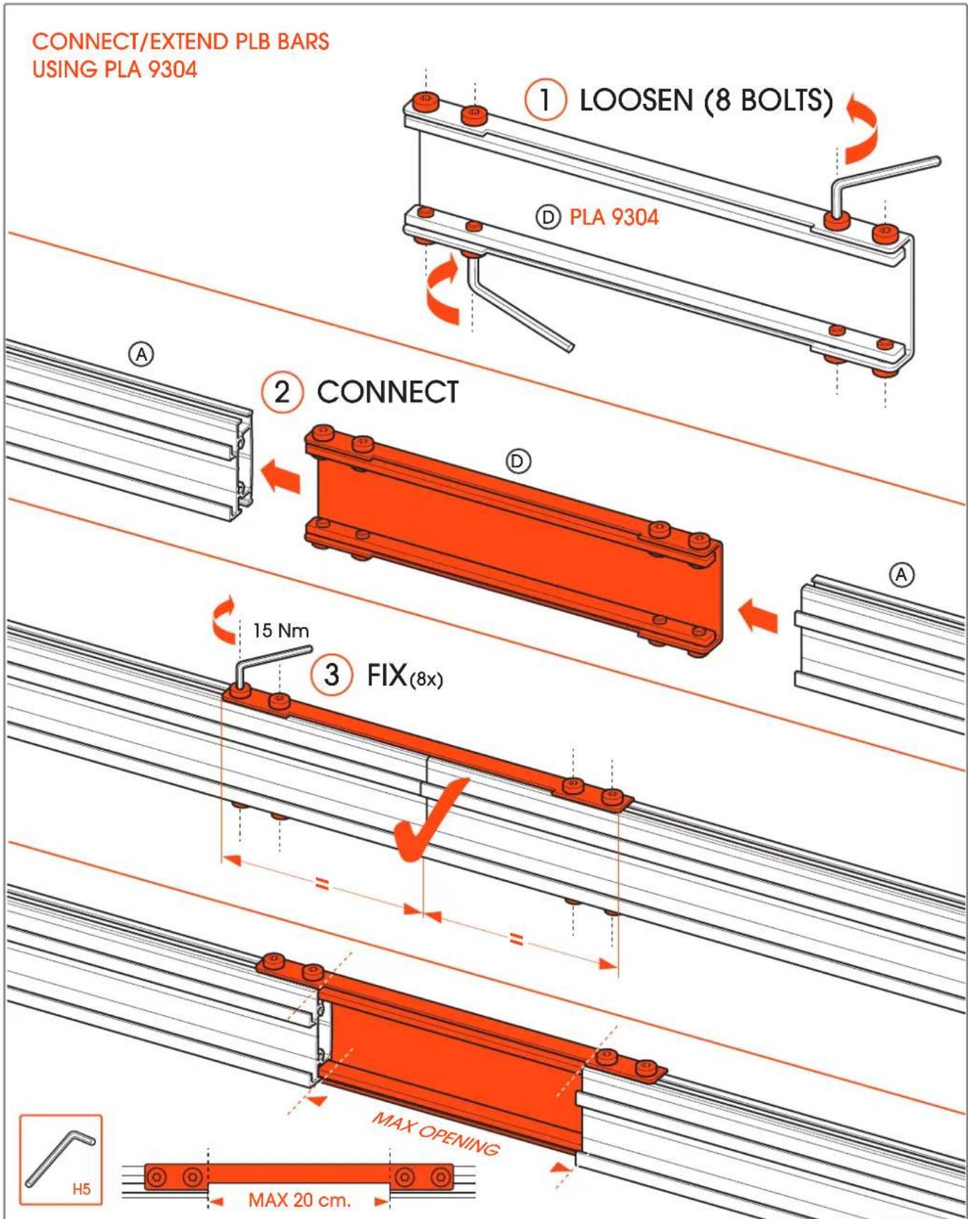
www.vogels.com
INSTALL EXTENSION PIECES (OPTIONAL PLA 9303)
left and/or right

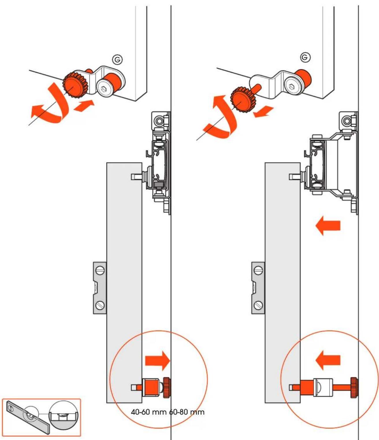
MOUNTING ADJUSTABLE FEET FOR WALL SOLUTION
explanation options PLA 9307
www.vogels.com
OPTIONAL PLA 9306
set spacer (1)

X1-X2-X3
SEE ASSEMBLY STEPS

set spacer (2)
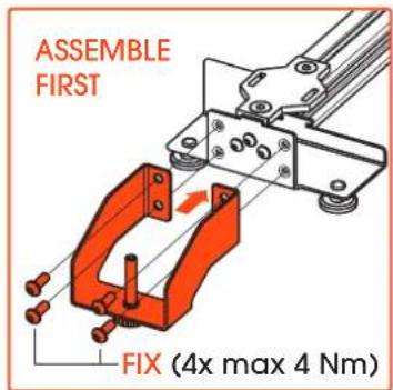


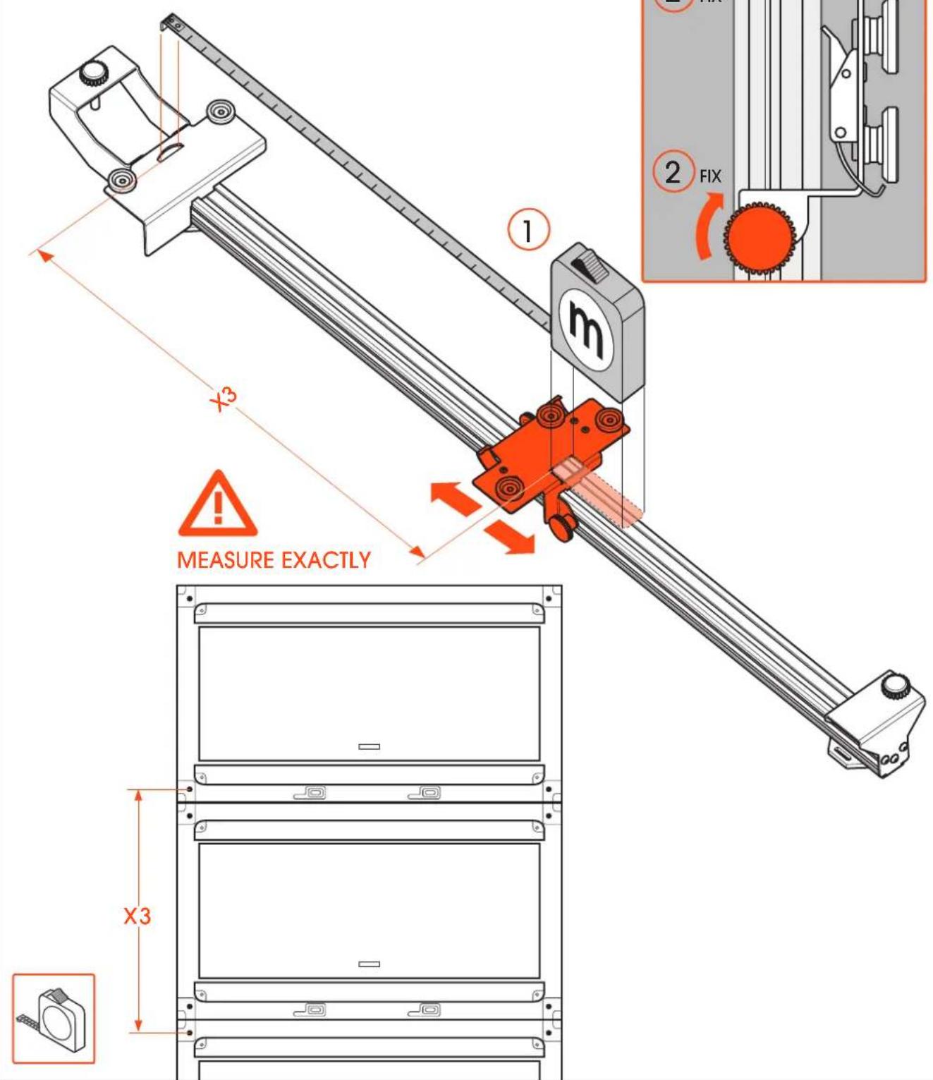
MEASURE EXACTLY

E2x

www.vogels.com
1a
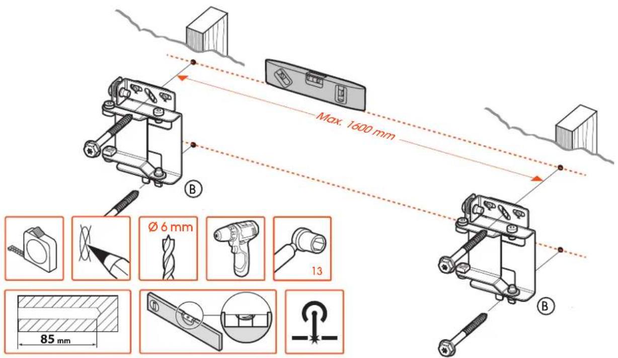
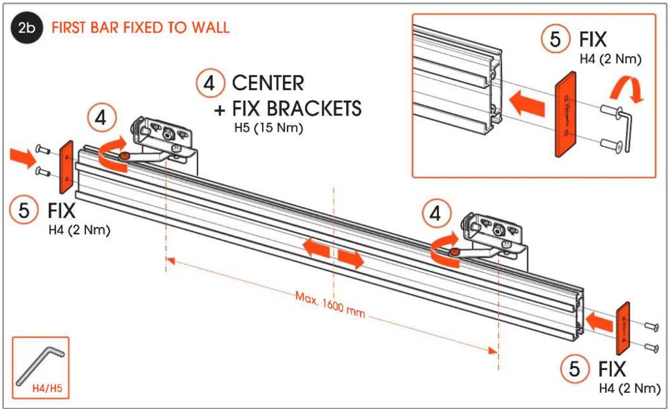
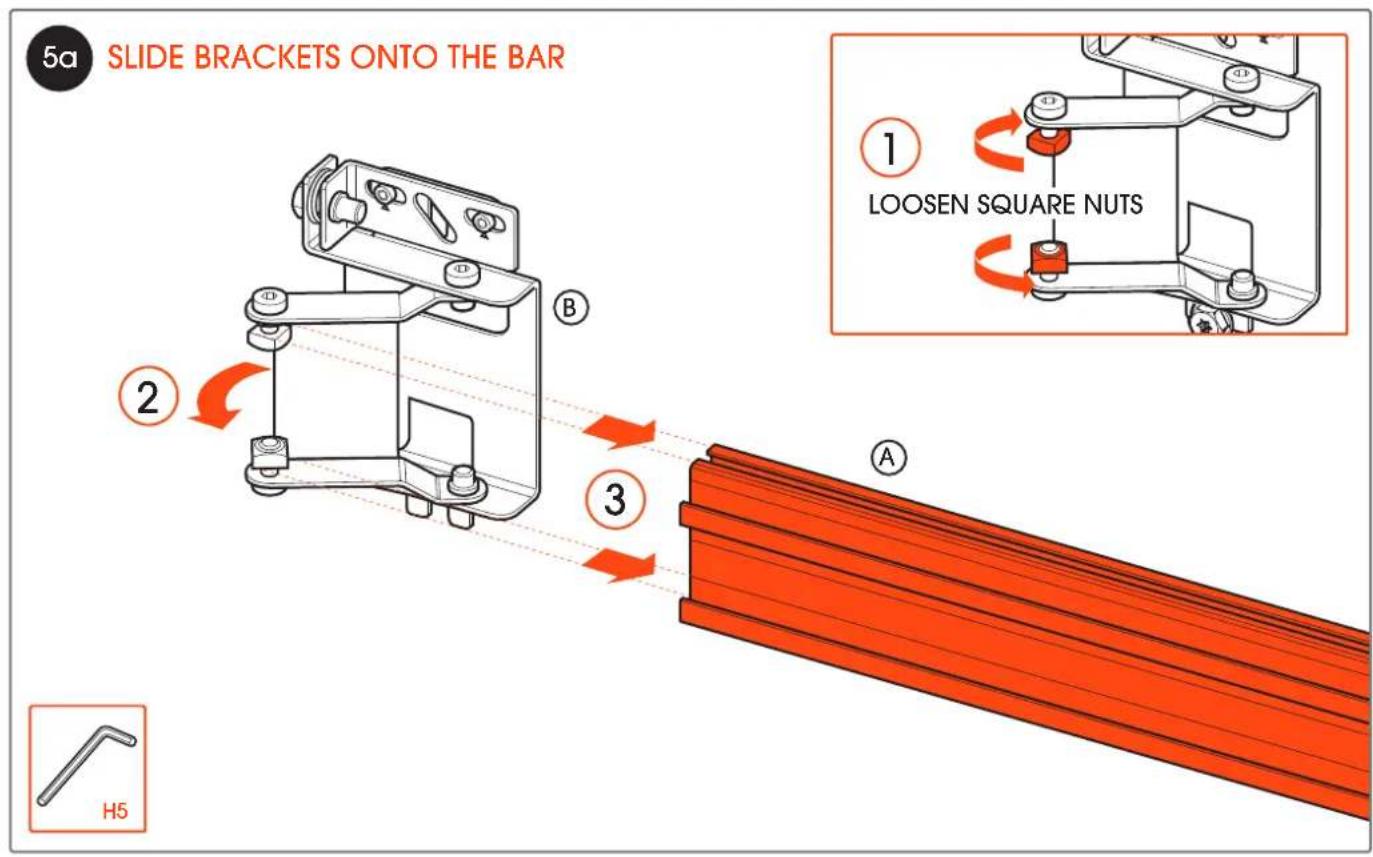
INSTALL WALL BRACKETS
Maximum distance between two brackets is 1600mm
1b

www.vogels.com

www.vogels.com
3a
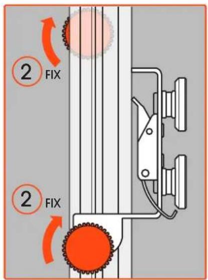
INSTALL SECOND BAR

www.vogels.com


www.vogels.com
3d
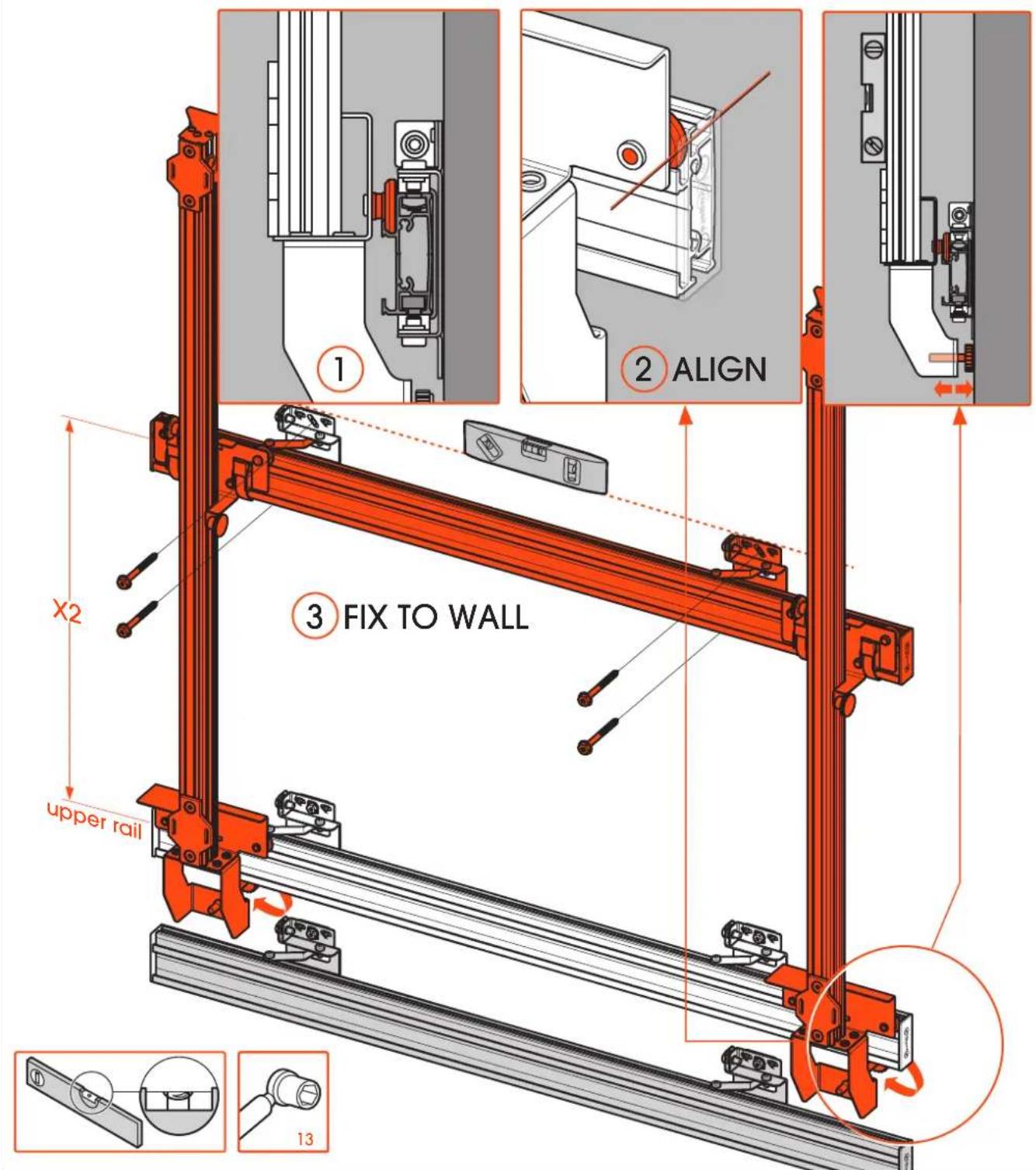
INSTALL SECOND BAR USING SPACERS (STEP-1)
set distance X1 of the spacers check project drawing (supplied by Vogels)

www.vogels.com

www.vogels.com
3f INSTALL SECOND BAR USING SPACERS (STEP-3)
place spacers (+ second bar) in lower rail of the first bar and mount second bar


4a
INSTALL THIRD + BARS

www.vogels.com


www.vogels.com
4d
INSTALL THIRD + BARS USING SPACERS (STEP-1)
set distance X2 of the spacers
check project drawing (supplied by Vogels)

www.vogels.com

www.vogels.com
4f
INSTALL THIRD + BARS USING SPACERS (STEP-3)
Place spacers with the bar to be mounted in the upper rail of the last mounted bar

www.vogels.com

www.vogels.com
5c
INSTALL TOP BAR USING SPACERS (STEP-1)
set distance X3 of the spacers check project drawing (supplied by Vogels)
www.vogels.com

www.vogels.com

www.vogels.com
6a
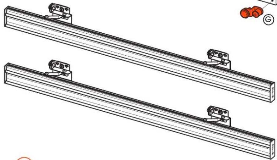
INSTALL CABINETS (STEP-1)
first connect 4 cabinets (2x2)* and hang them left in the lower two bars

natural_image
Technical line drawing of a mechanical assembly with mounting brackets and housing (no text or symbols)
natural_image
Technical line drawing of two parallel metal beams with mounting brackets and red components, no text or symbols present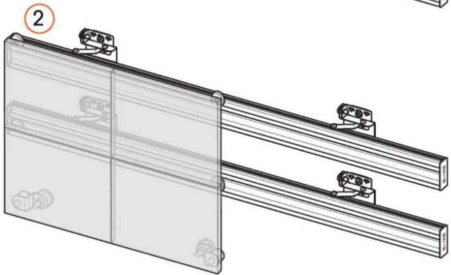
natural_image
Technical line drawing of a mechanical assembly with two parallel plates and mounting brackets (no text or symbols)*Connect dvLED cabinets according to dvLED brand description
6b
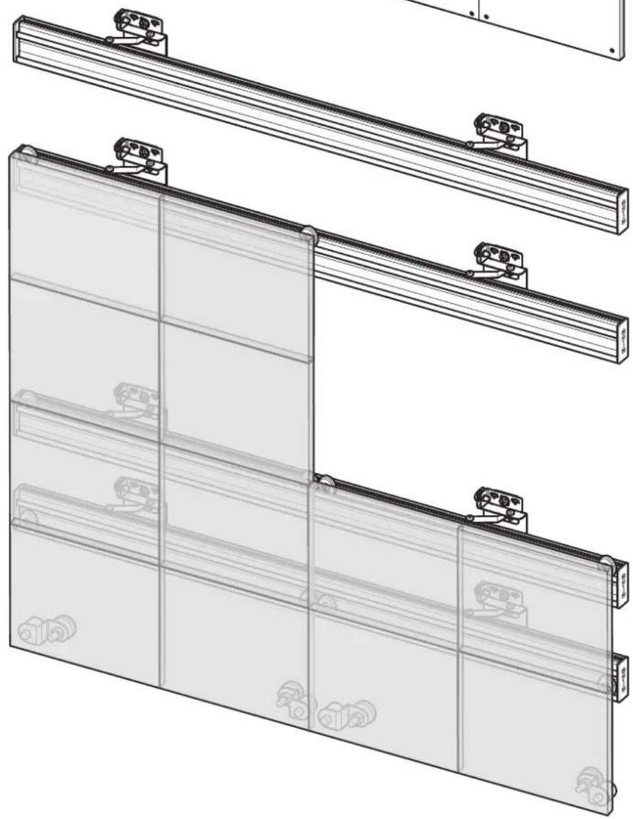
INSTALL CABINETS (STEP-2)
after installing the first row of cabinets start hanging the second row

natural_image
Technical line drawing of a mechanical assembly with mounting brackets and housing (no text or symbols)
natural_image
Technical line drawing of a modular panel assembly with mounting brackets and mounting fixtures (no text or symbols)www.vogels.com
6c
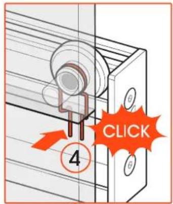
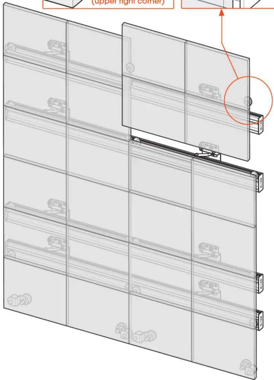
INSTALL CABINETS (STEP-3)
top row

natural_image
Technical line drawing of a mechanical assembly with mounting brackets and housing (no text or symbols)
www.vogels.com
Vogel's Products BV
HONDSRUGLAAN 93,
5628 DB EINDHOVEN,
THE NETHERLANDS
T +31 (0)40 264 74 00
E info@vogels.com
W www.vogels.com
(GB) Subjed to printing errors and technical amendments.
Designed and engineered in the Netherlands. More information on: www.vogels.com
VOGEL'S PRODUCTS BV, HONDSRUGLAAN 93, 5628 DB EINDHOVEN, THE NETHERLANDS


- Installation Manual
- ADJUSTING THE WALL BRACKETS PLA 9302
- MOUNTING ADJUSTABLE FEET FOR WALL SOLUTION
- 1a
- INSTALL WALL BRACKETS
- 1b
- 3d
- INSTALL SECOND BAR USING SPACERS (STEP-1)
- 3f INSTALL SECOND BAR USING SPACERS (STEP-3)
- 4d
- INSTALL THIRD + BARS USING SPACERS (STEP-1)
- 4f
- INSTALL THIRD + BARS USING SPACERS (STEP-3)
- 5c
- INSTALL TOP BAR USING SPACERS (STEP-1)
- 6a
- INSTALL CABINETS (STEP-1)
- 6b
- INSTALL CABINETS (STEP-2)
Brand : Vogel's
Model : INT 8801
Category : TV Stand