TR-30BEV-L-SG-C - Wine cellar True - Free user manual and instructions
Find the device manual for free TR-30BEV-L-SG-C True in PDF.


| Brand | True |
| Model | TR-30BEV-L-SG-C |
| Product Type | Wine Cellar |
| Capacity | 30 bottles (approx.) |
| Dimensions (H x W x D) | 34.5 x 24 x 24 in (87.6 x 61 x 61 cm) |
| Weight | 85 lbs (38.6 kg) |
| Power Supply | 120 V / 60 Hz |
| Temperature Range | 41°F – 64°F (5°C – 18°C) |
| Cooling System | Compressor-based, vibration-free |
| Interior Light | LED, automatic on door open |
| Shelving | Chrome wire shelves, slide-out |
| Door Type | Solid panel, reversible hinge |
| Installation | Freestanding, requires ventilation clearance |
| Maintenance | Clean condenser coils every 6 months; wipe interior with damp cloth |
| Safety Features | Leveling feet, child lock (optional), automatic defrost |
| Spare Parts Availability | Shelves, door gasket, handle, thermostat |
| Repairability | Modular compressor and control board; serviceable by certified technician |
Frequently Asked Questions - TR-30BEV-L-SG-C True
User questions about TR-30BEV-L-SG-C True
0 question about this device. Answer the ones you know or ask your own.
Ask a new question about this device
Download the instructions for your Wine cellar in PDF format for free! Find your manual TR-30BEV-L-SG-C - True and take your electronic device back in hand. On this page are published all the documents necessary for the use of your device. TR-30BEV-L-SG-C by True.
USER MANUAL TR-30BEV-L-SG-C True
natural_image
Front view of a white stainless steel refrigerator with multiple compartments and ventilation grilles (no visible text or labels)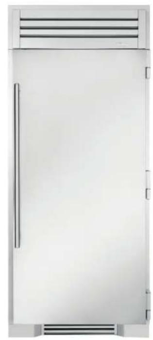
natural_image
Front view of a white stainless steel refrigerator with ventilation grilles and a vertical door (no text or symbols visible)TRUE RESIDENTIAL®
TR-30 / TR-36
INSTALL GUIDE AND USER'S MANUAL
"C" REVISION

PRESERVE THE MOMENT®
TEC_TM_009|REV.IIEN
03/21/2023
TR 30/36 INSTALL MANUAL
THANK YOU
FOR YOUR PURCHASE
INSTALLATION CHECKLIST
To ensure no part of the installation process has been overlooked, complete the checklist below.
□ Have all packaging materials been removed?
☐ Are the anti-tip brackets securely installed and properly engaging the unit?
☐ Has the unit been properly leveled? Do all leveling legs touch the floor?
□ Is the kickplate installed?
☐ Is the doorstop being installed (if needed)?
□ Does the customer understand the unit's operation?
□ Has the customer been given the key and literature package?
□ Have all stainless steel surfaces been inspected for imperfections?*
□ Is the unit operating correctly? If not, is the unit plugged in? Is the control turned on?
* To be completed by either an installer with the customer or an authorized TRUE dealer upon completion of installation. Stainless steel doors, handles, and shelves are covered by a limited 30-day warranty for cosmetic defects.
CONTENTS
SAFETY INFORMATION & OWNERSHIP
REFRIGERANT SAFETY & WARNING INFORMATION 8
BASIC SAFETY & WARNING PRECAUTIONS 8
CABINET DISPOSAL WARNING 9
OWNERSHIP 10
NOTICE TO CUSTOMER 10
APPLIANCE LOCATION 10
REGISTER YOUR PRODUCT 10
SERIAL LABEL LOCATION 10
CONTACT INFORMATION 10
PRIOR TO INSTALLATION
ROUGH OPENINGS & PLAN VIEWS 12
ANTI-SWEAT FOAM END PANELS 14
ELECTRICAL SAFETY 15
OPTIONAL ICEMAKER REQUIREMENTS
(TR-30FRZ/36FRZ-IM-C) 17
WINE RACK HANDLE FINISH APPLICATION
(TR-30DZW) 20
SIDE-BY-SIDE INSTALLATION PLAN VIEWS
TR-30 / TR-42 22
TR-30 /TR-48 23
TR-30 / TR-30 24
TR-30 / TR-30 / TR-30 25
TR-36REF / TR-36REF 26
TR-36REF / TR-30REF 27
INSTALLATION
UNCRATING 30
ANTI-TIP BRACKET INSTALLATION 33
LEVELING 34
KICKPLATE INSTALLATION 35
JOINING KIT INSTALLATION 36
CABINET SETUP
SHELVING, BINS, DRAWERS 42
REFRIGERATOR STORAGE 42
FREEZER STORAGE 45
OPTIONAL ICEMAKER 46
TEMPERATURE ADJUSTMENT 49
MODE NAVIGATION 50
SHOWROOM MODE 51
ACCENT LIGHTING SYSTEM 52
ALARM NAVIGATION 53
NOTIFICATION ALERTS 54
ICE MENU NAVIGATION 55
CONTENTS
DUAL ZONE OPERATION
TURN ON/OFF 58
TEMPERATURE ADJUSTMENT 59
MODE NAVIGATION 60
SHOWROOM MODE 61
ACCENT LIGHTING SYSTEM 62
CHANGE TRULUMINA® LIGHT COLOR 62
ALARM NAVIGATION 63
NOTIFICATION ALERTS 64
MAINTENANCE, CARE & CLEANING
INTERIOR ACCESSORIES 66
DOOR REMOVAL 66
CONDENSER COIL CLEANING 67
CONDENSATION 67
HANDLE TIGHTENING 67
WATER FILTER REPLACEMENT (OPTIONAL ICEMAKER ONLY) 68
STAINLESS STEEL EQUIPMENT CARE & CLEANING 69
COMPONENT REPLACEMENT 71
SERIAL LABEL LOCATION 71
CONTACT US 71
WARRANTY
WARRANTY 75
NOTE: AS WE STRIVE FOR CONTINUOUS IMPROVEMENTS, FEATURES AND SPECIFICATIONS ARE SUBJECT TO CHANGE WITHOUT NOTICE.
30 & 36 INCH REFRIGERATOR, FREEZER & DUAL ZONE COLUMN
30" REFRIGERATOR BEVERAGE COLUMN
STAINLESS GLASS DOOR
30" REFRIGERATOR COLUMN
STAINLESS SOLID DOOR
30" REFRIGERATOR COLUMN
STAINLESS GLASS DOOR
30" FREEZER COLUMN
STAINLESS SOLID DOOR
30" DUAL ZONE
WINE COLUMN
STAINLESS GLASS DOOR
natural_image
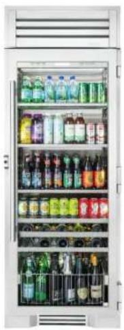
Interior view of a white refrigerator with shelves stocked with various bottled beverages (no visible text or labels)
natural_image
Front view of a white refrigerator with ventilation grilles and a handle (no text or symbols visible)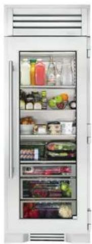
natural_image
Interior view of a refrigerator with shelves full of food items (no visible text or labels)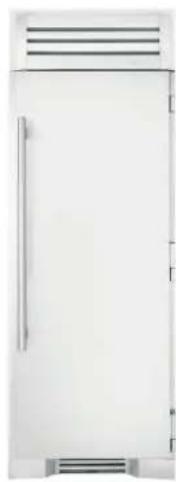
natural_image
Front view of a white refrigerator with ventilation grilles and a vertical door (no text or symbols visible)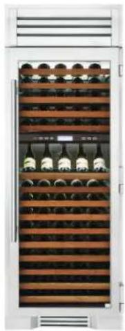
natural_image
Front view of a multi-level wine rack cabinet with wooden shelves and glass bottles (no visible text or labels)
x150
natural_image
Front view of a white stainless steel refrigerator with ventilation grilles and a vertical door (no text or symbols visible)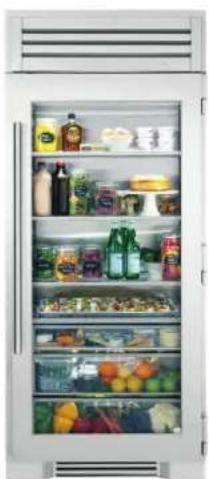
natural_image
Interior view of a modern refrigerator with shelves full of food and drinks (no visible text or labels)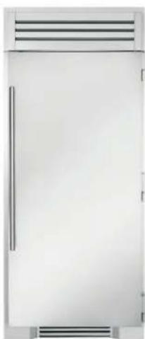
natural_image
Front view of a white stainless steel refrigerator with ventilation grilles and a vertical door (no text or symbols visible)NOTES
SAFETY INFORMATION & OWNERSHIP
REFRIGERANT SAFETY & WARNING INFORMATION
BASIC SAFETY & WARNING PRECAUTIONS
CABINET DISPOSAL WARNING
PROPER DISPOSAL OF THE CABINET
OWNERSHIP
NOTICE TO CUSTOMER
REGISTER YOUR PRODUCT
SERIAL LABEL LOCATION
CONTACT INFORMATION

PRESERVE THE MOMENT®
SAFETY INFORMATION & OWNERSHIP

WARNING! Use this appliance for its intended purpose as described in this Installation Manual.
This appliance is to be installed in accordance with local and federal regulations, as well as Safety Standard for Refrigeration Systems ANSI/ASHRAE 15.
REFRIGERANT SAFETY & WARNING INFORMATION
See the serial label inside the cabinet for the units refrigeration type. For Hydrocarbon Refrigeration (R-600a only), see below:

DANGER! Risk of fire or explosion. Flammable refrigerant used.
- DO NOT use mechanical devices to accelerate the defrost process or to clean.
- DO NOT puncture, pierce, or burn refrigerant tubing.
- Be aware that refrigerants may not contain an odor.
- Store the appliance in a room without continuously operating ignition sources.
- Follow handling instructions carefully.
- To be repaired only by trained service personnel.
- Consult repair manual/owner's guide before attempting to service this product. All safety precautions must be followed.
- Dispose of properly in accordance with local and federal regulations. Follow all safety precautions.

CAUTION! Keep all ventilation openings clear of obstruction in the appliance enclosure or in the structure housing the appliance.
BASIC SAFETY & WARNING PRECAUTIONS
- Take care during operation, maintenance or repairs to avoid cuts or pinching from any part/component of the cabinet.
- Units may pose a tipping hazard while uncrating, during installation, or when moving the unit.
- Ensure the unit is properly installed and located in accordance with the Installation Instructions before use.
- This appliance is not to be used, cleaned or maintained by persons (including children) with reduced physical, sensory or mental capabilities or lack of experience and knowledge, unless they have been given supervision or instruction.
- DO NOT allow children to play with the appliance or climb, stand, or hang on the unit's shelves to prevent damage to the refrigerator and personal injury.
- DO NOT touch the cold surfaces in the freezer compartment when hands are damp or wet. Skin may stick to these extremely cold surfaces.
- Unplug the refrigerator before cleaning and making repairs.
- Setting temperature controls to the 0 position or powering off an electronic control may not remove power from all components (e.g., light circuits, perimeter heaters, and evaporator fans).
- DO NOT store or use gasoline, or other flammable vapors and liquids, in the vicinity of this or any other appliance.
SAFETY INFORMATION & OWNERSHIP
- DO NOT store explosive substances such as aerosol cans with a flammable propellant in this appliance.
- Keep fingers out of the "pinch point" areas; clearances between the doors and cabinet are necessarily small; be careful closing doors when children are in the area.
- DO NOT use electrical appliances inside the food storage compartments of the units unless the appliances are of the type recommended by the manufacturer.
NOTE: ALL SERVICING MUST BE PERFORMED BY A QUALIFIED TECHNICIAN.
CABINET DISPOSAL WARNING

DANGER! RISK OF CHILD ENTRAPMENT
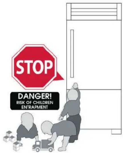
PROPER DISPOSAL OF THE CABINET
Child entrapment and suffocation are not problems of the past. Junked or abandoned refrigerators are still dangerous, even if they will sit for "just a few days." If you are getting rid of your old refrigerator, please follow the instructions below to help prevent accidents.
Before throwing away your old refrigerator or freezer:
• Take off the doors.
- Leave the shelves in place so that children may not easily climb inside.

DANGER! Risk of fire or explosion.
Flammable insulation and/or refrigerant used. Dispose of all in accordance with local and federal regulations. Follow all safety precautions.
SAFETY INFORMATION & OWNERSHIP
OWNERSHIP
To ensure that your unit works properly from the first day, it must be installed properly. We highly recommend a trained refrigeration mechanic and electrician install your TRUE equipment. The cost of a professional installation is money well spent.
This appliance is intended to be used in household and similar applications such as:
- Staff kitchen areas in shops, offices and other working environments.
• Bed and breakfast type environments.
• Catering and similar non-retail applications.
Before you start to install your TRUE unit, carefully inspect it for freight damage. If damage is discovered, do not install the unit or put it in service. Notify TRUE customer service and immediately file a claim with the delivery freight carrier.
TRUE is not responsible for damage incurred during shipment.
For any questions about installation, please contact your TRUE dealer or TRUE Residential Technical Service at 844-746-9423 or trueresidentialservice@truemfg.com. Please have your model and serial number available.
NOTICE TO CUSTOMER
Loss or spoilage of products in your refrigerator/freezer is not covered by warranty. In addition to following recommended installation procedures, run the refrigerator/freezer for 24 hours prior to usage to verify it
natural_image
Illustration of a translucent ice cube with bubbles and liquid droplets (no text or symbols)APPLIANCE LOCATION
This appliance has been tested for IEC to ISO Climate Class 5 [104°F (40°C) temperature, 40% relative humidity].
REGISTER YOUR PRODUCT
To qualify for TRUE's extended 7-12 year parts only sealed system warranty, you must register your product* within 12 months of the unit's installation date. To register your unit, complete and submit the form at true-residential.com/product-registration. For warranty details, please see page 75.

* Please note that ice machines do not qualify for this extended warranty.
SERIAL LABEL LOCATION
The serial label is located on the left wall near the freezer wire basket or the refrigerator upper drawer. See fig. 1.
This label contains important information such as your model name and serial number. Please have this information on hand when contacting TRUE so we can better assist you with your service- or parts-related inquiries.
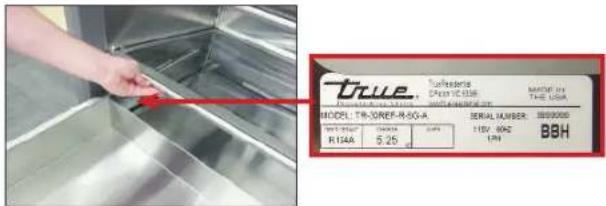
FIG. 1. Serial label location.
CONTACT INFORMATION
CUSTOMER SERVICE
Phone: 888-616-8783
info@true-residential.com
WARRANTY DEPARTMENT
Phone: 844-849-6179
TrueResidentialWarranty@truemfg.com
SERVICE DEPARTMENT
Phone: 844-746-9423
TrueResidentialService@truemfg.com
PRIOR TO INSTALLATION
ROUGH OPENINGS & PLAN VIEWS
ANTI-SWEAT FOAM END PANELS
ELECTRICAL SAFETY
POWER CORD
OPTIONAL ICEMAKER REQUIREMENTS (TR-30FRZ/36FRZ-IM-C)
WIRE RACK HANDLE FINISH APPLICATION (TR-30DZW)

PRESERVE THE MOMENT®
PRIOR TO INSTALLATION
ROUGH OPENINGS & PLAN VIEWS
NOTE: DUE TO THE WEIGHT OF THIS UNIT, TRUE RECOMMENDS CONSULTING A FLOORING EXPERT PRIOR TO INSTALLATION. THE FLOORING BENEATH THE UNIT SHOULD BE RATED TO SUPPORT ≥150 LBS/FT ^2 (732.3 6 KG/M ^2 )
NOTE: IT IS NOT RECOMMENDED TO INSTALL UNITS SIDE BY SIDE WITH HINGES TOUCHING EACH OTHER. IF YOU PLAN TO INSTALL UNITS HINGE TO HINGE, CALL TECH SUPPORT AT 844-746-9423 FOR INSTALLATION INSTRUCTIONS.
Flush installation: The front face of the unit is flush with the surrounding cabinets
Proud (standard) Installation: The front face of the unit extends beyond the surrounding cabinets
TR-30 Rough Opening Dimensions
| Flush Install Proud Install | ||
| Width | 30-1/4"(768.35 mm) | 29-3/4"(755.65 mm) |
| Depth | 25-25/32"(654.84 mm) | 23-25/32"(604.04 mm) |
| Height | 84-1/4"(2,139.95 mm) | 84*(2,133.6 mm) |
TR-36 Rough Opening Dimensions
| Flush Install Proud Install | ||
| Width | 36-1/4"(920.75 mm) | 35-3/4"(908.05 mm) |
| Depth | 25-25/32"(654.84 mm) | 23-25/32"(604.04 mm) |
| Height | 84-1/4"(2,139.95 mm) | 84"(2,133.6 mm) |
Dimensions may vary by ± 1/8" (3.2 mm)
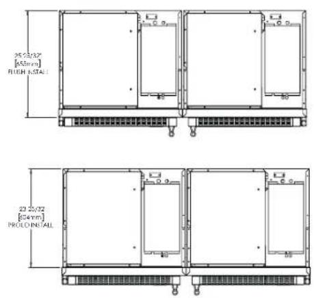
TR-30/36 - TOP VIEW FLUSH INSTALL
![28.2X32" [655mm] FUSH INSTALL](/content/2026/05/1045809/images/64e2e71203f1dba1945849579327b42fc4cda28fd808203910710592273a2880.jpg)
TR-30/36 - TOP VIEW PROUD INSTALL
![23.25/32" [604mm] PROUD INSTALL](/content/2026/05/1045809/images/57edd148838e72ac7d5392230b142d43759d67e14aadee314590ebec84d7fdff.jpg)
TR-30/36 - FRONT VIEW
ROUGH OPENING & ELECTRIC AREA
![ELECTRICAL AREA 8" [203mm] 2" [51mm] 77" [1956mm] 84 1/4" [2140mm] FLUSH INSTALL 84" [2134mm] PROUD INSTALL PROUD INSTALL TR-30 - 29-3/4" (756.7 mm) TR-36 - 35-3/4" (908 mm) FLUSH INSTALL TR-30 - 30-1/4" (769 mm) TR-36 - 36-1/4" (921 mm)](/content/2026/05/1045809/images/b619f54208e8d5462ce195556c8dc84f5bbeaf5ffc2cd34dec776f30582e3921.jpg)
PRIOR TO INSTALLATION
![20 11/16" [525mm] 135" 29 9/16" [751mm] 23 25/32" [604mm] 90" 55 1/4" [1403mm] 31 15/32" [799mm] 29 15/32" [748mm]](/content/2026/05/1045809/images/d461578089a824dfe15d9cdcf9f2514759a4261d4bc1758a6bae00de6c9dc3b7.jpg)
TR-30 - TOP VIEW TR-30 - FRONT VIEW
![30" [762mm] 67 29/32" [1725mm] DOOR HEIGH 83 15/16" [2132mm] 72 5/8" [1845mm]](/content/2026/05/1045809/images/a79d9f23a6177ac0ac3bb87529d173b0bb241fd134c1f31fad805faa70202581.jpg)
![29/16" [65mm] 30 15/32" [74mm] 27 29/32" [709mm] 25 25/32" [655mm] 3 15/16" [100mm]](/content/2026/05/1045809/images/e3f2b07bb66494c298b2bde2412e45927eea3a6a14f015c4725ebd2ec903c68d.jpg)
TR-30 - SIDE VIEW
Dimensions may vary by ± 1/8" (3.2 mm)
![24 13/16" [631mm] 135° 35 9/16" [903mm] 23 25/32" [604mm] 90° 61 1/4" [1556mm] 37 15/32" [952mm] 35 15/32" [901mm]](/content/2026/05/1045809/images/b503913adeaf1fa30ecaabd2b015a2975c15a2d9b7a6a3156004a1bda91b59db.jpg)
TR-36 - TOP VIEW TR-36 - FRONT VIEW
![36" [915mm] 67 29/32" [1725mm] DOOR HEIGHT 83 15/16" [2132mm] 72 5/8" [1845mm]](/content/2026/05/1045809/images/bf5a1c5e0bbddb27e4aa8d4c5221c13bd2079a122c9102998683c0bb7422fc56.jpg)
![2 9/16" [65mm] 30 15/32" [774mm] 27 29/32" [709mm] 25 25/32" [655mm] 3 15/16" [100mm]](/content/2026/05/1045809/images/944ba0a894256e5f90641ee44922527307abb9dd1bd59c03bda07d73d3e293ef.jpg)
TR-36 - SIDE VIEW
Dimensions may vary by ± 1/8" (3.2 mm)
PRIOR TO INSTALLATION
ANTI-SWEAT FOAM END PANELS
When installing two or more TRUE units side-by-side, be sure to leave at least a 5/8" (15.88 mm) gap between the cabinets, or install foam pads between the cabinets and on any side without this gap, to prevent moisture from developing on applications.
If installing anti-sweat foam end panels, TRUE recommends applying a panel to each of the units being joined together. To order foam pads, contact our parts department at 844-849-6226 or TrueResidentialParts@TrueMfg.com.
SITE PREPARATION
ELECTRICAL SAFETY
Power Supply: 115VAC, 60hz
Circuit Breaker: 15 Amp
Receptacle: 3-Prong Grounding-Type
- For all built-in models, the electrical supply should be located within the indicated shaded area shown in the figure below.
- Be sure to follow the National Electrical Code, as well as local codes and ordinances, when installing the receptacle.
- A ground fault circuit interrupter (GFCI) is not recommended and may cause interruption of operation.
- The power cord from this appliance is equipped with a grounding plug which minimizes the possibility of electric shock hazard.
- The wall outlet and circuit should be checked by a licensed electrician to be sure the outlet is wired with the correct polarity and properly grounded.
- If the outlet is a standard 2-prong outlet, it is your personal responsibility and obligation to have it replaced with a properly grounded wall outlet.
- DO NOT, under any circumstances, cut or remove the ground prong from the power cord. For personal safety, this appliance must be properly grounded.
- The refrigerator/freezer should always be plugged into a dedicated electrical circuit. This provides the best performance and prevents building wiring circuits from overloaded, which could cause a fire hazard from overheated wires.
• NEVER USE AN ADAPTER PLUG!
An adapter plug alters the original equipment manufacturer (OEM) plug configuration when connecting it to a power source. TRUE will not warranty any refrigerator/freezer that has been connected to an adapter plug.
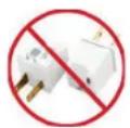
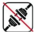
• NEVER USE AN EXTENSION CORD! An
extension cord is any component that adds length to the OEM power cord when connecting it to a power source. TRUE will not warranty any refrigerator/freezer that has been connected to an extension cord.
- Before your new unit is connected to a power supply, check the incoming voltage. If the recorded voltage is less than the rated voltage for operation (+/-5%) and amp rating, correct immediately. Refer to the serial label for this voltage requirement.
- NEVER unplug your refrigerator/freezer by pulling on the power cord. Always grip the plug firmly and pull straight from the outlet.
- When moving the refrigerator/freezer for any reason, take care to no roll over or damage the power cord.
- DO NOT use a power cord that shows cracks or abrasion damage along its length or at either end. Immediately repair or replace all power cords that have become frayed or otherwise damaged.
- If the supply power cord is damaged, replace it with OEM components. To avoid hazard, this should be done by a licensed service provider or similarly qualified person.
SITE PREPARATION
POWER CORD
INSTALLATION
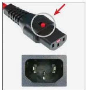
Fully seat the power cord into the cabinet receptacle until it locks in position. See fig. 1.
REMOVAL
Depress the red button. See fig. 2.
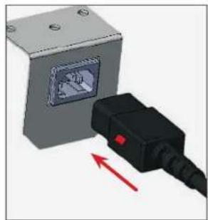
natural_image
Diagram showing a device with a screen and a black plug connected by a red arrow (no text or symbols present)FIG. 1. Fully insert the power cord into the receptacle.
natural_image
Close-up of a black electrical plug with a red circular highlight and an inset showing three pins (no text or symbols visible)FIG. 2. Push the red button to remove the plug.
TR-30/36
FRONT VIEW ROUGH OPENING & ELECTRICAL AREA
![ELECTRICAL AREA 8" [203mm] 2" [51mm] 84 1/4" [2140mm] FLUSH INSTALL 84" [2134mm] PROUD INSTALL 77" [1956mm] PROUD INSTALL TR-30 - 29-3/4" (756.7 mm) TR-36 - 35-3/4" (908 mm) FLUSH INSTALL TR-30 - 30-1/4" (769 mm) TR-36 - 36-1/4" (921 mm)](/content/2026/05/1045809/images/bab0ef632d06fb036dc07aea35819ffec8303d08b2224db346883c7c7c865bad.jpg)
NOTE: DIMENSIONS MAY VARY BY ± 1/8" (3.175 mm)
SITE PREPARATION
OPTIONAL ICEMAKER REQUIREMENTS (TR-30FRZ/36FRZ-IM-C)
WATER SUPPLY REQUIREMENTS

WARNING! Only connect to a potable water supply!
Units with optional ice makers come with 20" (508 mm) of polyethylene tubing with a 1/4" O.D. push connector for customer attachment.
Before installing your unit, prepare the water supply line. Please see plumbing requirements in the plumbing requirements table.
- Purge the water line prior to final connection to the unit. This removes any debris present in the line.
- Only connect to a potable water supply!
- Do not connect to a hot water supply!
- Install the water filter before turning on the water supply to the icemaker. See "Water Filter Installation" (page 18).
- A copper line is not recommended for this application.
- Check all water line fittings for leaks.
- Tape the supply line to the floor before moving the unit into its final installation location.
- In the water connection area (see the rough opening illustration), tape the water line to the floor.
natural_image
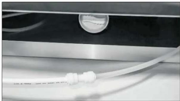
Close-up of a metallic surface with a white plastic hose and circular opening, no visible text or symbolsFIG. 1. Water line connection. Fitting included, PEX not included
Plumbing Requirements
| Water Supply | 1/4' PEX tubing (1/4" O.D. lines and fittings not includedNOTE: Copper line is not recommended |
| Flow Rate 0.5 gpm / 1.89 lpm | |
| Operating Pressure 30-100 psi (207-689 kPa) | |
| Incoming Water Temperature 33-10 0°F (0.6 -3 8°C) |
![ELECTRICAL AREA 8" [203mm] 2" [51mm] WATER AREA 1 1/2" [38mm] 2 1/2" [64mm] 6" [152mm] TYP PROUD INSTALL TR-30 - 29-3/4" (756.7 mm) TR-36 - 35-3/4" (908 mm) FLUSH INSTALL TR-30 - 30-1/4" (769 mm) TR-36 - 36-1/4" (921 mm) 77" [1956mm] 84 1/4" [2140mm] FLUSH INSTALL PROUD INSTALL 84" [2134mm]](/content/2026/05/1045809/images/9be15ca8adbb37701e483b75ec4fd00fb3fb1d7c1d1250335c7ebf0d5d42219d.jpg)
NOTE: DIMENSIONS MAY VARY BY ± 1/8" (3.175 mm)
INSTALLATION
WATER FILTER INSTALLATION & PERFORMANCE DATA
The water filter filters sediment and removes unpleasant taste and odor. Install the provided water filter before using the icemaker. The unit will not make ice until the water filter is installed.
PROCEDURE
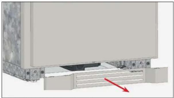
- Remove the kickplate. See fig. 1.
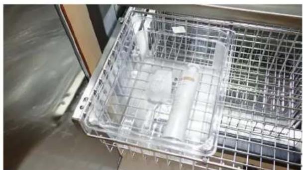
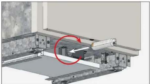
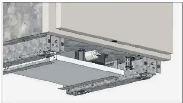
- Insert the provided water filter (see fig. 2) and rotate the filter clockwise. (See figs. 3 and 4).
- Reinstall the kickplate.
WATER FILTER PERFORMANCE DATA
- This system has been tested according to NSF/ANSI Standard 42, 53, 372, 401, P473 and CSA B483.1 for reduction of the substances listed below. The concentration of the indicated substances in water entering the system was reduced to a concentration less than or equal to the permissible limit for water leaving the system, as specified in NSF/ANSI Standards 42, 53, 372, 401, P473 and CSA B483.1.
- Systems certified for cyst reduction may be used on disinfected waters that may contain filterable cysts. The system conforms to NSF/ANSI 42, 53, 372, 401, P473 and CSA B483.1 for the specific performance claims as verified and substantiated by test data. Conforms to NSF/ANSI 53 for VOC reduction. See below for individual contaminants and reduction performance.
NOTE: TESTING WAS PERFORMED UNDER STANDARD LABORATORY CONDITIONS, ACTUAL PERFORMANCE MAY VARY.
natural_image
Mechanical assembly diagram showing a component with a red arrow indicating direction (no text or symbols present)FIG. 1. Pull the kickplate from the cabinet.
natural_image
Interior view of a transparent metal rack with internal components (no visible text or symbols)FIG. 2. Locate the provided water filter shipped in the ice bucket.
natural_image
Mechanical assembly diagram showing a shaft mounted on a metal frame with a red circular arrow indicating motion (no text or symbols present)FIG. 3. Insert the water filter and rotate it clockwise.
natural_image
Mechanical assembly diagram showing a shaft mounted on a metal frame with mounting brackets (no text or symbols visible)FIG. 4. Installed water filter.
INSTALLATION
WATER FILTER INSTALLATION & PERFORMANCE DATA (CONT.)
- System to be used with municipal or well water sources treated and tested on regular basis to ensure bacteriological safe quality. Do not use with water that is microbiologically unsafe or of unknown quality without adequate disinfection before or after the system.
- It is essential that the manufacturer's recommended installation, maintenance and filter replacement requirements be carried out for the product to perform as advertised. Manufactured by Aquamor, LLC, Temecula, CA.
Filter Specifications
| Flow Rate | 0.5 gpm / 1.89 lpm |
| Operating Temperature | 33-100°F (0.6-38°C) |
| Operating Pressure | 30-100 psi (kPa) |
| Capacity | 300 gal. (1,136 L) or six months |

Contaminant and Reduction Performance
| Contaminant | % of reduction | Influent Concentration | Max Allowable |
| CHLORINE >97% 2.0 mg/L 1.0 mg/L | |||
| ALACHLOR* >98% 0.050 | 0.001 | ||
| Asbestos 99.98% 189 MFL 99% | |||
| ATRAZINE* >97% 0.100 | 0.003 | ||
| BENZENE* >99% 0.081 | 0.001 | ||
| BISPHENOL 99.1% 2.058 mg/L <0.300ng/L | |||
| BROMODICHLOROMETHANE (TTHM)* | >99.8% | 0.300 | 0.015 |
| BROMOFORM (TTHM)* | >99.8% | 0.300 | 0.015 |
| CARBOFURAN (Furadan)* | >99% | 0.19 | 0.00 |
| Carbon Tetrachloride | >95% | 0.014 | 0.005 |
| CHLORDANE | >99.5% | 0.04 +/-10% | 0.002 |
| CHLOROBENZENE (Monochlorobenzene)* | >99% | 0.077 | 0.00 |
| CHLOROPICRIN* | 99% | 0.015 | 0.0002 |
| CHLOROFORM (TTHM)* (surrogate chemical) | >99.8% | 0.300 | 0.015 |
| 2, 4-D* | 98% | 0.110 | 0.0017 |
| CYST (Giardi; Cryptosporidium; Entamoeba; Toxoplasma) | >99.95% | MINIMUM 50,000/L | 99.95% REDUCED PERIODIRALN |
| Cryptosporidium (see CYST) | >99.95% | MINIMUM 50,000/L | 99.95% REDUCED PERIODIRALN |
| DBCP (see Dibromochloropropane)* | >99% | 0.052 | 0.00002 |
| 1,2-DCA (see 1,2-DICHLOROETHANE)* | 95% | 0.088 | 0.0048 |
| 1,1-DCE (see 1,1-DICHLOROETHYLENE)* | >99% | 0.083 | 0.001 |
| DIBROMOCHLOROMETHANE (THM Chlorodromonethane)* | >99.8% | 0.300 | 0.015 |
| DIBROMOCHLOROPROPANE (DBCP)* | >99% | 0.052 | 0.00002 |
| o-DICHLOROBENZENE (1,2 Dichlorobenzene)* | >99% | 0.080 | 0.001 |
| p-DICHLOROBENZENE (para-Dichlorobenzene) | >98% | 0.040 | 0.001 |
| 1,2-DICHLOROETHANE (1,2-DCA)* | 95% | 0.088 | 0.0048 |
| 1,1-DICHLOROETHYLENE (1,1-DCE)* | >99% | 0.083 | 0.001 |
| CIS-1,2-DICHLOROETHYLENE* | >99% | 0.170 | 0.0005 |
| TRANS-1,2- DICHLOROETHYLENE* | >99% | 0.086 | 0.001 |
| 1,2-DICHLOROPROPANE (Propylene Dichloride)* | >99% | 0.080 | 0.001 |
| CIS-1,3- DICHLOROPROPYLENE* | >99% | 0.079 | 0.001 |
| DINOSEB* | 99% | 0.170 | 0.0002 |
| EDB (see ETHYLENE DIBROMIDE)* | >99% | 0.044 | 0.00002 |
| ENDRIN | 99% | 0.053 | 0.00059 |
| Entamoeba (see CYSTS) | 99.95% | MINIMUM 50,000/L | 99.95% REDUCED PERIODIRALN |
| ESTRONE | 96.9% | 0.1388 mg/L | <0.020 mg/L |
| ETHYLBENZENE* | >99% | 0.088 | 0.001 |
| ETHYLENE DIBROMIDE (EDB)* | >99% | 0.044 | 0.00002 |
| Furadan (see CARBOFURAN)* | >99% | 0.19 | 0.00 |
| Giardia Lambila (see CYST) | >99.95% | MINIMUM 50,000/L | 99.95% REDUCED PERIODIRALN |
| HALOACETONITRILES (HAN)* | |||
| BROMOCHLOROACETONITRILE | 98% | 0.022 | 0.0005 |
| DIBROMOACETONITRILE | 98% | 0.024 | 0.0006 |
| HALOACETONITRILES (HAN)* | |||
| DICHLOROACETONITRILE | 98% | 0.0096 | 0.0002 |
| TRICHLOROACETONITRILE | 98% | 0.015 | 0.0003 |
| Contaminant | % of reduction | Influent Concentration | Max Allowable |
| HALOKETONES (HK):* | |||
| 1,1-DICHLORO-2-PROPANONE | 99% | 0.0072 | 0.0001 |
| 1,1,1-TRICHLORO-2-PROPANONE | 96% | 0.0082 | 0.0003 |
| HEPTACHLOR* | >99% | 0.25 | 0.00001 |
| HEPTACHLOR EPOXIDE* | 98% | 0.0107 | 0.0002 |
| HEXACHLOROBUTADIENE (Perchlorobutadiene)* | >98% | 0.044 | 0.001 |
| HEXACHLOROCYCLOPENTADIENE* | >99% | 0.060 | 0.000002 |
| IBUPROFEN 96.7% 0.432 mg/L <0.060 mg/L | |||
| LEAD (pH 6.5) | >99.3% | 0.15 +/- 10% | 0.010 |
| LEAD (pH 8.5) | >99.3% | 0.15 +/- 10% | 0.010 |
| LINDANE* >99% 0.055 0.00001 | |||
| METHOXYCHLOR* | >99% | 0.050 | 0.0001 |
| Methylbenzene (see TOLUENE)* | >99% | 0.078 | 0.00 |
| Mercury (pH 6.5) | 74.9% | 0.0059 | 0.002 |
| Mercury (pH 8.5) | 97.8% | 0.0061 | 0.002 |
| Monochlorobenzene (see CHLOROBENZENE)* >99% | 0.077 | 0.001 | |
| NAPROXEN | 95.3% | 0.130 mg/L | <0.020 mg/L |
| NONYLPHENOL | 97.1% | 2.058 mg/L | <0.200 mg/L |
| POLYCHLORINATED BIPHENYLS(PCBs, Aroclor 1260) | >99.9% | 0.01 +/- 10% | 0.0005 |
| PCE (see Tetrachloroethylene) | >96% | 0.014 | 0.00 |
| PENTACHLOROPHENOL* | >99% | 0.096 | 0.00 |
| Perchlorobutadiene (see HEXACHLOROBUTADIENE)* | >98% | 0.044 | 0.001 |
| PFOA | 98.0% | 0.0005 mg/L | <0.00007 mg/L |
| PFOS | 98.0% 0.001 mg/L | <0.00007 mg/L | |
| Phenytoin | 94.7% | 0.2173 mg/L | <.030 mg/L |
| Propylene Dichloride (see 1,2 -DICHLOROPRANI)* | >99% | 0.080 | 0.001 |
| SIMAZINE* >97% 0.120 | 0.004 | ||
| STYRENE (Vinylbenzene)* | >99% | 0.150 | 0.0005 |
| 1,1,1-TCA (see 1,1,1 - TRICHLOROETHANE)* | 95% | 0.084 | 0.0046 |
| 1,2,4-Trichlorobenze | >99% | 0.215 | 0.07 |
| TCE (see TRICHLOROETHYLENE)* | >99% | 0.180 | 0.0010 |
| 1,1,2,2- TETRACHLOROETHANE* | >99% | 0.081 | 0.00 |
| TETRACHLOROETHYLENE* | >99% | 0.081 | 0.00 |
| TOLUENE (Methylbenzene)* | >99% | 0.078 | 0.00 |
| TOXAPHENE | >92.9% | 0.015 +/- 10% | 0.003 |
| 2,4,5-TP (Silvox)* | 99% | 0.270 | 0.0016 |
| Toxoplasma (see CYST) | >99.95% | MINIMUM 50,000/L | ### ### ### ### ### ### ### |
| TRIBROMOACETIC ACID* | 0.042 | 0.001 | |
| 1,1,1-TRICHLOROETHANE (1,1,1-TCA)* | 95% | 0.084 | 0.0046 |
| 1,1,2-TRICHLOROETHANE* | >99% | 0.150 | 0.0005 |
| TRICHLOROETHYLENE (TCE)* | >99% | 0.180 | 0.0010 |
| TRIHALOMETHANES (TTHM) (Chloroform; Bromoform; Bromodichloromethane; Dibromochloromethane) | >99.8% | 0.300 | 0.015 |
| Unsym- Trichlorobenzene isee 1,2,4-TRICHLOROBENZENE* | >99% | 0.160 | 0.0005 |
| Vinylbenzene (see STYRENE)* | >99% | 0.150 | 0.0005 |
| XYLENES (TOTAL)* | >99% | 0.070 | 0.00 |
PRIOR TO INSTALLATION
WIRE RACK HANDLE FINISH APPLICATION (TR-30DZW)
See finish (e.g., paint or stain) for application instructions and drying / curing times. Drying / Curing times vary by finish. Follow recommended guidelines associated with treating unfinished natural cherry wood.
NOTE: REMOVE THE WINE RACK HANDLES FROM THE WINE RACK ASSEMBLY BEFORE APPLYING FINISH!
NOTE: FINISH ODORS FROM PANELS INSTALLED BEFORE FULLY DRYING / CURING CAN LINGER AND BE ABSORBED BY THE CABINET'S INTERIOR. TRUE IS NOT RESPONSIBLE FOR LINGERING FINISH ODORS INSIDE THE UNIT.
REMOVAL
REQUIRED TOOLS
• Phillips Screwdriver or Bit Driver
- Drill (optional)
PROCEDURE
- Pull the wine rack forward.
- Push the slide release tabs as indicated by the release arrows (see fig. 1) and pull the wine rack forward.
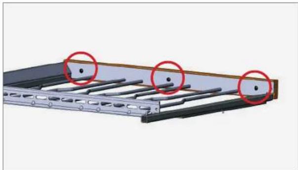
- Remove the wine rack handle from the wine rack assembly. See fig. 2.
INSTALLATION
REQUIRED TOOLS
• Phillips Screwdriver or Bit Driver
- Drill (optional)
PROCEDURE
- Install the wine rack handle on the wine rack assembly. See fig. 2.
- Position the wine rack on the slides and carefully push the wine rack towards the back of the unit.
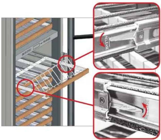
FIG. 1. Push the left release tab up and the right release tab down.
natural_image
3D model of a metal shelving unit with three red-circled mounting points (no text or symbols visible)FIG. 2. Wine rack handle screw locations.
INSTALLATION PLAN VIEWS
TR-30 / TR-42
TR-30 /TR-48
TR-30 / TR-30
TR-30 / TR-30 / TR-30
TR-36REF / TR-36REF
TR-36REF / TR-30REF

PRESERVE THE MOMENT®
INSTALLATION PLAN VIEWS
TR-30 / TR-42
TR-30 / TR-42 Rough Opening Dimensions
| Flush Install Proud Install | ||
| Width | 72-1/4" (1835.15 mm) | 71-3/4" (1822.45 mm) |
| Depth | 25-25/32" (654.84 mm) | 23-25/32" (604.04 mm) |
| Height | 84-1/4" (2,139.95 mm) | 84" (2,133.6 mm) |
Dimensions may vary by ± 1/8" (3.2 mm)
NOTE: TR-36FRZ/30FRZ-IM-C MODELS WILL REQUIRE A WATER SUPPLY. SEE "OPTIONAL ICEMAKER" FOR ROUGH OPENING.
* WATER SUPPLY REQUIRED FOR TR-42FRZ/48FRZ-C MODELS OR LATER.
FLUSH VS. PROUD INSTALL ROUGH OPENING & ELECTRICAL AREA
![20.25/32" [65mm] RUSH PISTA.1](/content/2026/05/1045809/images/a7c4880caef9b81638ec687e4d68e3d545506a3858250e42a11e72fd1a9bdd18.jpg)
![25.25/20" [64mm] FRCUO INSTAL](/content/2026/05/1045809/images/b4f92a36d8aba0f90b5353b53c03f6081d888b3e1dfdaa9e26d43706d61627c4.jpg)
![30 1/8" [765mm] 8" [200mm] 2" [3 mm] 84 1/4" [2145mm] IUS-1 INSTALL. 94 [213mm] STANDARD INSTALL 77 [195mm] Water Area* 30" [765mm] 1 1/2" [28mm] 2 1/2" [64mm] 71 3/4" [182mm] STANDARD INSTALL 6" [152mm] 72 1/4" [155mm] F. LSH INSTALL](/content/2026/05/1045809/images/41b5a8bb435234942358b1d468b71c5e7498283f6e801663e1affc6e7db820c8.jpg)
PLAN VIEW
![72 1/32" [1829mm] 83 15/16" [2132mm] 3 15/16" [100mm]](/content/2026/05/1045809/images/386ea22d34510237782c0a2ce4ddea803f67acaf91090b4ac6b15010ae2f3811.jpg)
TRUE RESIDENTIAL ^25
![29/16" [65mm] 30 15/32" [74mm] 27 29/32" [709mm] 25 25/32" [655mm]](/content/2026/05/1045809/images/451c82f0dd5e6cb85b3f9b6aadc85507d827e876130f120c8269c2814776d015.jpg)
03/21/2023Page 22 of 76
P#212530
TEC_TM_009 | REV. || EN
INSTALLATION PLAN VIEWS
TR-30 / TR-48
TR-30 / TR-48 Rough Opening Dimensions
| Flush Install Proud Install | ||
| Width | 78-1/4" (1987.55 mm) | 77-3/4" (1974.85 mm) |
| Depth | 25-25/32" (654.84 mm) | 23-25/32" (604.04 mm) |
| Height | 84-1/4" (2,139.95 mm) | 84" (2,133.6 mm) |
Dimensions may vary by ± 1/8" (3.2 mm)
NOTE: TR-36FRZ/30FRZ-IM-C MODELS WILL REQUIRE A WATER SUPPLY. SEE "OPTIONAL ICEMAKER" FOR ROUGH OPENING.
* WATER SUPPLY REQUIRED FOR TR-42FRZ/48FRZ-C MODELS OR LATER.
FLUSH VS. PROUD INSTALL ROUGH OPENING & ELECTRICAL AREA
![23.25/32 [655mm] F.L.S=INSTALL 23.25/32 [404mm] PROJL:INSTALL](/content/2026/05/1045809/images/8dfe1be81d53b85e21e63d02164a7537dcf60ff24fb7876fdf5ec065e2068b51.jpg)
![30 1/8" [765mm] 8" [200mm] 2" [51mm] 84 1/4" [2140mm] FUSH INSTALL 77 [1956mm] 84' [2136mm] STANDARD INSTALL Water Area* 36" [914mm] 77 3/4" [1975mm] STANDARD INSTALL 8' 1/4" [1935mm] FUSH INSTALL 1 1/2" [36mm] 2 1/2" [6/mm]](/content/2026/05/1045809/images/f3fd9c7ec202d3a982994240e181b35671dc8037d523a8603345025becef02ca.jpg)
PLAN VIEW
![78 1/32" [1982mm] 83 15/16" [2132mm] 3 15/16" [100mm]](/content/2026/05/1045809/images/a471b3ce58c2dcb587c096a2e7e14a6807aa191c7213b5e13ee4798d763eb4b5.jpg)
![2.9/16" [65mm] 30 15/32" [774mm] 27 29/32" [709mm] 25 25/32" [655mm]](/content/2026/05/1045809/images/a85fdae28207d26e58cd1cdb5654573f56fb299f42dbc6268c9edad9c1bf6491.jpg)
TEC_TM_009 | REV. I | EN 03/21/2023 Page 23 of 76
TR-30/36 INSTALL MANUAL
INSTALLATION PLAN VIEWS
TR-30 / TR-30
TR-30 / TR-30 Rough Opening Dimensions
| Flush Install Proud Install | ||
| Width | 60-1/4" (1530.35 mm) | 59-3/4" (1517.65 mm) |
| Depth | 25-25/32" (654.84 mm) | 23-25/32" (604.04 mm) |
| Height | 84-1/4" (2,139.95 mm) | 84" (2,133.6 mm) |
Dimensions may vary by ± 1/8" (3.2 mm)
NOTE: TR-36FRZ/30FRZ-IM-C MODELS WILL REQUIRE A WATER SUPPLY. SEE "OPTIONAL ICEMAKER" FOR ROUGH OPENING.
FLUSH VS. PROUD INSTALL ROUGH OPENING & ELECTRICAL AREA
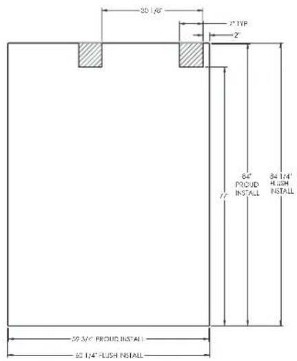
PLAN VIEW
![60 1/32" [1525mm] 83 15/16" [2132mm] 3 15/16" [100mm]](/content/2026/05/1045809/images/ed324516b00a19866713ce79610a7504a2fe39c3ce5d3a84d1962062fac5deea.jpg)
TRUE RESIDENTIAL ^25
![2 9/16" [65mm] 30 15/32" [774mm] 27 29/32" [709mm] 25 25/32" [655mm]](/content/2026/05/1045809/images/0a38649d2c1980d1ca4df033e8560b2f72ad29c97631f3801df1ade0bdb5fe79.jpg)
03/21/2023Page 24 of 76
P#212530
TEC_TM_009 | REV. || EN
INSTALLATION PLAN VIEWS
TR-30 / TR-30 / TR-30
TR-30 / TR-30 / TR-30 Rough Opening Dimensions
| Flush Install Proud Install | ||
| Width | 90-1/4" (2292.35 mm) | 89-3/4" (2279.65 mm) |
| Depth | 25-25/32" (654.84 mm) | 23-25/32" (604.04 mm) |
| Height | 84-1/4" (2,139.95 mm) | 84" (2,133.6 mm) |
Dimensions may vary by ± 1/8" (3.2 mm)
NOTE: TR-36FRZ/30FRZ-IM-C MODELS WILL REQUIRE A WATER SUPPLY. SEE "OPTIONAL ICEMAKER" FOR ROUGH OPENING.
FLUSH VS. PROUD INSTALL ROUGH OPENING & ELECTRICAL AREA
![25.0mm [30mm] FLUSH INSTAL](/content/2026/05/1045809/images/a53f0571aceaaf8c6e27595f11b8308eb6f00b3159adca22637cad01a569e477.jpg)
![(A) 2023 [100x7] PRO.C. MDA.](/content/2026/05/1045809/images/ab9e6c7b33cdbdb733ee833c8990bf3379712574fdb357a5bbdd04da2feef64e.jpg)
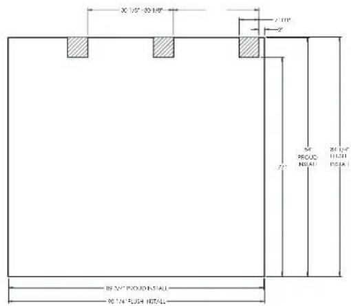
PLAN VIEW
![90 1/32" [2287mm] 83 15/16" [2132mm] 3 15/16" [100mm]](/content/2026/05/1045809/images/c8581eef437f0ef47c0585c4d8864e38bf81f511ea7412909cd5af2b0abc9d2a.jpg)
TEC_TM_009 | REV. || EN 03/21/2023 Page 25 of 76
![2 9/16" [65mm] 30 15/32" [774mm] 27 29/32" [709mm] 25 25/32" [655mm]](/content/2026/05/1045809/images/6550199d666f7a0e59f02dce621edd8ffdab09d2a686fcab4e844642217d9f83.jpg)
TR-30/36 INSTALL MANUAL
INSTALLATION PLAN VIEWS
TR-36REF / TR-36REF
TR-36 / TR-36 Rough Opening Dimensions
| Flush Install Proud Install | ||
| Width | 72-1/4" (1835.15 mm) | 71-3/4" (1822.45 mm) |
| Depth | 25-25/32" (654.84 mm) | 23-25/32" (604.04 mm) |
| Height | 84-1/4" (2,139.95 mm) | 84" (2,133.6 mm) |
Dimensions may vary by ± 1/8" (3.2 mm)
NOTE: TR-36FRZ/30FRZ-IM-C MODELS WILL REQUIRE A WATER SUPPLY. SEE "OPTIONAL ICEMAKER" FOR ROUGH OPENING.
FLUSH VS. PROUD INSTALL ROUGH OPENING & ELECTRICAL AREA
![23.25/02 [604mm] PROD INSTAL... 23.25/02 [604mm] ROLL INSTAL... 23.25/02 [65mm] ROLL INSTAL...](/content/2026/05/1045809/images/4db272bf353e5f3a29c9d9e4b844350246284d39451881e23bccd725292c811c.jpg)
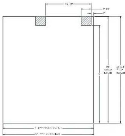
PLAN VIEW
![72 1/32" [1829mm] 83 15/16" [2132mm] 3 15/16" [100mm]](/content/2026/05/1045809/images/f1926224aaca5edd3ab8b04ef34955642cef023861c06ad3ff7da1ddadfd37db.jpg)
TRUE RESIDENTIAL ^25
![29/16" [65mm] 30 15/32" [774mm] 27 29/32" [709mm] 25 25/32" [655mm]](/content/2026/05/1045809/images/ddbfacd3bdce9fc776aa0af9815576910270ac315e4f47c3d22a0d71fd451ce3.jpg)
03/21/2023Page 26 of 76
P#212530
TEC_TM_009 | REV. || EN
INSTALLATION PLAN VIEWS
TR-36REF / TR-30REF
TR-36 / TR-30 Rough Opening Dimensions
| Flush Install Proud Install | ||
| Width | 66-1/4" (1682.75 mm) | 65-3/4" (1670.055 mm) |
| Depth | 25-25/32" (654.84 mm) | 23-25/32" (604.04 mm) |
| Height | 84-1/4" (2,139.95 mm) | 84" (2,133.6 mm) |
Dimensions may vary by ± 1/8" (3.2 mm)
NOTE: TR-36FRZ/30FRZ-IM-C MODELS WILL REQUIRE A WATER SUPPLY. SEE "OPTIONAL ICEMAKER" FOR ROUGH OPENING.
FLUSH VS. PROUD INSTALL ROUGH OPENING & ELECTRICAL AREA
![25.57.37 [604mm] PROLD INSTA-L](/content/2026/05/1045809/images/104df150ff034728c8ac500d42390d9974a6b6751d9b2b06fa3e8d46e5b3fa24.jpg)
![25.75/32 [45mm] RUM INSTALL](/content/2026/05/1045809/images/6d1a73756754946063c4650a89eef29d7aa24e0de00b9232ba0fb5b58a2ee8b5.jpg)
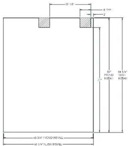
PLAN VIEW
![66 1/32" [1677mm] 83 15/16" [2132mm] 3 15/16" [100mm]](/content/2026/05/1045809/images/3c16c7fb6fdcf0f7c14f1e632dc8984da11e8df0231f2b95a2fb0f79fabdf2c5.jpg)
TEC_TM_009 | REV. I | EN 03/21/2023 Page 27 of 76
![29/16" [65mm] 30 15/32" [774mm] 27 29/32" [709mm] 25 25/32" [655mm]](/content/2026/05/1045809/images/482465e22a5cef91de4322e189d241588034e859432320e7c553c981b2ffc657.jpg)
TR-30/36 INSTALL MANUAL
NOTES
INSTALLATION
UNCRATING
ANTI-TIP BRACKET INSTALLATION
LEVELING
KICKPLATE INSTALLATION
JOINING KIT INSTALLATION

PRESERVE THE MOMENT®
INSTALLATION
UNCRATING
REQUIRED TOOLS
- Drill or ratchet
- 7/16" Deep well socket
- Cutting Tool

WARNING! TIP OVER HAZARD. Unit poses a tipping hazard when moving or during installation. Do not move the unit without the shipping brackets installed.
Do not remove the appliance from the pallet without assistance. Failure to do so may result in property damage, personal injury, or death.
NOTE: YOUR APPLIANCE MAY NOT EXACTLY MATCH FIGURES SHOWN.
PROCEDURE
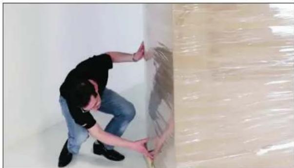
- Inspect the pallet exterior packaging for visible damage. See fig. 1. Follow TRUE's recommended procedure for accepting deliveries.
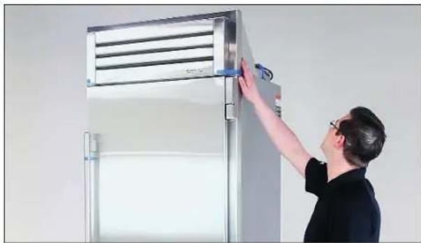
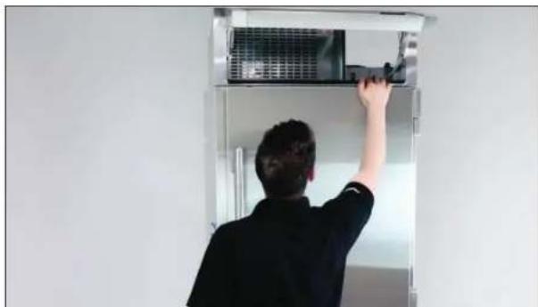
- Remove the exterior packaging. Inspect the unit's exterior for visible or cosmetic damage. See figs. 2 and 3
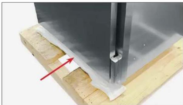
NOTE: DO NOT DISCARD THE KICKPLATE (SEE FIG. 4) IF MOVING THE UNIT A LONG DISTANCE (E.G., BETWEEN BUILDINGS OR ON STAIRS), DO NOT DISCARD THE EXTERIOR CARDBOARD.
natural_image
Man kneeling in a room with exposed ceiling and floor, handling a large wall panel (no visible text or symbols)FIG. 1. Inspect the exterior packaging for visible damage.
natural_image
Man adjusting a large stainless steel air conditioner unit (no visible text or symbols)FIG. 2. Inspect the unit's exterior for visible damage.
natural_image
Person installing or adjusting a large air conditioner unit on a metal cabinet (no visible text or symbols)FIG. 3. Be sure to inspect behind the rainshield.
natural_image
Close-up of a metallic structural component mounted on a wooden base, with a red arrow pointing to a small feature (no text or symbols visible)FIG. 4. Packaged kickplate ships tucked under the unit's front.
INSTALLATION
UNCRATING (CONT.)
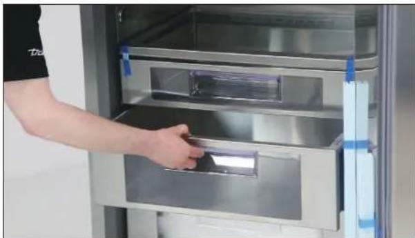
- Closely inspect the unit's interior for damage (e.g., scratches by shelving or damage to the door seal). See fig. 5.
NOTE: DO NOT REMOVE THE INTERIOR PACKAGING.
- Move the unit as close as possible to the final installation location.
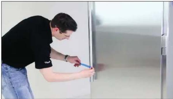
NOTE: SECURE THE DOOR BEFORE MOVING THE UNIT TO ITS FINAL LOCATION (SEE FIG. 6). REPACKAGE THE UNIT WITH THE EXTERIOR PACKAGING AS NEEDED BEFORE MOVING THE UNIT.
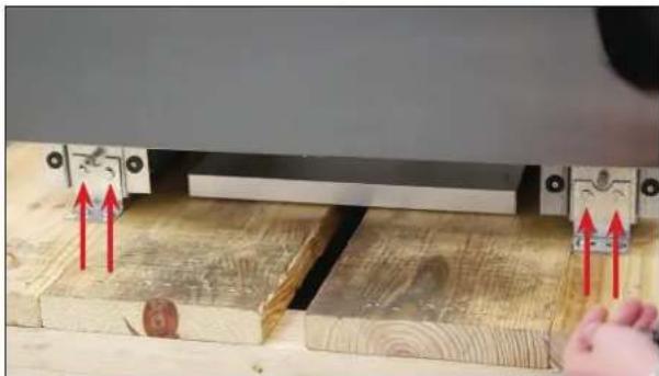
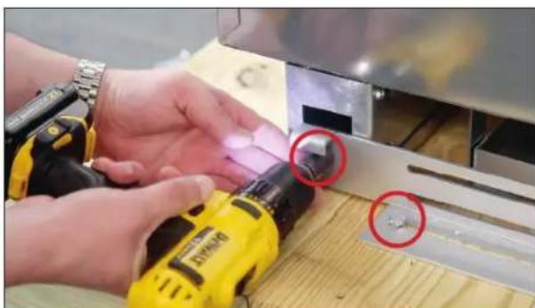
- Unbolt the shipping bracket from the castor housing. Then, remove the anti-tip bracket. See figs. 7 and 8.
NOTE: DO NOT DISCARD THE ANTI-TIP BRACKET.
natural_image
Person holding a tray inside a stainless steel refrigerator (no visible text or symbols)FIG. 5. Inspect inside the unit for visible damage. Do not remove the interior packaging.
natural_image
Man in black shirt and blue jeans using a tool on a door (no visible text or symbols)FIG. 6. Always secure the door closed before moving the appliance.
natural_image
Close-up of a wooden cutting board with red arrows indicating movement or force direction, no visible text or symbolsFIG. 7 Shipping bracket bolt locations.
natural_image
Close-up of hands using a yellow power drill on a wooden surface, with two red circles highlighting the tool area (no text or symbols visible)FIG. 8. Anti-tip bracket shipping bolt locations. Other side not shown.
INSTALLATION
UNCRATING (CONT.)
- Slightly raise the rear leveling leg rollers. Turn the front adjustment screw 1/4-1/2 turn clockwise. See fig. 9.
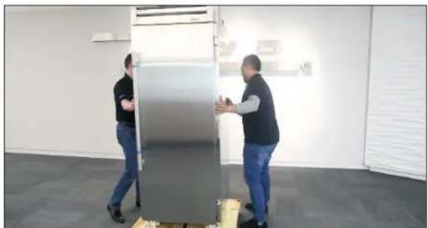
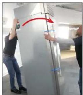
- With assistance, pull the unit off the back of the pallet. Then, remove the pallet and Carefully guide the unit to a fully upright position. See figs. 10a, 10b, and 10c.

CAUTION! Only lift with appliance moving equipment from the unit's sides, never the front or rear. See fig. 11. Failure to do so may result in personal injury or appliance damage. Do not lift the unit by handles, doors, or hinges.
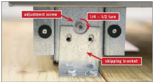
FIG. 9. Adjustment screw location. Other adjustment screw not shown.
natural_image
Two men pushing a large stainless steel refrigerator in an office setting (no visible text or symbols)FIG. 10a. With assistance, carefully walk the appliance partially off the back of the skid.
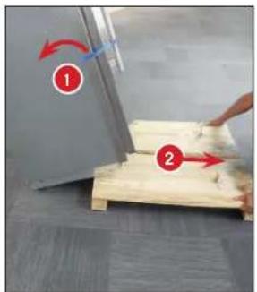
FIG. 10b. Then, tilt the unit backward and remove the skid.
natural_image
Two people installing or adjusting a large refrigerator in an indoor setting (no visible text or symbols)FIG. 10c. Carefully guide the appliance to an upright position.
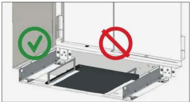
FIG. 11. Only lift with appliance moving equipment from the SIDES, NEVER the FRONT or REAR.
INSTALLATION
ANTI-TIP BRACKET INSTALLATION
KIT CONTENTS
• One (1) anti-tip bracket
• Four (4) 3/16" masonry screws
• Eight (8) #12 -2" wood screws
- Twelve (12) 1/4" washers
REQUIRED TOOLS
- Tape measure
- 7/16" socket
- Marking utensil
- Phillips bit driver
- 1/8" drill bit
- Drill or ratchet

WARNING! TIP OVER HAZARD. To avoid a hazard from appliance instability, install the anti-tip bracket in accordance with the instructions below.
BEFORE YOU BEGIN
Consult a flooring expert to confirm that the flooring where the unit will be installed is rated for at least 150 pounds per square foot.
PROCEDURE
-
Measure and mark the depth of the bracket's placement in the installation location.
-
For a flush installation: 24-31/32" (634.20625 mm)
-
For a proud installation: 22-31/32" (583.40625 mm)
-
Place and center the bracket at the measured depth.
- With the bracket as a guide, drill pilot holes into the wall and/or floor.
NOTE: FOR INCREASED STABILITY, SECURE THE BRACKET TO AS MANY JOISTS AND/OR STUDS AS POSSIBLE.
- With the provided hardware, secure the anti-tip bracket.
- Adjust the rear leveling rollers 1/4 turn clockwise.
- Slide the unit into place and hook the anti-tip bracket into the castor assembly slots.
30 INCH / 36 INCH UNIT
![TOP VIEW 9.9/32" [256mm] 9.9/32" [236mm] 22.31/32" [583mm] PROCUD INSTALL 24.31/32" [234mm] FUSH INSTALL](/content/2026/05/1045809/images/9b69cab8a9794d30a2972da48b0f7af1e23066fb62c9f03679204542538acc49.jpg)
= Center Line --- = Bracket Location
Dimensions may vary by ± 1/8" (3.2 mm)
INSTALLATION
LEVELING
It is important that your unit is level. This ensures the doors align and seal correctly and drain pans do not spill over.
PROCEDURE
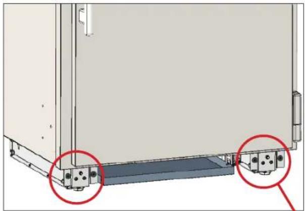
- Place a level on the interior floor on the unit. Check the level back-to-front and side-to-side. See fig. 1 for leveling adjustment locations.
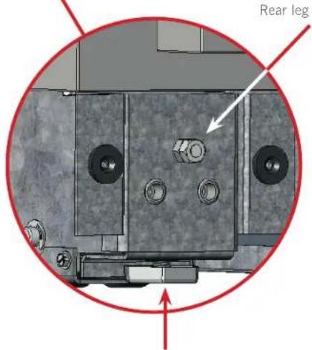
- Adjust the front leveling legs as needed with pliers or an adjustable wrench.
- Adjust the rear leveling legs as needed with a 7/16" socket. Turn clockwise to raise the rear of the unit.
natural_image
Technical diagram of a mechanical assembly with two red circles highlighting specific components (no text or symbols present)FIG. 1. Leveling leg adjustment locations.
Front leg adjustment
INSTALLATION
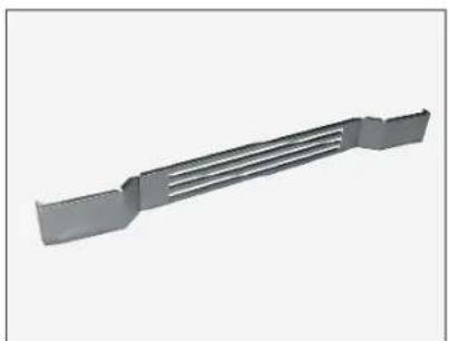
KICKPLATE INSTALLATION
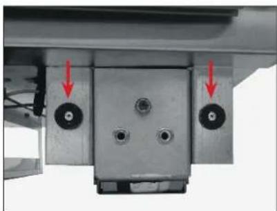
The kickplate (see fig. 1) is shipped unattached to the unit to allow easy access for leveling the unit. The kickplate attaches to the unit with magnets (see fig. 2) located on either side at the bottom of the unit.
INSTALLATION
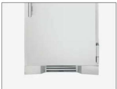
After leveling the unit, position the kickplate at the bottom of the unit's front. See fig. 3.
REMOVAL
Pull the kickplate away from the unit.
natural_image
3D rendering of a gray metal bracket with ribbed top and flange (no text or symbols)FIG. 1. The kickplate.
natural_image
Mechanical assembly with two circular components and red arrows indicating direction (no text or symbols)FIG. 2. The magnets. One side shown.
natural_image
Minimalist abstract view of a white wall with a small rectangular base and vertical lines, no text or symbols present.FIG. 3. Installed kickplate.
INSTALLATION
JOINING KIT INSTALLATION
Kit Sizes: 60" (1524 mm) / 72" (1828.8 mm) / 78" (1981.2 mm) / 90" (2286 mm)
KIT CONTENTS
• (1) Joining Rainshield Assembly
• (1) Joining Kickplate
• Anti-Sweat Foam End Panels*
- Joining Bracket*
• 1/4-20 x 1" Hex Head Screws*
• 1/4" Split Lock Washers*
*Quantities vary by kit size.
REQUIRED TOOLS
Required tools include (but may not be limited to) the following:
• Phillips Bit Driver or Screwdriver
- 7/16" Socket Wrench
• 1/4" Socket Wrench
- Tape
- Marking Utensil
- Drill
NOTE: MAKE SURE THE ANTI-TIP BRACKETS ARE INSTALLED PER INSTALLATION MANUAL INSTRUCTIONS. EACH UNIT WILL ALSO NEED TO BE PROPERLY LEVELED PER INSTALLATION MANUAL INSTRUCTIONS.

CAUTION! Electrical shock or burn hazard. Unplug the unit or turn off the power supply before proceeding.

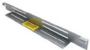
WARNING! To avoid hazards from appliance instability, be sure to install the anti-tip brackets (see fig. 1) on each individual unit per the installation manual
instructions.

WARNING! TIP OVER HAZARD. A child or adult could tip the appliance, resulting in property damage or bodily harm. Follow these instructions to properly install
the anti-tip device. If the appliance is moved, verify that the device is properly engaged before the normal usage of the appliance commences.
natural_image
Metallic metal bracket with a yellow warning label (no text or symbols on the structure itself)FIG. 1. Anti-tip bracket. Be sure to install a bracket for each unit.
natural_image
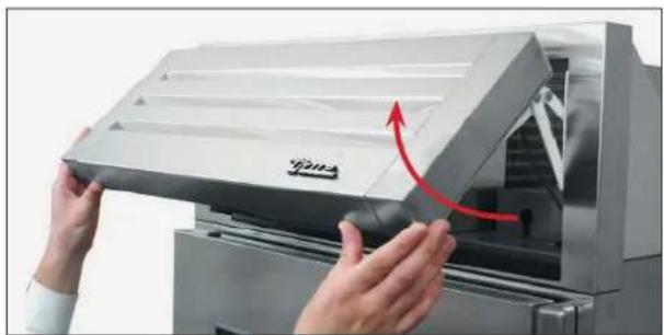
Close-up of hands installing or adjusting a white industrial air conditioner cover with a red arrow indicating motion (no text or symbols visible)FIG. 2. Pull the rainshield open.
natural_image
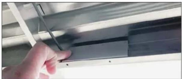
Close-up of a hand adjusting a metallic panel or fixture component (no visible text or symbols)FIG. 3. Locate the reed switch in the bottom of the rainshield.
natural_image
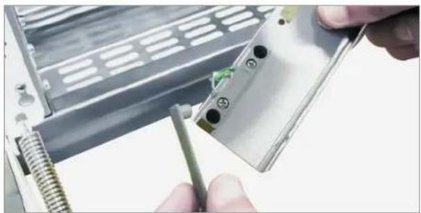
Close-up of hands installing a component into an electronic device (no visible text or symbols)FIG. 4. Remove the plastic cover.
INSTALLATION
JOINING KIT INSTALLATION (CONT.)
Kit Sizes: 60" (1524 mm) / 72" (1828.8 mm) / 78" (1981.2 mm) / 90" (2286 mm)
PROCEDURE
- Remove the reed switch bracket. See figs. 2 and 3.
- Remove the reed switch cover, and then disconnect the reed switch. See figs. 4 and 5.

NOTE: IF FOUR (4) WIRES ARE CONNECTED TO THE REED SWITCH, BE SURE TO CLEARLY LABEL THE WIRES' ORIGINAL LOCATIONS BEFORE DISCONNECTING THE REED SWITCH. WIRE LOCATION IS CRITICAL TO THE CABINET'S OPERATION. SEE FIG. 5.
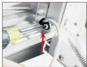
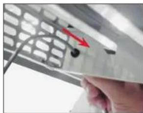
- Remove the reed switch wire from the rainshield. See figs. 6 and 7.
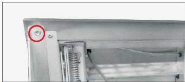
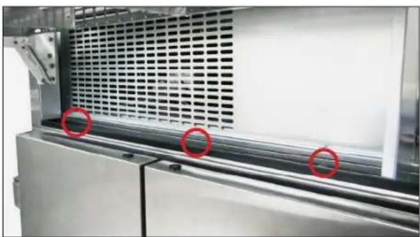
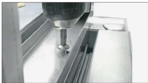
- Remove the rainshield. See figs. 8-10.
- Repeat steps 1-4 for each unit of the joined installation.
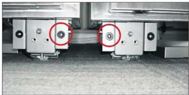
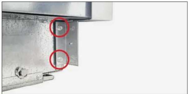
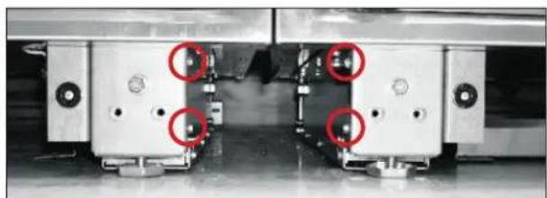
- Remove the inner magnet brackets (see figs. 11 and 12). Then, thread and tighten the magnet bracket screws. Discard the magnet bracket.
NOTE: BE SURE TO RETURN MAGNET BRACKET SCREWS TO THEIR ORIGINAL POSITIONS; THE SCREWS SUPPORT THE CASTOR ASSEMBLY HOUSING.
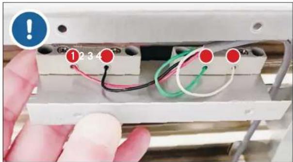
FIG. 5. Label the original wire locations BEFORE disconnecting the reed switch.
natural_image
Close-up of a mechanical device with a black connector and red arrow indicating motion (no visible text or symbols)FIG. 6. Remove the p-clip holding the wire to the rainshield.
natural_image
Close-up of a hand holding a metallic object with a red arrow pointing to a small black object, no visible text or symbols.FIG. 7. Pull the reed switch wire through the rainshield bushing.
natural_image
Close-up of a mechanical component with a red circular mark and spring, no visible text or symbolsFIG. 8. Bracket screw location. Other bracket not shown.
natural_image
Industrial machine with ventilation grilles and three red-circled features on the side (no visible text or symbols)FIG. 9. Rainshield screw locations.
natural_image
Close-up of a precision tool in operation, showing a mechanical component and surrounding compartments (no visible text or symbols)FIG. 10. Remove the screws from the metal channel.
INSTALLATION
JOINING KIT INSTALLATION (CONT.)
Kit Sizes: 60" (1524 mm) / 72" (1828.8 mm) / 78" (1981.2 mm) / 90" (2286 mm)
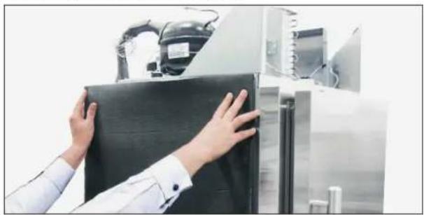
- Install anti-sweat foam end panels on the joined units' sides where the cabinets will meet. See figs. 13 and 14.
- Position the units in front of the final installation location. Then, level the units.
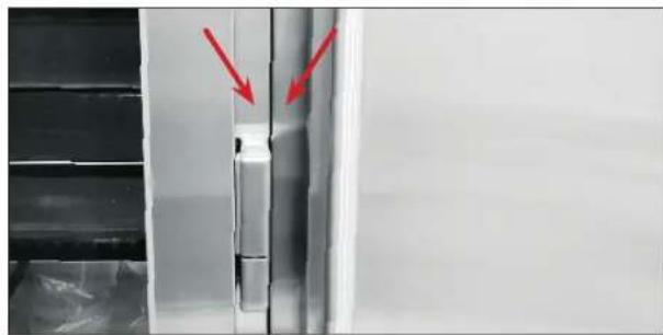
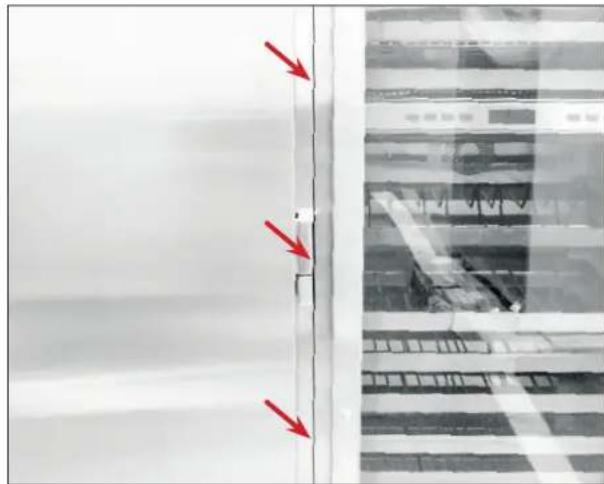
- Verify the fronts of the units are flush at the seams and the gap(s) between the units is (are) consistent from top to bottom. See figs. 15 and 16.
- With the provided hardware, install the joining bracket across the interior legs. See figs. 17 and 18.
- With the existing hardware, install the joining rainshield assembly. See fig. 19.
NOTE: ASSISTANCE (AT LEAST TWO (2) PEOPLE) RECOMMENDED.
- Route the reed switch wires through the rainshield. See figs. 6 and 7.
- With the predrilled holes in the joining rainshield, connect and install the reed switches near the handle-side of the units.

NOTE: BE SURE TO CONNECT THE WIRES TO THE REED SWITCH AS ORIGINALLY CONFIGURED. WIRE LOCATION IS CRITICAL TO THE CABINET'S OPERATION.
SEE FIGS. 5 OR 20.
natural_image
Close-up of mechanical components with red circles highlighting features, no visible text or symbolsFIG. 11. Remove and discard the interior magnet brackets.
natural_image
Close-up of a metallic structural joint with two red-circled features, no visible text or symbolsFIG. 12. Magnet bracket screw locations.
natural_image
Person in lab coat handling a black rectangular object with robotic arm in background (no visible text or symbols)FIG. 13. Install the anti-sweat foam panel where the unit will be positioned next to another unit.
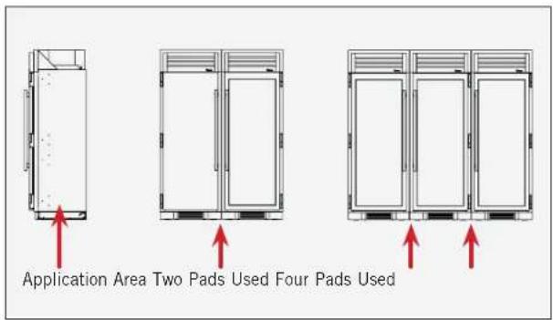
FIG. 14. Install foam pads between the joined units.
INSTALLATION
JOINING KIT INSTALLATION (CONT.)
Kit Sizes: 60" (1524 mm) / 72" (1828.8 mm) / 78" (1981.2 mm) / 90" (2286 mm)
- Walk the joined units into their final installation location.
- Verify the level of the cabinets. Level the units as needed.
- Restore power to the units and turn the units on.
-
After 3 minutes of runtime, open the doors individually and verify correct door switch operation. When operating correctly, the following should occur:
-
Unless set otherwise, the lights turn on and off with the door openings.
- The evaporator (interior) fan turns on and off with door openings.
-
There is a low-pitched click from the control board area when the door opens or shuts.
-
Install the joining kit grill.
natural_image
Close-up of a metallic door with red arrows pointing to the side panel (no text or symbols visible)FIG. 15. Verify the cabinet fronts are flush. Adjust the units accordingly.
natural_image
Exterior view of a modern building with glass panels and red arrows indicating direction (no signage or text)FIG. 16. Verify the gap(s) between cabinets is (are) even throughout.
natural_image
Close-up of mechanical components with four red-circled features, no visible text or symbolsFIG. 17. Return the magnet bracket screws to their original locations
natural_image
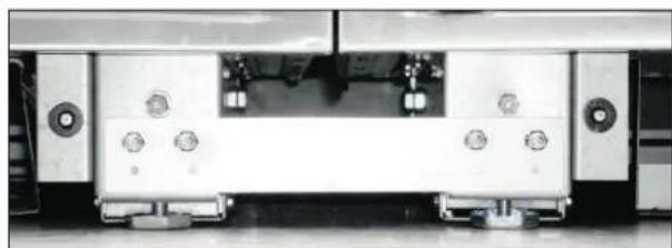
Front view of a white electronic device with multiple ports and control buttons (no visible text or symbols)FIG. 18. Installed joining bracket.
natural_image
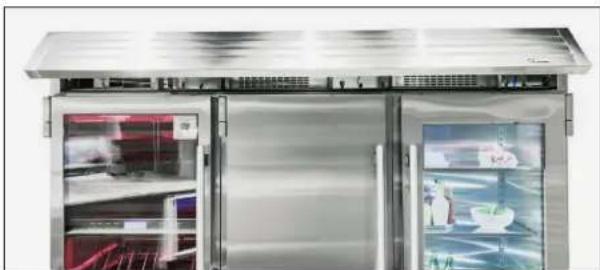
Exterior view of a modern stainless steel double-door refrigerator with open doors showing interior shelves (no visible text or symbols)FIG. 19. Installed joining rainshield.
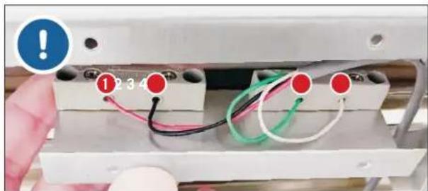
FIG. 20. Connect the reed switches with the original wire configurations.
TEC_TM_009 | REV. I | EN 03/21/2023 Page 39 of 76
TR-30/36 INSTALL MANUAL
NOTES
CABINET SETUP
SHELVING, BINS, DRAWERS
REFRIGERATOR STORAGE
DOOR BINS
DRAWERS
FREEZER STORAGE
WIRE BASKET
OPTIONAL ICEMAKER

PRESERVE THE MOMENT®
CABINET SETUP
SHELVING, BINS, DRAWERS
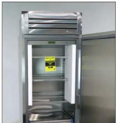
Your TRUE appliance ships with shelving and drawers installed. Door bins ship packaged inside the unit. See fig. 1.
This appliance meets the IEC shelf weight capacity of 47 lb/ft ^2 (230 kg/m ^2 ).
REFRIGERATOR STORAGE
GLASS SHELVES
Remove interior packaging before use. See fig. 2.
ADJUSTMENT
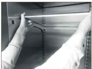
- Tilt the shelf front forward. See fig. 3.
- Lift the shelf up and out of the unit.
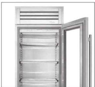
- Hook the shelf into the desired shelf standard slots. See fig. 4.
natural_image
Interior view of a stainless steel refrigerator with open doors and a yellow sticker on the front (no visible text or symbols)FIG. 1. Interior packaging.
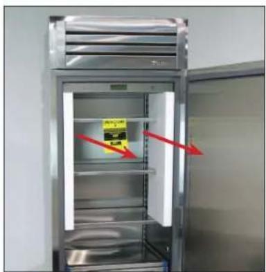
FIG. 2. Remove interior packaging from shelving.
natural_image
Person in lab coat handling a metal shelf with a tool, no visible text or symbolsFIG. 3. Hook the shelves into the shelf standards.
natural_image
Exterior view of a modern stainless steel refrigerator with open door (no signage or text visible)FIG. 4. Installed shelving.
CABINET SETUP
DOOR BINS
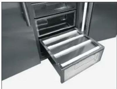
Door bins ship in the refrigerator's bottom drawer. See fig. 5.
INSTALLATION
- Hook a door bin into the door slots. See fig. 6.
- Push the bin down to ensure the tabs are fully engaged in the slots. See fig. 7.
CAUTION! INCORRECTLY INSTALLED DOOR BINS MAY RESULT IN APPLIANCE DAMAGE OR PERSONAL INJURY.
REMOVAL
Lift the door bin up and away from the door.
natural_image
Interior view of a stainless steel refrigerator with open door and drawer (no text or symbols visible)FIG. 5. Packaged door bins.
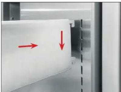
natural_image
Close-up of a white panel with red arrows pointing to a side panel, no visible text or symbolsFIG. 6. Hook the door bins into the door slots.
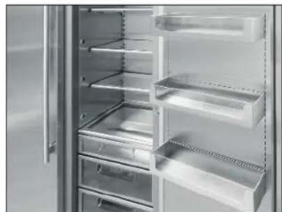
natural_image
Interior view of a refrigerator with open doors and shelves (no visible text or labels)FIG. 7. Final door bin installation.
CABINET SETUP
DRAWERS
REMOVAL
- Pull the drawer fully forward.
- Remove the drawer slide screws. See fig. 8.
- Lift the drawer from the unit.
REMOVAL
- Pull the drawer slides fully forward.
- Position the drawer on the drawer slides and carefully push the drawer towards the back of the unit. Lift the drawer from the unit.
NOTE: BE SURE THE DRAWER SITS UNDER THE SLIDES' REAR TABS. SEE FIG. 9. - Reinstall the drawer slide screws.
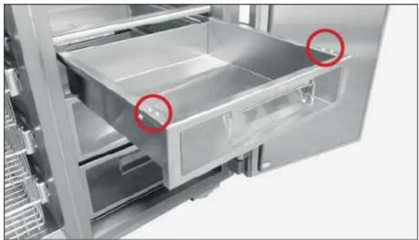
natural_image
Interior view of a stainless steel refrigerator drawer with two red-circled zones highlighting internal compartments (no text or symbols visible)FIG. 8. Drawer slide screw locations.
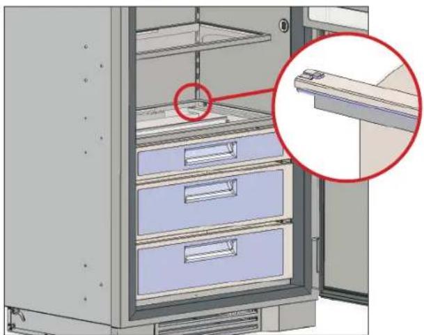
natural_image
3D diagram of a refrigerator with labeled storage compartments and an inset close-up showing a hand holding a shelf (no text or symbols present)FIG. 9. Be sure the drawer sits under the rear tabs.
CABINET SETUP
FREEZER STORAGE
WIRE SHELVES
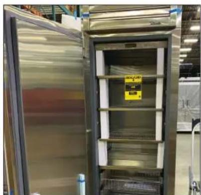
Your TRUE appliance ships with shelving installed. Remove interior packaging before use. See fig. 10.
ADJUSTMENT
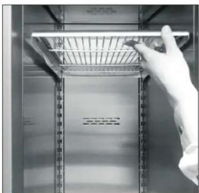
- Tilt the shelf front forward. See fig. 11.
- Lift the shelf up and out of the unit.
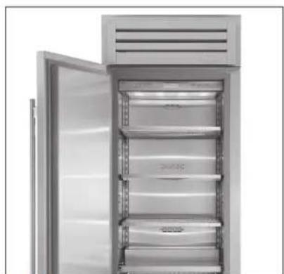
- Hook the shelf into the desired shelf standard slots. See fig. 12.
natural_image
Interior view of a stainless steel laboratory oven with open door and storage compartments (no visible text or labels)FIG. 10. Interior packaging.
natural_image
Close-up of a hand holding a metal rack with a horizontal bar, against a metallic background (no visible text or symbols)FIG. 11. Hook the shelves into the shelf standards.
natural_image
Interior view of a refrigerator with open door and side shelves (no visible text or symbols)FIG. 12. Installed shelving.
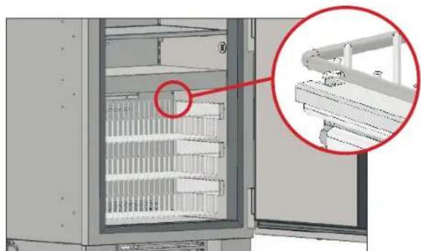
WIRE BASKETS
REMOVAL
- Pull the drawer fully forward.
- Remove the drawer slide screws. See fig. 13.
- Lift the drawer from the unit.
INSTALLATION
- Pull the drawer slides fully forward.
- Position the drawer on the drawer slides and carefully push the drawer towards the back of the unit. NOTE: Be sure the drawer sits under the slides' rear tabs. See fig. 14.
- Reinstall the drawer slide screws.
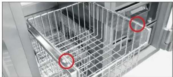
natural_image
Interior view of a stainless steel kitchen appliance with visible mesh structure and two red-circled points (no text or symbols)FIG. 13. Drawer slide screw locations.
natural_image
Interior view of a refrigerator with a red circle highlighting a component, showing internal shelves and structural details (no text or symbols)FIG. 14. Drawer slide screw locations.
CABINET SETUP
OPTIONAL ICEMAKER
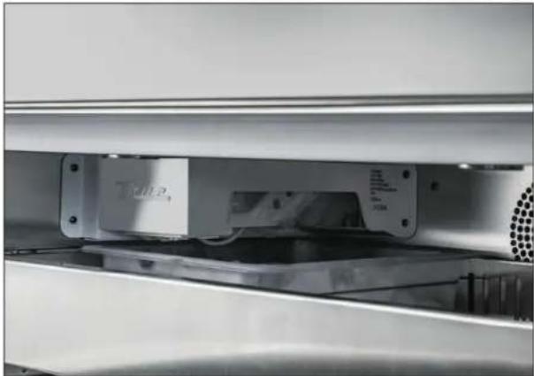
The icemaker (see fig. 1) is in the rear upper left of the freezer section. For water supply requirements, please see "Water Supply Requirements" (page 17). To turn the icemaker on, please see "Ice Menu Navigation" (page 55).
- The icemaker will not operate if the water filter has not been installed. See "Water Filter Installation" (page 18) for installation instructions.
• After the initial startup, discard the first batch of produced ice. This ice may contain impurities from new plumbing connections. - Do not remove the ice bin, even if the icemaker is not in use. The ice bin prevents stacked product from damaging the icemaker.
- If ice is not used regularly, it may fuse together. To avoid this, discard the ice and allow the ice maker to replenish.
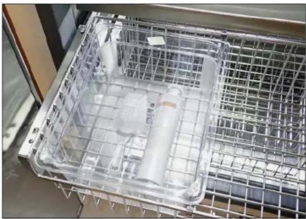
ICE SCOOP
The ice scoop ships inside the ice bin. See fig. 2.
MAX ICE
When the max ice is turned on, the unit maximizes ice production for 24 hours. For information on turning Max Ice on or off, please see "Ice Menu Navigation" (page 55).
natural_image
Close-up of a metallic industrial machine component with no visible text or symbolsFIG. 1. The icemaker.
natural_image
Interior view of a stainless steel kitchen appliance with a transparent rack and plastic container (no visible text or symbols)FIG. 2. The ice scoop ships inside the ice bin.
TEMPERATURE ADJUSTMENT
MODE NAVIGATION
SHOWROOM MODE
ACCENT LIGHTING SYSTEM
ALARM NAVIGATION
NOTIFICATION ALERTS
ICE MENU NAVIGATION (OPTIONAL ICEMAKER ONLY)

PRESERVE THE MOMENT®
All units are shipped in ON mode. During the initial startup, the unit runs a short power up diagnostic followed by a single audible beep. The lights turn on and temperature readings appear on the display.

WARNING! Electrical shock or burn hazard. Turning the unit off with the power button does not remove the power supply from the control. Unplug the unit or turn off the power supply.
PLEASE NOTE THAT THOUGH THE DISPLAY CAN SHOW EITHER FAHRENHEIT OR CELSIUS, IN MOST CASES THE FIGURES SHOW FAHRENHEIT.
TEMPERATURE ADJUSTMENT
- Press down √ or up ∧ until the display shows the desired set point.
NOTE: A BUTTON PRESS CHANGES THE SET POINT BY 1° AND IS ACCOMPANIED BY AN AUDIBLE BEEP.
- When the display shows the desired set point, leave the display inactive until the display shows the Home screen.
| Default Set Point Temperature Range | ||
| Refrigerator Zone | 38°F(3°C) | 34 - 42°F(1 - 6°C) |
| Freezer Zone | 0°F(-18°C) | -4 - 4°F(-20 - -16°C) |
SET POINT NAVIGATION


flowchart
graph LR
    A["True. 38°F"] --> B["OR Gate"]
    B --> C["REFRIGERATOR 38°F"]
    D["No Action (5 sec)"] --> B
REFRIGERATOR 38°F / FREEZER 0°F
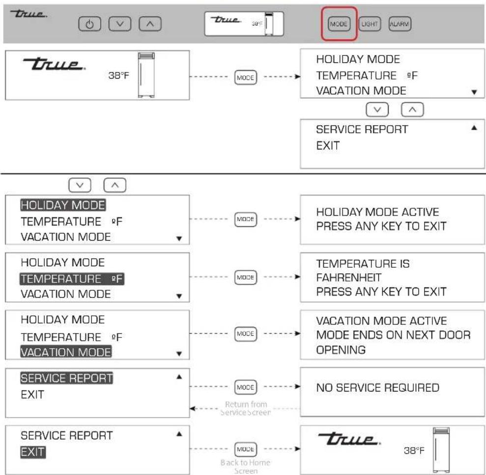
This page explains the following models:
• HOLIDAY Mode
• Temperature Unit Selection Mode
• VACATION MODE
HOLIDAY MODE
NOTE: IN HOLIDAY MODE, SET POINTS CANNOT CHANGE AND MANUAL DEFROST CANNOT INITIATE.
The following holds TRUE in accordance with Star-K requirements:
- Freezer defrosting function switch to a fixed time-based sequence.
- The compartment/zone thermistors detect cut-in and cut-out temperatures (determining factor to start/stop cooling), but there is a random 16-21 second delay before cooling begins/ends.
- The display shows HOLIDAY MODE ACTIVE when the door is closed.
VACATION MODE
Vacation mode is operation optimized for energy savings.
MODE NAVIGATION
flowchart
graph TD
    A["true. 38°F"] --> B["HOLIDAY MODE TEMPERATURE &F VACATION MODE"]
    B --> C["MODE"]
    C --> D["HOLIDAY MODE ACTIVE PRESS ANY KEY TO EXIT"]
    D --> E["HOLIDAY MODE Temperature &F VACATION MODE"]
    E --> F["MODE"]
    F --> G["TEMPERATURE IS FAHRENHEIT PRESS ANY KEY TO EXIT"]
    G --> H["HOLIDAY MODE TEMPERATURE &F VACATION MODE"]
    H --> I["MODE"]
    I --> J["VACATION MODE ACTIVE MODE ENDS ON NEXT DOOR OPENING"]
    J --> K["NO SERVICE REQUIRED"]
    K --> L["SERVICE REPORT EXIT"]
    L --> M["MODE Return from Service Screen"]
    M --> N["Service REPORT EXIT"]
    N --> O["MODE Back to Home Screen"]
    O --> P["true. 38°F"]
SHOWROOM MODE DISABLES THE REFRIGERATION SYSTEM. The appliance will not cool or defrost; however, the lighting system and door ajar alarm system function, and the display shows the set points.
NOTE: ALL MENUS ARE DISPLAY ONLY. ANY SETTING CHANGES WILL NOT AFFECT THE REFRIGERATION SYSTEM'S OPERATION UNTIL SHOWROOM MODE IS OFF.
SHOWROOM MODE ON
- Press both power ⏻ and down ∨ until the display shows the service warning.
- Press down.
- Press down until SHOWROOM MODE OFF is selected.
- With SHOWROOM MODE OFF selected, press MODE.
SHOWROOM MODE OFF
- Press both power ⏻ and down ∨ until the display shows the service warning.
- Press down.
- Press down until SHOWROOM MODE ON is selected.
- With SHOWROOM MODE ON selected, press MODE.
HOME SCREEN
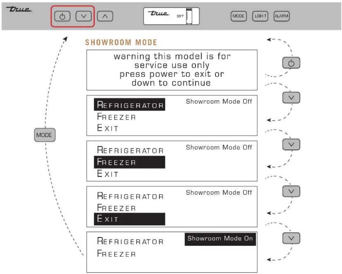
flowchart
graph TD
    A["MODE"] --> B["SHOWROOM MODE"]
    B --> C["Warning this model is for service use only press power to exit or down to continue"]
    C --> D["Refrigerator\nFREEZER\nEXIT"]
    D --> E["Showroom Mode Off"]
    C --> F["Refrigerator\nFREEZER\nEXIT"]
    F --> G["Showroom Mode Off"]
    C --> H["Refrigerator\nFREEZER\nEXIT"]
    H --> I["Showroom Mode Off"]
    C --> J["Refrigerator\nFREEZER\nEXIT"]
    J --> K["Showroom Mode On"]
All models are equipped with an accent lighting system in the refrigerator/freezer compartment(s).
PROCEDURE
- Press LIGHT.
- With the arrow buttons, navigate to the desired menu option.
- With the desired option selected, press LIGHT to toggle between options.
LIGHT MODE: Interior lights
BACKLIGHT: Display
ON mode: Stays illuminated when the door is closed.
NOTE: WHEN IN ON MODE, LIGHTS WILL NOT FADE-UP WHEN THE DOOR OPENS.
DOOR mode: Only illuminates when the door is open.
LIGHT NAVIGATION
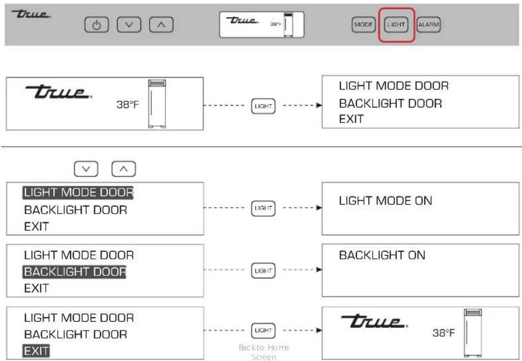
flowchart
graph TD
    A["38°F"] --> B["LIGHT"]
    B --> C["LIGHT MODE DOOR BACKLIGHT DOOR EXIT"]
    D["38°F"] --> E["LIGHT MODE ON"]
    F["38°F"] --> G["Backlight ON"]
    H["38°F"] --> I["Back to Home Screen"]
ALARM NAVIGATION (DOOR AJAR ALARM FEATURE ON/OFF)
All models are equipped with a door ajar alarm. The door ajar alarm beeps continuously when the door is left open for more than 5 minutes. During a door ajar alarm, the display shows the notification icons.
ENABLE:
Press ALARM. The display will show DOOR ALARM IS ON.
DISABLE:
Press ALARM. The display will show DOOR ALARM IS OFF.
ALARM NAVIGATION
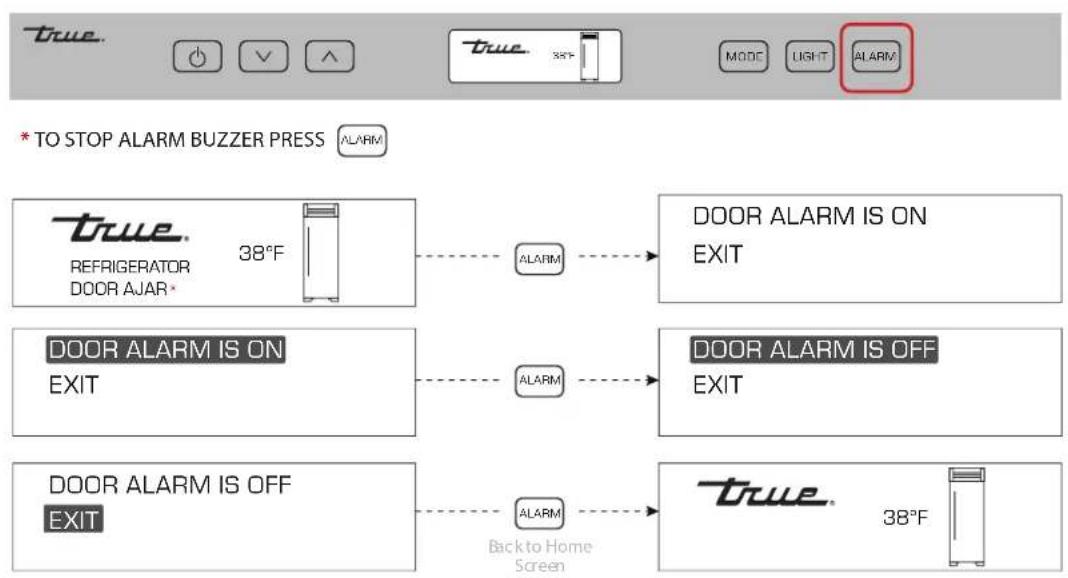
flowchart
graph TD
    A["TO STOP ALARM BUZZER PRESS ALARM"] --> B["REFRIGERATOR DOOR AJAR 38°F"]
    B --> C{ALARM}
    C --> D["DOOR ALARM IS ON EXIT"]
    D --> E["DOOR ALARM IS ON EXIT"]
    E --> F{ALARM}
    F --> G["DOOR ALARM IS OFF EXIT"]
    G --> H{ALARM}
    H --> I["DOOR ALARM IS OFF EXIT"]
    I --> J["Back to Home Screen"]
    J --> K["TRUE 38°F"]
The following notification alerts may show on the display if the appliance needs attention.
NOTIFICATION ALERTS
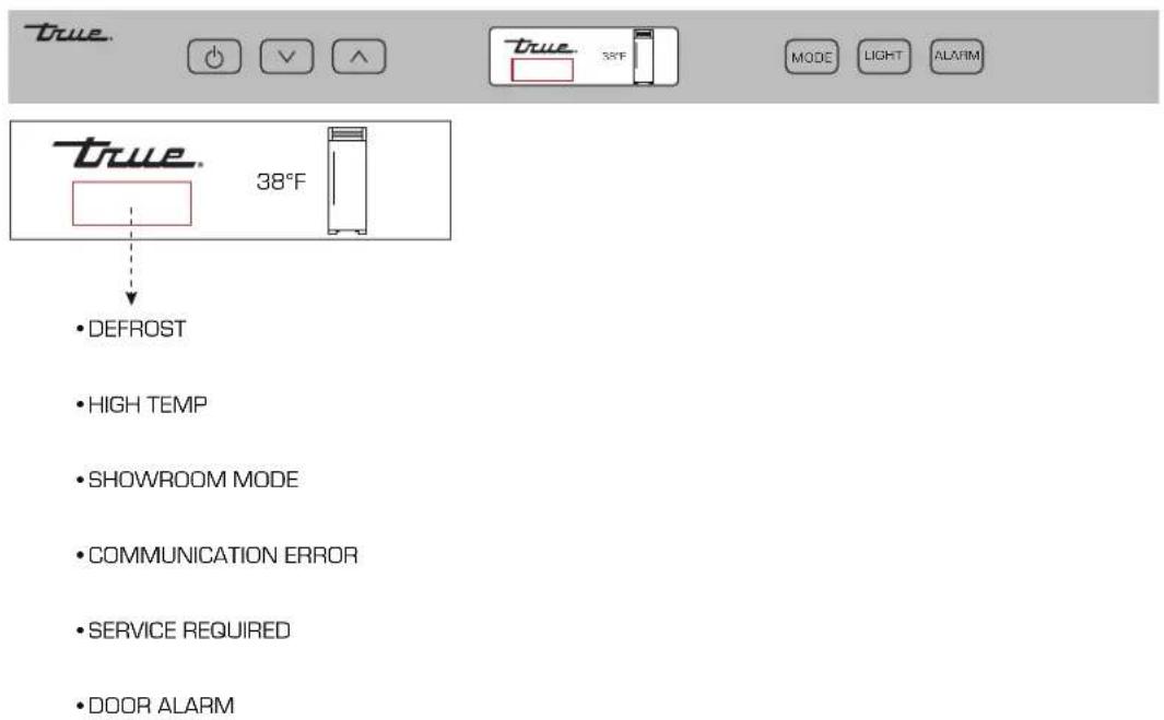
To enter the Ice Menu, press ICE on the user interface. Use the UP and DOWN arrows to navigate between the menu options and use ICE to make a selection. See the diagram below.
The Ice Menu contains three operations.
- Ice Maker: Toggles the icemaker between on/off.
• Max Ice: Maximizes ice production for 24 hours.
• Water Filter Reset: Immediately resets the countdown to change the water filter.
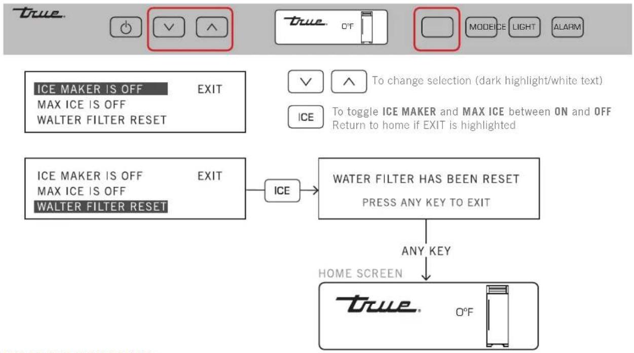
flowchart
graph TD
    A["ICE MAKER IS OFF"] --> B["EXIT"]
    C["MAX ICE IS OFF"] --> B
    D["WALTER FILTER RESET"] --> B
    E["ICE"] --> F["WATER FILTER HAS BEEN RESET"]
    G["MAX ICE IS OFF"] --> F
    H["WALTER FILTER RESET"] --> F
    I["TO change selection (dark highlight/white text)"] --> J["To toggle ICE MAKER and MAX ICE between ON and OFF"]
    K[" return to home if EXIT is highlighted"] --> L["ANY KEY"]
    M["HOME SCREEN"] --> N["TRUE O°F"]
ICE TROUBLESHOOTING
Please see the table below to troubleshoot some common problems with ice production. If your issue is not resolved, please contact TRUE Residential Service at 844-746-9423 or TRUEResidentialService@TRUEMfg.com.
| Icemaker Troubleshooting | |
| No ice | Verify the water filter is installedVerify water is being supplied to the unitVerify the icemaker is on and has been running for at least 24 hoursVerify the ice bin is positioned correctlyVerify the freezer temperature is near 0^ Verify the water filter has been replaced within the last 12 months and has been installed correctly |
| Black flecks in the ice cubes | Stop use and contact TRUE Residential Technical Service |
| Bad taste | Defrost the freezer and clean with soap and waterPlace coffee grounds or charcoal briquettes in the freezer to absorb odor |
| Hollow cubes | Clean the condenser coil. Contact TRUE Residential Customer Service if the issue is unresolved. |
NOTES
DUAL ZONE OPERATION
NOTE: AN ELECTRONIC CONTROL DISPLAY MAY REFLECT THE FLUCTUATING TEMPERATURES OF THE REFRIGERATION CYCLE, NOT THE PRODUCT TEMPERATURE. THE MOST ACCURATE METHOD TO DETERMINE AN APPLIANCE'S OPERATION IS TO VERIFY THE PRODUCT TEMPERATURE.
All units are shipped in ON mode. During the initial startup, the unit runs a short power up diagnostic followed by a single audible beep. The lights turn on and temperature readings appear on the display.

WARNING! Electrical shock or burn hazard. Turning the unit off with the power button does not remove the power supply from the control. Unplug the unit or turn off the power supply.
PLEASE NOTE THAT THOUGH THE DISPLAY CAN SHOW EITHER FAHRENHEIT OR CELSIUS, IN MOST CASES THE FIGURES SHOW FAHRENHEIT.
DUAL ZONE OPERATION
TEMPERATURE ADJUSTMENT
- Press ZONE until the display selects the desired zone.
- Press down √ or up ∧ until the display shows the desired set point.
NOTE: A BUTTON PRESS CHANGES THE SET POINT BY 1° AND IS ACCOMPANIED BY AN AUDIBLE BEEP.
- When the display shows the desired set point, press ZONE or leave the display inactive until the display shows the Home screen.
| Default Set Point Temperature Range | ||
| Upper Zone | 55°F(12.7°C) | 40 - 65°F(4.4 - 18.3°C) |
| Lower Zone | 45°F(7.2°C) | 40 - 65°F(4.4 - 18.3°C) |
SET POINT NAVIGATION
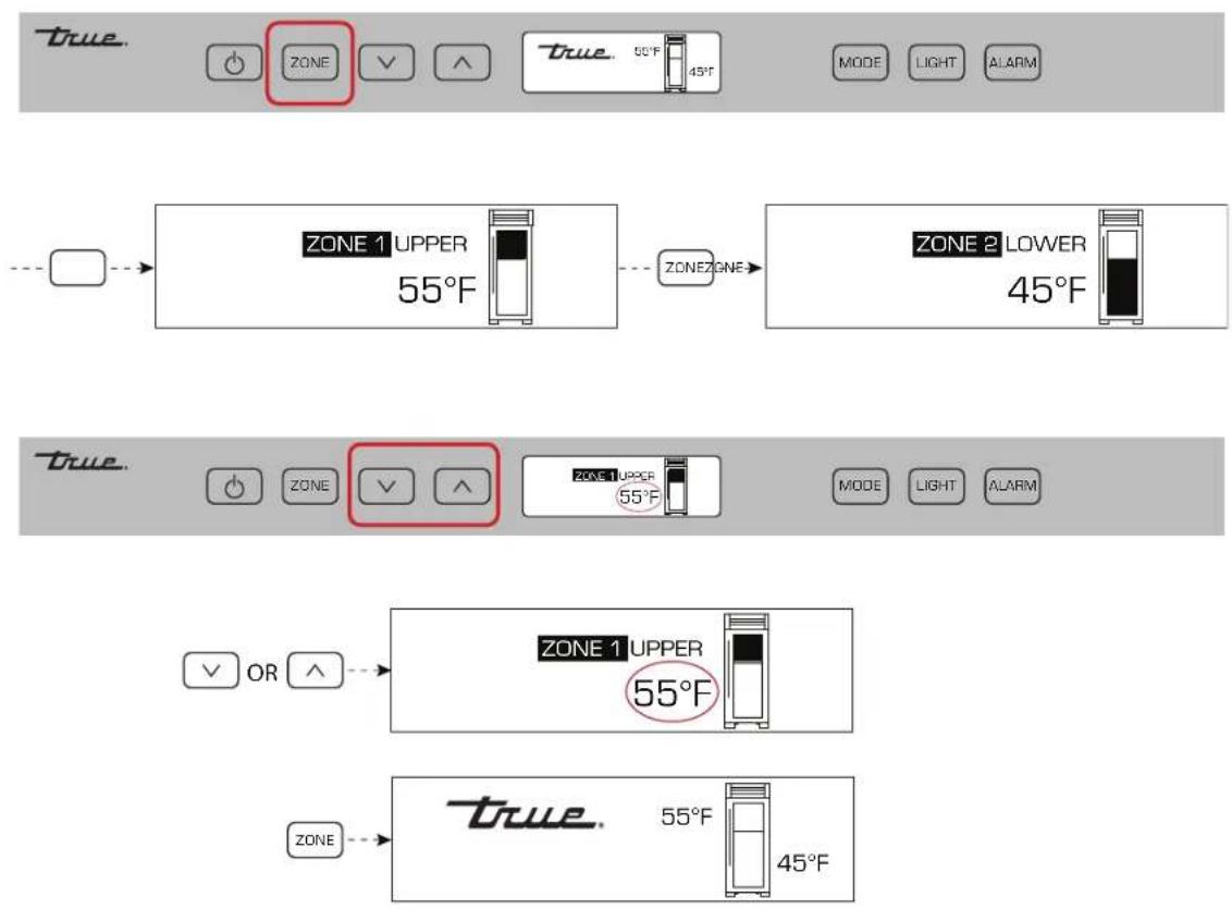
This page explains the following models:
• HOLIDAY Mode
• Temperature Unit Selection Mode
• VACATION MODE
HOLIDAY MODE
NOTE: IN HOLIDAY MODE, SET POINTS CANNOT CHANGE AND MANUAL DEFROST CANNOT INITIATE.
The following holds TRUE in accordance with Star-K requirements:
- Freezer defrosting function switch to a fixed time-based sequence.
- The compartment/zone thermistors detect cut-in and cut-out temperatures (determining factor to start/stop cooling), but there is a random 16-21 second delay before cooling begins/ends.
- The display shows HOLIDAY MODE ACTIVE when the door is closed.
VACATION MODE
Vacation mode is operation optimized for energy savings.
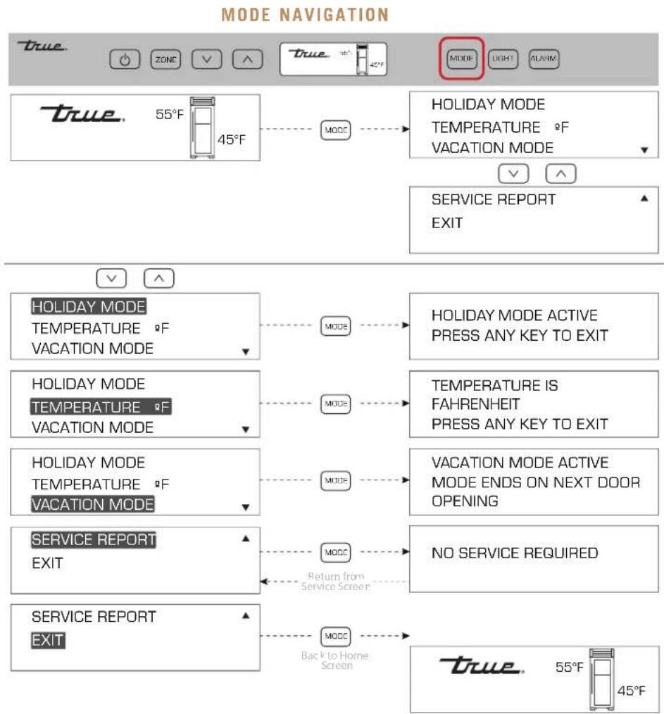
PAGE TITLE
SHOWROOM MODE
SHOWROOM MODE DISABLES THE REFRIGERATION SYSTEM. The appliance will not cool or defrost; however, the lighting system and door ajar alarm system function, and the display shows the set points.
NOTE: ALL MENUS ARE DISPLAY ONLY. ANY SETTING CHANGES WILL NOT AFFECT THE REFRIGERATION SYSTEM'S OPERATION UNTIL SHOWROOM MODE IS OFF.
SHOWROOM MODE ON
- Press both power ⏻ and down ∨ until the display shows the service warning.
- Press down.
- Press down until SHOWROOM MODE OFF is selected.
- With SHOWROOM MODE OFF selected, press MODE.
SHOWROOM MODE OFF
- Press both power ⏻ and down ∨ until the display shows the service warning.
- Press down.
- Press down until SHOWROOM MODE ON is selected.
- With SHOWROOM MODE ON selected, press MODE.
HOME SCREEN

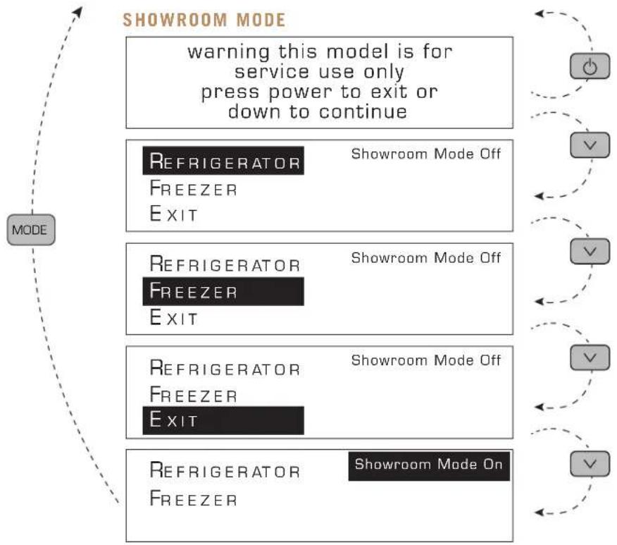
flowchart
graph TD
    A["MODE"] --> B["Warning this model is for service use only press power to exit or down to continue"]
    B --> C["Refrigerator FREEZER EXIT"]
    C --> D["Showroom Mode Off"]
    C --> E["Refrigerator FREEZER EXIT"]
    E --> F["Showroom Mode Off"]
    E --> G["Refrigerator FREEZER EXIT"]
    G --> H["Showroom Mode Off"]
    G --> I["Refrigerator FREEZER"]
    I --> J["Showroom Mode On"]
DUAL ZONE OPERATION
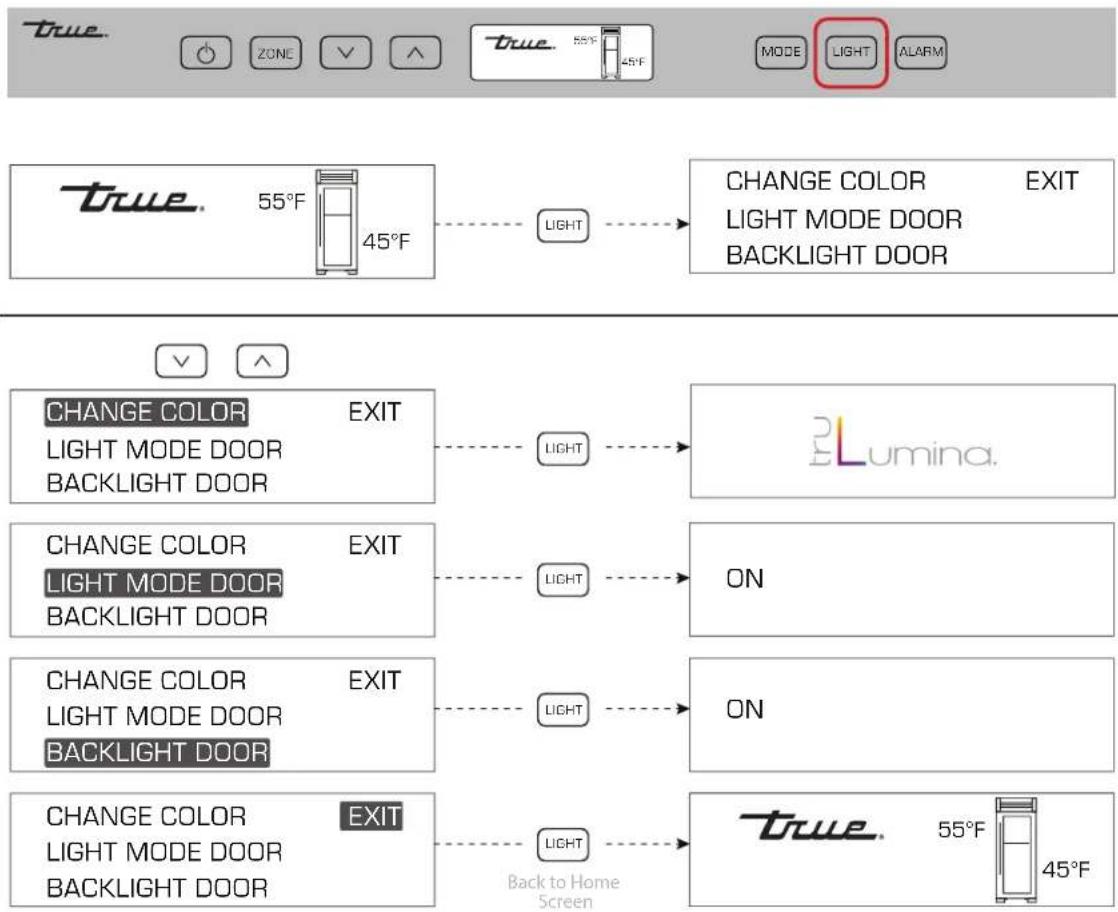
ACCENT LIGHTING SYSTEM CHANGE TRULUMINA
® LIGHT COLOR
All models are equipped with an accent lighting system in the refrigerator/freezer compartment(s).
PROCEDURE
- Press LIGHT
- With the arrow buttons, navigate to the desired menu option.
- With the desired option selected, press LIGHT to toggle between options.
LIGHT MODE: Interior lights
BACKLIGHT: Display
ON mode: Stays illuminated when the door is closed.
NOTE: WHEN IN ON MODE, LIGHTS WILL NOT FADE-UP WHEN THE DOOR OPENS.
DOOR mode: Only illuminates when the door is open.
PROCEDURE
- Press LIGHT until the display shows CHANGE COLOR.
- With the display showing CHANGE COLOR, press LIGHT. The appliance will cycle through the light color options.
- When the light is the desired color, press LIGHT.
trD Lumina.
LIGHT NAVIGATION
DUAL ZONE OPERATION
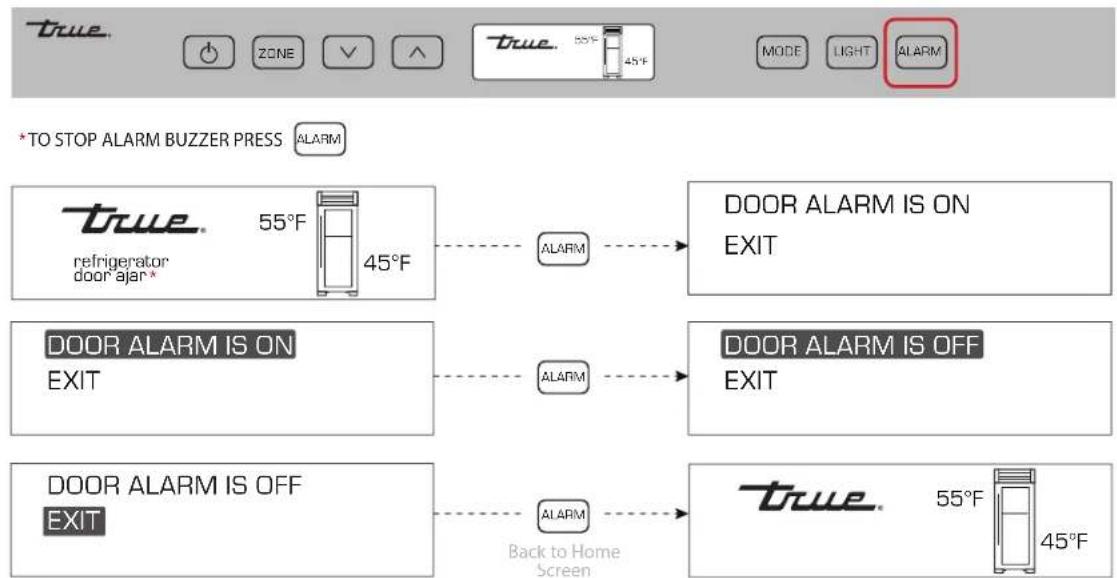
ALARM NAVIGATION (DOOR AJAR ALARM FEATURE ON/OFF)
All models are equipped with a door ajar alarm. The door ajar alarm beeps continuously when the door is left open for more than 5 minutes. During a door ajar alarm, the display shows the notification icons.
ENABLE:
Press ALARM. The display will show DOOR ALARM IS ON.
DISABLE:
Press ALARM. The display will show DOOR ALARM IS OFF.
ALARM NAVIGATION
flowchart
graph TD
    A["TO STOP ALARM BUZZER PRESS ALARM"] --> B["refrigerator 55°F door ajar*"]
    B --> C["ALARM"] --> D["DOOR ALARM IS ON EXIT"]
    E["DOOR ALARM IS ON EXIT"] --> F["ALARM"] --> G["DOOR ALARM IS OFF EXIT"]
    H["DOOR ALARM IS OFF EXIT"] --> I["ALARM"] --> J["true 55°F 45°F"]
    J --> K["Back to Home Screen"]
DUAL ZONE OPERATION
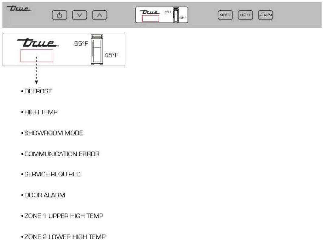
NOTIFICATION ALERTS
The following notification alerts may show on the display if the appliance needs attention.
NOTIFICATION ALERTS
MAINTENANCE, CARE & CLEANING
INTERIOR ACCESSORIES
DOOR REMOVAL
CONDENSER COIL CLEANING
CONDENSATION
HANDLE TIGHTENING
WATER FILTER REPLACEMENT
STAINLESS STEEL EQUIPMENT CARE AND CLEANING
SERIAL LABEL LOCATION
CONTACT US
WARRANTY

PRESERVE THE MOMENT®
MAINTENANCE, CARE & CLEANING
INTERIOR ACCESSORIES
All removable interior accessories are dishwasher safe.
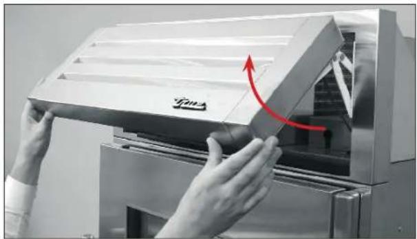
DOOR REMOVAL
REMOVAL
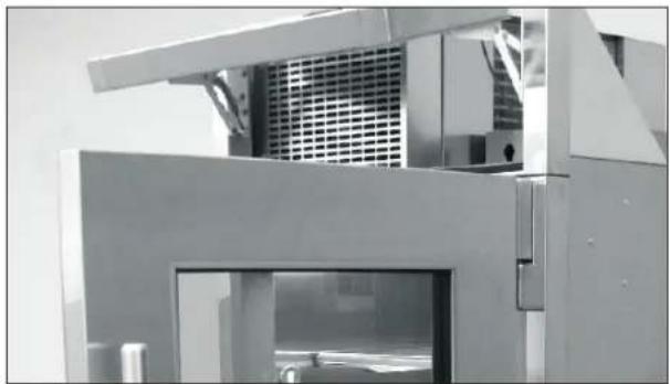
- Open the rainshield. See fig. 1.
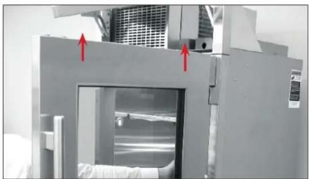
- Open the door 90°. See fig. 2.
- Carefully lift the door from the hinges. See fig. 3
INSTALLATION
- Open the rainshield. See fig. 1.
- Hold the door 90° to the opening.
- Align the hinge posts with the hinges.
- Lower the door into place.
natural_image
Close-up of hands installing a metal door frame with a red arrow indicating rotation (no text or symbols visible)FIG. 1. Open the rainshield.
natural_image
Industrial machinery component with metallic frame and ventilation grating (no visible text or symbols)FIG. 2. Open the door 90^ .
natural_image
Industrial machine with red arrows pointing to a window or vent, no visible text or symbolsFIG. 3. Lift the door up.
GENERAL MAINTENANCE, CARE & CLEANING
CONDENSER COIL CLEANING
Keeping the condenser coil clean minimizes required servicing and lowers electrical cost. Warranty does not cover cleaning the condenser coil.

WARNING! Electrical shock or burn hazard. Unplug the unit or turn off the power supply before proceeding. DO NOT clean appliance with a pressure washer or hose.

CAUTION! Risk of eye injury from debris. Eye protection is recommended.

CAUTION! Coil fins are sharp. Gloves are recommended.
REQUIRED TOOLS
- Stiff-bristled brush
• Vacuum Cleaner - Gloves (recommended)
PROCEDURE
- Open the rainshield. See fig. 1.
- With a stiff-bristled brush, carefully clean accumulated dirt from the condenser coil fins. See fig. 2.
NOTE: NEVER BRUSH ACROSS THE COIL FINS.
-
Carefully vacuum any dirt around the condensing unit area.
-
Close the rainshield.
CONDENSATION
Leaving the doors and/or drawers open for long periods of time or running a unit with little/no product inside may cause excessive condensation.
HANDLE TIGHTENING
Tighten handles with a 3/32" Allen wrench.
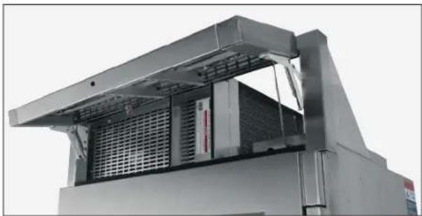
natural_image
Exterior view of a stainless steel industrial machine with ventilation grilles and cooling fins (no visible text or symbols)FIG. 1. Opened rainshield.
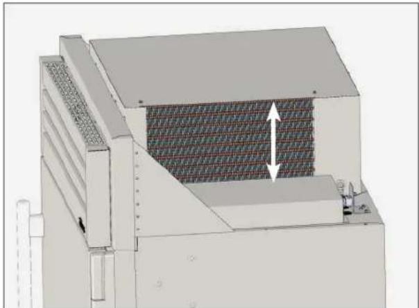
natural_image
3D technical illustration of a mechanical or industrial device with a meshed panel and directional arrow (no text or symbols)FIG. 2. Never brush across coil fins.
GENERAL MAINTENANCE, CARE & CLEANING
WATER FILTER REPLACEMENT (OPTIONAL ICEMAKER ONLY)
The ice machine water has a life expectancy of 300 gal (1,136 L) or six months. When the water filter reaches the end of its life, the control display shows WATER FILTER.
To order a replacement water filter, go to https://store. TRUEresidential.com/collections/maintenance-1 or contact our parts department at 844-849-6226 or TRUEResidentialParts@TRUEMfg.com.
Follow the instruction below to change the water filter. For information on clearing the water filter notification, please see "Ice Menu Navigation" (page 55).
PROCEDURE
- Remove the kickplate. See fig. 1.
- Rotate the water filter counterclockwise and pull the filter from the unit. See fig. 2.
- Insert the replacement water filter and rotate the filter clockwise. See fig. 3.
- Reinstall the kickplate.
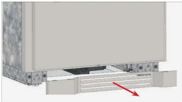
natural_image
3D diagram of a mechanical assembly with a red arrow indicating a directional component (no text or symbols present)FIG. 1. Pull the kickplate from the cabinet.
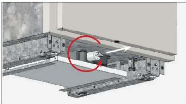
natural_image
Technical diagram of a mechanical assembly with a red circle highlighting a component, no visible text or symbolsFIG. 2. Rotate the existing water filter counterclockwise.
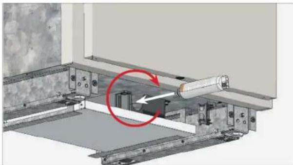
natural_image
Mechanical assembly diagram showing a rotating shaft mounted on a metal frame with a red circular arrow indicating motion (no text or symbols present)FIG. 3. Insert the new water filter and rotate it clockwise.
STAINLESS STEEL EQUIPMENT CARE AND CLEANING

NOTE! DO NOT USE ANY STEEL WOOL, ABRASIVE OR CHLORINE BASED PRODUCTS TO CLEAN STAINLESS STEEL SURFACES.
STAINLESS STEEL OPPONENTS
There are three basic things which can break down your stainless steel's passivity layer and allow corrosion to rear its ugly head.
- Scratches from wire brushes, scrapers, and steel pads are just a few examples of items that can be abrasive to stainless steel's surface.
- Deposits left on your stainless steel can leave spots. You may have hard or soft water depending on what part of the country you live in. Hard water can leave spots. Hard water that is heated can leave deposits if left to sit too long. These deposits can cause the passive layer to break down and rust your stainless steel. All deposits left from food prep or service should be removed as soon as possible.
- Chlorides are present in table salt, food, and water. Household and industrial cleaners are the worst type of chlorides to use.
STAINLESS STEEL CLEANING AND RESTORATION
Do not use stainless steel cleaners or similar solvents to clean plastic or powder-coated parts. Instead, use warm soapy water.
- For routine cleaning and removal of grease and oil, apply white vinegar, ammonia, or any good commercial detergent* with a soft cloth or sponge.
- Stainless steel polish (i.e., Zep® Stainless Steel Polish, Weiman® Stainless Steel Cleaner & Polish, Nyco® Stainless Steel Cleaner & Polish, or Ecolab® Ecoshine®) and olive oil can act as a barrier against fingerprints and smears.
- Degreasers* (i.e., Easy-Off ® Specialty Kitchen Degreaser or Simple Green® Industrial Cleaner & Degreaser) are excellent for removal of grease, fatty acids, blood and burnt-on foods on all surfaces.
- For restoration/passivation or removing stubborn stains and discoloration, Brillo ^® Cameo ^® , Zud ^® Cleanser, Ecolab ^® Specifax ^™ First Impression ^® Metal Polish, Sheila Shine, or talc can be applied by rubbing in the direction of the polish lines.
* DO NOT USE DETERGENTS OR DEGREASERS WITH CHLORIDES OR PHOSPHATES.
MAINTENANCE, CARE & CLEANING
STAINLESS STEEL EQUIPMENT CARE AND CLEANING
8 TIPS TO HELP PREVENT RUST ON STAINLESS STEEL
- Maintain the Cleanliness of Your Equipment – Avoid build-up of hard stains by cleaning frequently. Use cleaners at the recommended strength (alkaline chlorinated or non-chloride).
- Use the Correct Cleaning Tools – Use non-abrasive tools when cleaning your stainless steel products. The stainless steel's passive layer will not be harmed by soft cloths and plastic scouring pads.
- Clean Along Polishing Lines – Polishing lines ("grain") are visible on some stainless steels. Always scrub parallel to polishing lines when visible. Use a plastic scouring pad or soft cloth when you cannot see the grain.
• Use Alkaline, Alkaline-Chlorinated or Non-Chloride
Cleaners – While many traditional cleaners are loaded with chlorides, the industry is providing an ever increasing choice of non-chloride cleaners. If you are not sure of your cleaner's chloride content, contact your cleaner supplier. If they tell you that your present cleaner contains chlorides, ask if they have an alternative. Avoid cleaners containing quaternary salts, as they can attack stainless steel, causing pitting and rusting.
- Rinse – When using chlorinated cleaners, you must rinse and wipe dry immediately. It is better to wipe standing cleaning agents and water as soon as possible. Allow the stainless steel equipment to air dry. Oxygen helps maintain the passivity film on stainless steel.
• Never Use Hydrochloric Acid (Muriatic Acid) on
Stainless Steel – Even diluted, hydrochloric acid can cause corrosion, pitting and stress corrosion cracking of stainless steel.
- Water Treatment – To reduce deposits, soften hard water when possible. Installation of certain filters can remove corrosive and distasteful elements.
Salts in a properly maintained water softener can also be to your advantage. Contact a treatment specialist if you are not sure of the proper water treatment.
• Regularly Restore & Passivate Stainless Steel –
Stainless steel gets its stainless properties from the protective chromium oxides on its surface. If these oxides are removed by scouring, or by reaction with harmful chemicals, then the iron in the steel is exposed and can begin to oxidize, or rust. Passivation is a chemical process that removes free iron and other contaminants from the surface of stainless steel, allowing the protective chromium oxides to re-form.
GENERAL MAINTENANCE, CARE & CLEANING
COMPONENT REPLACEMENT
- Replace components with original equipment manufacturer (OEM) components. OEM parts minimize the risk of possible ignition due to incorrect parts. Use of non-OEM components may void TRUE's warranty.
- Have a licensed service provider service your unit to minimize the risk of possible ignition due to incorrect parts or improper service and to ensure the operator's health and safety.
SERIAL LABEL LOCATION
The serial label is located on the left wall near the freezer wire basket or the refrigerator upper drawer.
This label contains important information such as your model name and serial number. Please have this information on hand when contacting TRUE so we can better assist you with your service -or parts- related inquiries.
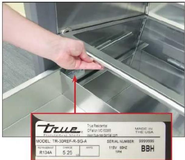
FIG. 1. Serial label location.
CONTACT US
CUSTOMER SERVICE
Phone: 888-616-8783
info@true-residential.com
WARRANTY DEPARTMENT
Phone: 844-849-6179
trueresidentialwarranty@truemfg.com
SERVICE DEPARTMENT
Phone: 844-746-9423
trueresidentialservice@truemfg.com
NOTES
NOTES
NOTES
TRUE RESIDENTIAL® SERIES LIMITED WARRANTY STATEMENT
LIMITED 30 DAY COSMETIC WARRANTY
Stainless steel doors, handles, and shelves are warranted to be free from defective materials or workmanship for a period of thirty (30) days from the date of original retail purchase. Any defects must be reported to the selling dealer within thirty (30) days from the date of original retail purchase. This limited warranty excludes any type of freight / concealed damage.
THREE-YEAR PARTS & LABOR WARRANTY \*For units purchased after Feb 1, 2013
TRUE ^® warrants to the original purchaser of every new TRUE refrigerated unit, the cabinet and all parts thereof, to be free from defects in material or workmanship under normal and proper use and maintenance as specified by TRUE and upon proper installation and start-up in accordance with the instruction packet supplied with each TRUE unit. TRUE's obligation under this warranty is limited to a period of three (3) years from the date of original installation or thirty nine (39) months after shipment date from TRUE, whichever occurs first. Contact the factory regarding warranty for installations in a commercial/light commercial application.
SIX-YEAR SEALED SYSTEM WARRANTY – PARTS & LABOR \*For units purchased after Feb 1, 2013
TRUE warrants its hermetically sealed system: compressor, evaporator coil, condenser coil, drier, metering device and connecting tubing to be free from defects in both material and workmanship under normal and proper use and maintenance service for a period of six (6) years from the date of original installation but not to exceed six (6) years and three (3) months after shipment from the manufacturer, whichever occurs first.
SEVEN THROUGH TWELVE-YEAR SEALED SYSTEM WARRANTY – PARTS ONLY
*For units shipped from True after Feb 1, 2017 and REGISTERED via TRUE's Product Registration Page – TRUE warrants its hermetically sealed system: compressor, evaporator coil, condenser coil, drier, metering device and connecting tubing to be free from defects in both material and workmanship under normal and proper use and maintenance service period of Twelve (12) years from the date of original installation but not to exceed twelve (12) years and three (3) months after shipment from the manufacturer, whichever occurs first. Product must be registered with TRUE within 12 months of the unit's installation to qualify for this warranty. Factory seconds and clear Ice machines are excluded from this warranty.
DISPLAY PRODUCTS
True Residential Products on showroom display that are sold more than 3 years (36 months) from the invoice date to the dealer would carry a 1 year parts and labor warranty, along with an additional 4 year sealed system, parts only warranty.
ADA-COMPLIANT PRODUCTS
True Residential ADA-Compliant models have a separate warranty that is two years parts and labor with an additional three years parts only on the compressor. Full statement can be found under the ADA product Installation Guide.
TERMS APPLICABLE TO EACH WARRANTY
Any part covered under the above warranties that is determined by TRUE to have been defective within the time frame is limited to the repair or replacement, including labor charges, of defective parts or assemblies. The labor warranty shall include standard straight time labor charges only and reasonable travel time, as determined by TRUE.
WARRANTY CLAIMS
All claims for labor or parts must be made directly through TRUE. All claims should include: model number and serial number of cabinet, proof of purchase, and date of installation. In case of warranted compressor, the compressor model tag must be returned to TRUE along with the above listed information.
WHAT IS NOT COVERED BY THIS WARRANTY
TRUE's sole obligation under this warranty is limited to either repair or replacement of parts, subject to the additional limitations below. This warranty neither assumes nor authorizes any person to assume obligations other than those expressly covered by this warranty.
NO CONSEQUENTIAL DAMAGES
TRUE is not responsible for economic loss, profit loss; or special, indirect or consequential damages, including without limitation, losses or damages arising from food or product spoilage claims whether or not on account or refrigeration failure.
WARRANTY IS NOT TRANSFERABLE
This warranty is not assignable and applies only in favor of the original purchaser/user to whom delivered. Any such assignment or transfer shall void the warranties herein made and shall void all warranties, express or implied, including any warranty or merchantability or fitness for a particular purpose.
IMPROPER USAGE
TRUE assumes no liability for parts or labor coverage for component failure or other damages resulting from improper usage or installation or failure to clean and/or maintain product as set forth in the warranty packet provided with the unit.
TRUE is not responsible for the repair or replacement of any parts that TRUE determines have been subjected after the date of manufacture to alteration, neglect, abuse, misuse, accident, damage during transit or installation, fire, flood, or act of God.
IMPROPER ELECTRICAL CONNECTIONS
TRUE is not responsible for the repair or replacement of failed or damaged components resulting from electrical power failure, high or low voltage, use of extension cords, or improper grounding of the unit.
YOUR RIGHTS UNDER STATE LAW
This warranty gives you specific legal rights and you may have other rights that vary from state to state. Some states do not allow the exclusion or limitation of consequential damages or a limitation on how long an implied warranty lasts, so the above exclusion or limitation may not apply to you.
ENVIRONMENTAL ATTRIBUTES
Any and all environmental attributes, including environmental offset credit rights, with respect to TRUE refrigeration units manufactured after September 1, 2015, shall remain the property of TRUE Manufacturing Co., Inc. and are not transferred.
OUTSIDE U.S./CANADA
This warranty does not apply to, and TRUE is not responsible for, any warranty claims made on products sold or used outside the United States or Canada.
SUBMIT WARRANTY CLAIMS TO: True Residential
2001 East Terra Lane
O'Fallon MO 63366
TrueResidentialWarranty@truemfg.com
BP_06.2021_166956
CONTACT US
TRUE-residential.com
636.240.2400 toll free 888.616.8783


BP_207469_03.23
TRUE RESIDENTIAL®

03/21/2023
P#212530
TEC_TM_009 | REV. || EN
- TRUE RESIDENTIAL®
- THANK YOU
- FOR YOUR PURCHASE
- INSTALLATION CHECKLIST
- CONTENTS
- SAFETY INFORMATION & OWNERSHIP
- PRIOR TO INSTALLATION
- SIDE-BY-SIDE INSTALLATION PLAN VIEWS
- INSTALLATION
- CABINET SETUP
- DUAL ZONE OPERATION
- MAINTENANCE, CARE & CLEANING
- WARRANTY
- & 36 INCH REFRIGERATOR, FREEZER & DUAL ZONE COLUMN
- NOTES
- REFRIGERANT SAFETY & WARNING INFORMATION
- BASIC SAFETY & WARNING PRECAUTIONS
- CABINET DISPOSAL WARNING
- PROPER DISPOSAL OF THE CABINET
- Before throwing away your old refrigerator or freezer:
- OWNERSHIP
- NOTICE TO CUSTOMER
- APPLIANCE LOCATION
- REGISTER YOUR PRODUCT
- SERIAL LABEL LOCATION
- CONTACT INFORMATION
- CUSTOMER SERVICE
- WARRANTY DEPARTMENT
- SERVICE DEPARTMENT
- ROUGH OPENINGS & PLAN VIEWS
- ANTI-SWEAT FOAM END PANELS
- SITE PREPARATION
- ELECTRICAL SAFETY
- POWER CORD
- REMOVAL
- OPTIONAL ICEMAKER REQUIREMENTS (TR-30FRZ/36FRZ-IM-C)
- WATER SUPPLY REQUIREMENTS
- WATER FILTER INSTALLATION & PERFORMANCE DATA
- PROCEDURE
- WATER FILTER PERFORMANCE DATA
- WATER FILTER INSTALLATION & PERFORMANCE DATA (CONT.)
- WIRE RACK HANDLE FINISH APPLICATION (TR-30DZW)
- NOTE: REMOVE THE WINE RACK HANDLES FROM THE WINE RACK ASSEMBLY BEFORE APPLYING FINISH!
- REQUIRED TOOLS
- INSTALLATION PLAN VIEWS
- FLUSH VS. PROUD INSTALL ROUGH OPENING & ELECTRICAL AREA
- UNCRATING
- NOTE: YOUR APPLIANCE MAY NOT EXACTLY MATCH FIGURES SHOWN.
- UNCRATING (CONT.)
- ANTI-TIP BRACKET INSTALLATION
- KIT CONTENTS
- BEFORE YOU BEGIN
- NOTE: FOR INCREASED STABILITY, SECURE THE BRACKET TO AS MANY JOISTS AND/OR STUDS AS POSSIBLE.
- INCH / 36 INCH UNIT
- LEVELING
- KICKPLATE INSTALLATION
- JOINING KIT INSTALLATION
- JOINING KIT INSTALLATION (CONT.)
- NOTE: ASSISTANCE (AT LEAST TWO (2) PEOPLE) RECOMMENDED.
- SHELVING, BINS, DRAWERS
- REFRIGERATOR STORAGE
- GLASS SHELVES
- ADJUSTMENT
- DOOR BINS
- DRAWERS
- FREEZER STORAGE
- WIRE SHELVES
- WIRE BASKETS
- OPTIONAL ICEMAKER
- ICE SCOOP
- MAX ICE
- TEMPERATURE ADJUSTMENT
- HOLIDAY MODE
- NOTE: IN HOLIDAY MODE, SET POINTS CANNOT CHANGE AND MANUAL DEFROST CANNOT INITIATE.
- VACATION MODE
- SHOWROOM MODE ON
- SHOWROOM MODE OFF
- ALARM NAVIGATION (DOOR AJAR ALARM FEATURE ON/OFF)
- ENABLE:
- DISABLE:
- ICE TROUBLESHOOTING
- PAGE TITLE
- SHOWROOM MODE
- ACCENT LIGHTING SYSTEM CHANGE TRULUMINA
- NOTE: WHEN IN ON MODE, LIGHTS WILL NOT FADE-UP WHEN THE DOOR OPENS.
- NOTIFICATION ALERTS
- INTERIOR ACCESSORIES
- DOOR REMOVAL
- GENERAL MAINTENANCE, CARE & CLEANING
- CONDENSER COIL CLEANING
- NOTE: NEVER BRUSH ACROSS THE COIL FINS.
- CONDENSATION
- HANDLE TIGHTENING
- WATER FILTER REPLACEMENT (OPTIONAL ICEMAKER ONLY)
- STAINLESS STEEL EQUIPMENT CARE AND CLEANING
- NOTE! DO NOT USE ANY STEEL WOOL, ABRASIVE OR CHLORINE BASED PRODUCTS TO CLEAN STAINLESS STEEL SURFACES.
- STAINLESS STEEL OPPONENTS
- STAINLESS STEEL CLEANING AND RESTORATION
- TIPS TO HELP PREVENT RUST ON STAINLESS STEEL
- • Use Alkaline, Alkaline-Chlorinated or Non-Chloride
- • Never Use Hydrochloric Acid (Muriatic Acid) on
- • Regularly Restore & Passivate Stainless Steel –
- COMPONENT REPLACEMENT
- CONTACT US
- TRUE RESIDENTIAL® SERIES LIMITED WARRANTY STATEMENT
- LIMITED 30 DAY COSMETIC WARRANTY
- THREE-YEAR PARTS & LABOR WARRANTY \*For units purchased after Feb 1, 2013
- SIX-YEAR SEALED SYSTEM WARRANTY – PARTS & LABOR \*For units purchased after Feb 1, 2013
- SEVEN THROUGH TWELVE-YEAR SEALED SYSTEM WARRANTY – PARTS ONLY
- DISPLAY PRODUCTS
- ADA-COMPLIANT PRODUCTS
- TERMS APPLICABLE TO EACH WARRANTY
- WARRANTY CLAIMS
- WHAT IS NOT COVERED BY THIS WARRANTY
- NO CONSEQUENTIAL DAMAGES
- WARRANTY IS NOT TRANSFERABLE
- IMPROPER USAGE
- IMPROPER ELECTRICAL CONNECTIONS
- YOUR RIGHTS UNDER STATE LAW
- ENVIRONMENTAL ATTRIBUTES
- OUTSIDE U.S./CANADA
- SUBMIT WARRANTY CLAIMS TO: True Residential
Brand : True
Model : TR-30BEV-L-SG-C
Category : Wine cellar