DQ XTR-FS1305 - TV Stand

XTR-FS1305 - TV Stand DQ - Free user manual and instructions

Find the device manual for free XTR-FS1305 DQ in PDF.

📄 20 pages English EN Download 💬 AI Question 10 questions ⚙️ Specs
Notice DQ XTR-FS1305 - page 1
Pick your language and provide your email: we'll send you a specifically translated version.
Product TypePortable Scanner / Receiver
BrandDQ
ModelXTR-FS1305
DimensionsApprox. 150 x 60 x 30 mm
WeightApprox. 200 g (including batteries)
Power Supply3x AA batteries (not included) or USB DC 5V
Frequency RangeFM: 87.5-108 MHz, AM: 520-1710 kHz, VHF/UHF: 25-1300 MHz (depending on model variant)
Scan ModesManual, Auto-scan, Priority scan
Memory ChannelsUp to 200 programmable channels
Audio OutputBuilt-in speaker, 3.5mm headphone jack
DisplayBacklit LCD showing frequency, channel, signal strength
Key FeaturesNOAA weather alert, squelch control, keypad lock, belt clip
MaintenanceClean with a soft, dry cloth; avoid solvents
SafetyDo not expose to water or extreme temperatures; keep away from children
Spare Parts / RepairabilityBattery cover, belt clip; contact DQ support for other parts
Included AccessoriesBelt clip, user manual (20 pages)
Language SupportManual available in English (EN) and other languages via request

Frequently Asked Questions - XTR-FS1305 DQ

How do I turn on the XTR-FS1305?
Press and hold the Power button located on the top panel until the display lights up.
How can I scan for active frequencies?
Press the Scan button to start auto-scanning. The device will stop on any active frequency. Press it again to resume scanning.
What batteries does the device use?
It requires 3 AA batteries (not included). You can also power it via a USB 5V cable (USB power adapter not included).
How do I program a channel into memory?
Tune to the desired frequency, press and hold the MEM button until the channel number flashes, then use the number keys to select a channel and press MEM again to save.
Why is there no sound?
Check the volume knob and squelch level. Turn squelch counterclockwise until static is heard, then adjust volume. Also ensure headphones are not plugged in.
How do I activate the keypad lock?
Press and hold the LOCK button for 2 seconds. A lock icon will appear on the display. Repeat to unlock.
Can I listen to weather alerts?
Yes, press the WX button to access NOAA weather channels. The radio will automatically scan for alerts if enabled in settings.
How do I reset the device to factory settings?
Turn off the device, remove batteries, press and hold the SCAN button while reinserting batteries, then turn on. Release the button after the display resets.
Can I use the device while charging?
Yes, but only if using a USB power source. It is not recommended to use rechargeable batteries while charging via USB.
Where can I find the full user manual?
The manual is available for free download at notice-facile.com in PDF format. Translations can be requested via the website.

User questions about XTR-FS1305 DQ

0 question about this device. Answer the ones you know or ask your own.

Ask a new question about this device

Your email remains private: it is only used to notify you if someone answers your question.

No questions yet. Be the first to ask one.

Download the instructions for your TV Stand in PDF format for free! Find your manual XTR-FS1305 - DQ and take your electronic device back in hand. On this page are published all the documents necessary for the use of your device. XTR-FS1305 by DQ.

USER MANUAL XTR-FS1305 DQ

DG WALL·SUPPORT

TV STAND ZELOS ELECTRIC

Designed in The Netherlands.

Made in the PRC for:

USA2NL BV

Vleugelboot 4b

3991CL Houten

The Netherlands

DQ17-1300

DQ17-1305

DQ17-1310

CAUTION: DO NOT EXCEED MAXIMUM LI SE RIOUS INJURY OR PROPE TY DAMAGE

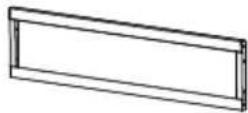
1DQ XTR-FS1305 - 2(x1) (x1) (x1)2DQ XTR-FS1305 - 33DQ XTR-FS1305 - 4
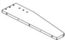
4DQ XTR-FS1305 - 5(x1)5DQ XTR-FS1305 - 6(x2)6DQ XTR-FS1305 - 7(x2)
7DQ XTR-FS1305 - 88DQ XTR-FS1305 - 9(x1)(x1)9DQ XTR-FS1305 - 10(x1)
10 11 12DQ XTR-FS1305 - 11(x1)DQ XTR-FS1305 - 12(x1)DQ XTR-FS1305 - 13(x1)
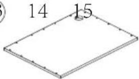
13DQ XTR-FS1305 - 14DQ XTR-FS1305 - 15(x1)DQ XTR-FS1305 - 16(x1)(x1)
16 17 18DQ XTR-FS1305 - 17(x1) (x1) (x1)DQ XTR-FS1305 - 18DQ XTR-FS1305 - 19
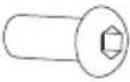
A B CDQ XTR-FS1305 - 20ScrewsM5×8mm (x4)DQ XTR-FS1305 - 21ScrewsM6×8mm (x28)DQ XTR-FS1305 - 22ScrewsM5×10mm (x8)
DDQ XTR-FS1305 - 23ScrewsM4×12mm (x2)EDQ XTR-FS1305 - 24ScrewsM6×12mm (x2)FDQ XTR-FS1305 - 25ScrewsM5×15mm (x10)
GDQ XTR-FS1305 - 26ScrewsM4×35mm (x6)HDQ XTR-FS1305 - 27Allen KeyS=2mm (x1)IDQ XTR-FS1305 - 28Allen KeyS=4mm (x1)
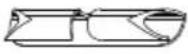
J K LDQ XTR-FS1305 - 29Cable Clip (x4)DQ XTR-FS1305 - 30Cam Lock (x5)DQ XTR-FS1305 - 31Cam Bolt (x5)
MDQ XTR-FS1305 - 32Wood Tip (x19)NDQ XTR-FS1305 - 33Sticker (x1)ODQ XTR-FS1305 - 34(x4)
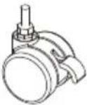
PDQ XTR-FS1305 - 35Cable Hole Cover (x1)QDQ XTR-FS1305 - 36(x2)RDQ XTR-FS1305 - 37Universal Wheel (x4)
SDQ XTR-FS1305 - 38M14 (x1)

OPTIONAL

T
DQ XTR-FS1305 - OPTIONAL - 1

Technical diagram of a structural frame assembly with numbered components and directional arrows indicating movement.

STEP 2

B
I

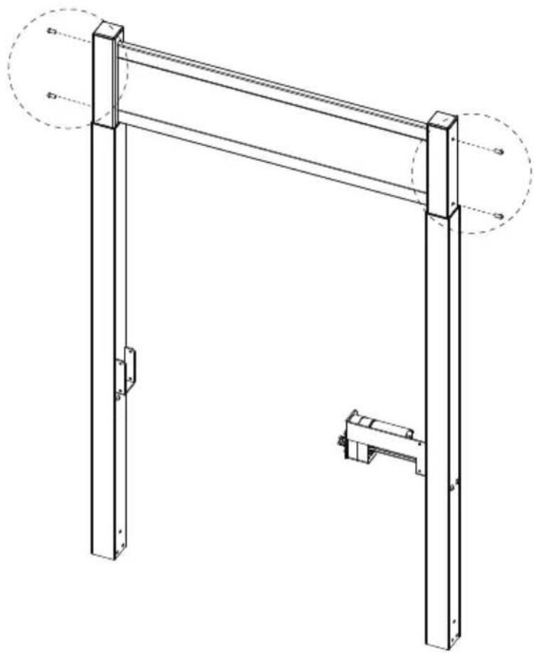
Technical line drawing of a mechanical support structure with two vertical posts and a bracket (no text or symbols)

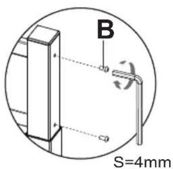
B S=4mm

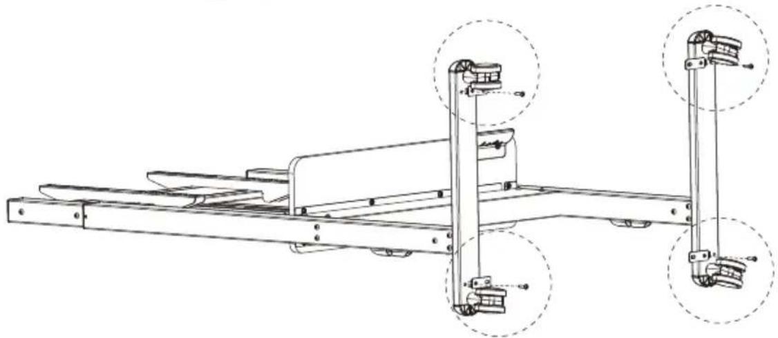
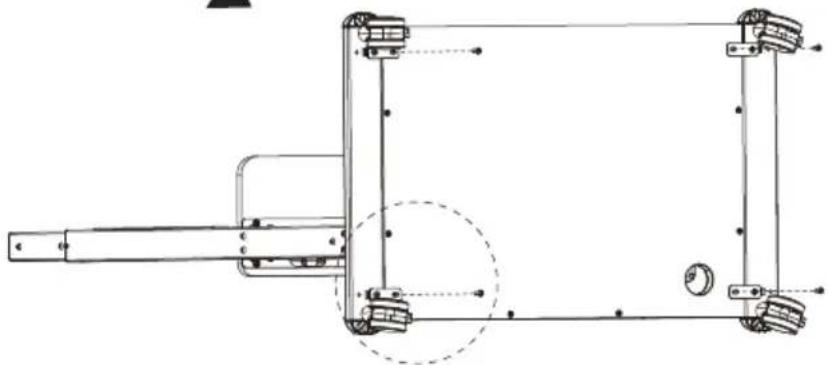
R[YTSH]UniversalWheel (x4)
SM14 (x1)

⑤ S R → ⑤ S R →

STEP 4

BDQ XTR-FS1305 - STEP 4 - 1 M6×8mm(x12)
IS=4mm

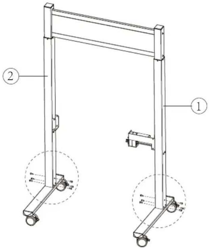
Technical diagram of a mechanical support structure with labeled components 1 and 2

B S=4mm

STEP 5

B
I
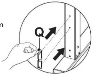
Q

Technical line drawing of a mechanical support frame with two circular components, shown in isometric and dashed views (no text or symbols)

B S=4mm

n Q

STEP 6

Technical diagram of a mechanical lifting frame with numbered components and alignment indicators

H
DQ XTR-FS1305 - STEP 6 - 2
S=2mm

1
Diagram of a mechanical component with directional arrows indicating motion (no text or symbols)

Mechanical assembly diagram showing a bracket with a rotating knob and directional arrow (no text or symbols)

Allen Key S=2mm

Secure the transmission rod to the slot by tightening the pre-assembled set screw using the small allen key.

DQ XTR-FS1305 - STEP 6 - 6

Loosen the knob

Insert the transmission rod into the hex hole and turn the transmission rod clockwise until the left column to the lowest position.

Insert the other end of transmission rod to the slot on the leg (You may rotate the rod slightly for better installation).

Tighten the knob

STEP 7

B
I

Technical line drawing of a mechanical frame structure with wheels and mounting brackets (no text or symbols)

B S=4mm

STEP 8

Technical line drawing of a mechanical frame with wheels and a numbered component (8), no text or symbols present.

Technical line drawing of a metal frame structure with wheels and a cable, no text or symbols present

STEP 9
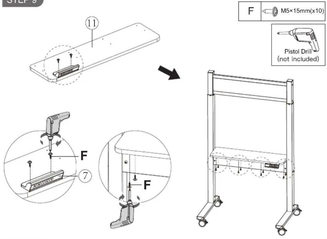
STEP 9 11 F M5×15mm(x10) Pistol Drill (not included) F 7 F

STEP 10

Technical diagram of a mechanical assembly with labeled components and an inset close-up of a train on tracks.

DQ XTR-FS1305 - STEP 8 - 5

Pistol Drill (not included)

Technical line drawing of a rectangular plate with bolt holes and a magnified inset showing a screwdriver inserted into the center (no text or symbols)

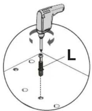
L

STEP 12

Technical line drawing of a mechanical assembly with two plates, a central cavity, and a dashed circle highlighting a component (no text or symbols present)

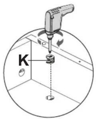
K
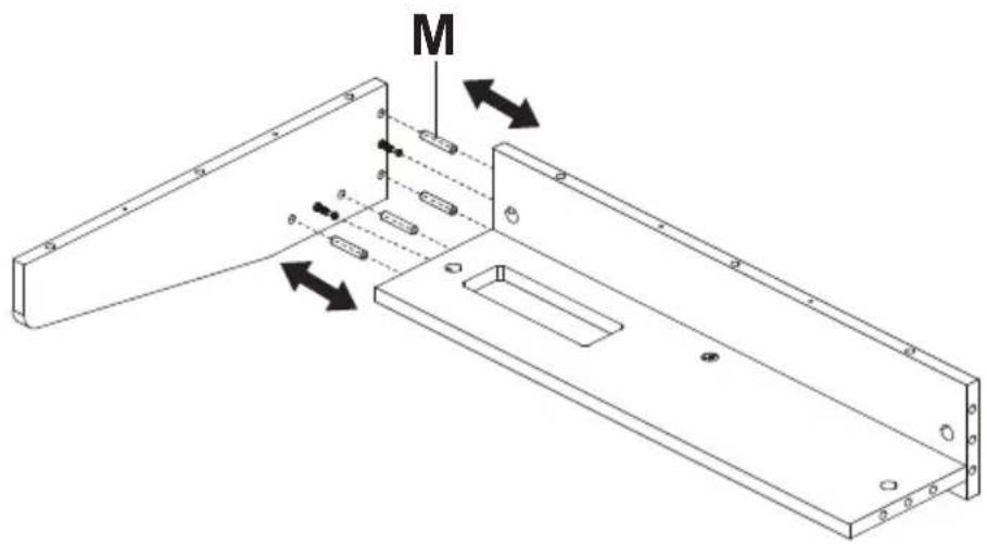
M

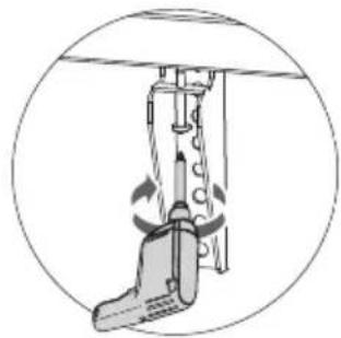
Pistol Drill (not included)

Technical line drawing of a metal bracket with mounting holes and a circular feature, no text or symbols present

M

K

STEP 13

DQ XTR-FS1305 - STEP 13 - 1

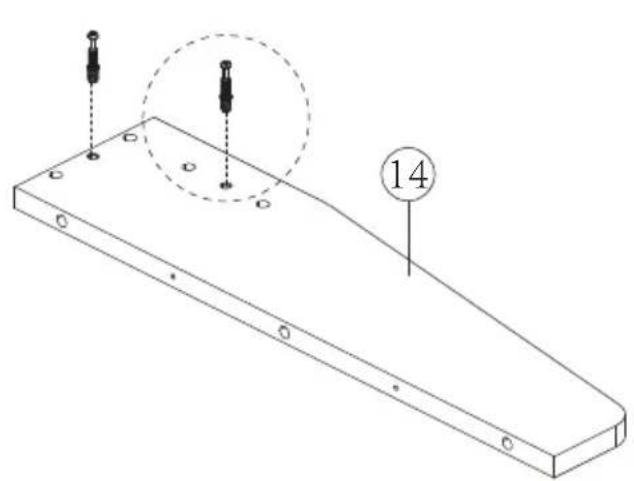
Pistol Drill (not included)

Technical line drawing of a mechanical part with two mounting holes and a circular annotation labeled '14' (no text or symbols beyond the number)

Diagram showing a tool pressing into a circular component labeled 'L', with arrows indicating motion and a dashed line indicating direction.

STEP 14

DQ XTR-FS1305 - STEP 14 - 1

M

DQ XTR-FS1305 - STEP 14 - 3

Pistol Drill (not included)

Technical line drawing of a mechanical bracket with mounting holes and a circular inset detail (no text or symbols)

K

STEP 16

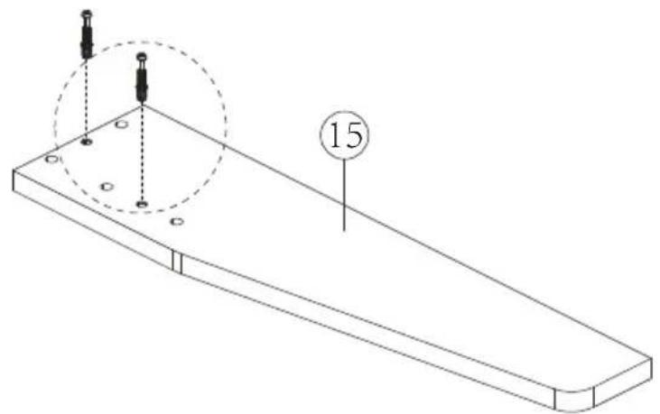
DQ XTR-FS1305 - STEP 16 - 1

Pistol Drill (not included)

Isometric line drawing of a rectangular plate with two small protrusions and a dashed circle highlighting a section, labeled '15' (no text or symbols on the diagram itself)

Diagram of a screwdriver tool in a circular coordinate system with labeled point L (no text or symbols on the diagram itself)

M

M

STEP 18

K

Pistol Drill (not included)

Technical line drawing of a U-shaped metal frame with internal components and mounting holes (no text or symbols)

K

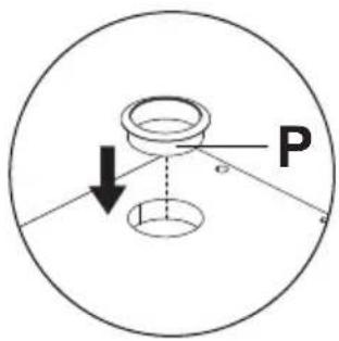
PCable Hole Cover (x1)

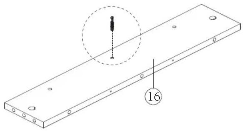
13

P

STEP 20

M

Technical line drawing of a mechanical assembly with no visible text or symbols

Diagram showing a mechanical or structural setup with a downward arrow and labeled point M, likely indicating a force or direction.

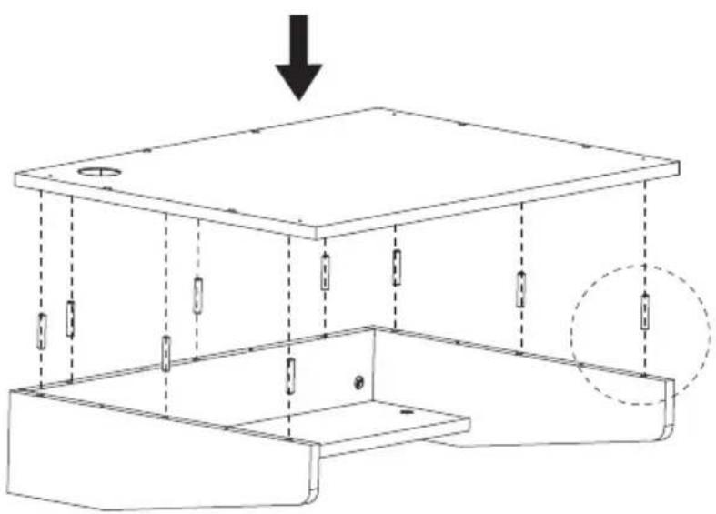
GM4×35mm(x6)

Pistol Drill (not included)

Isometric line drawing of a rectangular plate with a circular hole and multiple vertical supports (no text or symbols)

G

STEP 22
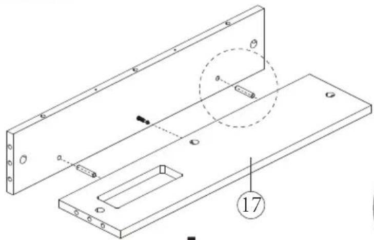
18

D

Diagram showing a pipette dispensing liquid into a device labeled D, with arrows indicating flow direction.

Isometric line drawing of a tray with a small electronic device inside, no text or symbols present

STEP 23

O C

C
O

Pistol Drill (not included)

Technical line drawing of a mechanical assembly with two vertical supports and mounting brackets (no text or symbols)

STEP 24

Technical diagram showing mechanical assembly with downward arrows indicating force or movement on components

C

Pistol Drill (not included)

(not include C

Technical line drawing of a mechanical assembly with no visible text or symbols

A
Technical diagram of a device with labeled components, showing two vertical arms and numbered parts.

T M4x12 (x4) M4x30 (x4) U M5x12 (x4) M5x30 (x4) V M6x12 (x4) M6x30 (x4) W M8x16 (x4) M8x30 (x4) X Φ18X8X20 (x4)Φ18x6.5x1.5(x4)

X T~V OR

W

B
Technical diagram of a device with labeled components, showing two vertical slots and adjustment knobs.

X T~V X OR

OR X W

STEP 26
Line drawing of a mechanical cart with wheels and a side panel, showing a transformation from front view to top view (no text or symbols)

Pistol Drill (not included)

Diagram of a mechanical device inside a circular frame, showing motion arrows and no text or symbols

STEP 27
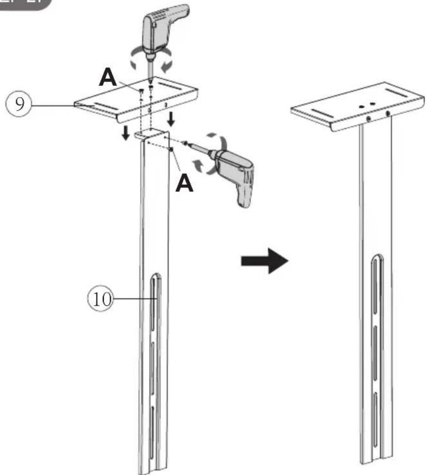
A 9 A 10

ADQ XTR-FS1305 - STEP 24 - 16 M5×8mm(x4)

DQ XTR-FS1305 - STEP 24 - 17

E
I

Technical line drawing of a mechanical support system with wheels and a vertical frame (no text or symbols)

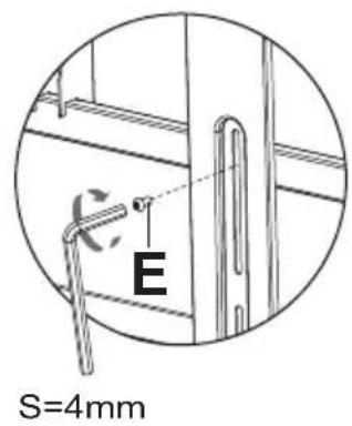
E S=4mm

STEP 29

NSticker (x1)

Technical line drawing of a mechanical device with a control panel and power outlet (no text or symbols)

① N ②

DQ XTR-FS1305 - STEP 29 - 3

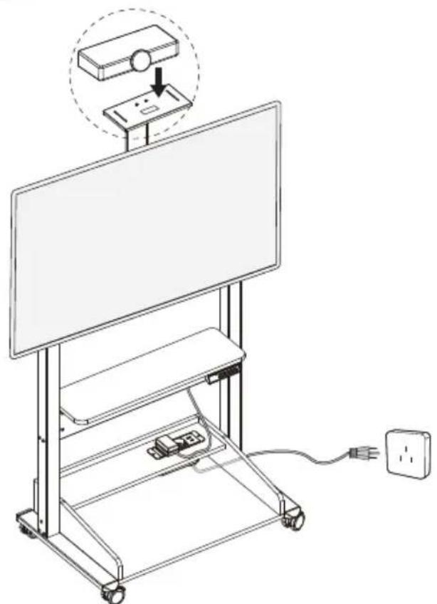
Note: After installing the TV, reset the bracket upwards and pay attention to the interference above to prevent damage to the TV.

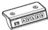
Controller Introduction

120 ^ √ 1 2 3

DQ XTR-FS1305 - Controller Introduction - 2

Press any key once to wake up the display.

Adjust the stand to your preferred height, then long press the 12or □ or □ button until the LED shows H1 or H2 or H3 and flashes for about 3 seconds, then the LED shows the height you have set, then the height memory setting is complete.

DQ XTR-FS1305 - Controller Introduction - 3

Long press the ▲ button to make the support continue to rise. The support stops rising when the button is released, or stops when the maximum height (160cm) is reached.

DQ XTR-FS1305 - Controller Introduction - 4

Long press the ☑ button to keep the bracket falling, stop the bracket falling when the button is released, or stop the bracket when the minimum height (120cm) is reached.

After raising the support to the highest height, press and hold it for 5 seconds, the screen displays "rES" for reset, and when the screen displays the height 160 again, The reset succeeded. Procedure

Protection Mode Error Codes
HotOverheat protection: When the motor operates continuously, it will stop running to prevent damage caused by overheating. Wait for a period of time (15-20minutes) before making any further height adjustments.
E10Sensor malfunction warning: Motor safety sensor cannot be detected. Please power off, unplug the cables of the controller, wait for 5 minutes, then plug in the cables and connect the power again, and perform RES settings again.
E20Overload protection: If the support load exceeds the maximum load, power off, remove some heavy objects from the table, and then plug in the power supply again.
E02Operation status warning: The support stops moving when vibration, shock, or tilt is detected. If the detection result is incorrect, reset it and use it again.
E32Overvoltage warning: The input voltage is too high. If the AC adapter is correct, power off the device, remove the controller cable, wait 5 minutes, plug in the cable, plug in the power, and reset the device.
E31Undervoltage Protection: Input voltage too low. If the correct AC adapter is being used, please power off, unplug the cables of the controller, wait for 5 minutes, then plug in the cables and connect the power again, and perform RES settings again.
-Cable Disconnection Warning: Please power off, unplug the cables of the controller, wait for 5 minutes, then plug in the cables and connect the power again, and perform RES settings again.
Manual assistant
Powered by Anthropic
Waiting for your message
Product information

Brand : DQ

Model : XTR-FS1305

Category : TV Stand