
DeltaStream DS-P7500-16 - Network Equipment TP-LINK - Free user manual and instructions
Find the device manual for free DeltaStream DS-P7500-16 TP-LINK in PDF.


| Product Type | 16-Port Gigabit Managed Switch |
| Model | DeltaStream DS-P7500-16 |
| Brand | TP-Link |
| Ports | 16 x 10/100/1000 Mbps RJ45 |
| Expansion Slots | 2 x Combo SFP Slots |
| Switching Capacity | 36 Gbps |
| MAC Address Table | 8K entries |
| Dimensions (W x D x H) | 440 x 220 x 44 mm (17.3 x 8.7 x 1.7 in) |
| Weight | 3.5 kg (7.7 lbs) |
| Power Supply | 100-240V AC, 50/60 Hz, internal |
| Max Power Consumption | 30W |
| Cooling | Fanless |
| Management | Web GUI, CLI, SNMP v1/v2c/v3, RMON |
| VLAN Support | 802.1Q VLAN, up to 4K VLAN groups |
| QoS | 8 priority queues, port-based, DSCP |
| Security | 802.1X, ACL, Port Security, Storm Control |
| Mounting | Rackmountable (19-inch), Desktop |
| Operating Temperature | 0°C to 45°C (32°F to 113°F) |
| Storage Temperature | -40°C to 70°C (-40°F to 158°F) |
| Humidity | 10% to 90% non-condensing |
| Certifications | CE, FCC, RoHS |
Frequently Asked Questions - DeltaStream DS-P7500-16 TP-LINK
User questions about DeltaStream DS-P7500-16 TP-LINK
0 question about this device. Answer the ones you know or ask your own.
Ask a new question about this device
Download the instructions for your Network Equipment in PDF format for free! Find your manual DeltaStream DS-P7500-16 - TP-LINK and take your electronic device back in hand. On this page are published all the documents necessary for the use of your device. DeltaStream DS-P7500-16 by TP-LINK.
USER MANUAL DeltaStream DS-P7500-16 TP-LINK
DeltaStream Pizzabox Optical Line Terminal
About this Installation Guide
This Installation Guide describes the hardware characteristics, installation methods and the points that should be attended to during the installation. This Installation Guide is structured as follows:
Chapter 1 Introduction
This chapter describes the external components of the device.
Chapter 2 Installation
This chapter illustrates how to install the device.
Chapter 3 Connection
This chapter illustrates how to do the physical connection of the device.
Chapter 4 Configuration
This chapter illustrates how to configure the device.
Appendix A Troubleshooting
Appendix B Hardware Specifications
Appendix C Explanations of The Symbols
Audience
This Installation Guide is for:
Network Engineer
Network Administrator
Conventions
- Some models featured in this guide may be unavailable in your country or region. For local sales information, visit https://www.tp-link.com.
- The figures in this guide are for demonstration purposes only. Your device may differ in appearance from that depicted.
- PoE budget calculations are based on laboratory testing. Actual PoE power budget is not guaranteed and will vary as a result of client limitations and environmental factors.
- This guide uses the specific formats to highlight special messages. The following table lists the notice icons that are used throughout this guide.


Remind to be careful. A caution indicates a potential which may result in device damage.
Remind to take notice. The note contains the helpful information for a better use of the product.
Related Document
The related documents of the product are provided on Download Center. To obtain the latest product information, visit the official website: https://www.tp-link.com.
Chapter 1 Introduction ———— 02
1.1 Product Overview....02
1.2 Appearance....03
Chapter 2 Installation 15
2.1 Package Contents....15
2.2 Safety Precautions....15
2.3 Installation Tools....17
2.4 Product Installation....18
Chapter 3 Connection ———— 21
3.1 Port Connection....21
3.2 Verify Installation....22
3.3 Power On....22
3.4 Initialization....25
Chapter 4 Configuration 26
4.1 Via the MGMT Port....26
4.2 Via the QSFP28/SFP28/QSFP+/SFP+/2.5GE/GE
Port 26
4.3 Via the Console Port....27
Appendix A Troubleshooting 28
Appendix B Specifications 29
Appendix C Explanations of The Symbols — 31
Chapter 1 Introduction
1.1 Product Overview
TP-Link Optical Line Terminal (OLT) products are designed to provide business-class solutions for ISP's access networks, and they are scalable and reliable for deploying services to meet various demands of ISP's customers.
A simplified network topology is shown as the following figure.
![graph TD A["Internet"] --> B["L3 Switch"] B --> C["SIP Server"] B --> D["IPTV Server"] B --> E["PPPoE Server"] B --> F["QSFP28/SFP28/QSFP+/SFP+ port"] B --> G["OLT"] G --> H["PON port"] H --> I["ISP Central Office"] I --> J["Optical Cable"] I --> K["Optical Splitter"] K --> L["XGS-PON&GPON Combo Net…](/content/2026/05/1045770/images/97058469253bd9206042120986f435ffd7c50ba5e73c18b4fe929d4e9646927a.jpg)
1.2 Appearance
■ Front Panel (The figures are for demonstration only. They may differ from your actual products.)
The front panel of DS-P7001-01 is shown as the following figure.

The front panel of DS-P7001-04 is shown as the following figure.

The front panel of DS-P7001-08 is shown as the following figure.

The front panel of DS-P7001-16 is shown as the following figure.
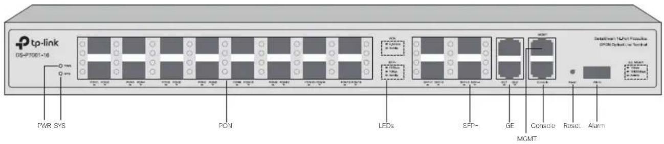
DeltaStream Pizzabox Optical Line Terminal
The front panel of DS-P7500-08 is shown as the following figure.
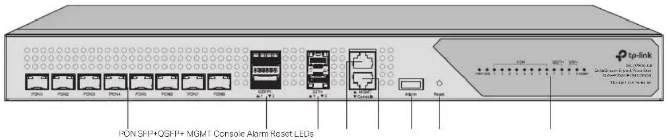
The front panel of DS-P7501-08 is shown as the following figure.

The front panel of DS-P7500-16 is shown as the following figure.
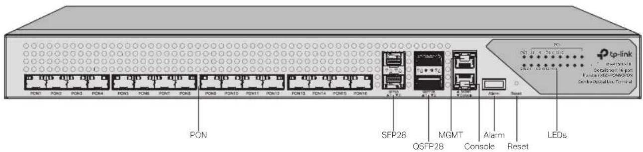
Ports
For DS-P7001-01
| Port Indication | |
| PON | The PON port connects to the GPON network via an OLT SFP module and an optical cable. GPON networks are extended from the PON ports of OLT, and oriented to the locations of ISP's end users. |
| SFP+ | The SFP+ port connects to the uplink network of ISP's central office via an 10 Gbps SFP+ module and an optical cable. |
| 2.5GE (PoE IN) | The 2.5GE (PoE IN) port connects to the uplink network of ISP's central office via an Ethernet cable. |
| MGMT | The MGMT port connects to a management terminal like a PC via an Ethernet cable, and then the network manager can configure and monitor the device via the management webpage. |
| Console | The Console port connects to a management terminal like a PC via an RJ45 console cable, and then the network manager can configure and monitor the device via the CLI (Command Line Interface). |
| Reset | If you want to reset the the device, press and hold the reset button for more than 5 seconds. |
For DS-P7001-04/DS-P7001-08/DS-P7001-16
| Port Indication | |
| PON | The PON port connects to the GPON network via an OLT SFP module and an optical cable. GPON networks are extended from the PON ports of OLT, and oriented to the locations of ISP's end users. |
| SFP+ | The SFP+ port connects to the uplink network of ISP's central office via an 10 Gbps SFP+ module and an optical cable. |
| GE | The GE port connects to the uplink network of ISP's central office via an Ethernet cable. |
| MGMT | The MGMT port connects to a management terminal like a PC via an Ethernet cable, and then the network manager can configure and monitor the device via the management webpage. |
| Console | The Console port connects to a management terminal like a PC via an RJ45 console cable, and then the network manager can configure and monitor the device via the CLI (Command Line Interface). |
| Alarm The Alarm port connects to a monitoring device, sending alarm messages. | |
| Reset | If you want to reset the the device, press and hold the reset button for more than 5 seconds. |
For DS-P7500-08
| Port Indication | |
| PONQSFP+ | The PON port connects to the XGS-PON&GPON network via an OLT SFP module and an optical cable. XGS-PON&GPON networks are extended from the PON ports of OLT, and oriented to the locations of ISP's end users.The QSFP+ port connects to the uplink network of ISP's central office via an 40 Gbps SFP+ module and an optical cable. |
| SFP+ | The SFP+ port connects to the uplink network of ISP's central office via an 10 Gbps SFP+ module and an optical cable. |
| MGMT | The MGMT port connects to a management terminal like a PC via an Ethernet cable, and then the network manager can configure and monitor the device via the management webpage. |
| Console | The Console port connects to a management terminal like a PC via an RJ45 console cable, and then the network manager can configure and monitor the device via the CLI (Command Line Interface). |
| Alarm The Alarm port connects to a monitoring device, sending alarm messages. | |
| Reset | If you want to reset the device, press and hold the reset button for more than 5 seconds. |
For DS-P7501-08/DS-P7500-16
| Port Indication | |
| PON | The PON port connects to the XGS-PON&GPON network via an OLT SFP module and an optical cable. XGS-PON&GPON networks are extended from the PON ports of OLT, and oriented to the locations of ISP's end users. |
| QSFP28 | The QSFP28 port connects to the uplink network of ISP's central office via an 100 Gbps SFP+ module and an optical cable. |
| SFP28 | The SFP28 port connects to the uplink network of ISP's central office via an 25 Gbps SFP+ module and an optical cable. |
| MGMT | The MGMT port connects to a management terminal like a PC via an Ethernet cable, and then the network manager can configure and monitor the device via the management webpage. |
| Console | The Console port connects to a management terminal like a PC via an RJ45 console cable, and then the network manager can configure and monitor the device via the CLI (Command Line Interface). |
| Alarm The Alarm port connects to a monitoring device, sending alarm messages. | |
| Reset | If you want to reset the the device, press and hold the reset button for more than 5 seconds. |
LEDs
For DS-P7001-01
| LED Indication | |
| PWR | On: The device is powered on.Off: The device is powered off or power supply is abnormal.Flashing: Power supply is abnormal. |
| SYS | On: The device works properly.Off: The device works improperly.Flashing Slowly and Then Quickly: The reset button is pressed and held and then the device is reset to the default settings.Flashing Normally: The device is upgrading.Flashing Quickly: There are alarms. |
| PON | Green On: Running at 2.5 Gbps, but no activity.Green Flashing: Running at 2.5 Gbps and transmitting or receiving data.Off: No device is linked to the corresponding port. |
| SFP+ | Green On: Running at 10 Gbps, but no activity.Green Flashing: Running at 10 Gbps and transmitting or receiving data.Yellow On: Running at 1 Gbps, but no activity.Yellow Flashing: Running at 1 Gbps and transmitting or receiving data.Off: No device is linked to the corresponding port. |
| 2.5GE | Green On: Running at 2.5 Gbps, but no activity.Green Flashing: Running at 2.5 Gbps and transmitting or receiving data.Yellow On: Running at 10/100/1000 Mbps, but no activity.Yellow Flashing: Running at 10/100/1000 Mbps and transmitting or receiving data.Off: No device is linked to the corresponding port. |
| MGMT | Green On: Running at 1 Gbps, but no activity.Green Flashing: Running at 1 Gbps and transmitting or receiving data.Yellow On: Running at 10/100 Mbps, but no activity.Yellow Flashing: Running at 10/100 Mbps and transmitting or receiving data.Off: No device is linked to the corresponding port. |
For DS-P7001-04/DS-P7001-08/DS-P7001-16
| LED Indication | |
| PWR | On: The device is powered on.Off: The device is powered off or power supply is abnormal.Flashing: Power supply is abnormal. |
| SYS | On: The device works properly.Off: The device works improperly.Flashing Slowly and Then Quickly: The reset button is pressed and held and then the device is reset to the default settings.Flashing Normally: The device is upgrading.Flashing Quickly: There are alarms. |
| PON | Green On: Running at 2.5 Gbps, but no activity.Green Flashing: Running at 2.5 Gbps and transmitting or receiving data.Off: No device is linked to the corresponding port. |
| SFP+ | Green On: Running at 10 Gbps, but no activity.Green Flashing: Running at 10 Gbps and transmitting or receiving data.Yellow On: Running at 1 Gbps, but no activity.Yellow Flashing: Running at 1 Gbps and transmitting or receiving data.Off: No device is linked to the corresponding port. |
| GE / MGMT | Green On: Running at 1 Gbps, but no activity.Green Flashing: Running at 1 Gbps and transmitting or receiving data.Yellow On: Running at 10/100 Mbps, but no activity.Yellow Flashing: Running at 10/100 Mbps and transmitting or receiving data.Off: No device is linked to the corresponding port. |
For DS-P7500-08
| LED Indication | |
| PWR | On: The device is powered on.Off: The device is powered off or power supply is abnormal.Flashing: Power supply is abnormal. |
| SYS | On: The device works properly.Off: The device works improperly.Flashing Slowly and Then Quickly: The reset button is pressed and held and then the device is reset to the default settings.Flashing Normally: The device is upgrading.Flashing Quickly: There are alarms. |
| PON | Green On: An ONU is linked to the corresponding port.Green Flashing: An ONU is linked to the corresponding port and transmitting or receiving data.Off: No device is linked to the corresponding port. |
| SFP+ | Green On: Running at 10 Gbps, but no activity.Green Flashing: Running at 10 Gbps and transmitting or receiving data.Yellow On: Running at 1 Gbps, but no activity.Yellow Flashing: Running at 1 Gbps and transmitting or receiving data.Off: No device is linked to the corresponding port. |
| QSFP+ | Green On: All 4 individual channels of the QSFP+ are running at 10 Gbps, but no activity.Green Flashing: All 4 individual channels of the QSFP+ are running at 10 Gbps, and transmitting or receiving data.Yellow On: At least 1 individual channel has not running at 10 Gbps, but no activity.Yellow Flashing: At least 1 individual channel has not running at 10 Gbps, and transmitting or receiving data.Off: No device is linked to the corresponding port. |
| MGMT | Green On: Running at 1 Gbps, but no activity.Green Flashing: Running at 1 Gbps and transmitting or receiving data.Yellow On: Running at 10/100 Mbps, but no activity.Yellow Flashing: Running at 10/100 Mbps and transmitting or receiving data.Off: No device is linked to the corresponding port. |
For DS-P7501-08/DS-P7500-16
| LED Indication | |
| PWR | On: The device is powered on.Off: The device is powered off or power supply is abnormal.Flashing: Power supply is abnormal. |
| SYS | On: The device works properly.Off: The device works improperly.Flashing Slowly and Then Quickly: The reset button is pressed and held and then the device is reset to the default settings.Flashing Normally: The device is upgrading.Flashing Quickly: There are alarms. |
| PON | Green On: An ONU is linked to the corresponding port.Green Flashing: An ONU is linked to the corresponding port and transmitting or receiving data.Off: No device is linked to the corresponding port. |
| SFP28 | Green On: Running at 25 Gbps, but no activity.Green Flashing: Running at 25 Gbps and transmitting or receiving data.Yellow On: Running at 10/1 Gbps, but no activity.Yellow Flashing: Running at 10/1 Gbps and transmitting or receiving data.Off: No device is linked to the corresponding port. |
| QSFP28 | Green On: All 4 individual channels of the QSFP28 are running at 25 Gbps, but no activity.Green Flashing: All 4 individual channels of the QSFP28 are running at 25 Gbps, and transmitting or receiving data.Yellow On: At least 1 individual channel has not running at 25 Gbps, but no activity.Yellow Flashing: At least 1 individual channel has not running at 25 Gbps, and transmitting or receiving data.Off: No device is linked to the corresponding port. |
| MGMT | Green On: Running at 1 Gbps, but no activity.Green Flashing: Running at 1 Gbps and transmitting or receiving data.Yellow On: Running at 10/100 Mbps, but no activity.Yellow Flashing: Running at 10/100 Mbps and transmitting or receiving data.Off: No device is linked to the corresponding port. |
- Rear Panel
The figure is for demonstration purposes only. Your device may differ in appearance from the depicted. Here, the AC Power Supply Module as the main power supply and the DC Power Supply Module as the backup power supply as an example.
The rear panel of DS-P7001-01 is shown as the following figure.

DC Power InputKensington Security Slot Grounding Te
The rear panel of DS-P7001-04 is shown as the following figure.

The rear panel of DS-P7001-08 is shown as the following figure.

Grounding Terminal Kensington Security Slot Backup Power Supply Panel Main Power Supply Panel
DeltaStream Pizzabox Optical Line Terminal
The rear panel of DS-P7001-16 is shown as the following figure.

The rear panel of DS-P7500-08/DS-P7501-08 is shown as the following figure.
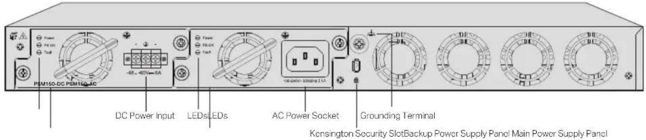
The rear panel of DS-P7500-16 is shown as the following figure.


Caution:
For products that utilize pluggable power modules, it is not permissible to leave the power slots empty during operation. A power module (which can remain inactive) or a baffle must be inserted to prevent disruption of the overall heat dissipation airflow and compromise of the cooling function.
Grounding Terminal
The device already comes with lightning protection mechanism. You can also ground the device through the PE (Protecting Earth) cable of AC cord or with Ground Cable. For detailed lightning protection measures, refer to the Lightning Protection Guide from the website: https://www.tp-link.com/us/configuration-guides/lightning_protection_guide/.
Kensington Security Slot
Secure the lock (not provided) into the security slot to prevent the device from being stolen.
AC Power Socket
Plug the negative connector of the power cord directly into the AC power socket and plug the positive connector into an AC power outlet. Make sure that the voltage of the power supply meets the
requirement of the input (100-240V\~ 50/60Hz).
DC Adapter Input (For DS-P7001-01)
Use the DC Adapter provided in the package to power on the OLT.
DC Power Input
Attach the power wires to the DC power input. We recommend you use 18-14 AWG wires. Connect the positive pole of the DC power supply to the "+" end, and the negative pole to the "-" end. Make sure the power supply meets the requirement of the input (48-60V). An all-pole mains switch in accordance with EN 62368-1 2014 Annex L shall be incorporated in the electrical installation of the building. And the disconnect device shall have a contact separation at least 2.0mm.
Current Sharing Mode Power Supply Panel (Only for DS-P7500-16)
Both power slots have the same priority, and when both power modules are powered on, each power source provides half of the total power output, achieving current sharing between the two power sources. In the event that one of the power sources is unplugged or suffers a power failure, the other power source will provide full power output, ensuring the product continues to operate normally.
Main Power Supply Panel / Backup Power Supply Panel (Only for Certain Devices)
There are multiple power supply panels on certain devices, where power supply modules can be installed. The main power supply panel takes priority over the backup one. If the main one works normally, the backup one does not work. If the main one fails, the backup one starts to work.
AC Power Supply Module / DC Power Supply Module (Only for Certain Devices)
There are detachable power supply modules on certain devices. If you want to detach the power supply module, you can hot swap it by unscrewing the module and pulling the handle. If needed, you can purchase additional power supply modules.

Note:
For detailed information about power supply modules, refer to the Installation Guide of Power Supply Modules, which can be found on the Support page of the product at our website.

Note:
The product label can be found at the bottom of the product and its I.T.E power supply.


Caution
Shock hazard
Disconnect all power sources
LEDs (Only for PSM150-AC or PSM150-DC)
| LED Indication | |
| Power | On: The power supply module is powered on.Off: The power supply module is powered off or power supply is abnormal. |
| PS OK | On: The power supply module is supplying power normally.Off: The power supply module is not supplying power or power supply is abnormal. |
| Fault | On: There are some faults and the power supply module is working abnormally.Off: There are no faults and the power supply module is working normally. |
LEDs (Only for CRPS)
| LED Indication | |
| GREEN ON Output is normal. | |
| AMBER ON | AC power cord is unplugged or there is no AC power, while another parallel power module has AC power input.Or there is a critical event (such as failure, over-current protection, short circuit, over-voltage protection, fan failure, over-temperature protection, input over-voltage protection) causing the shutdown of the power module. |
| 1Hz Blinking GREEN | 1) Power module standby with AC present.2) Only 12Vstby output is available.3) Power module standby state as defined in the Cold Redundancy section of the CRPS specification. |
| 2Hz Blinking GREEN | Software upgrade is in progress. |
| 1Hz Blinking AMBER | There is a warning event with the power module continuing to operate (high temperature, high power, high current, fan speed reduction). |
| OFF There is no AC input to all power modules. | |
Chapter 2 Installation
2.1 Package Contents
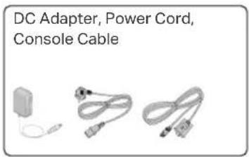
Make sure that the package contains the following items. Please contact your distributor, if any of the listed items is damaged or missing. The figures are for demonstration only. The actual items may differ in appearance and quantity from the depicted.



2.2 Safety Precautions
To avoid any device damage and bodily injury caused by improper use, you should observe the following rules.
■ Safety Precautions
- Keep the power off during the installation.
- Wear an ESD-preventive wrist strap, and make sure that the wrist strap has a good skin contact and is well grounded.
- Use only the power cord provided with the device.
- Make sure that the supply voltage matches the specifications indicated on the rear panel of the device.
- Ensure that the device is installed in a well-ventilated environment and its ventilation hole is not blocked.
- Do not open or remove the cover of the device.
- Before cleaning the device, cut off the power supply. Do not clean it by the waterish cloth, and never use any other liquid cleaning method.
- Place the device with its bottom surface downward.
■ Site Requirements
Temperature/Humidity

Keep the equipment room at an appropriate level of temperature and humidity. Too much or too little humidity may lead to bad insulation, leakage of electricity, mechanical property changes, and corrosion. High temperatures may accelerate aging of the insulation materials, significantly shortening the service life of the device. To find out the best temperature and humidity conditions for the device, check the Appendix B Specifications.
Clearness

The dust accumulated on the device can be absorbed by static electricity and result in poor contact of metal contact points. Some measures have been taken for the device to prevent static electricity, but too strong static electricity can cause deadly damage to the electronic elements on the internal circuit board. To avoid the effect of static electricity on the operation of the device, attach much importance to the following items:
- Dust the device regularly, and keep the indoor air clean.
- Keep the device well grounded and ensure that the static electricity has been transferred.
Electromagnetic Interference
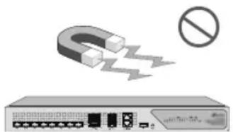
Electronic elements including capacitance and inductance on the device can be affected by external interferences, such as conducted emission by capacitance coupling, inductance coupling, and impedance coupling. To decrease the interferences, make sure to take the following measures:
- Use the power supply that can effectively filter interference from the power grid.
- Keep the device far from high-frequency and strong-current devices such as radio transmitting station.
- Use electromagnetic shielding when necessary.
Lightning Protection

Extremely high voltage currents can be produced instantly when lightning occurs and the air in the electric discharge path can be instantly heated up to 20,000 °C. As this instant current is strong enough to damage electronic devices, more effective lightning protection measures should be taken.
- Ensure that the rack and the device are well earthed.
- Make sure the power socket has a good contact with the ground.
- Keep a reasonable cabling system and avoid induced lightning.
- Use the signal SPD (Surge Protective Device) when wiring outdoor.

Note:
For detailed lightning protection measures, refer to the Lightning Protection Guide from the website:
https://www.tp-link.com/us/configuration-guides/lightning_protection_guide/.
Installation Site

When installing the device on a rack or a flat workbench, attach much importance to the following items:
- The rack or workbench is flat, stable, and sturdy enough to support the weight of 5.5 kg at least.
- The rack or workbench has a good ventilation system. The equipment room is well ventilated.
- The rack is well grounded. Keep the device less than 1.5 meters away from the power socket.
2.3 Installation Tools
- Phillips screwdriver
- ESD-preventive wrist wrap
- Cables

Note:
These tools are not included with our product. If needed, you can purchase them separately.
2.4 Product Installation
- Rack Installation
The package includes 4 pairs of different rack-mounting brackets, their pictures are depicted below and may differ from the actual products.

Before installing the device in an EIA standard-sized, 19-inch rack, please check the efficiency of the grounding system and the stability of the rack, then wear an ESD-preventive wrist strap, and make sure that it has good skin contact and is well grounded. Bracket B & C have two adjustable ears, please measure the distance between the front-post rack and the rear-post rack, and determine a suitable mounting method from below:
| Method Demonstration | Rack Distance(For devicewith a depth of380mm) | Rack Distance(For devicewith a depth of420mm) | Rack Distance(For devicewith a depth of460mm) | |
| Front:Bracket DRear:Bracket A (Screw HoleGroup 1) + Bracket B (Eartowards back) |  | 498-640mm 538-680mm 578-720mm | ||
| Front:Bracket DRear:Bracket A (Screw HoleGroup 1) + Bracket C (Eartowards back) | 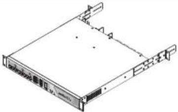 | 477-498mm 517-538mm 557-578mm | ||
| Front:Bracket DRear:Bracket A (Screw HoleGroup 2) + Bracket C (Eartowards back) | 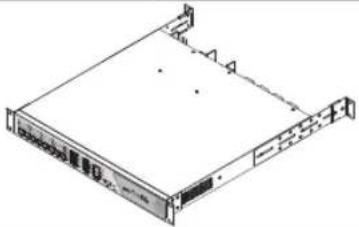 | 429-477mm 469-517mm 509-557mm | ||
| Front:Bracket DRear:Bracket A (Screw HoleGroup 2) + Bracket C (Eartowards front) | 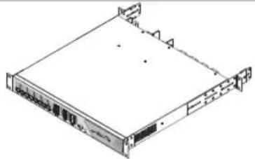 | 410-429mm 450-469mm 490-509mm | ||
| Front:Bracket DRear:Bracket A (Screw HoleGroup 3) + Bracket C (Eartowards back) |  | 357-410mm 397-450mm 437-490mm | ||
| Front:Bracket DRear:Bracket A (Screw HoleGroup 2) + Bracket B (Eartowards back) |  | 282-410mm 322-450mm 362-490mm | ||
To install the device in an EIA standard-sized, 19-inch rack, follow the instructions described below:
- Check the efficiency of the grounding system and the stability of the rack.
- Attach the mounting brackets (B or C) to the rear-post racks and secure them with the provided M6 screws, as illustrated in the following figure.
Figure 2-1 Installing Brackets on Racks

- Secure the supplied rack-mounting brackets to each side of the device with supplied screws, as illustrated in the following figure.

- After the brackets are attached to the device, use suitable screws (not provided) to secure the brackets to the rack, as illustrated in the following figure.
Figure 2-2 Installing Switch on Racks


Caution:
- Leave 5 to 10cm gaps around the devices for air circulation.
- Avoid placing heavy things on the device.
- Place the device with its bottom facing downwards.
- Mount devices in sequence from the bottom to top of the rack and ensure a certain clearance between devices for the purpose of heat dissipation.
Chapter 3 Connection
3.1 Port Connection
Connect the ports of OLT to the devices and networks according to your needs. Some options for port connection are demonstrated in the following figure.
![graph TD A["Internet"] --> B["ISP Central Network"] B --> C["OLT"] C --> D["PON port Console port"] D --> E["Optical Cable"] D --> F["Optical Splitter"] D --> G["XGS-PON&GPON Combo Network"] D --> H["GPON Networkor"] C --> I["Management PC (Web UI)"] C --> J["Management PC (CLI)"] C --> K["OP"] styl…](/content/2026/05/1045770/images/2b1309df17a888043d1994c16899afadaa42d8b4df96643afb585bcfee6fd971.jpg)
1 Install the OLT SFP module to the PON port and connect it to the XGS-PON&GPON Network or GPON network using an optical cable.
2 Install the 100 Gbps QSFP28 module / 25 Gbps SFP28 module / 40 Gbps QSFP+ module / 10 Gbps SFP+ module into the QSFP28/SFP28/QSFP+/SFP+ port, and connect it to the ISP central network using an optical cable.
3 Connect the MGMT port to the management PC using an Ethernet cable in order to configure and monitor the device via the web UI.
4 Connect the Console port to the management PC using an RJ45 console cable in order to configure and monitor the device via the CLI.
3.2 Verify Installation
After completing the installation, verify the following items:
- There should be 5 to 10 cm of clearance around the device for ventilation and make sure the air flow is adequate.
- The voltage of the power supply meets the requirement of the input voltage of the device.
- The power socket, device and rack are well grounded.
- The device is correctly connected to other network devices.
3.3 Power On

Note:
- You can use either AC or DC power supply to power the device. However, it is recommended to use both AC and DC power supply simultaneously as backup for each other in case of power failure.
- For DS-P7001-01, It's recommended that you use a passive PoE adapter or a PoE switch for power supply.
- For DS-P7001-04, the AC power supply takes priority over the DC power supply. If the AC power supply works normally, the DC power supply does not work. If the AC power supply fails, the DC power supply starts to work.
- For DS-P7001-08/DS-P7001-16/DS-P7500-08/DS-P7501-08/DS-P7500-16, there are three modes of dual power supplies, i.e. AC-DC, AC-AC, and DC-DC. If you use AC-DC, it's recommended that you install the DC power supply module on the backup panel and the AC power supply module on the main panel. It's recommended that you use a standard AC power outlet for main power supply, and a UPS (Uninterruptible Power Supply) for backup power supply in case of power failure.
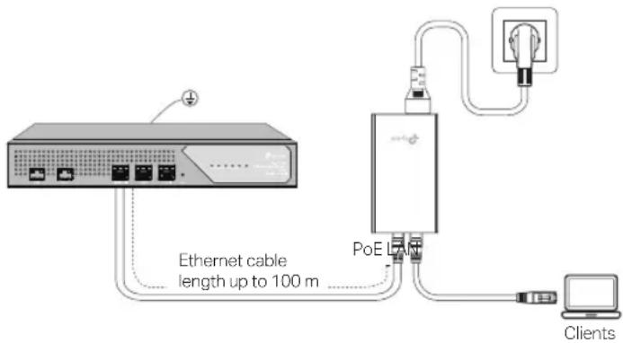
■ Using Passive PoE Adapter (Only for DS-P7001-01)
In the following figures, we take DS-P7001-01 as an example. Your device may differ in appearance from the depicted.
The device can be powered via the provided passive PoE adapter which complies with LPS or PS2 standard. Connect the device to a Power over Ethernet (PoE) adapter as follows:
■ Using PoE Switch (Only for DS-P7001-01)
In the following figures, we take DS-P7001-01 as an example. Your device may differ in appearance from the depicted.
The device can be powered via a PSE device (such as a PoE switch) which complies with LPS or PS2 standard. Connect an Ethernet cable from the PoE switch to the Ethernet port. The PoE switch should comply with 802.3at.
![graph TD A["Power Source"] --> B["Pod 80000000"] B --> C["Client"] C --> D["Server"] D --> E["Switch"] style A fill:#f9f,stroke:#333 style E fill:#ccf,stroke:#333](/content/2026/05/1045770/images/8a97cadce197c057c5ae58decd02d7f47a1f5ab76c9cff2ec654aa8ed16674d2.jpg)

Note:
The device can be powered via a PSE device (such as a PoE switch) which complies with Power Source Class 2 (PS2) or Limited Power Source (LPS) and Electrical Energy Source Class 1(ES1) of IEC 62368-1.
■ Using AC Power Supply
Plug the female connector of the provided power cord into the power socket of the device, and the male connector into a power outlet with earthing connection. Make sure that the voltage of the power supply meets the requirement of the input (100-240V\~ 50/60Hz). In the following figure, we take DS-P7500-08 as an example. Your device may differ in appearance from the depicted.


Caution:
For AC power supply, please use the provided AC power cord.
■ Using DC Power Supply
In the following figures, we take DS-P7500-08 as an example. Your device may differ in appearance from the depicted.
1. Connect the power cord
It is recommended to use an 18-14 AWG power cord to connect the power supply equipment and the DC power input of the device, and make sure that the connection is reliable. When connecting, make sure that the positive and negative poles of the power supply equipment correspond to the positive and negative poles of the device, and that the power supply meets the requirement of the input. An all-pole mains switch in accordance with EN 62368-1 2014 Annex L shall be incorporated in the electrical installation of the building. And the disconnect device shall have a contact separation at least 1.5mm (For DS-P7500-08/DS-P7501-08/DS-P7500-16) or 2.0mm (For DS-P7001-04/DS-P7001-08/DS-P7001-16).

Note:
For DS-P7001-01, you should use the DC Adapter provided in the package to power on the OLT.
DeltaStream Pizzabox Optical Line Terminal
2. Connect to the ground
In different environments, the device may be grounded differently. The following will instruct you to connect the device to the ground in two ways. Note that the protective earthing terminal must be connected to the installation protective earthing conductor.
- Use the grounding bar
If the device is installed in the Equipment Room, where a grounding bar is available, it is recommended to connect the device to the grounding bar with an 18-14 AWG ground cable as shown in the following figure.
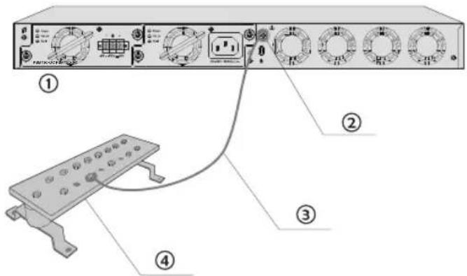
① Device (Rear Panel)
② Grounding Terminal
③ Ground Cable (18-14 AWG)
④ Grounding Bar
- Equipotential bonding
Equipotential bonding is the practice of intentionally electrically connecting all earthed systems to the same grounding grid or connecting the grounding grids of all the earthed systems together through the ground or overground metal so as to create an earthed equipotential zone. When lightning occurs, the high voltage produced by lightning current in all systems will meanwhile exist in their ground cables, and thus all ground cables have the same electrical potential and basically eliminate the electric strikes between the systems. The figure below illustrates how to practice equipotential bonding in a network.

Note:
Equipment grounding instructions (for Denmark, Finland, Norway, Sweden)
① Grounding Terminal Equipotential Bonding Cable
③
④ Grounding Bar Ground Cable (1)

Caution:
- The product can be powered by a DC power source such as accumulator cell and a power supply server. The DC power supply should comply with EN 62368-1 2014 clause 5.4.2.3.2.3, and the transient voltage shall be no more than 2500Vpeak .
- For DC power supply, please note that the power wires and disconnecting device are not included with our product. If needed, you can purchase them separately.
- For DC power supply, the rating of the external overcurrent protective device shall not exceed 16 A (2.5A for DS-P7001-01).
3.4 Initialization
After the device is powered on, it begins the Power-On Self-Test. A series of tests run automatically to ensure the device functions properly. During this time, its LED indicators will respond as follows:
- The PWR LED keeps on all the time.
- The SYS LED flashes momentarily and turns off. After the initial process succeeds, the SYS LED keeps on.
- The port LEDs flash momentarily and turn off. Then the port LEDs start to indicate status of ports normally.
Chapter 4 Configuration
The device supports three configuration options:
- Via the MGMT Port
• Via the QSFP28/SFP28/QSFP+/SFP+/2.5GE/GE Port - Via the Console Port

Note:
For the detailed configurations, refer to the User Guide of the device.
4.1 Via the MGMT Port
- Connect the MGMT port of OLT to the management PC using an Ethernet cable.

- Set the IP address of the PC as 192.168.1.x/24 (x is a number between 2 and 254).
- You can access the device using the Web UI or the CLI.
- Using the Web UI: Open the web browser on the PC. Enter 192.168.1.1 in the address bar to open the web UI of the device. Log in to the web UI. The default username and password are both admin. The first time you log in, you are required to change the password for security purposes.
- Using the CLI: Use a telent or SSH terminal to access 192.168.1.1 to open the CLI of the device. Log in to the CLI. The default username and password are both admin. The first time you log in, you are required to change the password for security purposes.
4.2 Via the QSFP28/SFP28/QSFP+/SFP+/2.5GE/GE Port
- Make sure your PC has network access to the QSFP28/SFP28/QSFP+/SFP+/2.5GE/GE port of OLT.
![graph TD PC["PC"] --> Network["Network"] Network --> OLT["OLT"] OLT --> QSFP28/SFP28/QSFP+/SFP+/2.5GE/GE_Port["QSFP28/SFP28/QSFP+/SFP+/2.5GE/GE Port"]](/content/2026/05/1045770/images/cc1038bafd030c6a2448a2283cdf7ffa9632632d89ae703ea14a3d6664006a57.jpg)
- Set the IP address of the PC as 192.168.0.x/24 (x is a number between 2 and 254).
- You can access the device using the Web UI or the CLI.
- Using the Web UI: Open the web browser on the PC. Enter 192.168.0.1 in the address bar to open the web UI of the device. Log in to the web UI. The default username and password are both admin. The first time you log in, you are required to change the password for security purposes.
- Using the CLI: Use a telent or SSH terminal to access 192.168.0.1 to open the CLI of the device. Log in to the CLI. The default username and password are both admin. The first time you log in, you are required to change the password for security purposes.
4.3 Via the Console Port
- Connect the Console port of OLT to the management PC using an RJ45 console cable.

- Start the terminal emulation program (such as the Hyper Terminal) on the PC and configure the terminal emulation program as follows:
| Baud Rate | Data Bits | Parity | Stop Bits | Flow Control |
| 38400 bps 8 None | 1 None |
Appendix A Troubleshooting
Q1. What could I do if I forgot the username and password of the device?
You can reset the device by holding the reset button for more than 5 seconds. Note that all the configurations will be lost after resetting the device.
Q2. Why does the PWR/Power LED work abnormally?
The PWR/Power LED should be lit up when the power system works normally. If the PWR/Power LED worked abnormally, take the following steps:
- Make sure that the power cable is connected properly, and the power contact is normal.
- Make sure the voltage of the power supply meets the requirement of the input voltage of the device.
Q3. What should I do if I cannot access the web management page?
Try the following:
- Check every port LED on the device and make sure the Ethernet cable is connected properly.
- Try another port on the device and make sure the Ethernet cable is suitable and works normally.
- Power off the device and, after a while, power it on again.
- Make sure the IP address of your PC is set within the subnet of the device.
- If you still cannot access the configuration page, reset the device to its factory defaults. Note that all the configurations will be lost after resetting the device.
Appendix B Specifications
| Item Content | ||
| Standards | IEEE 802.3, IEEE 802.3i, IEEE 802.3u, IEEE 802.3ab, IEEE 802.3ad, IEEE 802.3ae, IEEE 802.3z, IEEE 802.3x, IEEE 802.1p, IEEE 802.1q, IEEE 802.1d, IEEE 802.1s, IEEE 802.1w, IEEE 802.1ah, ITU G.984, ITU G.988,ITU 9807 (For DS-P7500-08/DS-P7501-08/DS-P7500-16) | |
| Transmission Medium(For DS-P7001-01) | 10BASE-T: UTP category 3 or above cable (maximum 100 m), EIA/TIA-568 100Ω STP (maximum 100 m)100BASE-TX: UTP category 5 or above cable (maximum 100 m), EIA/TIA-568 100Ω STP (maximum 100 m)1000BASE-T: UTP category 5e or above cable (maximum 100 m), EIA/TIA-568 100Ω STP (maximum 100 m)2500BASE-T: UTP category 5e or above cable (maximum 100 m), EIA/TIA-568 100Ω STP (maximum 100 m)1000BASE-SX/LX/LX10/BX10: MMF, SMF10GBASE-SR/LR: MMF, SMF10GSFP+CU SFP+ Direct Attach Cable (TXC432-CU1M, TXC432-CU3M)GPON SFP | |
| Transmission Medium(For DS-P7001-04/DS-P7001-08/DS-P7001-16) | 10BASE-T: UTP category 3 or above cable (maximum 100 m), EIA/TIA-568 100Ω STP (maximum 100 m)100BASE-TX: UTP category 5 or above cable (maximum 100 m), EIA/TIA-568 100Ω STP (maximum 100 m)1000BASE-T:UTP category 5e or above cable (maximum 100 m), EIA/TIA-568 100Ω STP (maximum 100 m)1000BASE-SX/LX/LX10/BX10: MMF, SMF10GBASE-SR/LR: MMF, SMF10GSFP+CU SFP+ Direct Attach Cable (TXC432-CU1M, TX C432-CU3M)GPON SFP | |
| Transmission Medium(For DS-P7500-08) | 10BASE-T: UTP category 3 or above cable (maximum 100 m), EIA/TIA-568 100Ω STP (maximum 100 m)100BASE-TX: UTP category 5 or above cable (maximum 100 m), EIA/TIA-568 100Ω STP (maximum 100 m)1000BASE-T:UTP category 5e or above cable (maximum 100 m), EIA/TIA-568 100Ω STP (maximum 100 m)1000BASE-SX/LX/LX10/BX10: MMF, SMF10GBASE-SR/LR: MMF, SMF 40GBASE-SR4/LR4: MMF, SMF10GSFP+CU SFP+ Direct Attach Cable (TXC432-CU1M, TXC432-CU3M)40GBASE-CR4 QSFP+ Direct Attach Cable40GBASE-CR4 QSFP+ to 4 10GBASE-CR4 SFP+ Direct Attach Breakout CableGPON SFP XGS-PON SFP+ XGS-PON & GPON Combo SFP+ | |
| Transmission Medium(For DS-P7501-08/DS-P7500-16) | 10BASE-T: UTP category 3 or above cable (maximum 100 m), EIA/TIA-568 100Ω STP(maximum 100 m) | |
| 100BASE-TX: UTP category 5 or above cable (maximum 100 m), EIA/TIA-568 100Ω STP(maximum 100 m) | ||
| 1000BASE-T: UTP category 5e or above cable (maximum 100 m), EIA/TIA-568 100Ω STP(maximum 100 m) | ||
| 1000BASE-SX/LX/LX10/BX10: MMF, SMF | ||
| 10GBASE-SR/LR: MMF, SMF | 40GBASE-SR4/LR4: MMF, SMF | |
| 25GBASE-SR/LR: MMF, SMF | 100GBASE-SR4/LR4: MMF, SMF | |
| 25GSFP+CU SFP28 Direct Attach Cable (TXC432-CU1M, TXC432-CU3M) | ||
| 100GBASE-CR4 QSFP28 Direct Attach Cable | ||
| 100GBASE-CR4 QSFP28 to 4 25GBASE-CR4 SFP+ Direct Attach Breakout Cable | ||
| GPON SFP XGS-PON SFP+ XGS-PON & GPON Combo SFP+ | ||
| Operating Temperature 0 °C to 50 °C (32 °F to 122 °F) | ||
| Storage Temperature -40 °C to 70 °C (-40 °F to 158 °F) | ||
| Operating Humidity 10% to 90% RH Non-condensing | ||
| Storage Humidity 5% to 90% RH Non-condensing | ||
| Altitude Sea level to 4,000 m | ||
Appendix C Explanations of The Symbols
| [ST67] | Class II equipment | |
 | AC voltage | |
 | DC voltage | |
 | For indoor use only | |
 | Energy efficiency Marking (level VI) | |
 | RECYCLINGThis product bears the selective sorting symbol for Waste electrical and electronic equipment (WEEE). This means that this product must be handled pursuant to European directive 2012/19/EU in order to be recycled or dismantled to minimize its impact on the environment.User has the choice to give his product to a competent recycling organization or to the retailer when he buys a new electrical or electronic equipment. | |
 | Caution | |
 | Operator's manual | |
 | Caution, risk of electric shock | |
 | Disconnection, all power plugs | |
 | Functional earthing |
EU Declaration of Conformity
TP-Link hereby declares that the device is in compliance with the essential requirements and other relevant provisions of directives 2014/30/EU, 2014/35/EU, 2011/65/EU and (EU)2015/863.
The original EU declaration of conformity may be found at https://www.tp-link.com/en/support/ce/
UK Declaration of Conformity
TP-Link hereby declares that the device is in compliance with the essential requirements and other relevant provisions of the Electromagnetic Compatibility Regulations 2016 and Electrical Equipment (Safety) Regulations 2016.
The original UK declaration of conformity may be found at https://www.tp-link.com/support/ukca/


- Keep the device away from water, fire, humidity or hot environments.
- Do not attempt to disassemble, repair, or modify the device. If you need service, please contact us.
- The plug on the power supply cord is used as the disconnect device, the socket-outlet shall be easily accessible. (Devices that require power cord)
- Do not use damaged charger or USB cable to charge the device. (Devices that require power adapter)
- Do not use any other chargers than those recommended. (Devices that require power adapter)
• Adapter shall be installed near the equipment and shall be easily accessible. (Devices that require power adapter) - Place the device with its bottom surface downward.
- Plug the product into the wall outlets with earthing connection through the power supply cord. (Devices that require power cord)
- The Equipment marking is at the bottom of the device.
Please read and follow the above safety information when operating the device. We cannot guarantee that no accidents or damage will occur due to improper use of device. Please use this product with care and operate at your own risk.

For technical support, user guides, and other information, please visit https://www.tp-link.com/en/support/download/, or scan the QR code.


- ABOUT THIS INSTALLATION GUIDE
- CHAPTER 1 INTRODUCTION
- CHAPTER 2 INSTALLATION
- CHAPTER 3 CONNECTION
- CHAPTER 4 CONFIGURATION
- APPENDIX A TROUBLESHOOTING
- AUDIENCE
- CONVENTIONS
- RELATED DOCUMENT
- CHAPTER 1 INTRODUCTION ———— 02
- CHAPTER 2 INSTALLATION 15
- CHAPTER 3 CONNECTION ———— 21
- CHAPTER 4 CONFIGURATION 26
- APPENDIX A TROUBLESHOOTING 28
- APPENDIX B SPECIFICATIONS 29
- APPENDIX C EXPLANATIONS OF THE SYMBOLS — 31
- 1.1 PRODUCT OVERVIEW
- 1.2 APPEARANCE
- PORTS
- LEDS
- REAR PANEL
- CAUTION
- GROUNDING TERMINAL
- KENSINGTON SECURITY SLOT
- AC POWER SOCKET
- DC ADAPTER INPUT (FOR DS-P7001-01)
- DC POWER INPUT
- CURRENT SHARING MODE POWER SUPPLY PANEL (ONLY FOR DS-P7500-16)
- MAIN POWER SUPPLY PANEL / BACKUP POWER SUPPLY PANEL (ONLY FOR CERTAIN DEVICES)
- AC POWER SUPPLY MODULE / DC POWER SUPPLY MODULE (ONLY FOR CERTAIN DEVICES)
- NOTE
- 2.1 PACKAGE CONTENTS
- 2.2 SAFETY PRECAUTIONS
- SAFETY PRECAUTIONS
- SITE REQUIREMENTS
- CLEARNESS
- ELECTROMAGNETIC INTERFERENCE
- LIGHTNING PROTECTION
- INSTALLATION SITE
- 2.3 INSTALLATION TOOLS
- 2.4 PRODUCT INSTALLATION
- RACK INSTALLATION
- 3.1 PORT CONNECTION
- 3.2 VERIFY INSTALLATION
- 3.3 POWER ON
- USING PASSIVE POE ADAPTER (ONLY FOR DS-P7001-01)
- USING POE SWITCH (ONLY FOR DS-P7001-01)
- USING AC POWER SUPPLY
- USING DC POWER SUPPLY
- CONNECT THE POWER CORD
- CONNECT TO THE GROUND
- 3.4 INITIALIZATION
- 4.1 VIA THE MGMT PORT
- 4.2 VIA THE QSFP28/SFP28/QSFP+/SFP+/2.5GE/GE PORT
- 4.3 VIA THE CONSOLE PORT
- Q1. WHAT COULD I DO IF I FORGOT THE USERNAME AND PASSWORD OF THE DEVICE
- Q2. WHY DOES THE PWR/POWER LED WORK ABNORMALLY
- Q3. WHAT SHOULD I DO IF I CANNOT ACCESS THE WEB MANAGEMENT PAGE
- APPENDIX C EXPLANATIONS OF THE SYMBOLS
- EU DECLARATION OF CONFORMITY
- UK DECLARATION OF CONFORMITY
Brand : TP-LINK
Model : DeltaStream DS-P7500-16
Category : Network Equipment