
Brody CF1144 - Radio Crosley - Free user manual and instructions
Find the device manual for free Brody CF1144 Crosley in PDF.


| Product Type | Record Storage Sideboard |
| Brand | Crosley |
| Model | Brody CF1144 |
| Color/Finish | Natural (wood) |
| Material | Wood panels, metal hardware |
| Number of Doors | 2 |
| Adjustable Shelves | 2 (left and right) |
| Legs | 4 plus 2 support legs |
| Assembly Required | Yes |
| Recommended Tools | Phillips screwdriver; Allen wrenches included |
| Hardware Included | Bolts, screws, wood dowels, spring washers, flat washers, barrel nuts, hex nuts, connecting bars, binding posts, covers, handles, magnets, shelf holders, metal wires, wrenches |
| Primary Use | Record storage and display |
| Style | Modern rectangular with doors |
| Weight Capacity | Not specified in manual |
| Dimensions | Not provided in manual |
| Weight | Not provided |
Frequently Asked Questions - Brody CF1144 Crosley
User questions about Brody CF1144 Crosley
0 question about this device. Answer the ones you know or ask your own.
Ask a new question about this device
Download the instructions for your Radio in PDF format for free! Find your manual Brody CF1144 - Crosley and take your electronic device back in hand. On this page are published all the documents necessary for the use of your device. Brody CF1144 by Crosley.
USER MANUAL Brody CF1144 Crosley
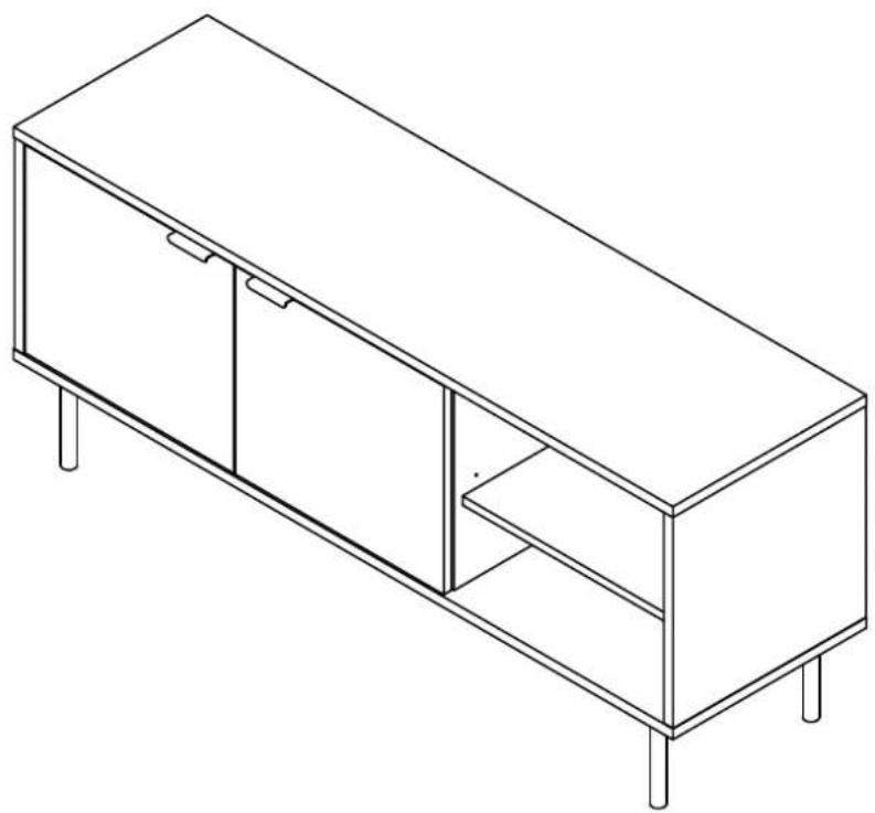
Record Storage Sideboard CF1144
natural_image
Line drawing of a modern rectangular cabinet with four legs and three doors, no text or symbols presentPARTS LIST
| A2 | 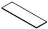 | B2 |  | C2 |  | D2 | E2 | 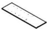 |
| Top Panel1 PC | Left Panel1 PC | Partition Panel1 PC | Right Panel1 PC | Bottom Panel1 PC | ||||
| F2 |  | G2 | 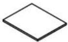 | H | J2 |  | 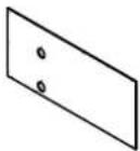 | |
 | ||||||||
| Left Adjustable Shelf1PC | Right Adjustable Shelf1 PC | Left Door1 PC | Right Door1 PC | Left Back Panel1 PC | ||||
| K2 |  | L | 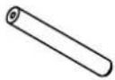 | M |  | N2 |  | O |
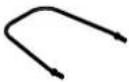 | ||||||||
| Right Back Panel1 PC | Leg4 PCS | Support Leg2 PCS | Cover4 PCS | Metal Wire5 PCS | ||||
HARDWARE LIST
| #1 | #3 #4 #5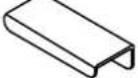 | #2 |  |  |  1/4"*51mm 1/4"*51mm |  1/4"*25mm 1/4"*25mm | |||
| Handle2 PCS | Double Magnet1 PC | Shelf Holder8 PCS (Extra 1) | Long Bolt6 PCS (Extra 1) | Round Head Bolt6 PCS (Extra 1) | |||||
| #6 | #7 #8 #9 #101/4"*25mm | 1/4"*16mm | 1/4"*10mm 1/4"*1 | 3mm 8*30mm | |||||
| Medium Bolt6 PCS (Extra 1) | Short Bolt18 PCS (Extra 1) | Spring Washer12 PCS (Extra 1) | Flat Washer12 PCS (Extra 1) | Wood Dowel12 PCS (Extra 1) | |||||
| #11 | #12 | #13 #14 #15M4 | 6*3*15mm | 6*3*15mm | 8*3*12mm | ||||
| Barrel Nut6 PCS (Extra 1) | Hex Nut10 PCS (Extra 1) | Long Screw4 PCS (Extra 1) | Round Head Screw2 PCS (Extra 1) | Short Screw29 PCS (Extra 1) | |||||
| #16 | #17 | #19 #20 | #18 | M4 | M2 | ||||
| Binding Post4 SETS (Extra 1) | Connecting Bar6 PCS | Allen Wrench1 PC | Small Allen Wrench1 PC | Wrench1 PC | |||||
ADDITIONAL TOOLS (Not Provided)
Note: It is not recommended to use power tools during assembly.

Phillips Head Screwdriver
Note: Wood dowels are intended for alignment. Additional clearance between wood dowel and pre-drilled hole is intentional for ease of assembly.
Step 1. Attach double magnet (part #2) to top panel (part A2) using round head screws (part #14) and phillips head screwdriver.

Step 2. Attach connecting bars (part #17) to legs and support legs (parts L & M) using medium bolts (part #6) and allen wrench (part #18).
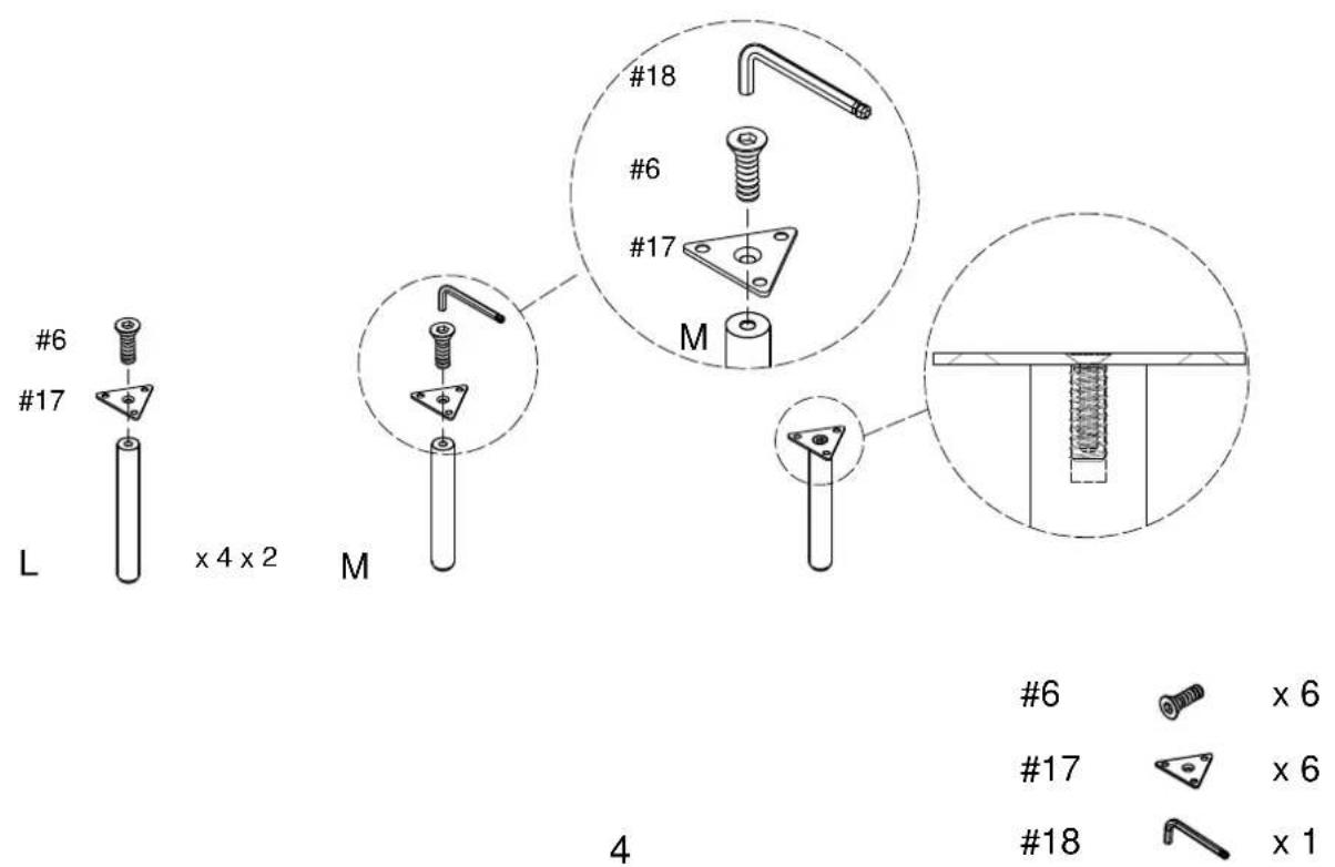
Step 3. Attach legs and support legs (parts L & M) to bottom panel (part E2) using short bolts (part #7) and allen wrench (part #18).

Step 4. Attach covers (part N2) to back panels (parts J2 & K2) using binding posts (part #16) and small allen wrench (part #19).

Step 5. Attach handles (part #1) to doors (parts H & I) using long screws (part #13) and phillips head screwdriver.

1

x 2
13

x 4
Step 6. Attach panels (parts B2, C2 & D2) to top panel (part A2) using wood dowels (part #11), round head bolts (part #5), spring washers (part #8), flat washers (part #9) and allen wrench (part #18).

5

x 6
8

x 6
9

x 6
10

x 6
18

x 1
Step 7. Attach bottom panel (part E2) to assembled unit (parts B2, C2 & D2) using wood dowels (part #10), barrel nuts (part #11), long bolts (part #4), spring washers (part #8), flat washers (part #9) and allen wrench (part #18).


Step 8. Attach back panels (parts J2 & K2) to assembled unit (parts A2, B2, C2, D2 & E2) using short screws (part #16) and phillips head screwdriver.

16

x 29
Step 9. There are two installation options for door storage. Installation wire metal or adjustable shelf.
Insert shelf holders (part #3) and slide left adjustable shelf (part F2) into place.

3

x 4
OR
Carefully put the unit down. Attach metal wires (part O) to bottom panel (part E2) using hex nuts (part #12) and wrench (part #20).

Step 10. Attach doors (parts H & I) by placing pin hinge (pre-installed in door) in the pre-drilled hole of bottom panel (part E2). Then depress the top spring-loaded pin hinge so it can be placed in the pre-drilled hole of top panel (part A2).
NOTE: Be sure top and bottom pin hinges are fully extended to secure doors in place.
NOTE: It is important to adjust levelers once fully assembled and upright. Extend adjustable leveler until it's firmly in contact with the floor. if relocating, adjust leveler as needed until it's firmly in contact with the floor in new location.

Step 11. Insert shelf holders (part #3) into desired position and slide right adjustable shelf (part G2) into place.

3

x 4
Brand : Crosley
Model : Brody CF1144
Category : Radio