
Kenji CF1146 - Storage furniture Crosley - Free user manual and instructions
Find the device manual for free Kenji CF1146 Crosley in PDF.

| Product Type | Cabinet (Two-Door Display/Storage) |
| Brand | Crosley |
| Model | Kenji CF1146 |
| Assembly Required | Yes (Full Assembly) |
| Recommended Tools | Phillips Head Screwdriver (Power tools not recommended) |
| Number of Pieces | 15 panels + hardware |
| Hardware Included | Screws, Bolts, Washers, Wood Dowels, Handles, Magnets, Shelf Holders, Safety Strap Kit |
| Anti-Tip Device | Safety Strap Kit Included (Must be installed) |
| Door Type | Two hinged doors with mesh windows and arched cutouts |
| Door Closure | Double magnets (pre-installed on doors) |
| Shelf | 1 adjustable shelf with 5 shelf holders |
| Legs/Levelers | 1 support leg with adjustable levelers |
| Back Panels | 3 separate back panels covered with decorative covers |
| Metal Wire Supports | 5 wires attached to bottom panel |
| Application | For display or storage (Not intended for clothing storage) |
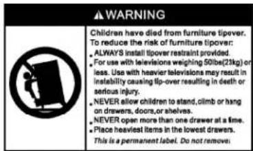
| Safety Warning | Must be secured to wall to prevent tipping |
| Country of Origin | Not specified |
| Warranty | Refer to manufacturer |
Frequently Asked Questions - Kenji CF1146 Crosley
User questions about Kenji CF1146 Crosley
0 question about this device. Answer the ones you know or ask your own.
Ask a new question about this device
Download the instructions for your Storage furniture in PDF format for free! Find your manual Kenji CF1146 - Crosley and take your electronic device back in hand. On this page are published all the documents necessary for the use of your device. Kenji CF1146 by Crosley.
USER MANUAL Kenji CF1146 Crosley
natural_image
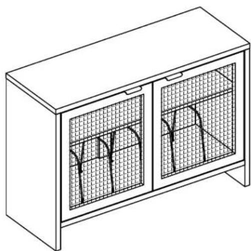
Line drawing of a two-door cabinet with mesh windows and arched cutouts (no text or symbols)PARTS LIST
| A |  | B |  | C |  | D2 | E2 |  |
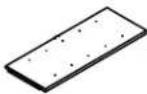 | ||||||||
| Top Panel1 PC | Left Panel1 PC | Right Panel1 PC | Bottom Panel1 PC | Adjustable Shelf1 PC | ||||
| F | 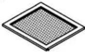 | G | [g3c3] | H2 | I2 J2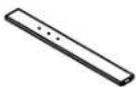 | 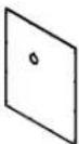 | ||
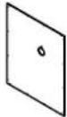 | ||||||||
| Left Door1PC | Right Door1 PC | Middle Back Panel1 PC | Left Back Panel1 PC | Right Back Panel1 PC | ||||
| K |  | L2 |  | M | 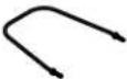 | |||
| Support Leg1 PC | Cover2 PCS | Metal Wire5 PCS | ||||||
HARDWARE LIST
| #1 | #3 #4 #5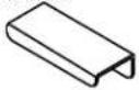 | #2 |  |  |  1/4"*32mm 1/4"*32mm |  1/4"*11mm 1/4"*11mm | |||
| Handle2 PCS | Double Magnet2 PCS | Shelf Holder5 PCS (Extra 1) | Round Head Bolt8 PCS (Extra 1) | Spring Washer8 PCS (Extra 1) | |||||
| #6 | #7 #8 #9 #101/4"*13mm |  8*30mm 8*30mm | [97T4]M4 | [77A0]6*3*15mm |  6*3*15mm 6*3*15mm | ||||
| Flat Washer8 PCS (Extra 1) | Wood Dowel12 PCS (Extra 1) | Hex Nut10 PCS (Extra 1) | Long Screw4 PCS (Extra 1) | Round Head Screw4 PCS (Extra 1) | |||||
| #11 |  8*3*12mm 8*3*12mm | #12 | #13 #14 #15 | 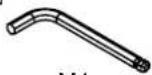 M4 M4 | [0442]M2 |  | |||
| Short Screw32 PCS (Extra 1) | Binding Post2 SETS (Extra 1) | Allen Wrench1 PC | Small Allen Wrench1 PC | Wrench1 PC | |||||
| #16 |  | ||||||||
| Safety Strap Kit1 SET | |||||||||
ADDITIONAL TOOLS (Not Provided)
Note: It is not recommended to use power tools during assembly.
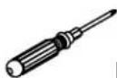
Phillips Head Screwdriver
Note: Wood dowels are intended for alignment. Additional clearance between wood dowel and pre-drilled hole is intentional for ease of assembly.
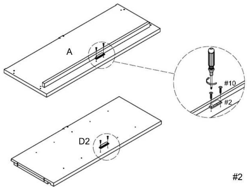
Step 1. Attach double magnets (part #2) to panels (parts A & D2) using round head screws (part #10) and phillips head screwdriver.
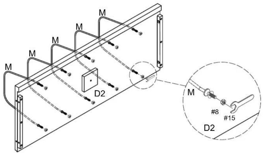
Step 2. Attach metal wires (part M) to bottom panel (part D2) using hex nuts (part #8) and wrench (part #15).

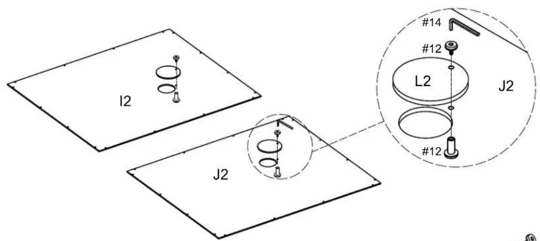
Step 3. Attach covers (part L2) to back panels (parts I2 & J2) using binding posts (part #12) and small allen wrench (part #14).
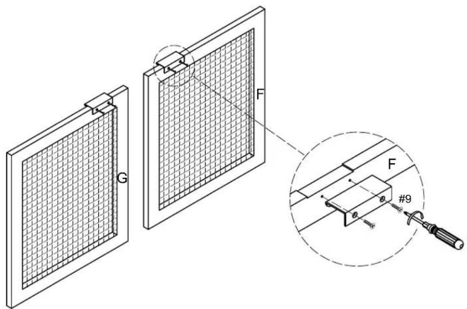
Step 4. Attach handles (part #1) to doors (parts F & G) using long screws (part #9) and phillips head screwdriver.
1

x 2
9

x 4
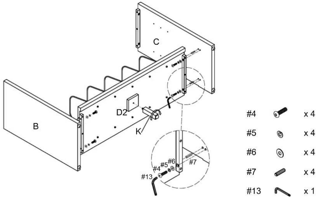
Step 5. Attach panels (parts B & C) to bottom panel (part D2) using wood dowels (part #7), round head bolts (part #4), spring washers (part #5), flat washers (part #6) and allen wrench (part #13). Attach support leg (part K) to bottom panel (part D2).
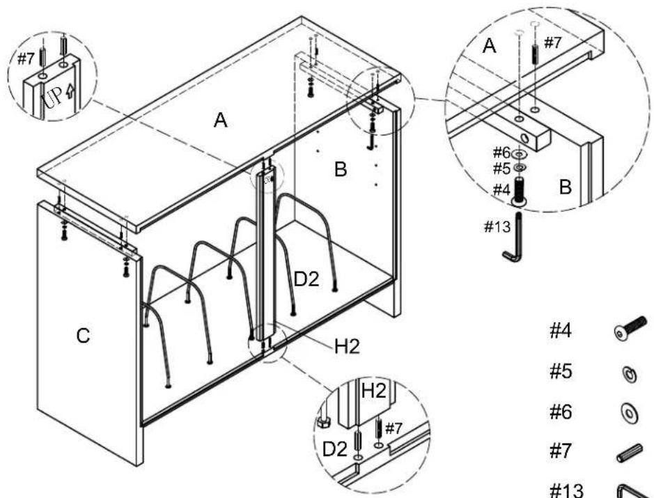
Step 6. Carefully turn assembled unit upright. Attach panels (parts A & H2) to assembled unit (parts B, C & D2) using wood dowels (part #7), round head bolts (part #4), spring washers (part #5), flat washers (part #6) and allen wrench (part #13).
Step 7. Attach back panels (parts I2 & J2) to assembled unit (parts A, B, C, D2 & H2) using short screws (part #11) and phillips head screwdriver.
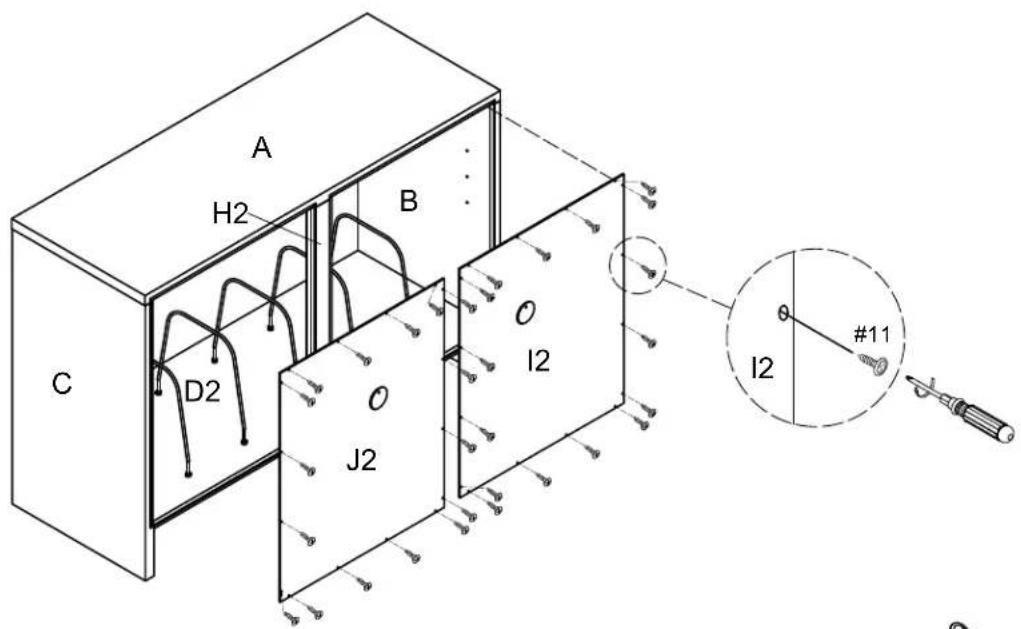
11

x 32
Step 8. Insert shelf holders (part #3) and slide adjustable shelf (part E2) into place.
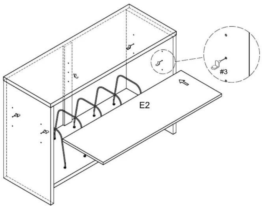
3

× 5
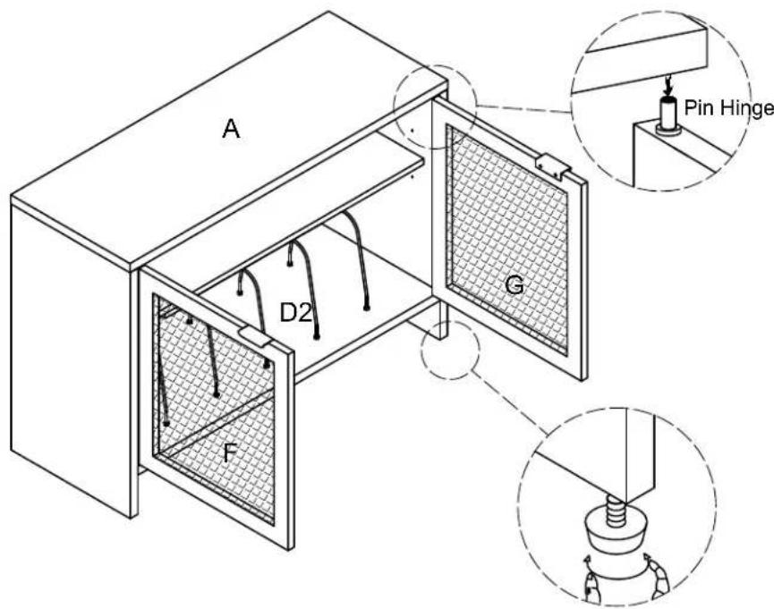
Step 9. Attach doors (parts F & G) by placing pin hinge (pre-installed in door) in the pre-drilled hole of bottom panel (part D2). Then depress the top spring-loaded pin hinge so it can be placed in the pre-drilled hole of top panel (part A).
NOTE: Be sure top and bottom pin hinges are fully extended to secure doors in place.
NOTE: It is important to adjust levelers once fully assembled and upright. Extend adjustable leveler until it's firmly in contact with the floor. If relocating, adjust leveler as needed until it's firmly in contact with the floor in new location.
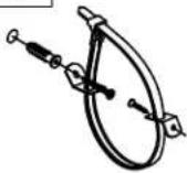
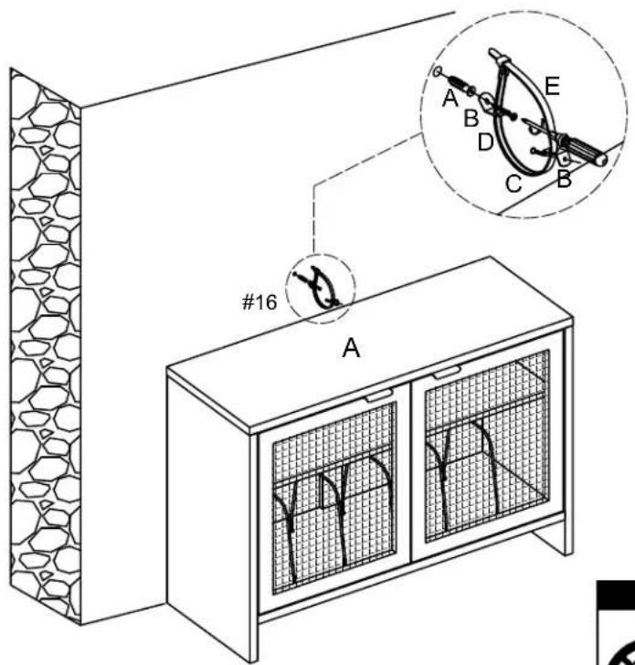
Important: Safety strap kit (part #16) must be installed to prevent tipping damage and/or injury.
natural_image
Line drawing of a two-door cabinet with mesh windows and curved internal structures (no text or symbols)| #16 | A | B | C | D | E |
 |  |  |  8*3*15mm 8*4*35mm 8*3*15mm 8*4*35mm |  |  |
| Safety Strap Kit1 SET | Wall Anchor1 PC | Bracket2 PCS | Short Screw1 PC | Long Screw1 PC | Safety Wall Strap1 PC |
SAFETY WALL STRAP INSTALLATION
Note: It is highly recommended to install this safety strap kit to prevent tipping, damage and/or injury.
- Insert short screw (C) and safety wall strap (E) through bracket (B) and attach to top panel (part A) using phillips head screwdriver.
- Drill a 11/32" hole where you want to secure the unit. The drilled hole will be at the same height as the hole in top panel (part A) where bracket (B) is attached. Tap wall anchor (A) into the hole.
- Insert long screw (D) and safety wall strap (E) through bracket (B) into wall anchor (A) using phillips head screwdriver.
Note: This item is not intended for clothing storage use.


Brand : Crosley
Model : Kenji CF1146
Category : Storage furniture