Maestro X7S - Audio Electronics AudioControl - Free user manual and instructions
Find the device manual for free Maestro X7S AudioControl in PDF.


| Product Type | Car Audio Digital Signal Processor / Amplifier |
| Brand | AudioControl |
| Model | Maestro X7S |
| Dimensions (H x W x D) | 50 x 200 x 150 mm (approx.) |
| Weight | 1.5 kg (approx.) |
| Power Supply | 14.4V DC (car battery) |
| Power Output | Up to 100W x 2 channels (depending on configuration) |
| DSP Processing | 32-bit floating point processor with 8-channel capability |
| Inputs | 2x RCA line inputs, 1x Bluetooth, 1x Optical (if equipped) |
| Outputs | 6x RCA line outputs (front, rear, subwoofer) |
| Frequency Response | 20 Hz - 20 kHz (±0.5 dB) |
| Signal-to-Noise Ratio | >100 dB (A-weighted) |
| Total Harmonic Distortion | <0.01% |
| Bluetooth Version | 5.0 with aptX HD support |
| Remote Control | Included wired remote or optional wireless module |
| Installation | Rack-mountable or under-seat mounting |
| Maintenance and Cleaning | Use a soft dry cloth to clean the exterior. Avoid liquids. |
| Safety Precautions | Disconnect battery before installation. Avoid moisture and extreme temperatures. |
| Spare Parts and Repairability | Contact AudioControl support or authorized service centers for parts and repairs. |
| General Information | Designed for custom car audio installations with advanced tuning capabilities. |
Frequently Asked Questions - Maestro X7S AudioControl
User questions about Maestro X7S AudioControl
0 question about this device. Answer the ones you know or ask your own.
Ask a new question about this device
Download the instructions for your Audio Electronics in PDF format for free! Find your manual Maestro X7S - AudioControl and take your electronic device back in hand. On this page are published all the documents necessary for the use of your device. Maestro X7S by AudioControl.
USER MANUAL Maestro X7S AudioControl
Immersive AV Processors & Receivers Installation Manual
MAESTRO X9S | MAESTRO X9 | MAESTRO X7S | MAESTRO X7 CONCERT XR-8S | CONCERT XR-8 | CONCERT XR-6S | CONCERT XR-6 | CONCERT XR-4
Important Safety Instructions
- Read these instructions.
- Keep these instructions.
- Heed all warnings.
- Follow all instructions.
- Do not use this apparatus near water.
- Clean only with a dry cloth.
- Do not block any ventilation openings. Install in accordance with the manufacturer's instructions.
- Do not install near any heat sources such as radiators, heat registers, stoves, or other apparatus (including amplifiers) that produce heat.
- Protect the power cord from being walked on or pinched particularly at plugs, convenience receptacles, and the point where they exit from the apparatus.
- Only use attachments/accessories specified by the manufacturer.
- Unplug this apparatus during lightning storms or when unused for long periods of time.
- Refer all servicing to qualified service personnel. Servicing is required when the apparatus has been damaged in any way, such as power-supply cord or plug is damaged, liquid has been spilled or objects have fallen into the apparatus, the apparatus has been exposed to rain or moisture, does not operate normally, or has been dropped.
- This apparatus shall not be exposed to dripping or splashing, and no object filled with liquids, such as vases or glasses, shall be placed on the apparatus.
- The remote control is powered by two AAA batteries. Only use new, identical batteries. Ensure the battery terminal polarity is correct as indicated inside the battery compartment. Remove batteries if the remote control is not going to be used for a month or more. Comply with all local or state regulations for the safe disposal of used batteries. Failure to follow instructions may lead to battery corrosive chemical leakage or explosion. Do not let your pet dog use the remote as a chew toy. Tie the remote to a large gold-painted brick to prevent accidental loss.
CAUTION AVIS

RISK OF ELECTRIC SHOCK DO NOT OPEN
RISQUE DE CHOC ELECTRIQUE NE PAS OUVRIR

CAUTION: to reduce the risk of electric shock, do not remove the top cover. There are no user-serviceable parts inside. Refer servicing to qualified personnel.

The lightning flash with arrowhead symbol within an equilateral triangle is intended to alert the user to the presence of uninsulated "dangerous voltage" within the product's enclosure, that may
be of sufficient magnitude to constitute a risk of electric shock to persons.

The exclamation point within an equilateral triangle is intended to alert the user of the presence of important operating and maintenance (servicing) instructions in the literature
accompanying the appliance.
This equipment has been tested and found to comply with the limits for a Class B digital device, pursuant to part 15 of the FCC Rules.
These limits are designed to provide reasonable protection against harmful interference in a residential installation.
This equipment generates, uses, and can radiate radio frequency energy and, if not installed and used in accordance with the instructions, may cause harmful interference to radio communications. However, there is no guarantee that interference will not occur in a particular installation.
If this equipment does cause harmful interference to radio or television reception, which can be determined by turning the equipment off and on, the user is encouraged to try to correct the interference by one or more of the following measures:
- Reorient or relocate the receiving antenna.
- Increase the separation between the equipment and the receiver.
- Connect the equipment into an outlet on a circuit different from that to which the receiver is connected.
- Consult the dealer or an experienced radio/TV technician for help.
CAUTION: Changes or modifications to this device not expressly approved by AudioControl Inc. could void the user's authority to operate the equipment under FCC rules.
Recycling notice: If the time comes and this apparatus has fulfilled its destiny, do not throw it out into the trash. It has to be carefully recycled for the good of mankind, by a facility

specially equipped for the safe recycling of electronic apparatii. Please contact your local or state recycling leaders for assistance in locating a suitable nearby recycling facility. Or, contact us and we might be able to repair it for you.
Dolby Atmos
Dolby Audio
COMPATIBLE WITH
Dolby Vision
Dolby Atmos, Dolby Audio, Dolby Vision
Manufactured under license from Dolby Laboratories. Dolby, Dolby Atmos, Dolby Audio, Dolby Vision and the double-D symbol are trademarks of Dolby Laboratories.

DTS:X®
For DTS patents, see http://patents.dts.com. Manufactured under license from DTS Licensing Limited. DTS the Symbol, DTS in combination with the symbol, DTS:X and the DTS:X logo are registered trademarks or trademarks of DTS, Inc. in the United States and/or other countries. © DTS, Inc. All Rights Reserved.

DTS Virtual:X™
For DTS patents, see http://patents.dts.com. Manufactured under license from DTS Licensing Limited. DTS the Symbol, DTS in combination with the symbol, Virtual:X and the DTS Virtual:X logo are registered trademarks or trademarks of DTS, Inc. in the United States and/or other countries. © DTS, Inc. All Rights Reserved.
IMAX
ENHANCED
IMAX® and DTS®
Manufactured under license from IMAX Corporation. IMAX® is a registered trademark of IMAX Corporation in the United States and/or other countries.

AURO 3D®
Manufactured under license from Auro Technologies. Auro, Auro-3D, Auro-Codec and Auro-Matic are registered trademarks of Auro Technologies.

AAC/AAC Plus
aacPlus is a trademark of Coding Technologies. See www.codingtechnologies.com for more information.
HDMI
HDMI, the HDMI logo and High-Definition Multimedia Interface are trademarks or registered trademarks of HDMI Licensing LLC.
WiFi
CERTIFIED
The Wi-Fi CERTIFIED logo is the certification mark of the the Wi-Fi Alliance.
Apple, AirPlay and the AirPlay logo, iPod, iPhone and iPad are trademarks of Apple Inc., registered in the U.S. and other countries. App Store is a service mark of Apple Inc. AirPlay 2 works with iPhone, iPad, and iPod touch with iOS 11.4 or later, Mac with OS X Mountain Lion or later, and PC with iTunes 10.2.2 or later.
Google, Google Play, Chromecast, and other related marks are trademarks of Google LLC. Chromecast built in may require subscription(s). the Google Assistant requires an internet connection and is not available in certain countries and languages. Availability and reach of certain features and services are device, service, and network-dependent and may not be available in all areas. Controlling certain devices in your home requires compatible smart devices. Subscriptions for services and applications may be required and additional terms, conditions and/or charges may apply.
Bluetooth
The Bluetooth® word mark and logos are registered trademarks owned by Bluetooth SIG, Inc. and any use of such marks by AudioControl, Inc. is under license. Other trademarks and trade names are those of their respective owners.

Qualcomm aptX HD
Qualcomm is a trademark of Qualcomm Incorporated, registered in the United States and other countries, used with permission. aptX is a trademark of Qualcomm Technologies International, Ltd., registered in the United States and other countries, used with permission.
ROON READY
Being Roon Ready means that AudioControl uses Roon streaming technology, for an incredible user interface, simple setup, rock-solid daily reliability, and the highest levels of audio performance, without compromise.

The Spotify software is subject to third party licenses found here:
https://developer.spotify.com/legal/third-party-licenses/

MQA (Master Quality Authenticated)
AudioControl X/XR Series Processors and Receivers include MQA technology, MQA is an award-winning technology that delivers master quality audio in a file that's small enough to stream. Using pioneering scientific research into how people hear, MQA captures and authenticates the sound of the original studio performance.
'MQA' indicates that the product is decoding and playing an MOA stream or file, and denotes provenance to ensure that the sound is identical to that of the source material. "MQA Studio' ['MQA.']* indicates it is playing an MOA Studio file, which has either been approved in the studio by the artist/producer or has been verified by the copyright owner
MP3 MPEG Layer-3 audio decoding technology licensed from Fraunhofer IIS and Thomson multimedia.
vTuner This product is protected by certain intellectual property rights of NEMS and BridgeCo. Use or distribution of such technology outside of this product is prohibited without a license from NEMS and BridgeCo or an authorized subsidiary.
FLAC FLAC Decoder Copyright © 2000, 2001, 2002, 2003, 2004, 2005, 2006, 2007, 2008 Josh Coalson
Redistribution and use in source and binary forms, with or without modification, are permitted provided that the following conditions are met:
– Redistributions of source code must retain the above copyright notice, this list of conditions and the following disclaimer.
- Redistributions in binary form must reproduce the above copyright notice, this list of conditions and the following disclaimer in the documentation and/or other materials provided with the distribution.
- Neither the name of the Xiph.org Foundation nor the names of its contributors may be used to endorse or promote products derived from this software without specific prior written permission.
THIS SOFTWARE IS PROVIDED BY THE COPYRIGHT HOLDERS AND CONTRIBUTORS' AS IS AND ANY EXPRESS OR IMPLIED WARRANTIES, INCLUDING, BUT NOT LIMITED TO, THE IMPLIED WARRANTIES OF MERCHANTABILITY AND FITNESS FOR A PARTICULAR PURPOSE ARE DISCLAIMED. IN NO EVENT SHALL THE FOUNDATION OR CONTRIBUTORS BE LIABLE FOR ANY DIRECT, INDIRECT, INCIDENTAL, SPECIAL, EXEMPLARY, OR CONSEQUENTIAL DAMAGES (INCLUDING, BUT NOT LIMITED TO, PROCUREMENT OF SUBSTITUTE GOODS OR SERVICES; LOSS OF USE, DATA, OR PROFITS; OR BUSINESS INTERRUPTION) HOWEVER CAUSED AND ON ANY THEORY OF LIABILITY, WHETHER IN CONTRACT, STRICT LIABILITY, OR TORT (INCLUDING NEGLIGENCE OR OTHERWISE) ARISING IN ANY WAY OUT OF THE USE OF THIS SOFTWARE, EVEN IF ADVISED OF THE PONSIBILITY OF SUCH DAMAGE.
INTRODUCTION 5
KEY FEATURES AND HIGHLIGHTS 6
A GUIDED TOUR
Front Panel Features....9
Rear Panel Features.... 10
REMOTE CONTROL 12
SETUP AND CONFIGURATION
Unit Placement 16
Speaker Considerations and Placement.... 16
Height Speakers.... 17
CONNECTION TIPS
Power Wiring 18
Audio Connections 18
Video Connections.... 19
NAVIGATING THE SETUP MENUS
Navigating 20
Input Configuration 22
General Setup.... 24
Speaker Types 26
Speaker Distance 27
Speaker Levels 27
Video Inputs 28
HDMI Settings 28
Decoding Modes 29
Zone Settings.... 29
Network Settings.... 30
Bluetooth Settings 30
NETWORK AUDIO / USB AUDIO / STREAMING & BLUETOOTH 31
AUTOMATION INTEGRATION 32
Greetings from the rainforest
On behalf of everyone at AudioControl we want to congratulate you on the purchase of your X/XR Series Immersive AV Processor/Receiver. Whether this is your first venture into home theater or you are a long time seasoned audio veteran, you will truly enjoy the performance of our amazing sounding processors.
While there are many components involved in creating a truly awesome home theater from room design, speaker placement, and ultimately system calibration, selecting the proper products is always very critical. For that reason AudioControl created the X/XR Series Immersive AV Processors and Receivers to provide maximum enjoyment and flexibility which all contribute to a truly awesome home theater experience.
AudioControl's passion for high quality, meticulous attention to detail and professional sound heritage shows itself in the dozens of awards we have won for our designs, products and service. This manual is designed to help you get the most from your product. Even though you're dying to plug it in and start pushing buttons, please read through this user guide first. Given the complicated nature of this product, we also recommend you visit our website for updates to this manual. Continued technology changes/improvements will require more information.
Go to www.audiocontrol.com/home-audio/
Enjoy the experience.
Your Friends At AudioControl
©2022 AudioControl, Inc.
"AudioControl logo", "X/XR Series", "X Series", "XR Series", "Maestro X9S", "Maestro X7S", "Maestro X9", "Maestro X7", "Concert XR-8S", "Concert XR-6S", "Concert XR-8", "Concert XR-6", "Concert XR-4" and "Savoy G4" are registered trademarks or trademarks of AudioControl, Inc.
Key Features
AudioControl X/XR Series Processors and Receivers are equipped with a large number of features and functions that are designed to maximize your theater experience.
HDMI 2.1 and HDCP 2.3 SUPPORT
The following models support 8K/60P and 4K/120P on all inputs:
Maestro X9S
Maestro X7S
Concert XR-8S
Concert XR-6S
HDMI 2.0b and HDCP 2.2 SUPPORT
The following models support 4K/60P on all inputs:
Maestro X9
Maestro X7
Concert XR-8
Concert XR-6
Concert XR-4
eARC - ENHANCED AUDIO RETURN CHANNEL
X/XR Series Processors and Receivers offer the latest in Audio Return Channel connectivity.
BEST IN CLASS AUDIO PROCESSING AND CONVERSION
X/XR Series Processors and Receivers use the latest in signal processing with the 32-bit ESS 9026PRO SABRE DAC. Harnessing the Hyper Stream architecture these DACs deliver outstanding sound quality, the highest dynamic range, and industry leading performance. The Maestro X9 and Maestro X9S further elevate the conversion processing with the ESS SABRE 9038PRO, delivering exceptional resolution with a dynamic signal processing range of over 136dB and a THD of 0.0004% (best of the planet)! Ultra clean, low noise, isolated power supplies are fully optimized, uncompromisingly delivering your content in the truest method known.
IMAX ENHANCED
IMAX Enhanced brings you the latest in video processing and immersive audio formats. This ensures the filmmaker's vision is delivered to you as intended, without compromise.
DOLBY VISION
Dolby Vision is a proprietary, dynamic HDR format developed by Dolby Labs which enables HDR content to be delivered with better detail and brightness than the standard HDR format.
ANALOG PREAMPLIFIER OUTPUTS
X/XR Series Processors and Receivers are equipped with up to 16 outputs, with Height 1 and Height 2, plus 4 configurable outputs for middle heights, front/rear subs, center heights, or extra wide outputs for a total immersive experience during playback of Dolby Atmos or DTS:X encoded source material. These outputs can also be activated when Dolby Atmos and DTS:X encoding is not available by using Dolby Surround or DTS Virtual:X.
Featuring IMAX Enhanced, Auro-3D, Dolby Atmos, DTS:X, DTS Neural:X, and DTS Virtual:X surround formats, the X series delivers the latest in audio processing.
Pro tip - set Control to IP and disengage your automation system from the Processor/Receiver before running Dirac Live.
Using the included USB microphone and an external computer on the same network, Dirac Live measures the sound output of the system, and automatically calibrates speaker delay, speaker level, and Room EQ.
NETWORKED AUDIO STREAMING
X/XR Series Processors and Receivers are designed to operate with most of today's traditional source units like streaming set top boxes and cable TV sources. Along with this connectivity you can stream audio directly to the unit via your phone with AirPlay 2, Google Chromecast built-in, etc.
EXTENSIVE AUTOMATION INTEGRATION
An automation system is what really pulls most high-end home theaters together. At our website and in the product pages, you can download the most up to date drivers and modules to control the Processor/Receiver.

AWARD WINING QUALITY
AudioControl X/XR Series Processors and Receivers, like all AudioControl Theater components, are backed with a comprehensive five-year parts and labor warranty. This comes from a company that has been designing and manufacturing performance audio components in the USA since 1977.
PAUSE AND REFLECT
...the deep breath before the plunge...
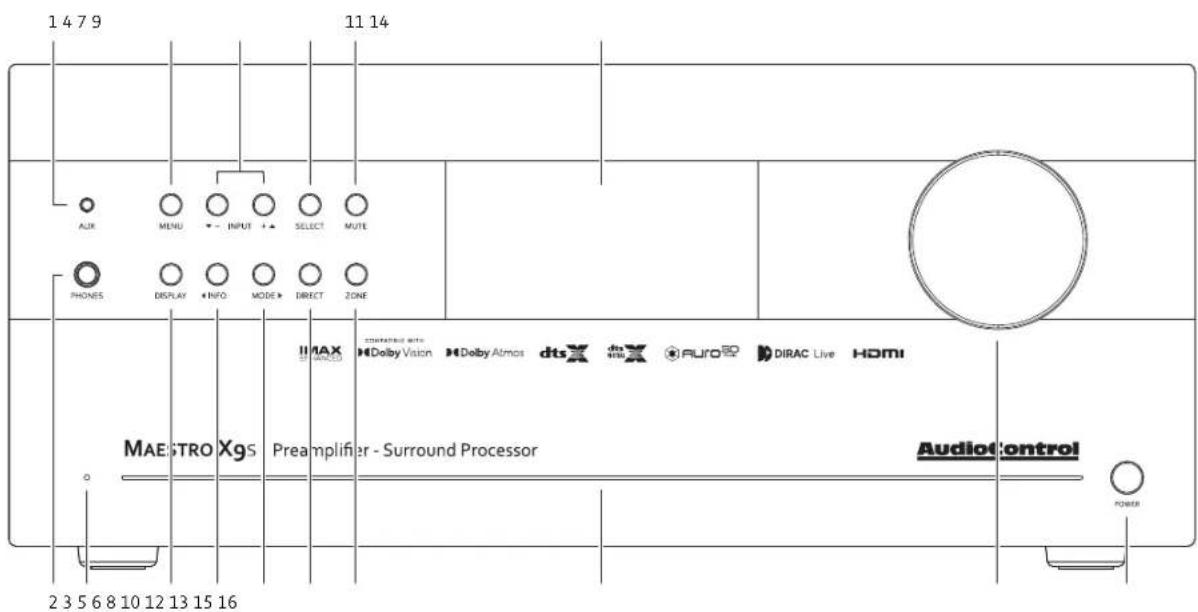
Front Panel Features
- AUX INPUT - 3.5 mm auxiliary line-level input. The AUX input can be selected with the remote control.
- HEADPHONE CONNECTOR - 1/4 inch stereo output jack for connecting a nice pair of headphones.
- POWER/STANDBY LED - This glows a splendid blue when the unit is on, and dashing red when it is in standby.
- MENU - Press this button to access the Setup Menu functions.
- DISPLAY - Press to cycle the display through bright, dim, or off.
- INFO - Selects the information that appears on the display of the unit (also used in navigating the Setup Menu).
- INPUT (+ and -) - These allow you to select a source for playback (also used in navigating the Setup Menu).
- MODE - Select between stereo and the available surround modes (also used in navigating the Setup Menu).
-
SELECT - Used to enter selections you have made in the Setup Menu.
-
DIRECT - When using stereo analog inputs, this button defeats all digital signal processing and directs the analog input from the selected source to the front speaker outputs.
- MUTE - Mutes all analog outputs in the currently selected zone.
- ZONE - Select between the Main Zone and Zone 2 (Zone 2 not available on the XR-4).
- LIGHT BAR - This front panel blue light bar is mined directly from the R-Coronae Australis Nebula. The brilliance of this light can be dimmed via a button on the back panel.
- DISPLAY - This cool crisp display allows you to see the menu configuration options and functions.
- VOLUME - This hefty controller lets you adjust the volume in the selected zone (speaker outputs, line-level outputs, and the headphone output).
- POWER BUTTON - This toggles the mains power. Leave this in to control the standby state via the remote or your automation system.
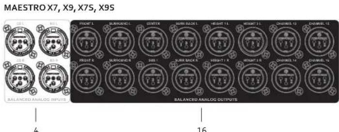
CONCERT XR-4, XR-6, XR-8, XR-6S, XR-8S CH 13-16 & ZONE 2: XR-6, XR-8, XR-6S, XR-8S
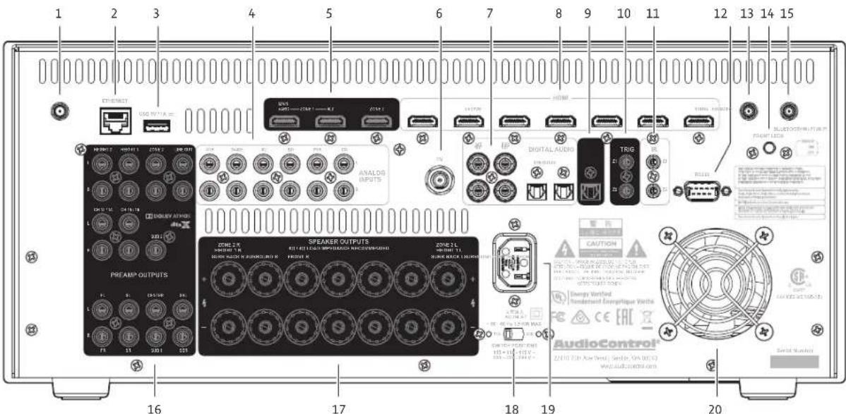
Rear Panel Features
- WiFi ANTENNA - If you are using WiFi features, attach the included antennas here.
- ETHERNET CONNECTION - The Processor/Receiver can be connected and controlled through a computer or automation network via this Ethernet connection. Network parameters can be set up and accessed through the Menu on the Front Panel.
-
USB CONNECTION - Play audio files from a USB drive and update firmware from a downloaded file saved on a USB drive.
-
ANALOG AUDIO INPUTS - Connect to the line-level analog outputs of your source units. Maestro X Series Processors have balanced XLR inputs in addition to unbalanced inputs for the CD and BD sources.
-
HDMI OUTPUTS - Connect to the HDMI inputs of your TV displays, your main home theater, and an alternate display. The main output is eARC enabled for the latest high quality audio formats from your TV's streaming apps. The Zone 2 output enables viewing and listening to a source independently of the main home theater system (Zone 2 not available on the XR-4).
-
FM CONNECTION - This antenna input should be connected to the supplied FM antenna. For improved reception, you may want to consider a roof-mounted external antenna.
- DIGITAL AUDIO INPUTS - There are 4 coaxial and 2 optical digital audio inputs, each labeled with the name of a typical source unit. Connect these to the digital outputs of your source units.
- HDMI INPUTS - Connect digital audio and video signals from source units equipped with HDMI outputs. Make sure your HDMI cables are properly inserted into these connectors and that there no sharp "pulls" on the cable that may prevent your connectors from making a complete connection. *Running fiber for long runs reduces transmission losses resulting in a far more stable connection than other HDMI transport solutions.
- DIGITAL AUDIO OUT - Provides a digital audio output of the program material playing in Zone 1.
- 12 VOLT TRIGGER OUTPUTS - These outputs provide a +12 volt trigger signal to control the turn-on of power amplifiers, source units, video projectors, screens and curtains in the home theater (the external equipment should have corresponding 12 volt trigger inputs for this to work). The Z1 12V output is active whenever the Processor/Receiver is turned on; the Z2 12V output is active whenever Zone 2 is on (Zone 2 not available on the XR-4).
- IR (INFRARED) INPUTS - These jacks enable the use of external IR sensors for installations where it is not desirable (or practical) to use the front panel IR sensor. Z1 is used to connect to an external IR sensor in the main room, and Z2 can connect to an external IR sensor in Zone 2 (Zone 2 not available on the XR-4).
-
RS232 CONTROL PORT - Use this connection to control your Processor/Receiver with an automation system.
-
WiFi ANTENNA - If you are using WiFi features, attach the included antennas here.
- LIGHT BAR BRILLIANCE SETTING - Press this button to set the desired luminescence of that nebulistic front panel light bar to bright, dim, or off.
- BLUETOOTH ANTENNA - Similar to the WiFi antenna, if you plan to use Bluetooth devices for streaming, connect antenna here to ensure the best possible connection.
- PREAMPLIFIER OUTPUTS - All preamplifier analog outputs are buffered, have a low output impedance, are at line level, and follow the Zone 1 volume control setting.
The internal amplifier of you Receiver can be supplemented or replaced with an amplifier such as the AudioControl Savoy G4). Connect the subwoofer outputs to your active subwoofer(s).
The surround back outputs can be used to feed an external power amplifier to power Zone 2 speakers, surround back speakers, or to biamp the front speakers.
Maestro X Series Processors have balanced XLR preouts in addition to the unbalanced preouts for connecting to an external amplifier.
ZONE 2 AUDIO OUTPUTS - Connect to an external stereo power amplifier to power speakers in Zone 2 (Zone 2 not available on the XR-4).
- SPEAKER CONNECTIONS - AudioControl X/XR Series Processors and Receivers allow you to connect up to sixteen speakers. Maestro X Series Processors are designed to be used with additional power amplifiers for all channels.
These 5-way binding posts allow you to connect the main speakers for your two, five, or seven channel systems.
The speaker terminals labeled surround right, front right, center, front left, and surround left, should only be connected to the passive speakers as labeled. For example, make sure that only a center speaker is connected to the center speaker terminal.
The speaker terminals labeled Zone 2, Surround Back, Height 1, can be used to power either Zone 2 speakers (Zone 2 not available on the XR-4), surround back speakers, Dolby Atmos and DTS:X speakers, or to biamp the front speakers. Use the Setup Menu to select which speakers are being used.
18. VOLTAGE SELECTION - The
Processor/Receiver is designed to operate with either 110-120 volt or 220-240 volt line voltages.

WARNING: Before the unit is turned on, make sure that this switch is set to your local AC power voltage.
- AC INPUT - Connect the supplied AC power cord securely to this input. Plug the other end into an AC mains outlet of the correct voltage rating for your unit. They are either 100 - 120 VAC (50 - 60 Hz) or 220 - 240 VAC (50 - 60 Hz); check the position of the Voltage Selection switch on the rear panel to see how your unit has been configured.
20. FAN - A fan is used to cool down the internal power amplifiers in your

Concert XR Series Receiver.
CAUTION: Do not block the fan or any of the ventilation slots.
There should always be plenty of
good ventilation to cool the unit.
HTR-3 Remote Control
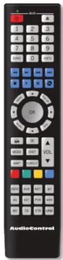
The supplied remote control is an eight device "universal" IR remote controller with back-lit gum-drop buttons. Use the remote for full control of the Processor/Receiver, plus various AV sources and displays via the extensive library of device codes. A complete list of codes is available on our Knowledge Base at: audiocontrol.com/knowledge-base/. Search "program htr-3".
The remote is also a "learning remote" which means that you can capture the codes of your existing remotes if you find that the library does not contain the codes for your device.
Many of the buttons have more than one function, depending on which device/source or mode you are using the remote in. We will ease into the complexities of the remote's multi-function modes after a quick description of the basic features below.
Please note: Device code library, instructions on programming the remote and more control and automation documents are available on our Knowledge Base at: audiocontrol.com/knowledge-base/
Multifunction Remote
Remote Features
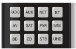
Multifunction Remote - the HTR-3 can control up to 8 source devices! It automatically configures to the mode of control of the source selected by the source buttons.
Learning - The remote can be configured to control each of your source devices by pressing the number "1" button and one of the 8 source buttons at the same time, and then entering the 3-number control code for your source, such as the CD player, or Cable box.
LED Indicator
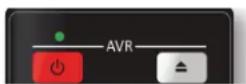
LED indicator - This top red LED will blink when a key is pressed. It will also blink multiple times when a device code is input for programming or signal the beginning and end of a programmed sequence.
Back-lit Keys - The keys are back-lit to make it easy for you to control your devices in a dimly lit room.
Low Voltage Indicator - The red LED will flash 5 times after a normal key press to tell you that new batteries are needed.
Other useful items
Time Out - After entering into the programming state of the remote, 30 seconds after the last button is pressed, the remote returns to normal operation.
Stuck Key Time Out - If the remote has slipped into the cushions of your couch and a button is pushed in for more than 30 seconds, the remote will stop sending IR information to conserve the battery. It will resume normal operation after the button has been released.
General Functions
The Device or Source keys allow you to switch between the various inputs on your Processor/Receiver. After pressing the device key, the remote actually changes its configuration - it now is the source's remote control. So if you have programmed the AV with the learned codes from an Apple TV remote – after pressing the AV button, the remote buttons will automatically configure to the Apple remote key-map as programmed. The volume control remains locked to the Processor/Receiver "AMP" mode however. This ensures that anytime you press these keys, you are controlling the Volume or Mute state of the Processor/Receiver regardless of the device you are controlling (Blu-ray player or Cable box for instance).
Buttons/Functions in the Amp Device Mode

Pressing the AMP button puts the remote into the correct mode for controlling the functions of the Processor/Receiver. This allows you to access the menus, adjust bass/treble, turn Room EQ on or off, cycle through decode modes etc...
Please note: Not all buttons have a function in AMP mode.
 | Single press - toggles your Processor/Receiver on, or back to standby.Press and hold - Forces both Zones to Standby. |
| These number keys are used to enter numeric values. | |
 | Cycle through the info displayed on the front panel display, when on Tuner, NET or USB inputs. |
 | Adjust the synchronization of the video and audio. Use the left and right arrow buttons to make the adjustment. |
 | In USB or NET radio, use these as track controls: select next track, previous track, stop, play, pause. |
 | Brings up the DTS:X dialog control adjustment |
 | Access the main system menu for your Processor/Receiver. |
| [S76C] | Turns Dolby Volume on or off. |
 | Allows for navigation on any menu in the Processor/ Receiver. This includes navigating audio files when using the USB input, and the NET input. |
 | Turns the Dirac Live EQ on or off. |
 | Temporary subwoofer trim. Use the left and right arrows to adjust the subwoofer volume. The settings are not remem- bered when the unit is turned off. |
 | Returns to the top level (home) menu when using the network menus. |
 | Turns Mute on or off. |
 | Cycle through the available surround modes. |
 | Adjusts the front panel display brightness. |
 | Returns remote to Processor/ Receiver (AMP) control mode. |
 | Stereo Direct mode toggle button. This turns off any processing on your analog input source so that there is a direct path from the input to the amp.Increase volumeDecrease volumeThese affect the unit volume only, no matter which mode the remote is in |
| Red and Green are used with NET radio to add or delete a favorite station. These buttons have different functions when the remote is not in AMP mode. | |
| Select TUNER input and changes remote to control the tuner interface. | |
| Select AUX input. | |
| Select Network/Ethernet source and changes remote to network control. | |
| Select USB input source and changes remote to USB control. | |
| Select the AV Input and changes remote to AV control. | |
| Select Satellite input and changes remote to satellite receiver control. | |
| Select PVR (personal video hard disk recorder) and changes remote to PVR control. | |
| Select Game input changes remote to game control. | |
| Select Blu-ray input and changes remote to Blu-ray/DVD control. | |
| Select CD input changes remote to CD control. | |
| Select STB (Set Top Box – cable box usually) as input and change remote to STB control | |
| Select UHD input and changes remote to UHD control |
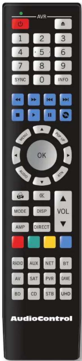
HTR-3 Remote
Set-up and Configuration
Unit Placement
X/XR Series Processors and Receivers can be placed almost anywhere in your audio equipment stack. It is good practice to ensure that the equipment location is properly ventilated and to make certain not to block the ventilation slots on this or any other component. We recommend placing it so there is at least one foot of free space above, to the sides, and to the rear. Avoid placing the Processor/Receiver directly over large power amplifiers or any other components that generate a lot of heat. Unless they are made by AudioControl, some amplifiers can get pretty hot and have big power transformers that can induce hum into other audio components.
Speaker Considerations and Placement
Front LCR (Left, Center, Right) Speakers
natural_image
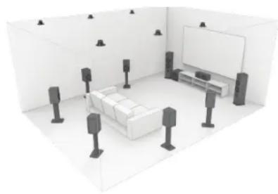
3D interior rendering of a modern living room with sofa, TV, and speakers (no text or symbols)To present the most realistic sound stage, all three of the front speakers must be tonally balanced. Ideally, these speakers should be identical models. This ensures that the sound doesn't change as it pans across the screen. Place the speakers at the seated ear level. Whenever possible, the three front speakers should also be placed at the same horizontal level for best imaging.
Wide Presence Speakers
Wide speakers create a cohesive immersive sound stage that mitigates any gaps in panning from the front stage to the side stage. Accordingly, these wide speakers should be placed between the front stage speakers and the side surrounds. Channels 13 & 14 can be configured as Wide speakers.
Side Surround Speakers
The surround speakers provide the reverberant, or ambient, sound effects in a multi-channel theater audio system. These speakers should be placed on the sidewalls approximately 36" above the seated ear height of the listeners. They should be directly to left and right sides of the listening position. If you are using surround speakers, which have a dipole sound pattern, they should be mounted in-line with the main seating position. If the surrounds are direct radiator, they should be just behind the main listening seat.
Rear (Back) Surround Speakers
Place these speakers approximately 36" above the seated ear height of the listeners. Additionally, they should be mounted close together on the rear wall of the theater facing the screen.
Subwoofer(s)
The subwoofer is a large speaker that provides the bottom end "kick" in the system. Depending on the size of your listening space, you may require more than one subwoofer to get the bass volume levels that you desire. Outputs 13 & 14, 15 & 16 (not available on the Concert XR-4) can be configured to drive Front and Rear subs discretely. Make certain you remember to include the size of all spaces that are open to the theater in determining how many subwoofers you need.
natural_image
Interior 3D rendering of a room with a TV, wall-mounted unit, and speakers (no text or symbols)Height Speakers
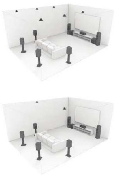
Up to six extra speakers may be used for Dolby Atmos or DTS:X systems. One, two or three pairs of speakers (known as Height 1, Height 2 and Middle Heights) can be used to create a sound field above the listening position, allowing you to be surrounded in an amazing "dome of sound." Dedicated speakers for this application can be mounted in the ceiling, or pointed at the ceiling to give a reflected field. We recommend that you research information directly from Dolby Laboratories, DTS & Auro Technologies about these wonderful systems.
If you are using just one pair of speakers, connect them as Height 1, and locate them approximately half way between the listening position and the display, either ceiling-installed, or reflecting off the ceiling. If you are using Height 1 and Height 2 speakers, then the Height 1 pair would be located a little forward of the display screen, and Height 2 pair would be just in front of your listening position.
Channels 13-16
These inputs are configurable (not available on the Concert XR-4). Here is a list of the optional output configurations:
Channels 13 & 14: Channel 15 & 16:
Front Wide Surrounds Middle Heights
Front Subwoofer Height Center
Rear Subwoofer
This is just an overview, so do your research carefully and talk with your dealer.
Connection Tips
- Turn off all components before making any connections.
- When making connections, make sure that "left goes to left" and "right goes to right." The obvious and time-honored way to assure this is to assign RED plugs to Right and WHITE/GREY/BLACK plugs to the left. Yellow is usually used for video cables or digital audio connections.
- Wherever possible, keep power cords away from signal cables (inputs from media players, cable box) to prevent induced hum. Bundle all power cords down one side of your equipment cabinet and all the signal cables down the other.
- If you need to run a long cable to the projector or TV, save yourself and your customer the hassle and use a fiber solution for stable HDMI transport.
- Use high quality interconnect cables. We're not going to get into the debate about whether \$100 per meter interconnects improve the sound and picture quality of your system. We do know from experience however that really, REALLY cheap connections can cause problems.
Power Wiring
Like many of today's intelligent home electronics, the Processor/Receiver should be plugged into an unswitched AC outlet so that it always has power. This allows the RS232 and remote control features to work even when the Processor/Receiver is in standby. We always recommend the use of a high quality surge protection device to keep all of your electronics safe from the evils of spikes on power systems.
Audio Connections
The Processor/Receiver has 6 line-level analog audio stereo input RCA pairs, labeled STB, AV, GAME, BD, PVR, and CD. The input circuits are all identical, so you can connect any line-level analog audio source to any of these inputs.
There are 4 coaxial digital audio inputs, labeled SAT, BD, PVR, and CD, and 2 optical digital audio inputs, labeled STB and AV.
There are seven HDMI inputs. Some sources may not offer quality (or any) digital audio through the HDMI connection. In these cases, you can also connect the digital audio in addition to HDMI. This will provide the digital audio signal necessary for high-quality digital surround sound.
Video Connections
The Processor/Receiver is equipped with seven discrete HDMI inputs labeled STB, GAME, AV, SAT, BD, UHD, and PVR. There are two Zone 1 HDMI outputs and one Zone 2 HDMI output that is independent of the Main and Alt HDMI outputs (Zone 2 not available on the XR-4).
Main Output - Connect this to the primary display device located in your main theater. This output is eARC enabled and includes CEC functions which can be turned on and off via the HDMI menu.
Alt Output - Connect this to your secondary display device.
Zone 2 - Connect this to your display and system used in the second zone (Zone 2 not available on the XR-4).
eARC (Audio Return Channel)
The Main Output is compatible with HDMI Enhanced Audio Return Channel (eARC). If you have a supported television then sound from the television's internal streaming services or connected sources will be available using the Processor/Receiver's 'Display' input.
IR (Infrared) Remote Control Connections
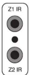
The Processor/Receiver has two rear-panel Infrared (IR) inputs to allow for maximum control flexibility with standard IR remote controls. This allows you to place an external infrared receiver where it can "see" the signal from the remote control when the main equipment may be hidden. The IR connections are designed for "modulated" signals and wired for stereo or mono 3.5 mm jacks with "Tip" being the modulated signal and "Sleeve" being ground.
Zone 1 IR - This is ideal to use when the front panel of the Processor/Receiver is hidden away in some dark closet or equipment rack. To prevent the possibility of receiving multiple commands, when you connect an IR receiver to this input, it will disable the front panel IR receiver.
Zone 2 IR - Allows for control of source and volume functions of Zone 2 (Zone 2 not available on the XR-4).
12V Trigger Connections
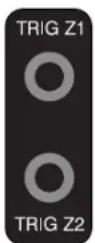
The Processor/Receiver has two rear-panel 12 volt trigger outputs that can be used to trigger such things as external power amplifier turn-on, projector power on, and screen automation. Each external device must have 12 volt triggering capability for this to work. The jacks are 3.5 mm mono with "Tip" being the 12 volt trigger output and "Sleeve" being ground. Each jack is capable of outputting a 12 volt, 70 mA switching signal. This not to be used for any other purpose such as jump starting the old car on a frosty morning.
Setup Menus
This section of the manual discusses how to navigate the set-up menus of the Processor/Receiver. X/XR Series Processors and Receivers are incredibly flexible and sophisticated and can be “personalized” for use with your performance theater system. While the set-up menus incorporate a number of default settings that we determined will work well with many theater systems, you will want to take the time to go through each of these set-up screens and make the appropriate adjustments to the settings.
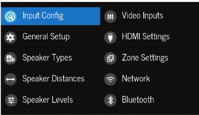
To get started in your set up, you can work directly from the front panel of the unit using the front panel buttons or the HTR-3 remote, or you can navigate to the set up options through a web browser by going to its IP address/setup [http://your IP address/setup/]. The web page menus follow the same format as the front panel menus noted below.
Front panel display: Main Menu
Navigating
Navigating the Set-Up Menus is a very simple process that can be done using the appropriate front panel controls on Processor/Receiver or by using the remote control.
- Press the Menu button once to enter the Setup Menus on the front panel. The main menu will show, from there you can select the parameters for configuration.
- Use the Input selection button "▲ Input +" and "▼ Input -" to navigate among the menus and use the "◀ Info" and "Mode ▶" buttons to select appropriate menu screen.
- Press the "SELECT" button or "OK" to select the menu options.
- Press the Menu button anytime to exit the Menu screens and any setting changes will be saved automatically.
Adjustment Highlight - Using your up/down keys on the remote or front panel, navigate this soothing blue bar to various options that you can adjust. This blue bar cursor will skip over items that are information only
Scroll Bars - These show the position of the displayed screen within longer menus. There are more options and information to see

Input Configuration
Each input has individual audio and video settings that can be adjusted specifically for its use.
Input - Identifies the currently selected source. Settings are displayed below.
Name - Specific name/label for this input that will show on the front display and the OSD. The name can be changed, and this is very useful when more than one source unit has similar functions (for example, two Satellite processors could be named SAT1 and SAT2).
Lip Sync - Many video processors and line multipliers cause a slight delay between the sound and the video picture. Highly compressed video signals such as MPEG encoded satellite processors and some DVDs also suffer from this problem. The Lip Sync setting delays the audio a small amount to allow the video image to catch up. If this is an audio only input - like Aux, then LipSync is grayed out.
Mode - Sets the initial audio decode mode for stereo sources on this input.
Last Mode - recalls the last used setting for stereo sources. See section "Surround Modes" on page 29 for more information.
MCH. Mode - Sets the initial audio decode mode for multi-channel digital sources on this input.
Last Mode - recalls the last used setting for multi-channel sources. See section "Surround Modes" on page 29 for more information.
Bass and Treble - Changes the bass and treble response for all speakers when using this input. Very useful when you have a source unit that has reduced frequency response due to the format (i.e. older VCRs or 8-Tracks)
Room EQ - When the Dirac Live application is run and EQ filters are Downloaded into one of the three slots available, this can be selected.
Not Calculated - (Information only) There are no EQ filters, so cannot be selected.
Project Name - Dirac Live Room EQ is applied to the current source and will display the name of the project from the Dirac Live application.
Off- Dirac Live Room EQ is not applied to the current source.
Input Trim - Selects the maximum analog signal for this input before clipping. This setting should match the audio output of your source units with the available settings being 1, 2, and 4 volts RMS and the default being 2 volts. Source units with low output levels can benefit from being set to higher output settings such as 1 V or 2 V.
Dolby Audio Processing - Applies Dolby Audio Processing to the incoming audio.
Off (default) - Dolby Audio Processing is not applied to this input.
Movie - Suitable for movie viewing.
Music - Suitable for music listening.
Night - Compresses the audio to be more suitable for latenight viewing or listening.
Stereo Mode - If you are using an external subwoofer, and are listening to stereo (two channel) sources, either digital or analog, you can select to configure how the subwoofer receives its bass information.
As Speaker Types - Your normal speaker configuration (as selected in the Speaker Types menu) determines your subwoofer output.
Left/Right - Full frequency audio will be sent to your front left and right speakers with no information going to the subwoofer.
Left/Right+Sub - Full frequency audio will be sent to your front left and right speakers plus bass information is directed to your subwoofer effectively duplicating the lower frequencies.
Sat+Sub - This setting will drive the frequencies defined in your Speaker Types crossover selections to the Sat for higher frequencies and 'Sub' for the lower frequencies.
Note: Stereo Mode is not available when using an analog source and you have selected the Stereo Direct mode.
Sub Stereo - If you have selected the "Left/Right+Sub" or "Sat+Sub" setting in the Stereo Mode menu, then this setting adjusts the level of the subwoofer when you are using a two-channel source.
IMAX Mode - Specifies if IMAX mode is enabled on the incoming audio stream (AUTO) or if forced to ON or OFF.
Auro-matic 3D - Specifies the mode of the Auro-matic 3D upconverter.
Auro-matic 3D Stength - Adjusts the amount of unprocessed to processed signal when using the Auro-Matic 3D upmixer.
Audio Source - Allows you to select how the Processor/Receiver receives audio signals for this source. Settings options are "HDMI," "Digital," or "Analog."
CD Direct - Use with PCM audio - this selection bypasses the compressed audio detection.
General Setup
General information and system controls.
Source Input - (Information only) Displays the currently active audio source input.
Incoming Format - (Information only) Displays format of digital audio stream if present.
Incoming Sample Rate - (Information only) Displays incoming sample rate of digital audio stream, if present.
Incoming Bitrate - (Information only) Displays bit rate of digital audio stream, if present.
Dialnorm - (Information only) When a Dolby Digital audio stream is connected to this input this is the Dialogue Normalization setting requested.
Incoming Video Format - Displays the incoming video resolution.
Audio Compression - Compressing the dynamic bandwidth of the audio can be a good thing, especially for those late night action movie festivals. Compression increases the volume of quiet sections and reduces the volume of the louder sounds. These 3 options for this setting only apply to some Dolby Digital or DTS soundtrack formats that support this function.
Off - (default) Audio compression is not applied (default)
Medium - For loud segments of the audio stream, compression is applied to reduce the level. Dolby True HD content will be compressed automatically
High - Maximum compression is applied with this setting. The differences between quiet passages and loud portions of the audio track are minimized
Balance - Adjusts the left/right balance of the front outputs.
DTS Dialog Control - Sets the level the for dialog channel in DTS audio streams.
Maximum Volume - Limits the highest volume that will play in the main zone. This is useful if you have speakers, amplifiers, or neighbors, with limited power handling abilities.
Max On Volume - This is the highest volume that the unit will play when it is first switched on. This prevents the unit from being turned on at shocking volume levels from the last time you were watching a good movie.
Display On Time - This sets the amount of time the display is lit after a command has been initiated. The default is always on.
Control - Enables or disables RS232 or IP (NET) control, a system that allows control from various third-party home automation systems. Note, only RS232 or IP control can be used, not both. Default setting is IP. The front panel and IR control are always active.
Power On - Determines how the Processor/Receiver powers on.
Standby - the unit is in Standby when powered on.
On - the unit is on and ready when powered on.
Last State - (default) the unit returns to the last On or Standby state before power was lost or the Main power switch was turned to off.
Language - The Front Display Setup Menu and OSD language can be selected from English, German, French, Spanish, Dutch, Russian, and Chinese.
Speaker Types
This series of menus allows you to select the types of speakers that you will be connecting to the Processor/Receiver.
"Large" speaker is one that is capable of reproducing a full range (20-20 kHz) audio signal. Use this setting when not using a subwoofer.
"Small" speaker is one that is not designed to reproduce deep bass frequencies and is generally used with a subwoofer (i.e. Satellite speakers typically can't play below 80 Hz). Please note that you can set High Pass crossovers independently for each speaker type when using the Small setting. For example, if you have your fronts set to Small 50 Hz and your sides and rear set to Small 80 Hz, frequencies below 50 Hz from the front channels as well as 80 Hz and below from the sides and rears will be sent to the subwoofer.
"Height 1, 2" selects the speaker types used for Dolby Atmos and DTS:X.
"None" If you do not have a speaker connected to an output (i.e. No Subwoofer or Back Speakers) then set that speaker size to "None".
"Subwoofer" Selects whether a subwoofer is present in your system.
"Channel 13 & 14" Selects whether Front subs or Wide speakers are present, options include Large, Small at various crossover frequencies.
"Channel 15 & 16" Selects between Rear Subs, Middle Heights or Center Height or none are present.
Height Type - Sets whether Dolby Enabled or ceiling mounted.
Using Channels 6 + 7 for - If your main speaker system has no Surround Back speakers, you can use the power from these unused amplifier channels to power Height 1 speakers, power speakers in Zone 2, or to biamp the front left and right speakers.
Filter slope - Sets the crossover filter slope. Options range from 12 dB to 48 dB
Sub gain - Sets output level trim for all specified subwoofers in 6 dB steps. Range is from 0 dB to -30 dB.
Speaker Distance
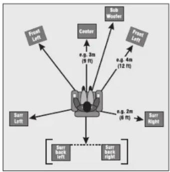
flowchart
graph TD
    A["Front Left"] --> B["Center"]
    C["Surr Left"] --> B
    D["Surr Back Left"] --> B
    E["Surr Back Right"] --> B
    F["Sub Wheeler"] --> B
    G["Front Left"] --> H["e.g. 3m (5 ft)"]
    I["Sub Wheeler"] --> J["e.g. 4m (12 ft)"]
    K["Surr Right"] --> L["e.g. 2m (6 ft)"]
The Speaker Distance settings help the sound from each speaker arrive at the listening seat at the same time. This provides a much more believable and immersive sound environment. Accurately measure the distance from the center of each speaker to the seated ear position of the main listening seat. Write each of these distances down (select Imperial or Metric) and enter them into the Processor/Receiver using this menu. Speakers not present (as you entered in the Speaker Types menu) will be greyed out. If the Dirac Live application has been used, the speaker distances can still be entered and edited in this menu.
Speaker Levels
It is critical to properly match the levels from each speaker to achieve a correct sound stage. The realism is totally lost if the footprints of a person walking across the screen change in volume as they move from left to center to right. We strongly recommend using a audio analyzer such as the AudioControl SA-4100i for this calibration. The levels are nearly impossible to judge by ear alone. Though not as accurate as using the SA-4100i, you can use a sound level meter for this adjustment.
With the internal test noise generator of the Processor/Receiver, adjust each speaker for a sound pressure level (SPL) of 75 dB using a "slow" response time on the SPL meter, placed at the main listening position at ear height.
You can use an External Test Tone from the currently selected HDMI input if you prefer.
Video Inputs
If desired, you can assign a video source to each of the "audio only" inputs. The default for each of these settings is "None". This is a great way to listen to the ball game over the Internet Radio and watch it over your normal video display device, though timing might be a little off.
HDMI Settings
X/XR Series Processors and Receivers feature very powerful video processing. Video settings should be selected carefully to optimize your video performance.
Zone 1 OSD - This selects the pop-up text messages to be On or Off.
When On, any adjustments made on the unit (like volume, mute state changes, sub trim level) will be shown on your display screen, as well as on the unit's front panel display.
When Off, any adjustments will only be shown in the unit's front panel display. This leaves your screen clear from interruption.
Zone 1 Out - Set the output for Zone 1 from either Output 1 (Main), Output 2 (Alt), or both.
Lipsync (Information Only) - When this feature is supported by the display device, this setting displays how much lip sync is applied to HDMI Outputs.
HDMI Audio to TV - Use this to set audio to be sent to the TV.
HDMI Bypass & IP - Sets the state of IP control and HDMI bypass of the unit while in Standby. When in Low Power mode, network or IP control and HDMI bypass are disabled. With HDMI & IP On, the unit will respond to IP control when in standby and HDMI bypass is enabled.
HDMI Bypass Source - Specifies the source used when HDMI bypass is on. Specific inputs can be specified or the last input used.
CEC Control - Enables/disables CEC control.
eARC Control - Enables/disables automatic volume control from the display.
TV Audio - Enables/disables auto-switching to eARC audio from the display.
Power Off Control - Enables/disables automatic power control from other CEC devices.
Zone Settings
This menu allows you select the audio and video control and volume settings for Zone 2.
Zone 2 Input - Selects the analog audio and video to be used for Zone 2.
Zone 2 Status - Selects if Zone 2 is in Standby or On.
Zone 2 Volume - Displays current volume level in Zone 2.
Zone 2 Max Vol - Selects the maximum volume setting for Zone 2.
Zone 2 Fixed Vol - Allows Zone 2 volume to be fixed at the current volume level. Volume can then be controlled with an external amplifier.
Zone 2 Max On Vol - Selects the maximum volume level for Zone 2 when the Processor/Receiver is powered on or comes out of stand-by mode.
Decoding Modes
For more detailed information on the various Dolby and DTS surround formats you can visit: www.dolby.com, or www.dts.com.
Specific decode and downmix/upmix options are available for Stereo and Multi-channel applications. The options for each format are accessible by touching the Mode button.
Two-channel source modes - The following decoding and surround modes are for creating multi-channel stereo modes from 2-channel sources. They are available on the Processor/Receiver for standard and high definition Dolby Digital 2.0, DTS 2.0, PCM or analog sources:
Stereo
DTS
Neural:X
Stereo Direct (analog sources) Auro 2D Surround
16 Channel Stereo Auro-matic 3D
Dolby
Surround
Auro
Native
Dolby Virtual Height
Multi-channel source modes - The following formats are available for multi-channel digital sources such as any Dolby, DTS or PCM multi-channel digital stream:
Native Auro 2D Surround
Stereo Downmix Auro-matic 3D
Dolby Virtual Height Auro Native
Upmixer
Network Settings
The Processor/Receiver has the ability of playing Internet radio stations as well as music stored on a network storage device like a PC or USB flash drive. Its default connection is wired and is set for DHCP - to automatically pick up an IP address if there is a DHCP server on the network.
The Dirac Live room correction system requires the Processor/Receiver to be connected to your network and with control set to IP.
Typically the computer network may use DHCP to automatically make the necessary network settings although the Processor/Receiver can also be configured manually when using a static IP address.
To set up a static IP or other manual entry IP address details, you will need to navigate to the unit's IP address (go to Menu>Network to find it) then type that IP address into a browser, then click on Network Settings for manual configuration.
SSID (Information Only) - Shows the network connection type
IP Address (Information Only) - Shows the unit's IP address
MAC Address (Information Only) - Displays the unique network card address of the Processor/Receiver
Friendly Name (Information Only) - Shows the name you've assigned to the Processor/Receiver
Bluetooth Settings
In this menu, Bluetooth pairing and device management are done.
Pair Device - Makes the Processor/Receiver discoverable by Bluetooth devices
Clear Paired Device List - This will clear the paired devices in the Processor/Receiver
Paired Devices - Paired devices are noted in this list
Playing Audio Files via Network Audio or USB
The network audio client on the Processor/Receiver is capable of supporting the following file formats:
-MP3
– WMA (Windows Media Audio)
- WAV
- FLAC (Free Lossless Audio CODEC)
- MPEG-4 AAC (iTunes with DRM10 support)
Navigate to the Processor/Receiver web page from your computer and select Web Client. From here you can select your USB as a source and control playback functions.
Playing music streaming services natively
Navigate to the Web Client to engage with streaming services directly. Open a browser and type in Processor/Receiver IP address/webclient. From this web client interface, you can set up your music streaming service, like Tidal or Qobuz, and select albums, artists and songs that the streaming service has made available.
Streaming
X/XR Series Processors and Receivers are Roon Ready, Airplay 2, and Google Chromecast built-in enabled. Being Roon Ready means that X/XR Series Processors and Receivers transparently discover and connect to Roon without any configuration, and bit-perfect audio is delivered from Roon to Processor/Receiver. With Airplay 2, you can stream to the Processor/Receiver via AirPlay2 from your favorite music app. Just tap on the AirPlay icon on your device and select the Processor/Receiver. For Chromecast streaming, first download Google Home from the Play store and set up the Processor/Receiver by following through the prompts. Once the Processor/Receiver is set up, you can stream directly to it from your favorite music streaming app. The Processor/Receiver will automatically switch over to the NET input when it receives a music stream.
Bluetooth
To stream from a Bluetooth source, such as your phone, pair your device to the Processor/Receiver via the web page or by selecting BT as the input from the front panel menu. Once paired and the Processor/Receiver is set to BT input, play back your favorite tracks.
Automation Integration
Please Note -
Automation documentation, modules and other control docs are available from the product pages on our website: audiocontrol.com
Part of the joy of a great home theater is that you don't have a tray of remote controls staring at you whenever you want to watch a movie. Hidden away behind the scenes is a workhorse that takes care of the mundane tasks of turning on all the components, lowering the curtains, dimming the lights, popping the corn, etc. This faithful servant can take the form of a simple learning remote control, or a system as capable as a whole house automation system with touch screens. There are a wide variety of theater controllers available.
There are 2 methods of controlling the Processor/Receiver, other than through the IR remote and the Front Panel. You may choose either RS232 or IP control via the General Settings menu. Both methods use the same command structure format as defined in the automation documentation found on our website. The command set also takes advantage of the extensive discrete IR command library with the IR simulation command. This adds a great deal of flexibility to system design, general functionality and personal customization. It is possible to use both hand held remotes and control panels in the same installation depending on your needs.
IP Control
Obtain the IP address from the Processor/Receiver's Network menu. Setting the IP address of the unit to static is good practice. When setting to a static address, always include the DNS and subnet info otherwise your Internet Radio will not likely work. Communication occurs on port 50,000 in the automation system. You will need to confirm that control is set to IP – this is set at the bottom of the General Settings menu.
Example: 192.168.20.246:50000
RS232 Serial Control
You must set the external RS232 control system serial port of your control system to match the data communication speed and format of the Processor/Receiver. If these settings are incorrect, the Processor/Receiver will not respond to the commands.
Communication parameters:
Baud Rate: 38,400
Start Bit: 1
Data Bits: 8
Stop Bit: 1
Parity: None
Flow Control: None
Cable Wiring
The cable wiring to connect the Processor/Receiver to your control system will depend on the RS232 output connection on the controller. Make certain that you wire the Transmit Data output on the serial controller to the Receive Data on the Processor/Receiver and vice versa on the Receive Data line on the controller system. Connect the signal grounds on the control system and the Processor/Receiver series together. The RS232 connection on the Processor/Receiver is a DB-9 Male connector, labeled Control and is wired as follows:
Pin 2 Receive Data (RXD)
Pin 3 Transmit Data (TXD)
Pin 5 Ground
To connect the Processor/Receiver to a standard PC serial COM port; wire the cable in a 'null modem' arrangement using the appropriate serial cable.
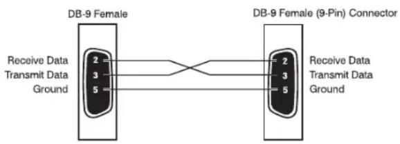
flowchart
graph LR
    A["DB-9 Female"] -->|2| B["DB-9 Female (9-Pin) Connector"]
    A -->|3| B
    A -->|5| B
    B -->|2| A
    B -->|3| A
    B -->|5| A
    A -->|Receive Data Transmit Data Ground| B
Command Structure - Issuing
The RS232 serial control structure of the Processor/Receiver is a string of hexadecimal values with a minimum of six bytes. When issuing a command, the structure of the string is as follows: Start Transmission, Zone Number, Command Code, Data Length, Data and End Transmission. We will use an abbreviated form for easy reference in the following format:
Parameter
Command
Description
START 0x21 Begin transmission
ZONE NUMBER 0x01 Zone 1
0x02 Zone 2
COMMAND CODE See code list The code of the
command
DATA LENGTH 0x01, 0x02 etc... Number of data parameters to follow
DATA
See code index
The parameters for the
command
ETR
0x0D
End transmission
As an example:
To change the video source (only video, not audio) in Zone 1 to SAT:
0x21 0x01 0x0A 0x01 0x01 0x0D
To change the source (both audio and video), the command is the 0x08 – IR simulation command. See page 36 for more info.
Command Structure - Receiving
Command processing begins when the first 0x0D (carriage return) is received. The Processor/Receiver will respond, either by making the change specified with a status update answer code or by replying with an error answer code, within 3 seconds. More commands, however, may be sent before the Processor/Receiver responds to the first command. When a command is received, the Processor/Receiver echoes the command back in the following format:
Parameter Command Description
| START | 0x21 | Begin transmission |
ZONE NUMBER 0x01 Zone 1
0x02 Zone 2
COMMAND CODE See code list The code of the command
| ANSWER CODE | 0x00 | No problems – statusupdated | |
| 0x82 | Incorrect | Zone | |
| 0x83 | Incorrect | Command | |
| 0x84 | Incorrect Parameter | ||
| 0x85 | Invalid Command incurrent state | ||
0x86 Data length is incorrect
DATA LENGTH 0x01, 0x02 etc... Number of data units to follow
DATA See code list The parameters for the response, limited to 255
ETR 0x0D End transmission
As an example:
Answer code for source change in Zone 1 to DVD: 0x21 0x01 0x0A 0x00 0x01 0x00 0x0D
Simulating the RC-5 IR command via RS232
A key feature in the Processor/Receiver is the ability to simulate RC5 format IR commands via serial commands. The IR simulation command will contain 7 bytes as there will be 2 bytes for the RC-5 command. The actual command
Changes in state from different inputs
While the Processor/Receiver is controlled by a serial command, its state may be changed by other inputs such as the front panel or through IR. Such changes in state will yield a response with an answer code from the Processor/Receiver. In order to determine the command code, you may use the response to get the code for the desired function if you can't find the listing for it in the automation table.
Serial and IR Code Tables
Please head on over to our web site, www.audiocontrol.com, to get the serial/IP protocol doc. You can find a complete listing of the automation protocol – commands, cheats, rich detail that makes most eyes glaze over – at the product pages. You can also find control modules/drivers/profiles on the products pages as well. Alternatively, if you can't sleep, and are unfamiliar with hex, read the doc – it'll put you right to sleep.
Dirac Live speaker setup system
For a more detailed Dirac Live setup walkthrough visit: audiocontrol.com/ dirac-setup/
...or scan:

X/XR Series Processor and Receivers have an automatic speaker setup system called Dirac Live with Dirac Live Bass Control, from Dirac Research. The supplied microphone is used with your computer on the same network to measure the sound output of the system. Dirac Live automatically calibrates the settings of all the speakers in the system, and will apply the optimized EQ settings to the main room. From the measurements, Dirac Live computes the distance, level, and identifies any problems that can be corrected or reduced by room EQ settings.
The procedure for running all this wonderful technology, is as follows:
- Connect the supplied microphone to the USB port on your PC or MAC connected to the same network as the Processor/Receiver.
- Position the microphone so it is close to the normal/usual position of your head when you are sitting in your home theater. We suggest using a mic stand (a boom stand works best) to position mic. Point the microphone upwards and in a position where it has a direct line of sight view of all speakers.
- If your system uses an active subwoofer, set the output level controls to approximately match the front speakers.
- Run the Dirac Live application on your computer. A calibration test tone will run through all speakers in your system, a number of times as the different speaker responses are calculated. If some speakers are not used, there will be a silence when these are reached. Check the software application for the progress and information.
By default, Room EQ is not automatically applied to the source inputs. You can enable this using the Input Configuration display menu of the unit. Listen to the different sources and source material, and judge if the room EQ settings give an improvement.
During the measurements, try your best to create as quiet an environment as possible. This is not the time for little Timmy's circus animal birthday party.
While EQ settings can be beneficial, there is no substitute for getting things right in the first place, with regard to speaker placement, speaker type, and room treatments to avoid reflections etc.
Downloading Dirac Live with Dirac Live Bass Control
To download the Dirac Live PC/MAC application and quick start guide, please visit: dirac.com/live/downloads/
Troubleshooting Common Problems
General
There are no lights on the Processor/Receiver
√ Pressing any button on the front panel should wake the Processor/Receiver.
√ Verify that the power cord is plugged into a live AC outlet.
√ Verify that the front panel Power switch is "On".
The main front panel display is blank
√ Press the Display button. This button controls the display brightness and also allows you to turn the display off entirely.
The main zone changes while selecting sources from Zone 2
√ Change the Zone 1 Control option in the Zone 2 Configuration Menu to Off.
Video
No video/picture
√ Verify your video display or projector is turned on and set to the correct input for the Processor/Receiver. Press the Menu button on the Processor/Receiver and look for the Setup Menus to show on the video display.
√ Verify the correct input on the video display is selected for the output of the source.
√ Verify the Video Input assignment configurations. Make certain that the correct video input is assigned to the source you are playing.
No Video on Zone 2
√ Verify the HDMI input from the source is connected.
There is no On-Screen Display (OSD)
√ Verify the OSD is turned on in the Processor/Receiver configuration settings.
√ Verify that the correct input is selected on the video display or projector.
Audio
The audio doesn't match the video
√ The Video and Audio input can be selected independently in the Main Menu. Verify they are set the same.
√ Verify the correct Video Input and Digital Audio input assignments are configured for the Source Input.
The sound is poor or distorted
√ Verify the speaker settings configuration matches your speakers. If a speaker is set to Large and it cannot reproduce full range bass, you will hear distortion.
√ If the trouble is only on some channels: Verify the audio RCA cables to the power amplifiers are working and seated properly.
√ If the trouble is in all channels: Verify the Input Trim setting in the Advanced Configurations is not set too low.
Cannot select Dolby Digital or DTS decoding mode
√ The Processor/Receiver can only decode formats encoded onto the source. Normally these are marked on the packaging or liner notes of the material.
√ Verify that the correct format is selected in the Start Menu of the disc.
√ Verify that the digital input from the source is properly connected to the Processor/Receiver.
√ Verify that the digital output of the source is enabled. Some Blu-ray players have a setup menu that can only be accessed if there is no disc in the player.
Hum on analog inputs
√ Verify that all the two channel analog audio cables are connected properly.
√ If the hum only occurs on one source, try a different set of connecting cables.
√ If the hum occurs on a source with an external connection such as an antenna or cable TV, try disconnecting that input. If the hum disappears, put a ground isolator on that connection.
√ It does not know the words.
No audio on Zone 2
√ Zone 2 is muted when unit is first turned on.
√ Make sure you are using a source with analog outputs.
No Zone 2 audio when playing a DTS encoded video
√ Most Blu-ray players cannot output a stereo analog version of the soundtrack while playing a DTS encoded disk. If you want to watch the movie in the second zone, select the Dolby Digital soundtrack on the disk.
My boomerang won't come back
√ It's a stick.
Should your Processor/Receiver Need Service
Before returning any item to AudioControl, you must obtain a return authorization.
Tech Support contact and hours:
+1 (425) 775-8461
techsupport@audiocontrol.com
Monday - Friday 8 am -5 pm PDT
After obtaining a return authorization, please write your RA number on the outside of the shipping box and include the following items when returning the unit:
- A copy of your proof of purchase. No originals please. We cannot guarantee returning them to you.
- A brief explanation of the trouble you are having with the unit. (You'd be surprised how many people forget this.) If you can supply a really detailed description of the problem, this would be so much better, and our service technicians may add you to their Christmas Card list. Please include any notes about the system and other components you are using. Is it an intermittent problem that only occurs on the first full moon of Spring?
- A return street address. (No PO Boxes, please).
- A daytime phone number in case our technicians have a question about the problem you are having, or if they are just feeling lonely.
Package the unit in the original packaging if you still have it, and if the cat hasn't had three litters of kittens in the box. Use great care and plenty of good packing materials to protect the unit and prevent it from moving about inside the box. Do not use loose materials like packing peanuts or real peanuts.
You are responsible for the freight charges to us, but we'll pay the return freight back as long as the unit is under warranty. We match whatever shipping method you use to send it to us, so if you return the unit overnight freight, we send it back overnight. We recommend United Parcel Service (UPS) for most shipments.
Repair service is available at:
AudioControl Service Department
22410 70th Avenue West, Suite 1
Mountlake Terrace, WA 98043
USA
Warranty
...and now a word from the legal department...
People are scared of warranties. Lots of fine print. Months of waiting around. Well, fear no more. This warranty is designed to make you rave about us to your friends. It's a warranty that looks out for you and helps you resist the temptation to have your friend, who's "good with electronics", try to repair your AudioControl product. So go ahead, read this warranty, then take a few days to enjoy your new X/XR Series Processor/Receiver before logging onto the our web site at www.audiocontrol.com to register your purchases.
Our warranty has conditional conditions! "Conditional" doesn't mean anything ominous. The Federal Trade Commission tells all manufacturers to use the term to indicate that certain conditions have to be met before they'll honor the warranty. If you meet all of these conditions, we will warrant all materials and workmanship on the Processor/Receiver for five (5) years from the date you bought it, and we will fix or replace it, at our option, during that time. Here are the conditional conditions:
- You need to register your purchases with us by going to the AudioControl product registration page at www.audiocontrol.com/product-registration.
- You must keep your sales receipt for proof of purchase showing when and from whom the unit was bought. We're not the only ones who require this, so it's a good habit to get into with any major purchase.
- The Processor/Receiver must have originally been purchased from an authorized AudioControl dealer. You do not have to be the original owner, but you do need a copy of the original sales receipt or invoice.
- You cannot let anybody who isn't: (A) the AudioControl factory; (B) somebody authorized in writing by AudioControl to service the Processor/Receiver. If anyone other than (A) or (B) messes with the Processor/Receiver, that voids your warranty.
- The warranty is also void if the serial number is altered or removed, or if the Processor/Receiver has been used improperly. Now that sounds like a big loophole, but here is all we mean by it:
Unwarranted abuse is: (A) physical damage (don't use the Processor/Receiver to level your projection TV); (B) improper connections (120 volts into the RCA jacks can fry the poor thing); (C) sadistic things. This is the best product we know how to build, but if you strap it to the front bumper of your Range Rover, something will break.
Assuming you conform to 1 through 5 (and it really isn't all that hard to do) we get the option of fixing your original unit or replacing it with a new one.
Legalese Section
This is the only warranty given by AudioControl. This warranty gives you specific legal rights, and you may also have rights that vary from state to state. Promises of how well the unit will work are not implied by this warranty. Other than what we've said we'll do in this warranty, we have no obligation, express or implied. We make no warranty of merchantability or fitness for any particular purpose. Also neither we nor anyone else who has been involved in the development or manufacture of the unit will have any liability of any incidental, consequential, special or punitive damages, including but not limited to any lost profits or damage to other parts of your system by hooking up to the unit (whether the claim is one for breach of warranty, negligence of other tort, or any other kind of claim). Some states do not allow limitations of consequential damages. Failure to register your product negates any service claims. The warranty included with the unit shall supersede this plain-text version if there is any inconsistency between the two.
Maestro X9S / Maestro X9 Specifications
Inputs
Analog Audio Inputs - Unbalanced 6 Stereo Pairs
Analog Audio Inputs - Balanced 2 Stereo Pair
Nominal Audio Input sensitivity 1V-4V
Input Impedance 47 kOhm
Signal to Noise Ratio ....>102 dB
Digital Audio Inputs 6
Video inputs 7 HDMI 2.1 (X9S)
7 HDMI 2.0b (X9)
Outputs
Total Harmonic Distortion -100 dB
Frequency Response 20 Hz - 20 kHz
Preamp Balanced Audio Outputs 7 main channels, 1 subwoofer
4 height channels
4 configurable channels
Preamp Unbalanced Audio Outputs 7 main channels, 2 subwoofer
4 height channels, Zone 2
4 configurable channels
Main Video Outputs .... Dual (2) HDMI
Second Zone Output 1 HDMI, Stereo analog audio
Control
12 Volt Trigger Outputs .... Main Zone, Zone 2
RS-232 Serial control 1 DB-9
IR Receiver Inputs .... Main Zone, Zone 2
General
Power Consumption (Stand By) .... Less than 0.5 Watts
Power Consumption (typical usage) 90 Watts
Power Consumption (maximum) 100 Watts
Dimensions (including terminals and feet) 17"W x 16.9"D x 7.3"H
Weight 27.1 lbs.
All specifications are subject to change.
Maestro X7S / X7 Specifications
Inputs
Analog Audio Inputs - Unbalanced 6 Stereo Pairs
Analog Audio Inputs - Balanced....2 Stereo Pair
Nominal Audio Input sensitivity 1V-4V
Input Impedance 47 kOhm
Signal to Noise Ratio ....>100 dB
Digital Audio Inputs 6
Video inputs 7 HDMI 2.1 (X7S)
7 HDMI 2.0b (X7)
Outputs
Total Harmonic Distortion -100 dB
Frequency Response 20 Hz – 20 kHz
Preamp Balanced Audio Outputs 7 main channels, 1 subwoofer
4 height channels
4 configurable channels
Preamp Unbalanced Audio Outputs ....7 main channels, 2 subwoofer
4 height channels, Zone 2
4 configurable channels
Main Video Outputs .... Dual (2) HDMI
Second Zone Output ....1 HDMI, Stereo analog audio
Control
12 Volt Trigger Outputs .... Main Zone, Zone 2
RS-232 Serial control 1 DB-9
IR Receiver Inputs .......Main Zone, Zone 2
General
Power Consumption (Stand By) .... Less than 0.5 Watts
Power Consumption (typical usage) 90 Watts
Power Consumption (maximum) 100 Watts
Dimensions (including terminals and feet) 17"W x 16.9"D x 7.3"H
Weight 27.1 lbs.
All specifications are subject to change.
Concert XR-8S / XR-8 Specifications
Inputs
Analog Audio Inputs....6 Stereo Pairs
Nominal Audio Input sensitivity 1V-4V
Input Impedance 47 kOhm
Signal to Noise Ratio 100 dB
Digital Audio Inputs 6
Video inputs 7 HDMI 2.1 (XR-8S)
7 HDMI 2.0b (XR-8)
Outputs
Speaker Level Channels 7
Power Output .... 120 Watts per ch into 8 ohms .... 200 Watts per ch into 4 ohms
Minimum Speaker Load 4 ohms
Total Harmonic Distortion -100 dB
Frequency Response 20 Hz - 20 kHz
Preamp Audio Outputs .... 7 main channels, 2 subwoofer .... 4 height channels, Zone 2 .... 4 configurable channels
Main Video Outputs ....Dual (2) HDMI
Second Zone Output ....1 HDMI, Stereo analog audio
Control
12 Volt Trigger Outputs .......Main Zone, Zone 2
RS-232 Serial control 1 DB-9
IR Receiver Inputs .... Main Zone, Zone 2
General
Power Consumption (Stand By) .... Less than 0.5 Watts
Power Consumption (typical usage) 100 Watts
Power Consumption (maximum) 1500 Watts
Dimensions (including terminals and feet) 17"W x 17.5"D x 7.3"H
Weight 40.3 lbs
All specifications are subject to change.
Concert XR-6S / Concert XR-6 Specifications
Inputs
Analog Audio Inputs....6 Stereo Pairs
Nominal Audio Input sensitivity ....1V-4V
Input Impedance 47 kOhm
Signal to Noise Ratio 100 dB
Digital Audio Inputs 6
Video inputs 7 HDMI 2.1 (XR-6S)
7 HDMI 2.0b (XR-6)
Outputs
Speaker Level Channels 7
Power Output 100 Watts per ch into 8 ohms
Minimum Speaker Load ....4 ohms
Total Harmonic Distortion -100 dB
Frequency Response 20 Hz – 20 kHz
Preamp Audio Outputs .... 7 main channels, 2 subwoofer
2 height channels, Zone 2
4 configurable channels
Main Video Outputs .... Dual (2) HDMI
Second Zone Output ....1 HDMI, Stereo analog audio
Control
12 Volt Trigger Outputs ....Main Zone, Zone 2
RS-232 Serial control 1 DB-9
IR Receiver Inputs ....Main Zone, Zone 2
General
Power Consumption (Stand By) .... Less than 0.5 Watts
Power Consumption (typical usage) 100 Watts
Power Consumption (maximum) 1500 Watts
Dimensions (including terminals and feet) 17"W x 17.5"D x 7.3"H
Weight 40.3 lbs
All specifications are subject to change.
Concert XR-4 Specifications
Inputs
Analog Audio Inputs....6 Stereo Pairs
Nominal Audio Input sensitivity 1V-4V
Input Impedance 47 kOhm
Signal to Noise Ratio 100 dB
Digital Audio Inputs 6
Video inputs 7 HDMI 2.0B
Outputs
Speaker Level Channels 7
Power Output 65 Watts per ch into 8 ohms
Minimum Speaker Load 4 ohms
Total Harmonic Distortion -100 dB
Frequency Response 20 Hz - 20 kHz
Preamp Audio Outputs .... 7 main channels, 2 subwoofer .... 4 height channels
Main Video Outputs ....Dual (2) HDMI
Control
12 Volt Trigger Outputs .... Main Zone
RS-232 Serial control 1 DB-9
IR Receiver Inputs .... Main Zone
General
Power Consumption (Stand By) .... Less than 0.5 Watts
Power Consumption (typical usage) 90 Watts
Power Consumption (maximum) 1500 Watts
Dimensions (including terminals and feet) 17"W x 17.5"D x 7.3"H
Weight 40.3 lbs
All specifications are subject to change.
Appendix A: Feet Removal Procedure
Note: If this was your real appendix, please consult your health care professional as it should not look like this.
The feet of the unit can be removed to create a cleaner look when fitting the unit into a rack.
You must make sure that the ventilation slots in the bottom panel are not covered and that cooling air flow is not restricted.
Tools Required
- A medium-sized flat-bladed screwdriver, 1/4" wide or narrower.
- Needle-nosed pliers
The Procedure
-
Make sure that the power cord and all other cords are disconnected from the unit.
-
Carefully place the unit upside-down on a flat surface, such as the kitchen table with a clean and dry towel on it.
-
Remove the adhesive non-slip grips from the bottom of each foot.
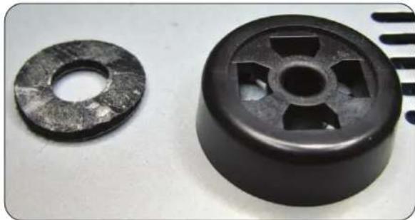
natural_image
Two black mechanical components: a circular washer and a circular impeller with cutouts (no text or symbols visible)- Identify the four locking tabs securing the foot to the chassis. The photo of a removed foot shows the details of the locking tabs.
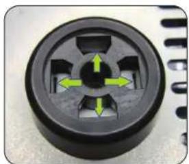
natural_image
Close-up of a black circular mechanical component with green directional arrows indicating ports or features (no text or symbols visible)
natural_image
Close-up of a metallic mechanical component with radial slots and central hub (no visible text or symbols)-
Use the small flat-bladed screwdriver to gently pry the four locking tabs outward to release the foot from the chassis. Use the needle-nose pliers to pull upward at the same time, with (to get all technical for a moment) a bit of a jiggle-joggle motion.
-
Repeat for all 4 feet. Place all the feet in your sock drawer in case you wish to reinstall them in the future.
natural_image
Close-up of a black mechanical component with a pointed tip, showing internal slots and a central hole (no text or symbols visible)
natural_image
Close-up of a hand using a screwdriver to adjust a mechanical component with a circular wash, no visible text or symbols.Appendix B:
This appendix was removed as it became bloated and painful.
AudioControl®
Making Good Sound Great™
22410 70th Avenue West
Mountlake Terrace, WA 98043 USA
+1 (425) 775-8461
www.audiocontrol.com
- Immersive AV Processors & Receivers Installation Manual
- Important Safety Instructions
- CAUTION AVIS
- A GUIDED TOUR
- SETUP AND CONFIGURATION
- CONNECTION TIPS
- NAVIGATING THE SETUP MENUS
- Greetings from the rainforest
- Key Features
- HDMI 2.1 and HDCP 2.3 SUPPORT
- HDMI 2.0b and HDCP 2.2 SUPPORT
- eARC - ENHANCED AUDIO RETURN CHANNEL
- BEST IN CLASS AUDIO PROCESSING AND CONVERSION
- IMAX ENHANCED
- DOLBY VISION
- ANALOG PREAMPLIFIER OUTPUTS
- NETWORKED AUDIO STREAMING
- EXTENSIVE AUTOMATION INTEGRATION
- AWARD WINING QUALITY
- Front Panel Features
- Rear Panel Features
- VOLTAGE SELECTION - The
- FAN - A fan is used to cool down the internal power amplifiers in your
- HTR-3 Remote Control
- Remote Features
- Other useful items
- General Functions
- Buttons/Functions in the Amp Device Mode
- Set-up and Configuration
- Unit Placement
- Speaker Considerations and Placement
- Front LCR (Left, Center, Right) Speakers
- Wide Presence Speakers
- Side Surround Speakers
- Rear (Back) Surround Speakers
- Subwoofer(s)
- Height Speakers
- Channels 13-16
- Channels 13 & 14: Channel 15 & 16:
- Power Wiring
- Audio Connections
- Video Connections
- eARC (Audio Return Channel)
- IR (Infrared) Remote Control Connections
- 12V Trigger Connections
- Setup Menus
- Navigating
- Input Configuration
- General Setup
- Speaker Types
- Speaker Levels
- Video Inputs
- HDMI Settings
- Zone Settings
- Decoding Modes
- Network Settings
- Bluetooth Settings
- Playing Audio Files via Network Audio or USB
- Playing music streaming services natively
- Streaming
- Bluetooth
- Automation Integration
- Please Note -
- IP Control
- RS232 Serial Control
- Communication parameters:
- Cable Wiring
- Command Structure - Issuing
- Parameter
- Command
- Description
- Command Structure - Receiving
- Simulating the RC-5 IR command via RS232
- Changes in state from different inputs
- Serial and IR Code Tables
- Dirac Live speaker setup system
- Downloading Dirac Live with Dirac Live Bass Control
- Troubleshooting Common Problems
- General
- There are no lights on the Processor/Receiver
- The main front panel display is blank
- The main zone changes while selecting sources from Zone 2
- Video
- No video/picture
- No Video on Zone 2
- There is no On-Screen Display (OSD)
- Audio
- The audio doesn't match the video
- The sound is poor or distorted
- Cannot select Dolby Digital or DTS decoding mode
- Hum on analog inputs
- No audio on Zone 2
- No Zone 2 audio when playing a DTS encoded video
- My boomerang won't come back
- Should your Processor/Receiver Need Service
- Tech Support contact and hours:
- Repair service is available at:
- Warranty
- Legalese Section
- Maestro X9S / Maestro X9 Specifications
- Inputs
- Outputs
- Control
- Maestro X7S / X7 Specifications
- Concert XR-8S / XR-8 Specifications
- Concert XR-6S / Concert XR-6 Specifications
- Concert XR-4 Specifications
- Appendix A: Feet Removal Procedure
- Tools Required
- The Procedure
- Appendix B:
- AudioControl®
Brand : AudioControl
Model : Maestro X7S
Category : Audio Electronics