NSD-35 - Uncategorized Vello - Free user manual and instructions
Find the device manual for free NSD-35 Vello in PDF.


| Product Type | Wired Remote Shutter Release |
| Brand | Vello |
| Model | NSD-35 |
| Compatibility | Nikon cameras with 10-pin remote terminal (e.g., D300, D700, D800, D3, D4) |
| Cable Length | 3 ft (0.9 m) |
| Dimensions (control unit) | 2.5 x 1.5 x 0.8 in (6.4 x 3.8 x 2.0 cm) |
| Weight | 1.2 oz (34 g) |
| Power Source | No battery required; powered by camera via 10-pin port |
| Shutter Release Button | Half-press for autofocus, full press for shutter release |
| Lock Function | Sliding lock for bulb/long exposures |
| Operating Temperature | 14°F to 104°F (-10°C to 40°C) |
| Construction Material | Plastic control unit with rubberized coating, PVC cable |
| Indicator Light | None |
| Warranty | 1-year limited |
| Included Accessories | Remote unit, instruction manual |
| Maintenance | Wipe with dry cloth; avoid liquids and excessive heat |
| Safety | Not intended for underwater use; keep away from children |
| Repairability | Not user-serviceable; contact Vello support for issues |
| Country of Origin | China |
Frequently Asked Questions - NSD-35 Vello
User questions about NSD-35 Vello
0 question about this device. Answer the ones you know or ask your own.
Ask a new question about this device
Download the instructions for your Uncategorized in PDF format for free! Find your manual NSD-35 - Vello and take your electronic device back in hand. On this page are published all the documents necessary for the use of your device. NSD-35 by Vello.
USER MANUAL NSD-35 Vello
natural_image
Black and white photo of a digital camera with a screen displaying a colorful landscape (no visible text or symbols)
VELLO
THANK YOU FOR CHOOSING VELLO
The Vello NSD-35 makes it easy to digitize 35mm negative film strips and mounted slides with a camera and macro lens. This kit features an LED light source that provides bright and consistent light, allowing you to accurately capture the film and slides. Included are lens adapters and extension tubes that make it easy to use a variety of macro lenses and adjust for the correct focus distance. Process the images with your favorite photo editing software or with cameras that have a negative digitization mode.
PRECAUTIONS
- Please read and follow all the instructions in this manual.
- Do not disassemble or perform any unauthorized modifications. Use only with the compatible devices specified in this manual.
- Keep this device away from water and extreme humidity, and store it in a cool and dry place.
-
Do not operate in conditions with extreme heat or cold.
-
Do not operate in the presence of flammable gases or vapors.
- Keep out of reach of children. This device contains small parts which may pose a choking hazard.
- All images are for illustrative purposes only.
OVERVIEW
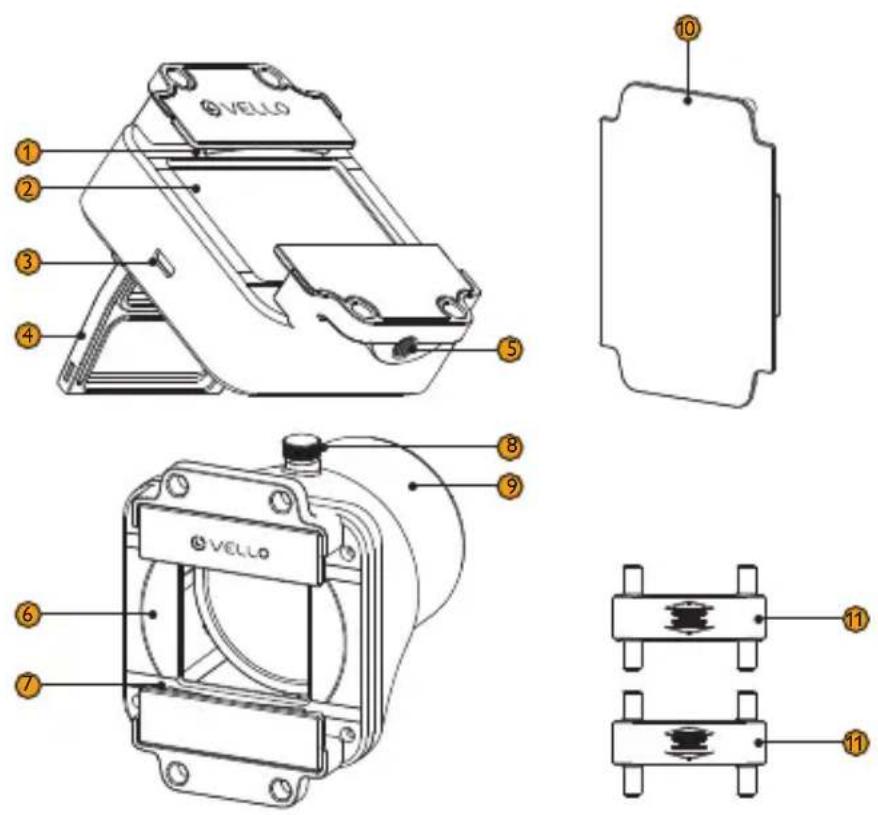
- Holder clips
- LED light
- USB Micro-B port
- Stand
- 1/4-20 mount
- Film/Slide carrier
- Holder clips
- Locking screw
- Carrier extension 1
- Diffuser
- Connectors (×2)
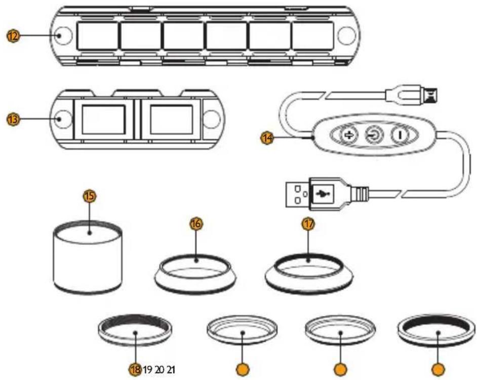
- Film strip holder
- Mounted slide holder
- USB Type-A to Micro-B power control cable
- Extension tube 2 (×2)
- Lens adapter 3
- Lens adapter 4
- Lens adapter 5
- Lens adapter 6
- Lens adapter 7
- Lens adapter 8
ASSEMBLING THE DIGITIZER
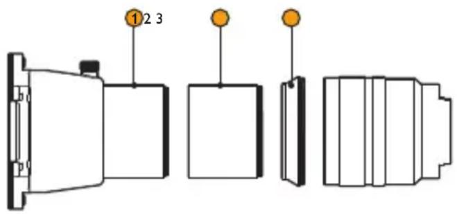
To assemble the digitizer, you'll need to select the right adapters, so the film or slide is positioned at your lens's minimum focus distance. Table 2 (page 12) shows a variety of popular macro lenses and their respective adapter combinations. If your lens is not listed in the table, replicate its minimum focus distance by adding the values of the carrier extension (1), extension tube (2), and lens adapter (3–8).
Example:
① Carrier extension (1)
② extension tube(s) (2)
③ lens adapter (3-8)
= lens minimum focus distance.
- Use table 2 below as a guide to select the right adapters for your lens. Make sure to remove all hoods, filters, and other lens attachments before assembling the digitizer.
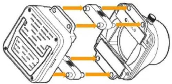
- Attach the two connectors and the LED light to the end of the carrier.
natural_image
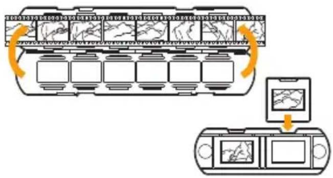
Technical diagram of a mechanical assembly with orange arrows indicating directional flow (no text or labels)- Insert your 35mm film strip or mounted slide into the appropriate holder. To avoid damage, be sure the film is correctly placed in the holder when closing.
flowchart
graph TD
    A["Control Panel"] --> B["Sensor Icon 1-10"]
    B --> C["Display Panel 1-10"]
    C --> D["Sensor Icon 1-14"]
    D --> E["Display Panel 1-14"]
    E --> F["Sensor Icon 1-15"]
    F --> G["Display Panel 1-15"]
    G --> H["Sensor Icon 1-16"]
    H --> I["Display Panel 1-16"]
    I --> J["Sensor Icon 1-17"]
    J --> K["Display Panel 1-17"]
    K --> L["Sensor Icon 1-18"]
    L --> M["Display Panel 1-18"]
    M --> N["Sensor Icon 1-19"]
    N --> O["Display Panel 1-19"]
    O --> P["Sensor Icon 1-20"]
    P --> Q["Display Panel 2-20"]
    Q --> R["Sensor Icon 2-21"]
    R --> S["Display Panel 2-21"]
    S --> T["Sensor Icon 2-22"]
    T --> U["Display Panel 2-22"]
    U --> V["Sensor Icon 2-23"]
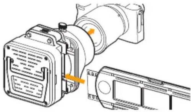
- Attach the digitizer to your lens using the appropriate lens adapter (see table 1). Insert the holder into the carrier's holder clips. Look through the camera's viewfinder or at its LCD screen to make sure you have the proper alignment. To fine-tune your frame, loosen the locking knob and rotate the carrier to adjust tilt.
natural_image
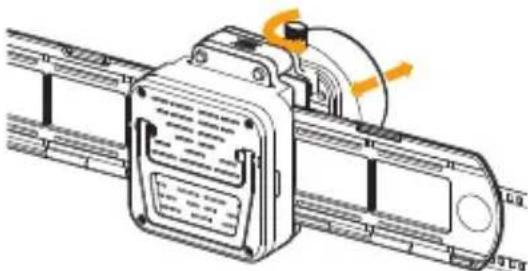
Technical line drawing of a mechanical assembly with no visible text or symbols- Focus the image, starting with your lens set to manual focus, and to its minimum focus distance. You may need to consult your lens's manual. To fine-tune the focus distance, loosen the locking knob and slide the carrier in and out. The focal plane needs to meet the lens's minimum focus distance for you to get a sharp image.
Note: It is recommended that you disable image stabilization.
natural_image
Technical line drawing of a mechanical device with rollers and conveyor belt (no text or symbols)-
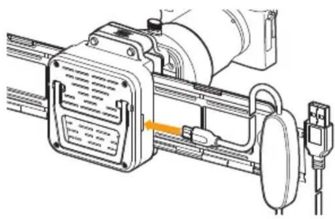
Connect the LED light to a USB power source (not included) via the USB power control cable.
-
Press the power button to turn on the LED light. Press the + or - buttons to increase or decrease the LED's brightness.
Warning! To avoid damage, do not leave the film in the NSD-35 with the light on for an extended period.
natural_image
Technical line drawing of a mechanical device with attached components (no text or symbols)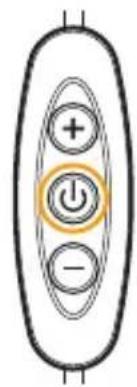
STAND-ALONE USE
LED Light
Use the LED light as a stand-alone image viewer with the built-in stand or the 1/4-20 mount.
Carrier
Attach the diffuser to the carrier, and use a separate light source for digitizing the film or slides.
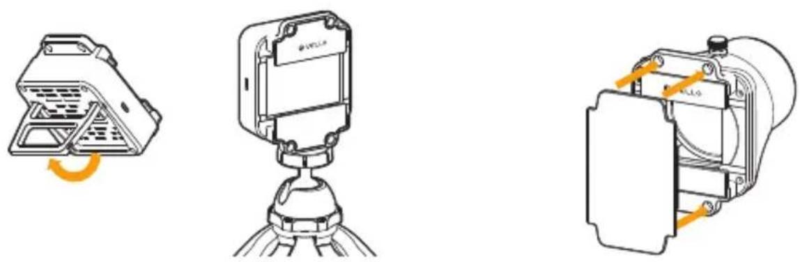
Table 1. Carrier extension, lens adapter, and extension tube diameters
| Part Diameters | ||
| Lens Adapter and Extension Tube Diameters | Extension Tube 2 52-52mm | |
| Lens Adapter 3 62-52mm | ||
| Lens Adapter 4 67-52mm | ||
| Lens Adapter 5 55-52mm | ||
| Lens Adapter 6 46-52mm | ||
| Lens Adapter 7 49-52mm | ||
| Lens Adapter 8 58-52mm | ||
| Weight | accessories | |
Table 2. Compatible lenses
Note: if your lens is not listed here, see Assembling the Digitizer (page 6) for instructions on how to configure the adapter(s).
| Brand Compatible Lenses Configuration | ||
| Canon | EF-S 60mm f/2.8 USM 1 - 2 - 2 - Lens | |
| EF 100mm f/2.8L Macro IS USM 1 - 2 - 2 - 4 - Lens | ||
| EF 100mm f/2.8 Macro USM 1 - 2 - 2 - 8 - Lens | ||
| RF 100mm f/2.8L Macro IS USM 1 - 2 - 4 - Lens | ||
| Nikon | AF-S DX Micro NIKKOR 40mm f/2.8 G 1 - Lens | |
| NIKKOR Z MC 50mm f/2.8 Macro 1 - 3 - Lens | ||
| AF Micro-NIKKOR 60mm f/2.8D 1 - 3 - Lens | ||
| NIKKOR Z MC 105mm f/2.8 VR S Macro 1 - 2 - 3 - Lens | ||
| AF-S VR Micro-NIKKOR 105mm f/2.8G IF-ED 1 - 2 - 2 - 3 - Lens | ||
| Sony | FE 50mm f/2.8 Macro 1 - 5 - Lens | |
| FE 90mm f/2.8 Macro G OSS 1 - 2 - 2 - 3 - Lens | ||
| Laowa | 50mm f/2.8 2X Ultra Macro APO 1 - 2 - 7 - Lens | |
| 60mm f/2.8 2X Ultra-Macro 1 - 3 - Lens | ||
| 65mm f/2.8 2X Ultra Macro APO 1 - 2 - Lens | ||
| 85mm f/5.6 2X Ultra Macro APO 1 - 6 - Lens | ||
| 100mm f/2.8 2X Ultra Macro APO 1 - 4 - Lens | ||
| Olympus | .Zuiko Digital ED 60mm f/2.8 Macro 1 - 2 - 6 - Lens | |
ONE-YEAR LIMITED WARRANTY
This VELLO product is warranted to the original purchaser to be free from defects in materials and workmanship under normal consumer use for a period of one (1) year from the original purchase date or thirty (30) days after replacement, whichever occurs later. The warranty provider's responsibility with respect to this limited warranty shall be limited solely to repair or replacement, at the provider's discretion, of any product that fails during normal use of this product in its intended manner and in its intended environment. Inoperability of the product or part(s) shall be determined by the warranty provider. If the product has been discontinued, the warranty provider reserves the right to replace it with a model of equivalent quality and function.
This warranty does not cover damage or defect caused by misuse, neglect, accident, alteration, abuse, improper installation or maintenance. EXCEPT AS PROVIDED HEREIN, THE WARRANTY PROVIDER MAKES NEITHER ANY EXPRESS WARRANTIES NOR ANY IMPLIED WARRANTIES, INCLUDING BUT NOT LIMITED TO ANY IMPLIED WARRANTY OF MERCHANTABILITY OR FITNESS FOR A PARTICULAR PURPOSE. This warranty provides you with specific legal rights, and you may also have additional rights that vary from state to state.
To obtain warranty coverage, contact the Vello Customer Service Department to obtain a return merchandise authorization (“RMA”) number, and return the defective product to Vello along with the RMA number and proof of purchase. Shipment of the defective product is at the purchaser’s own risk and expense.
For more information or to arrange service, visit www.vellogear.com or call Customer Service at 212-594-2353.
Product warranty provided by the Gradus Group.
www.gradusgroup.com
VELLO is a registered trademark of the Gradus Group.
© 2024 Gradus Group LLC. All Rights Reserved.
www.vellogear.com

VELLO®
A Gradus Group Brand
GG2
Brand : Vello
Model : NSD-35
Category : Uncategorized