
YXMR-2 - Système de positionnement industriel Festo - Free user manual and instructions
Find the device manual for free YXMR-2 Festo in PDF.


| Product Type | Three-dimensional gantry (Cartesian robot) |
| Model | YXMR-2 |
| Manufacturer | Festo SE & Co. KG |
| Main Components | XY module EXCM-40, Z module DHMZ-DGSL-16 or EHMZ-EGSL-45 |
| Intended Use | Positioning tasks in industrial automation systems |
| Mounting Position | Must be valid; check manual for details |
| Motor Attachment | Two motors, 4 retaining screws each, torque varies by frame |
| Tightening Torque (EXCM-30/40/EXCH-40/EXCH-60) | 1.2 Nm / 3.0 Nm / 6.0 Nm / 18.0 Nm (tolerance ±20%) |
| Motor Cable Outlet | Adjustable in 90° steps |
| Safety – General | Use only in original condition, no unauthorized modifications |
| Safety – Electrical | Disconnect power before work; wait 1 min after switch-off |
| Safety – Mechanical | Secure motor and Y-axis against falling during disassembly |
| Foreseeable Misuse | Unauthorized modifications, exceeding load limits, invalid mounting |
| Documentation | Download configuration-dependent documents via order ID at www.festo.com/sp |
| Product Labelling | Includes product name, order ID, serial number, product key |
| Spare Parts & Accessories | Available at www.festo.com/catalogue |
| Technical Support | Contact regional Festo contact via www.festo.com |
| Maintenance | Regular inspection; clean with dry cloth, no solvents |
| Power Supply | Requires external motor controller (not supplied); typical 24V DC |
Frequently Asked Questions - YXMR-2 Festo
User questions about YXMR-2 Festo
0 question about this device. Answer the ones you know or ask your own.
Ask a new question about this device
Download the instructions for your Système de positionnement industriel in PDF format for free! Find your manual YXMR-2 - Festo and take your electronic device back in hand. On this page are published all the documents necessary for the use of your device. YXMR-2 by Festo.
USER MANUAL YXMR-2 Festo
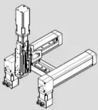
Three-dimensional gantry
natural_image
Technical line drawing of a mechanical assembly with no visible text or symbolsFESTO
Festo SE & Co. KG
Ruiter Straße 82
73734 Esslingen
Deutschland
+49 711 347-0
www.festo.com
Operating instructions
8170131
2022-03a
[8170133]

8170131
Translation of the original instructions
© 2022 all rights reserved to Festo SE & Co. KG
1 About this document
1.1 Applicable documents
i
All available documents for the product www.festo.com/sp.
i
The area of application and the approvals of the individual components of the kit are described in separate documents → www.festo.com/sp.
Download configuration-dependent documents
The technical data for the product are described in configuration-dependent documents.
These documents form part of the product documentation and can be downloaded as follows.
-
Read the order ID of the product.
-
Download the documents from the Festo Support Portal by entering the order ID → www.festo.com/sp.
-
Print out the documents and keep them together with these operating instructions.
2 Safety
2.1 General safety instructions
- Only use the product in its original condition without unauthorised modifications.
-Only use the product if it is in perfect technical condition. - Observe labelling on the product.
- Before working on the product, switch off the power supply and secure it against being switched on again.
-Observe tightening torques. Unless otherwise specified, the tolerance is ± 20% .
2.2 Intended use
The intended use of the product is to execute positioning tasks within machines or automation systems with a higher-order controller in an industrial environment.
2.3 Foreseeable misuse
Never use the product as follows:
- With unauthorised modifications or alterations to the product
-With load limits exceeded - In an invalid mounting position
3 Additional information
- Contact the regional Festo contact if you have technical problems
→ www.festo.com. - Accessories and spare parts → www.festo.com/catalogue.
4 Product overview
3-dimensional gantry XY module type Z module type
| YXMR-1 EXCM-30 DHMZ-DGSL-8/- | 10/-12 | EHMZ-EGSC-25/-32 |
| YXMR-2 EXCM-40 DHMZ-DGSL-16 | EHMZ-EGSL-45 | |
| EXCH-40 | ||
| YXMR-3 EXCH-60 DHMZ-DGSL-20 | EHMZ-EGSL-55 |
Tab. 1: Product allocation
Product labelling
In addition to product labelling of individual components, the product also has configuration-specific, higher-order product labelling in accordance with the following schematic:
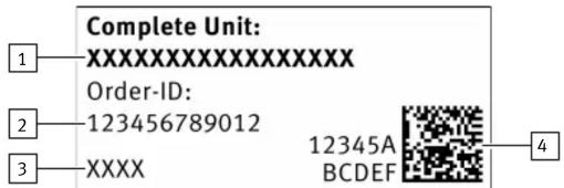
Fig. 1: Configuration-specific product labelling
1 Product name
2 Configuration-specific order ID
3 Festo serial number
4 Configuration-specific Product Key
The configuration-specific, higher-order product labelling is attached to all products at a specifically defined position.

natural_image
Technical line drawing of a mechanical assembly with no visible text or symbolsFig. 2: Position of higher-order product labelling, EXCM-30 as example
1 Position of higher-order product labelling
5 Assembly
5.1 Demounting/mounting motors
DANGER
Serious injuries due to the motor falling from an elevated position.
- Demount motors with brake before assembling the product.
- Before loosening the retaining screws: secure the motor against falling.
WARNING
Electric shock.
- Make sure that the motors are disconnected from the power supply.
NOTICE
Third-party motors with a driving torque that is too high can damage the product. When using third-party motors observe the following:
• Maximum approved driving torque → www.festo.com/catalogue
- Attachment dimensions motor interface www.festo.com/catalogue
- Matching combination of coupling, coupling housing and motor flange
Motor attachment position bottom/top

Fig. 3: EXCH-40-...-B and EXCH-40-...-T shown, examples of motors
1 Motor flange
3 Motor, example
2 Retaining screw, 4x
Demounting
- Disconnect the connections of the motor cables and encoder cables from the motors.
- Demount the 2 motors by unscrewing the 4 retaining screws on each motor.
- Remove the motors.
EXCH-40 with motor only: also remove the motor flange.
With other variants: the motor flanges are attached separately, do not demount.
Mounting
- For motors with brake:
Set or keep the Y-axis and the Y-axis slide at least 10 cm apart:
-Between Y-axis and drive cover or end cap
-Between Y-axis slide and X-axis
The Y-axis and the Y-axis slide must be movable in both directions for the subsequent insertion of the motors.
- Mount the 2 motors with the motor flanges in reverse order of demounting.
| Tightening torque EXCM-30 | EXCM-40 | EXCH-40 | EXCH-60 | |
| Retaining screws [Nm] 1.2 3.0 6.0 18.0 | ||||
With other variants: the motor flanges are attached separately.
- Connect the motor cables and encoder cables to the motors.
5.2 Adjust motor cable outlets
DANGER
Serious injuries due to the motor falling from an elevated position.
- Before loosening the motor attachment screws: secure motor from falling down.
DANGER
Serious crushing by falling of the Y-axis.
The Y-axis is retained by the active motor brakes.
If the retaining screws are released on both motors, the Y-axis will no longer be retained and will drop.
- Unscrew the retaining screws on only one motor at a time.
WARNING
Electric shock.
- Disconnect the motor controller from the power supply if it is already connected.
Dangerous residual voltage even after the power supply is switched off.
- Wait at least one minute after switching off the power supply. Do not start work until the residual voltage has fallen below 60 V.
The position of the motor cable outlets on the planar surface gantry is factory-installed in the X-axis extension. If necessary, the position can be adapted to the installation situation by turning the motor in 90°-steps.
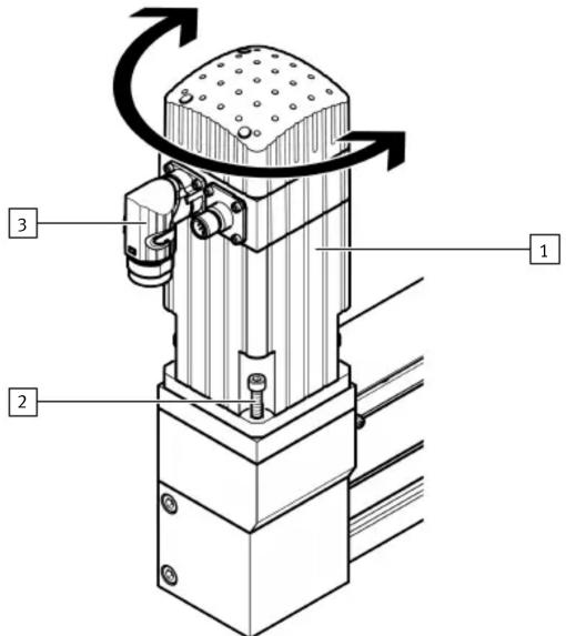
Fig. 4: EXCH-40-...-T shown, motor example
1 Motor, example
2 Retaining screw, 4x
3 Motor cable outlets for motor cable and encoder cable
Procedure
- For motors with brake:
When the motor is rotated, the Y-axis and the Y-axis slide are moved.
Set a distance of at least 10 cm to allow this movement:
-Between Y-axis and drive cover or end cap
-Between Y-axis slide and X-axis
-
Disconnect connected motor cable and encoder cable from the motor.
-
Unscrew the 4 retaining screws.
-
Rotate the motor to the desired position.
The Y-axis and the Y-axis slide are moved with motors with brake.
- Tighten the retaining screws.
| Tightening torque EXCM-30 | EXCM-40 | EXCH-40 | EXCH-60 |
| Retaining screws [Nm] 1.2 | 3.0 | 6.0 | 18.0 |
- Connect the motor cable and encoder cable to the motor.
If necessary, repeat the procedure for the other motor.
6 Technical data
i
Non-compliance with the technical data will damage the product.
The technical data are included in various documents:
-General technical data → www.festo.com/catalogue.
- Configuration-dependent technical data in the data sheet
→ www.festo.com/sp.
- Three-dimensional gantry
- FESTO
- About this document
- Applicable documents
- Download configuration-dependent documents
- Safety
- General safety instructions
- Intended use
- Foreseeable misuse
- Additional information
- Product overview
- Product labelling
- Assembly
- Demounting/mounting motors
- DANGER
- WARNING
- NOTICE
- Demounting
- Mounting
- Adjust motor cable outlets
- Procedure
- Technical data
Brand : Festo
Model : YXMR-2
Category : Système de positionnement industriel