DKFD-60L - Car audio interface CRUX - Free user manual and instructions
Find the device manual for free DKFD-60L CRUX in PDF.


| Product Type | Food Dehydrator |
| Model | DKFD-60L |
| Brand | CRUX |
| Dimensions (H x W x D) | 12 x 14 x 14 inches |
| Weight | 8 lbs |
| Power Consumption | 600 W |
| Number of Trays | 6 |
| Temperature Range | 95°F to 165°F (35°C to 74°C) |
| Timer | Up to 24 hours |
| Material | Plastic housing, stainless steel mesh trays |
| Functions | Drying fruits, vegetables, herbs, meat jerky, yogurt |
| Control Type | Digital display with touch controls |
| Cleaning | Removable trays, wipe clean body with damp cloth |
| Safety Features | Overheat protection, auto shut-off, cool-touch handle |
| Spare Parts Availability | Replacement trays and filters available from CRUX |
| Repairability | User-replaceable fuse and thermostat; professional repair recommended for motor issues |
Frequently Asked Questions - DKFD-60L CRUX
User questions about DKFD-60L CRUX
0 question about this device. Answer the ones you know or ask your own.
Ask a new question about this device
Download the instructions for your Car audio interface in PDF format for free! Find your manual DKFD-60L - CRUX and take your electronic device back in hand. On this page are published all the documents necessary for the use of your device. DKFD-60L by CRUX.
USER MANUAL DKFD-60L CRUX
- Retains factory features with an aftermarket radio.
- Retains factory-installed Subwoofer.
- Retains Steering Wheel Controls via built-in, pre-programmed interface.
- With navigation outputs (Reverse gear, Illumination and Speed signal).
- Provides Accessory Power (2A MAX).
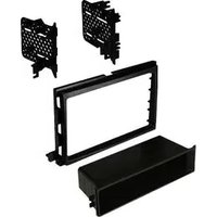
- Includes dusk kit (double DIN or single DIN with pocket).
PARTS INCLUDED:

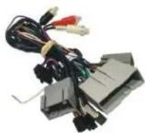
natural_image
Electrical connector with multiple wires and connectors (no visible text or symbols)

SWRFD-60L MODULE SWRFD-60L HARNESS Antenna Adapter SWC CABLE

natural_image
Technical line drawing of a rectangular electronic component with internal slots and mounting brackets (no text or symbols)
natural_image
Pure mechanical linkage diagram without any text, numbers, or symbols
natural_image
Line drawing of a rectangular electronic device with a recessed top and side slot (no text or symbols)INSTALLATION DIAGRAM:
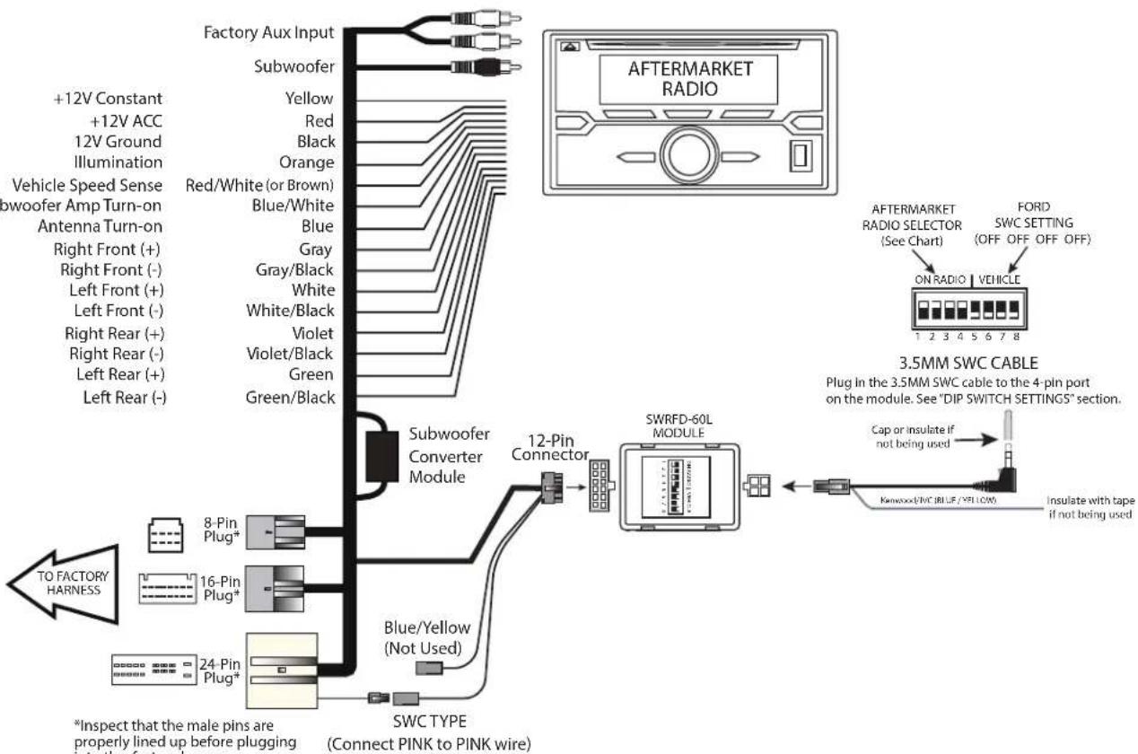
flowchart
graph TD
    A["Factory Aux Input"] --> B["Subwoofer"]
    B --> C["Yellow"]
    C --> D["Red"]
    D --> E["Black"]
    E --> F["Orange"]
    F --> G["Red/White (or Brown)"]
    G --> H["Blue/White"]
    H --> I["Blue"]
    I --> J["Gray"]
    J --> K["Gray/Black"]
    K --> L["White"]
    L --> M["White/Black"]
    M --> N["Violet"]
    N --> O["Violet/Black"]
    O --> P["Green"]
    P --> Q["Green/Black"]
    Q --> R["Subwoofer Converter Module"]
    R --> S["12-Pin Connector"]
    S --> T["SWRFD-60L MODULE"]
    T --> U["ON RADIO VEHICLE"]
    U --> V["3.5MM SWC CABLE"]
    V --> W["Plug in the 3.5MM SWC cable to the 4-pin port on the module. See "DIP SWITCH SETTINGS" section."]
    V --> X["Cap or insulate if not being used"]
    V --> Y["Insulate with tape if not being used"]
    V --> Z["Kanwoo(RVC,BLUE,VELLOW)."]
LED TROUBLESHOOTING ON MODULE
| LED LIGHT | LED MODULE FEEDBACK | |
| BLUE LED OFF | NO POWER | CHECK VOLTAGE |
| RED LED FLASHES | WHEN PRESSING SWC BUTTONS | |
NOTES:
- Only supports analog Steering Wheel Control type.
- Use part number SWRFD-60 for CAN Bus Steering Wheel Control.
- Output signal stated above may not cover all Year/Model.
- Does not retain SYNC.
- Not compatible with factory-installed Sony systems and THX systems with amplifier.
ANALOG CONNECTION:
HOW TO DETERMINE IF THE VEHICLE HAS ANALOG SWC:
Analog Steering Wheel Control (SWC) signal vehicles will have wires populated and line up to the PINK and BLACK wire on the 24-Pin Crux connector.
If one wire is missing then you will need to use Crux part number SWRFD-60.

Crux 24-Pin Connector
DIP SWITCH SETTINGS:
AFTERMARKET RADIO DIP SWITCH SETTINGS:
| RADIO BRAND: | DIP: | 1 | 2 | 3 | 4 |
| Atoto, Dual, Farenheit, Jensen, Pioneer | OFF | OFF | ON | ON | |
| Power Acoustik, Soundstream | OFF | OFF | ON | ON | |
| Blaupunkt, Most off-brand Radios | OFF | OFF | ON | ON | |
| Alpine | OFF | OFF | OFF | OFF | |
| Clarion | OFF | ON | ON | OFF | |
| Kenwood | OFF | ON | ON | ON | |
| JVC | OFF | ON | OFF | ON | |
| Boss, Old Sony | OFF | ON | OFF | OFF | |
| New Sony | OFF | OFF | ON | OFF | |

NOTE: For Atoto, Blaupunkt, Dual, Farenheit, Power Acoustik, Soundstream, and most off-brand radios, check the aftermarket radio's manual to see if the SWC buttons need to be programmed.
FORD STEERING WHEEL CONTROL DIP SWITCH SETTING:
| DIP: | 5 | 6 | 7 | 8 | |
| Ford | OFF | OFF | OFF | OFF | |

3.5MM SWC CABLE
Plug in the 3.5MM to 4-Pin SWC cable to the SWC module.
NOTE: Insulate the Blue/Yellow and Green wires if not being used.
For aftermarket radios that have wires for SWC connections, cut off the 3.5mm plug on the Crux SWC Cable (option B) and connect the SWC wires as follows:
Note that there are some radios that only have SWC1 and SWC2, in this case "shield" does not need to be connected.

RED to SWC Key 1 WHITE to SWC Key 2 SHIELD to SWC Ground
VEHICLE APPLICATIONS:
| FORD | LINCOLN | ||
| 2007 – 2010 | Edge | 2006 – 2008 | Mark LT |
| 2008 – 2012 | Escape** | 2007 – 2010 | MKX (Nav only) |
| 2007 – 2010 | Expedition | 2007 – 2011 | Navigator (Nav only) |
| 2006 – 2010 | Explorer | ||
| 2007 – 2010 | Explorer Sport Trac | MERCURY | |
| 2009 – 2008 | F-150 | 2008 – 2010 | Mariner** |
| 2009 – 2012 | F-150* | 2006 – 2009 | Milan |
| 2008 – 2012 | F-Series Super Duty | 2005 – 2007 | Montego |
| 2005 – 2007 | Five Hundred | 2004 – 2007 | Monterey |
| 2007 – 2008 | Focus | 2006 – 2010 | Mountaineer |
| 2004 – 2007 | Freestar | 2008 – 2009 | Sable |
| 2005 – 2007 | Freestyle | ||
| 2006 – 2009 | Fusion | MAZDA | |
| 2005 – 2009 | Mustang | 2009 – 2011 | Tribute** |
| 2008 – 2009 | Taurus | ||
*Not compatible on vehicles equipped with acclimated radio/climate control panel.
**Compatible with vehicles equipped with factory navigation radio only.
Compatible Ford SWC Types:
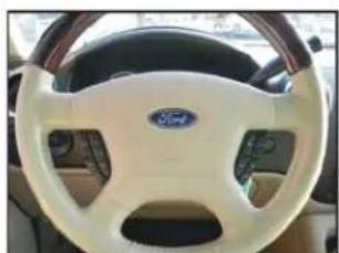
natural_image
Interior view of a car dashboard showing the Ford logo and white steering wheel (no text or symbols visible)Type 1 4-Button

natural_image
Interior view of a car dashboard with the Ford logo and steering wheel (no visible text or symbols)Type 2 4-Button

natural_image
Interior view of a car dashboard with steering wheel and dashboard gauges (no visible text or symbols)Type 3 5-Button
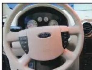
natural_image
Interior view of a car dashboard with white steering wheel and black dashboard (no visible text or symbols)Type 4 6-Button

1. Insert ISO bracket store a rokitashown in Figure A
2. Insert pocket to lower section of it from rear lock not so sf mounting brackets.
3. Insert ISO mountableri di between ISO mount brackets and loosely attachiosides of radious inscrews provided with radio when possible ress supplied with kit.
4. Slider adiorwardor backward orls desired look and flightersrews.
5. Attachare support bracket to therear of thenewradio and adjustas necessary to suppu r theweight other radio (Optional).
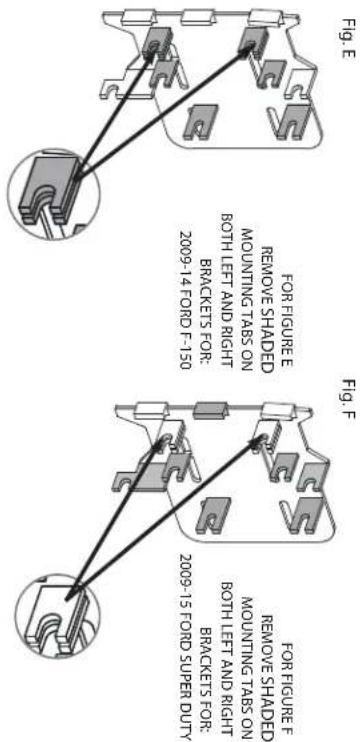


For all vehicles listed below, remove the shaded mounting tabs on both left and right brackets.
BRACKET PREPARATION
| DASH DISASSEMBLY INSTRUCTIONS |
| NOTE: SeeIllustrationDonpage2forbracketpreparation1. Carefullyunlpandremovetheradio/climatecontrolrimbezelforaroundthefactoryradio,Disconnecttheharnessesfromtherearotheradio/climatecontrolbezelandremovebezel.3. Removethe(4)9/32screwssecuringtherafactoryradiotothesub-dash.4. Carefullypullradioforward disconnectethwireharnessandantennaleadfromthefactoryradioandremoveradio.2006-10 FORD EXPLORER2006-10 MERCURY MOUNTAINEER (NAV ONLY)2007-10 EXPLORER SPORT TRAC |
| DASH DISASSEMBLY INSTRUCTIONS |
| NOTE: SeeIllustrationConpage2forbracketpreparation1. Openthecenterconsoleandremovethe(2)8/32screwsfromthecenterconsoleshifterim.2. Carefullylufoponthecenterconsoleshiftertrimanddisconnectthe12voltreceptacloharnessandremovtrim.3. Carefullycryoutwardtheradiotrimbezeltoreleasethepanelclips,thenlifethowersidesupwardandslightlyoutwardioclearthesthifler4. Disconnectialharmessesfromtheradiotrimbezelandremovebezel.5. Removethe(4)9/32screwssecuringtheradiotothesub-dash.6. Pullradioforward,disconnectalharmessesandantennaleadandremoveradio.2006-09 FORD FUSION2006-08 LINCOLN ZEPHYR2006-09 MERCURY MILAN |
| DASH DISASSEMBLY INSTRUCTIONS |
| NOTE: SeeIllustrationConpage2forbracketpreparation1. Startingfromthebottom,carefullyryrhefactoryradiotrimbeziforaroundthefactoryradioforward,disconnectalharmessesattachedotherearotherfetrimbezelandremovebezel.2. Removethe(4)9/32screwssecuringtheradiotothesub-dash.3. Carefullypullradioforward,disconnecta lihnassesandantennaleadandremoveradio.2008-11 FORD ESCAPE2008-11 MAZDA TRIBUTE/MERCURY MARINER |
| DASH DISASSEMBLY INSTRUCTIONS |
| NOTE: SeeIllustrationDonpage2forbracketpreparation1. CarefullyrytheVentassemblyabovetheradioforward,ethesub-dash.2. Removethe(2)9/32screwssecuringthetopftheradio/Climatecontrolassemblytoattachedharmessesandremovepanel.4. Removethe(2)9/32screwssecurngtn assembly.5. Setthebarkindbrake. |
| NOTE: SeeIllustrationConpage2forbracketpreparation1. Startingfromthebottom,carefullyryrhefactoryradiotrimbeziforaroundthefactoryradioforward,disconnectalharmessesattachedotherearotherfetrimbezelandremovebezel.2. Removethe(4)9/32screwssecuringtheradiotothesub-dash.3. Carefullypullradioforward,disconnecta lihnassesandantennaleadandremoveradio.2008-11 FORD ESCAPE2008-11 MAZDA TRIBUTE/MERCURY MARINER |
| DASH DISASSEMBLY INSTRUCTIONS |
| NOTE: SeeIllustrationDonpage2forbracketpreparation1. CarefullyrytheVentassemblyabovetheradioforward,ethesub-dash.2. Removethe(2)9/32screwssecuringthetopftheradio/Climatecontrolassemblytoattachedharmessesandremovepanel.4. Removethe(2)9/32screwssecurngtn assembly.5. Setthebarkindbrake. |
Brand : CRUX
Model : DKFD-60L
Category : Car audio interface