MM-OG-26 - Programmable Logic Controller ENTES - Free user manual and instructions
Find the device manual for free MM-OG-26 ENTES in PDF.


| Product Type | Expansion Module for MPR-4 Series Analyzers |
| Model | MM-OG-26 |
| Brand | ENTES |
| Digital Inputs | 2 (configurable: logical input, pulse input, or generator input) |
| Digital Outputs | 2 (configurable: pulse output, alarm based, or remote control) |
| Analog Outputs | 2 (0-20 mA, 4-20 mA, 0-24 mA, or voltage outputs: ±5 V, ±10 V, 0-5 V, 0-10 V) |
| Relay Outputs | 2 |
| Supported Measurements | Voltage (phase-neutral, phase-phase), Current (phase, neutral, demand), Active/Reactive/Apparent Power, Cos Phi, Frequency, Energy totals |
| Communication | Pulse output, analog output, Modbus register access for remote control |
| Pulse Width Settings | 40 ms to 500 ms (9 selectable options) |
| Analog Output Scaling | Configurable low and high values for each parameter |
| Installation | Plug-in module for MPR-4 series; power must be off during connection |
| Safety | Installation only by qualified personnel; do not operate in humid environments; never open cover when powered |
| Operating Environment | Avoid water and moisture; use within specified supply voltage range |
| Dimensions | Not specified in manual |
| Weight | Not specified in manual |
Frequently Asked Questions - MM-OG-26 ENTES
User questions about MM-OG-26 ENTES
0 question about this device. Answer the ones you know or ask your own.
Ask a new question about this device
Download the instructions for your Programmable Logic Controller in PDF format for free! Find your manual MM-OG-26 - ENTES and take your electronic device back in hand. On this page are published all the documents necessary for the use of your device. MM-OG-26 by ENTES.
USER MANUAL MM-OG-26 ENTES
Pulse Output Menu
Σ+EA Q14 = Total Imported Active Energy (Q14)
Σ-EA Q23 = Total Exported Active Energy (Q23)
Σ+ER Q1 = Total Imported Reactive Energy in Zone 1
Σ-ER Q4 = Total Exported Reactive Energy in Zone 4
Σ+ER Q2 = Total Imported Reactive Energy in Zone 2
Σ-ER Q3 = Total Exported Reactive Energy in Zone 3
ΣES Q14 = Q14 Total Imported Apparent Energy
Σ-FS O23 = O23 Total Exported Apparent Energy
+FAI 1 = 1. Phase Active Energy (Import)
+EAL1 = 1. Phase Active Energy (Import)
+EAL2 = 3. Phase Active Energy (Import)
+EAL2 = 2. Phase Active Energy (Import) +EAL3 = 3. Phase Active Energy (Import)
+EA LS = 3. Phase Active Energy (Import)
Pulse outputs produce one pulse per "Pulse width" period set in
accordance with the rate of increment for each "Pulse Rate". Duty
indicates the minimum waiting time between each pulse. If the interval
between triggered pulses is shorter than the minimum waiting time, pulses
are recorded to the device memory. These recorded pulses will be sent
recursively.
ANALOG OUTPUT MODULE
Device enables other devices to monitor and display measured values by transforming them to current data at intervals of (0-20) (4-20) (0-24) mA or to voltage data at intervals of (±5) (±10) (0-5) (0-10) V. There are 2 analog outputs in the device.
The device can perform outputs based on the parameters below:
VLN1, VLN2, VLN3, VLN4 (Phase-Neutral Voltage)
VENT, VENZ, VENS, VEN4 (V) (Phase-Neutral VUL1, VUL2, VUL3 0/0) (Phase Phase Voltages)
VEL1, VEL2, VEL3 (V) (Phase-Phase II.4, II.2, II.3, II.4 (A) (Phase Currents)
IL1, IL2, IL3, IL4 (A) (Phase Currents) IN (A) (Neutral Currents)
IN (A) (Neutral Currents)
IL1 DMN, IL2 DMN, IL3 DMN, IL4 DMN (A) (Phase
Current Demands)
IN DMN (A) (Neutral Current Demands)
P1. P2. P3 (kW) (Active Power)
Q1. Q2. Q3 (kVAr) (Reactive Po
S1 S2 S3 (kVA) (Apparent Power)
SP (kW) (Total Active Power)
SP (MP (kW) (Imported Active Power Total))
ZP IMP (KW) (Imported Active Power Total)
ZP EXR (KW) (Exported Active Power Total)
ZP EXP (kW) (Exported Active Power
SO (kVAr) (Total Reactive Power)
ZQ (kVAR) (Total Reactive Power)
ΣQ QUAD1, ΣQ QUAD2, ΣQ QUAD3, ΣQ
QUAD4 (kVAr) (Reactive Power in Different Zones)
ΣS (kVA) (Total Apparent Power)
ΣS IMP (kVA) (Total Imported Apparent Power)
ΣS EXP (kVA) (Total Exported Apparent Power
ΣP IMP D (kW) (Total Imported Active Power D
SP EXP D (kW) (Total Exported Active Power Demand
ΣS IMP D (kVA) (Total Imported Apparent Power Demand)
ΣS EXP D (kVA) (Total Exported Apparent Power Demand)
23 EXP-D (kVA) (Total Exported Apparent Power Demand)
COSm1 (Cos Rbi Phase 1)
COSφ1 (Cos Phi Phase 1) COSφ2 (Cos Phi Phase 2)
COSφ2 (Cos Phi Phase 2)
COSφ3 (Cos Phi Phase 3)
ΣP COSφ (Total Cos Phi)
Hz (Hz) (Frequency)
For Example:
By navigating in the Settings Menu of the device, you
By navigating in the Octang's Menda of the device, y may make the following respective configurations:
Type: 0-30 mA
Type: 0-20 mA
Resem (Resem
Param (Parameter): VLENT Low (Low Value): 90 V
Low (Low value): 90 V High (High Value): 200
High (High value): 300 V
After making the above configurations, analog output will be 2 mAhon ML4 units to 30 V and below used.
will be 0 mA when VL1 value is 90 V and below; and
analog output will be 20 mA when VL1 value is 300 V
and above.
If VLN1 is 220 V, this value will be;

(四) 本次股东大会的召集和召开程序

flowchart
graph TD
    A["Alarm"] --> B["Alarm-1"]
    A --> C["Alarm-2"]
    A --> D["Alarm-Active"]
    B --> E["Switches to the settings, when Active/Active is found"]
    C --> E
    D --> E
    E --> F["Alarm Param."]
    F --> G["Alarm Limit"]
    G --> H["Upper Limit"]
    G --> I["Lower Limit"]
    style A fill:#f9f,stroke:#333
    style B fill:#ccf,stroke:#333
    style C fill:#ccf,stroke:#333
    style D fill:#ccf,stroke:#333
    style E fill:#cfc,stroke:#333
    style F fill:#cfc,stroke:#333
    style G fill:#cfc,stroke:#333
    style H fill:#fcc,stroke:#333
    style I fill:#fcc,stroke:#333
Output=(20-0)x(220-90)(300-90)=12.38\ mA

flowchart
graph TD
    A["Alarm Param."] --> B["Alarm Limit"]
    B --> C["Upper Limit"]
    C --> D["Lower Limit"]
    D --> E["Hysteresis (%)"]
    E --> F["On Delay (x)"]
    F --> G["Off Delay(s)"]
    G --> H["Output Port"]

    subgraph Upper Limit
        I1["1"] --> J1["low"]
        I2["2"] --> J2["low"]
        I3["3"] --> J3["low"]
        I4["4"] --> J4["low"]
        I5["5"] --> J5["low"]
        I6["6"] --> J6["low"]
        I7["7"] --> J7["low"]
        I8["8"] --> J8["low"]
        I9["9"] --> J9["low"]
        I10["10"] --> J10["low"]
    end

    subgraph Lower Limit
        J1 --> K1["moderate"]
        J2 --> L1["moderate"]
        J3 --> M1["moderate"]
        J4 --> N1["moderate"]
        J5 --> O1["moderate"]
        J6 --> P1["moderate"]
        J7 --> Q1["moderate"]
    end

    subgraph Hysteresis
        R1["1"] --> S1["high"]
        R2["2"] --> S2["high"]
        R3["3"] --> S3["high"]
        R4["4"] --> S4["high"]
        R5["5"] --> S5["high"]
        R6["6"] --> S6["high"]
        R7["7"] --> S7["high"]
        R8["8"] --> S8["high"]
        R9["9"] --> S9["high"]
    end

    subgraph Output Port
        T1["1"] --> U1["low"]
        T2["2"] --> U2["low"]
        T3["3"] --> U3["low"]
        T4["4"] --> U4["low"]
        T5["5"] --> U5["low"]
        T6["6"] --> U6["low"]
        T7["7"] --> U7["low"]
        T8["8"] --> U8["low"]
    end

    style Upper Limit fill:#f9f,stroke:#333
    style Lower Limit fill:#f9f,stroke:#333
    style Hysteresis fill:#ccf,stroke:#333


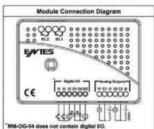
Note: The contact resistance at ohmic load (e.g.: Incandescent bulb, Resistance devices) is 5A. It is recommended to use a contactor if the inductive load e.g.: AC motor, fluorescent, etc.) or capacitive load (e.g.: Led Drivers, UPS, Fluorescent (Electronic Ballast), etc.) switch. Otherwise adhesion may occur in relay contacts.
ENTES Elektronik Cihazlar Imalat ve Ticaret A.S.
Address : Dudullu OSB; 1. Cadde; No: 23 34776 Umraniye - ISTANBUL / TURKE
Tel : +90 216 313 01 10 Fax : +90 216 314 16 15 E-mail: contact@entes.eu
Web: www.entes.eu

A7610/Rev.3
01.12.2019
MPR-4 SERİSİ MODÜLLERİ
E/NTES
MM-OG-26; 2 DİJITAL GİRİŞ, 2 DİJITAL ÇIKİŞ, 2 ANALOG ÇIKİŞ, 2 RÖLE ÇIKİŞLI MODÜL MM-OG-04; 2 ANALOG ÇIKİŞ, 2 RÖLE ÇIKİŞLI MODÜL
IN (A) (Not Atm) IL 1 DMN IL 2 DMN
IL1 DMN, IL2 DMN, IL3 DMN, IL4DMN (A) (Paz A. Dema. IN DMN (A) (NI) Alex Respond)
IN DMN (A) (Notr Akim Der
P1, P2, P3 (kW) (Aktif Güç)
Q1, Q2, Q3 (kVAr) (Reaktif Güç)
COSφ1 (Cos Phi Faz 1)
COSφ2 (Cos Phi Faz 2)
COSφ3 (Cos Phi Faz 3)
ΣP COSφ (Toplam Cos Phi)
Hz (Hz) (Frekans)

WARNING : Installation of this device must be carried out only by qualified personnel. Please read this manual carefully before installation. 1. Before connecting the module, turn off the power of the MPR4 series Analyzer device. If the module is plugged in when the MPR4 is powered, the device will not recognize the module
- Before connecting the device, make sure you turn off the power line connecting to the device on the panel.
-
Before connecting the device, by controlling the back panel of the device, make sure the device is connected to the right power terminals with matching voltage levels.
-
You should not connect the device to the network if it is malfunctioning.
-
In order to prevent electrical damage, avoid humid environments and operate the device far from water.
-
Never open the cover of the device when powered
-
Always use in the suggested supply voltage range
The following table
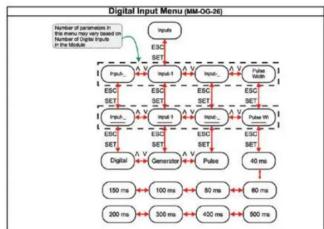
Digital Inputs
There are 2 digital options for MM-OG-26 only.
Input Parameter Settings
- Digital Input: If you select this feature, logical input value will be used. By reading the value in Modbus register (H : 0xA0), you can understand whether the device is on logic-1 or logic-0 input level.
2.Pulse Input: If you select this feature, incoming pulses to the input will be
counted. 3.Generator Input: If you select this feature, energy values are saved to the generator register, when the input level is logic-0.
Pulse Width Setting
Minimum amount of time required to make the device count the number of pulses are set in accordance with the values below:
- 40 milliseconds
- 60 milliseconds
- 80 milliseconds
- 80 milliseconds
- 60 milliseconds
- 100 milliseconds
- 500 milliseconds
Pulse Input Menu
In this menu, you can activate the Pulse-Meter. If pulses on the input are in line with the value assigned via "Pulse Width Settings" menu, the Pulse-Meter should increase based on these settings. You can view active "Pulse-Meters" on the main menu in the presence of the pulse at input
flowchart
graph TD
    A["Input"] --> B["ESC"]
    B --> C["Micro"]
    C --> D["ESC"]
    D --> E["Micro"]
    E --> F["ESC"]
    F --> G["Micro"]
    G --> H["ESC"]
    H --> I["Micro"]
    I --> J["ESC"]
    J --> K["Micro"]
    K --> L["ESC"]
    L --> M["Micro"]
    M --> N["ESC"]
    N --> O["Micro"]
    O --> P["ESC"]
    P --> Q["Micro"]
    Q --> R["ESC"]
    R --> S["Micro"]
    S --> T["ESC"]
    T --> U["Micro"]
    U --> V["ESC"]
    V --> W["Micro"]
    W --> X["ESC"]
    X --> Y["Micro"]
    Y --> Z["ESC"]
    Z --> AA["Micro"]
    AA --> AB["ESC"]
    AB --> AC["Micro"]
    AC --> AD["ESC"]
    AD --> AE["Micro"]
    AE --> AF["ESC"]
    AF --> AG["Micro"]
    AG --> AH["ESC"]
    AH --> AI["Micro"]
    AI --> AJ["ESC"]
    AJ --> AK["Micro"]
    AK --> AL["ESC"]
    AL --> AM["Micro"]
    AM --> AN["ESC"]
    AN --> AO["Micro"]
    AO --> AP["ESC"]
    AP --> AQ["Micro"]
    AQ --> AR["ESC"]
    AR --> AS["Micro"]
    AS --> AT["ESC"]
    AT --> AU["Micro"]
    AU --> AV["ESC"]
    AV --> AW["Micro"]
    AW --> AX["ESC"]
    AX --> AY["Micro"]
    AY --> AZ["ESC"]
    AZ --> BA["Micro"]
    BA --> BB["ESC"]
    BB --> BC["Micro"]
    BC --> BD["ESC"]
    BD --> BE["Micro"]
    BE --> BF["ESC"]
    BF --> BG["Micro"]
    BG --> BH["ESC"]
    BH --> BI["Micro"]
    BI --> BJ["ESC"]
    BJ --> BK["Micro"]
    BK --> BL["ESC"]
    BL --> BM["Micro"]
    BM --> BN["ESC"]
    BN --> BO["Micro"]
    BO --> BP["ESC"]
    BP --> BQ["Micro"]
    BQ --> BR["ESC"]
    BR --> BS["Micro"]
    BS --> BT["ESC"]
    BT --> BU["Micro"]
    BU --> BV["ESC"]
    BV --> BW["Micro"]
    BW --> BX["ESC"]
    BX --> BY["Micro"]
    BY --> BZ["ESC"]
    BZ --> CA["Micro"]
    CA --> CB["ESC"]
    CB --> CC["Micro"]
    CC --> CD["ESC"]
    CD --> CE["Micro"]
    CE --> CF["ESC"]
    CF --> CG["Micro"]
    CG --> CH["ESC"]
    CH --> CI["Micro"]
    CI --> CJ["ESC"]
    CJ --> CK["Micro"]
    CK --> CL["ESC"]
    CL --> CM["Micro"]
    CM --> CN["ESC"]
    CN --> CO["Micro"]
    CO --> CP["ESC"]
    CP --> CQ["Micro"]
    CQ --> CR["ESC"]
    CR --> CS["Micro"]
    CS --> CT["ESC"]
    CT --> CU["Micro"]
    CU --> CV["ESC"]
    CV --> CW["Micro"]

flowchart
graph TD
    A["The number of parameters in this menu may vary based on the number of Digital Outputs in the Module"] --> B["Outputs"]
    B --> C["ESC"]
    C --> D["SET"]
    D --> E["Output_1"]
    E --> F["ESC"]
    F --> G["SET"]
    G --> H["Output_2"]
    H --> I["ESC"]
    I --> J["SET"]
    J --> K["Pulse"]
    K --> L["V1"]
    L --> M["Alarm"]
    M --> N["V1"]
    N --> O["Remote"]

flowchart
graph TD
    A["Input"] --> B["Input-1"]
    B --> C["ESC"]
    C --> D["SET"]
    D --> E["Pulse Input"]
    E --> F["ESC"]
    F --> G["SET"]
    G --> H["Input-1 Rate"]
    H --> I["ESC"]
    I --> J["SET"]
    J --> K["Active"]
    K --> L["Passive"]
    L --> M["00000"]
    N["Number of parameters in this menu may vary based on the number of digital inputs in the Module"] --> A
    O["Input Rate Menu is only visible for inputs with Activated Pulse Feature"] --> H

flowchart
graph TD
    A["SET"] --> B["ESC"]
    B --> C["Output"]
    C --> D["ESC"]
    D --> E["Output Parameter"]
    E --> F["ESC"]
    F --> G["Disable"]
    G --> H["S-EA Q14"]
    H --> I["Z-EA Q23"]
    I --> J["Z-ER Q1"]
    J --> K["Z-ER Q4"]
    K --> L["Z-ER Q2"]
    L --> M["Z-ER Q3"]
    M --> N["EES Q14"]
    N --> O["S-EB Q23"]
    O --> P["-EAL1"]
    P --> Q["-EAL2"]
    Q --> R["-EAL3"]
    B --> S["ESC"]
    S --> T["Pulse Rate"]
    T --> U["ESC"]
    U --> V["S-BT"]
    V --> W["ESC"]
    W --> X["ESC"]
    X --> Y["S-BT"]
    Y --> Z["1"]
    Z --> AA["Sup 0.00"]
    AA --> AB["Sale 0.00"]
    AB --> AC["ESC"]
    AC --> AD["S-BT"]
    AD --> AE["ESC"]
    AE --> AF["S-BT"]
    AF --> AG["ESC"]
    AG --> AH["S-BT"]
    AH --> AI["ESC"]
    AI --> AJ["S-BT"]
    AJ --> AK["ESC"]
    AK --> AL["S-BT"]
    AL --> AM["Sale 0.00"]
Digital Outputs
There are 2 digital outputs for MM-OG-26 only..
Output Parameter Settings
- Pulse Output: "Pulse Output" in the Settings display is activated and the pulse output of the device is adjusted based on the parameters you set.
- Alarm Based Output: When an alarm is created, the output of the logic level will be set to zero.
- Remote Output: By assigning a value to Modbus register (H : 0xA1), the output level is set to logic-0 or logic-1. By doing so, you can change the remote output and trigger an external device.
This menu is only active for devices which has pulse output feature.
Brand : ENTES
Model : MM-OG-26
Category : Programmable Logic Controller