MC-E - Cutting machine Maruyama - Free user manual and instructions
Find the device manual for free MC-E Maruyama in PDF.


| Product Type | Brush Cutter / String Trimmer |
| Brand | Maruyama |
| Model | MC-E |
| Engine Displacement | 25.4 cc (estimated) |
| Power Output | 0.9 kW (1.2 hp) (estimated) |
| Cutting Width | 45 cm (18 inches) (estimated) |
| Cutting Head Type | Tap-and-go bump feed nylon line head |
| Line Diameter | 2.0 mm (0.080 inches) (estimated) |
| Fuel Type | Unleaded gasoline mixed with 2-stroke oil (50:1 ratio) |
| Fuel Tank Capacity | 0.5 L (estimated) |
| Weight (without fuel) | 5.5 kg (12.1 lbs) (estimated) |
| Overall Length | 180 cm (71 inches) (estimated) |
| Shaft Type | Straight shaft with solid steel drive |
| Handle Type | J-style handle with anti-vibration system |
| Ignition System | Electronic transistor ignition |
| Starter System | Easy-start recoil starter |
| Primary Functions | Grass trimming, weed cutting, light brush clearing |
| Safety Features | Throttle trigger lockout, blade guard, anti-vibration handles |
| Maintenance | Regularly clean air filter, replace spark plug annually, sharpen blade |
| Repairability | Spare parts available through Maruyama dealers; user-serviceable fuel system and cutting head |
| General Information | Professional-grade brush cutter suitable for heavy-duty use |
Frequently Asked Questions - MC-E Maruyama
User questions about MC-E Maruyama
0 question about this device. Answer the ones you know or ask your own.
Ask a new question about this device
Download the instructions for your Cutting machine in PDF format for free! Find your manual MC-E - Maruyama and take your electronic device back in hand. On this page are published all the documents necessary for the use of your device. MC-E by Maruyama.
USER MANUAL MC-E Maruyama
MC-HTS/MC-HTSL/MC-HTR
natural_image
Illustration of various types of hair tools including a bucket, diagonal bristles, and straight shaws (no text or labels present)The POWER in Outdoor Power
Completely read and understand this manual PRIOR to using this product.
All Maruyama commercial/ industrial products are warranted to the original purchaser to be free from defects in material and workmanship from the date of purchase for the time periods listed as follows:
Lifetime for inner drive shaft on trimmers and brushcutters and all ignition modules.
3 years for residential, non-institutional, non-income producing use.
1 year for industrial, commercial, institutional, rental and income producing use.
Maruyama AE series engines and Kawasaki TEX45/TEX54 are covered exclusively for one additional year of industrial, commercial, institutional, rental and income producing use (total of 2 years).
All other engines refer to engine manufacturer's warranty statement.
Any part of a Maruyama product found to be defective within the applicable warranty period shall, at Maruyama's option, be repaired or replaced without charge. Warranty consideration is obtained by delivering any Maruyama product believed to be defective to an Authorized Maruyama Servicing Dealer within the applicable warranty period.
The purchaser shall not be charged for diagnostic labor that leads to the determination that a warranted part is defective, if the diagnostic work is performed at a Maruyama Dealer.
Any warranted part which is not scheduled for replacement as required maintenance, or which is scheduled only for regular inspection to the effect of "repair or replace as necessary" shall be warranted for the warranty period. Any warranted part, which is scheduled for replacement as, required maintenance shall be warranted for the period of time up to the first scheduled replacement point for that part. Maruyama Mfg. Co., Inc. is liable for damages to other engine components caused by the failure of a warranted part still under warranty.
The purchaser is responsible for the performance of the required maintenance, as defined by Maruyama Mfg. Co., Inc. in the Owner's/Operator's Manual.
EMISSION-RELATED PARTS WARRANTY: In addition to the above warranty coverage, Maruyama Mfg. Co., Inc. will repair or replace, free of charge, for the original purchaser and each subsequent purchaser any emission-related part or parts found to be defective in material and workmanship for two (2) years from original retail delivery date. Emission-related parts are the carburetor assembly, the ignition coil assembly, the ignition rotor, the spark plug, the catalytic converter and the fuel tank. Any replacement part that is equivalent in performance and durability may be used in non-warranty maintenance or repairs, and shall not reduce the warranty obligations of Maruyama Mfg. Co., Inc.
This warranty does not cover the following:
- Maintenance items (excluding defects in materials and workmanship) including hoses, spark plugs, starter rope, air and fuel filters, clutch shoes, vibration isolators, throttle cables and all cutting attachments, etc.
- Extra expenses including shipping and handling, travel, payment for lost time or pay and for any inconvenience and storage.
- Alterations or modifications including aftermarket parts not authorized by Maruyama U.S., Inc.
- Wear, accident, abuse, neglect, misuse, negligence, improper fuels, lubricants, fuel mixtures (when applicable), or failure to operate or maintain the product in accordance with instructions approved by Maruyama.
Repair or replacement as provided under this warranty is the exclusive remedy of the consumer. Maruyama shall not be liable for any incidental or consequential damages for breach of any express or implied warranty on these products except to the extent prohibited by applicable law. Any implied warranty of merchantability or fitness for a particular purpose on these products is limited in duration to the warranty period as defined in the limited warranty statement. Maruyama reserves the rights to change or improve the design of the product without notice and does not assume obligation to update previously manufactured products.
This warranty provides you with specific legal rights, which may vary from state to state.
It is the Owner's and Dealer's responsibility to make sure the Warranty Registration Card is properly filled out and mailed to Maruyama U.S., Inc. Proof of purchase and registration will be required in order to obtain warranty service.
To locate an Authorized Maruyama Servicing Dealer nearest you, contact:.
Maruyama U.S., Inc.
3570 Shelby Lane
Denton, TX76207
(940) 383-7400
The engine exhaust from this product contains chemicals known to the State of California to cause cancer, birth defects or other reproductive harm.

M30BK-S

M42BK
FEDERAL EMISSION CONTROL WARRANTY STATEMENT YOUR WARRANTY RIGHTS AND OBLIGATIONS
The U.S. Environmental Protection Agency (EPA), and Maruyama Manufacturing Company, Inc. are pleased to explain the emission control system warranty on your small off-road engine. New 1997 and later model year small off-road engines must be designed, built and equipped, at the time of sale, to meet the U.S. EPA regulations for small off-road engines. The equipment engine must be free from defects in materials and workmanship which cause it to fail to conform with U.S. EPA standards for the first two years of engine use from the date of sale to the ultimate purchaser. Maruyama Manufacturing Company, Inc. must warrant the emission control system on your small off-road engine for the period of time listed above provided there has been no abuse, neglect or improper maintenance of your small off-road engine.
Emission durability of 300 hours.
Your emission control system may include parts such as the carburetor or fuel injection system, the ignition system, and catalytic converter. Also included may be hoses, belts, and connectors and other emission related assemblies.
Where a warrantable condition exists, Maruyama Manufacturing Company, Inc. will repair your small off-road engine at no cost to you, including diagnosis (if the diagnostic work is performed at an authorized dealer), parts, and labor.
MANUFACTURER'S WARRANTY COVERAGE:
The 1997 and later model year small off-road engines are warranted for two years. If any emission-related part on your engine is defective, the part will be repaired or replaced by Maruyama Manufacturing Company, Inc. free of charge.
OWNER'S WARRANTY RESPONSIBILITIES:
(a) As the small off-road engine owner, you are responsible for the performance of the required maintenance listed in your owner's manual.
Maruyama Manufacturing Company, Inc. recommends that you retain all receipts covering maintenance on your small off-road engine, but Maruyama Manufacturing Company, Inc. cannot deny warranty solely for the lack of receipts or for your failure to ensure the performance of all scheduled maintenance. Any replacement part or service that is equivalent in performance and durability may be used in non-warranty maintenance or repairs, and shall not reduce the warranty obligations of the engine manufacturer.
(b) As the small off-road engine owner, you should be aware, however, that Maruyama Manufacturing Company may deny you warranty coverage if your small off-road engine or a part has failed due to abuse, neglect, improper maintenance or unapproved modifications.
(c) You are responsible for presenting your small off-road engine to a Maruyama Manufacturing Company, Inc. service center as soon as a problem exists. The warranty repairs should be completed in a reasonable amount of time, not to exceed 30 days.
If you have any questions regarding your warranty rights and responsibilities, you should contact Maruyama U.S., Inc. at 1-866-783-7400.
COVERAGE
Maruyama Manufacturing Company, Inc. warrants to the ultimate purchaser and each subsequent purchaser that your small off-road engine will be designed, built and equipped, at the time of sale, to meet all applicable regulations. Maruyama Manufacturing Company, Inc. also warrants to the initial purchaser and each subsequent purchaser that your small off-road engine is free from defects in materials and workmanship which cause the engine to fail to conform with applicable regulations for a period of two years.
The 1997 and later model years, EPA requires manufacturers to small off-road engines for two years. These warranty periods will begin on the date the small off-road engine is purchased by the initial purchaser. If any emission-related part on your engine is defective, the part will be replaced by Maruyama Manufacturing Company, Inc. at no cost to the owner.
Maruyama Manufacturing Company, Inc. shall remedy warranty defects at any authorized Maruyama Manufacturing Company, Inc. engine dealer or warranty station. Any authorized work done at an authorized dealer or warranty station shall be free of charge to the owner if such work determines that a warranted part is defective. Any manufacturer-approved or equivalent replacement part may be used for any warranty maintenance or repairs on emission-related parts, and must be provided free of charge to the owner if the part is still under warranty, Maruyama Manufacturing Company, Inc. is liable for damages to other engine components caused by the failure of a warranted part still under warranty.
EPA considers emission-related warranted parts to include all the parts listed below. These warranted parts are: the carburetor assembly, the ignition coil assembly, the ignition rotor, the spark plug, the catalytic converter, and the fuel tank.
MAINTENANCE REQUIREMENTS
The owner is responsible for the performance of the required maintenance as defined by the Maruyama Manufacturing Company, Inc. in the owner's manual.
LIMITATIONS
This Emission Control System Warranty shall not cover any of the following:
(a) repair or replacement required because of misuse or neglect, lack of required maintenance, repairs improperly performed or replacements not conforming to Maruyama Manufacturing Company, Inc. specifications that adversely affect performance and/or durability, and alterations or modifications not recommended or approved in writing by Maruyama Manufacturing Company, Inc., and
(b) replacement of parts and other services and adjustments necessary for required maintenance at and after the first scheduled replacement point.
CALIFORNIA EMISSION CONTROL WARRANTY STATEMENT YOUR WARRANTY RIGHTS AND OBLIGATIONS
The California Air Resources Board (CARB), and Maruyama Manufacturing Company, Inc. are pleased to explain the emission control system warranty on your 2011 and later small off-road engine. In California, new small off-road engines must be designed, built and equipped to meet the State's stringent anti-smog standards. Maruyama Manufacturing Company, Inc. must warrant the emission control system on your small off-road engine for the period of time listed above provided there has been no abuse, neglect or improper maintenance of your small off-road engine.
Your emission control system may include parts such as the carburetor or fuel injection system, the ignition system, and catalytic converter. Also included may be hoses, belts, and connectors and other emission related assemblies.
Where a warrantable condition exists, Maruyama Manufacturing Company, Inc. will repair your small off-road engine at no cost to you, including diagnosis, parts, and labor.
MANUFACTURER'S WARRANTY COVERAGE:
The 1995 and later small off-road engines are warranted for two years. If any emission-related part on your engine is defective, the part will be repaired or replaced by Maruyama Manufacturing Company, Inc.
OWNER'S WARRANTY RESPONSIBILITIES:
(a) As the small off-road engine owner, you are responsible for the performance of the required maintenance listed in your owner's manual.
Maruyama Manufacturing Company, Inc. recommends that you retain all receipts covering maintenance on your small off-road engine, but Maruyama Manufacturing Company, Inc. cannot deny warranty solely for the lack of receipts or for your failure to ensure the performance of all scheduled maintenance
(b) As the small off-road engine owner, you should be aware, however, that Maruyama Manufacturing Company may deny you warranty coverage if your small off-road engine or a part has failed due to abuse, neglect, improper maintenance or unapproved modifications.
(c) You are responsible for presenting your small off-road engine to a Maruyama Manufacturing Company, Inc. distribution center as soon as a problem exists. The warranty repairs should be completed in a reasonable amount of time, not to exceed 30 days.
If you have any questions regarding your warranty rights and responsibilities, you should contact Maruyama U.S., Inc. at 1-866-783-7400.
Emission System Parts
Exhaust Emission
Carburetor
Muffler
Catalytic Converter
Ignition Coil / Magneto
Spark Plug
Air Filter
EGR Valve (piston)
Fuel Filter
Evaporative Emission
Fuel Tank
Product description
M30BK-S/M42BK
(Multi-Cutter Power Unit)
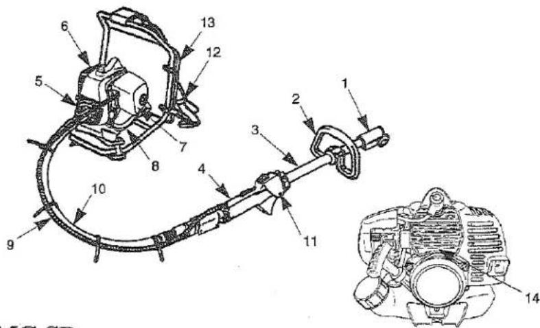
- Shaft connector
- Loop Handle
- Shaft Assembly
- Shaft Grip
- Clutch Drum Housing
- Engine
- Air Filter
- Fuel Tank
- Throttle Cable and Stop Switch Wires
- Flexible Shaft
-
Throttle Trigger and Stop Switch
-
Knap Sack Band
-
Pad
-
Serial Number (on rear of engine)
MC-SB
(Straight Shaft Attachment)
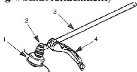
- Trimmer Head
- Gearcase
- Shaft Assembly
- Debris Shield
MC-E
(Edger Attachment)
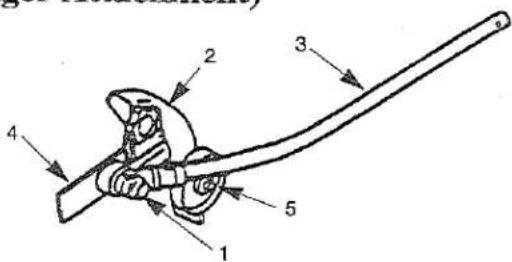
- Gearcase
- Debris Shield
- Shaft Assembly
- Edger Blade
- Wheel
MC-PS
(Pruner Attachment)
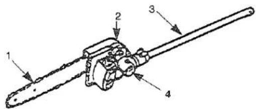
- Chain and Guide Bar
- Pruner Head
- Shaft Assembly
- Gearcase
MC-HT
(Hedge Trimmer Attachment)
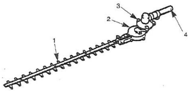
MC-T (Cultivator Attachment)
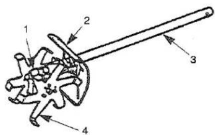
MC-HTS/MC-HTSL
(Swiveling Hedge Trimmer Attachment)
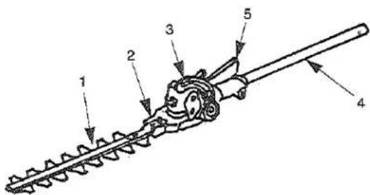
MC-HTR
(Swiveling Hedge Trimmer Attachment)
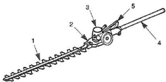
- Blades and GuideBar
- Gear case
- Angle Drive
-
Shaft Assembly
-
Gearcase
- Debris Shield
- Shaft Assembly
-
Cultivator Tines
-
Blades and Guide Bar
- Gear case
- Angle Drive
- Shaft Assembly
-
Handle
-
Blades and GuideBar
- Gear case
- Angle Drive
- Shaft Assembly
- Handle
Contents
Page US-
Limited Warranty Statement 1
Federal Emission Control 3
California Emission Control 5
Product Discription 6
Contents 8
Introduction 9
Safety 9
Operator Safety 9
Multi - Cutter with Tool Attachments Safety ..... 10
Fuel Safety 10
Multi - Cutter with Tool Attachments Operating Safety 11
Safety and Instruction Decals 14
Assembly 17
Installing Flexible Shaft 17
Loop Handle Installation 17
Connecting Stop Switch wires.... 17
Connecting Throttle Cable.... 18
Cable Adjustment 18
MC-SB (Straight Shaft Attachment) 19
Installing Debris Shield 19
Installing Trimmer Head.... 19
MC-E (Edger Attachment).... 20
Installing Debris Shield 20
Installing Edger Blade 20
MC-PS (Pruner Attachment) 20
Installing Shaft and Gearcase.... 20
Installing Guide Bar and Chain 21
MC-HTS/MC-HTSL/MC-HTR
(Hedge Trimmer Attachment).... 22
Installing Shaft and Gearcase 22
MC-T (Cultivator Attachment) 22
Installing Shaft and Shield 22
Connecting the Tool Attachments to the Power Unit... 23
Before Operation.... 23
Chain Oil (Multi - Cutter with Pruner Attachment).... 23
Oil and Fuel 24
Mixing Gasoline And Oil 25
Starting And Stopping 26
Idle Speed Adjustment.... 27
Page US-
Operation
MC-SB (Multi-Cutter with Straight Shaft 28
Attachment)
MC-E (Multi-Cutter with Edger Attachment)..... 30
MC-PS (Multi-Cutter with Pruner Attachment).. 31
MC-HT/MC-HTS/MC-HTSL/MC-HTR
(Multi-Cutter with HedgeTrimmer Attachment) ..... 32
MC-T (Multi-Cutter with Cultivator Attachment)... 34
Maintenance 35
Engine 35
Air Filter 35
Fuel Filter 35
Spark Plug.... 36
Cylinder Cooling Fins 36
Spark Arrester 37
Exhaust Muffler 38
Flexible Shaft 39
MC-SB (Straight Shaft Attachment) 39
Gearcase.... 39
MC-E (Edger Attachment).... 39
Flexible Driveshaft 39
MC-PS (Pruner Attachment) 40
MC-HT/MC-HTS/MC-HTSL/MC-HTR
(Hedge Trimmer Attachment) 40
Adjusting Cutting Blades.... 40
Lubrication.... 41
MC-T (Cultivator Attachment) 41
Lubrication.... 41
General Cleaning and Tightening 42
Storage.... 42
Troubleshooting 43
Maintenance Period.... 43
Specifications 44
Introduction
Thank you for purchasing a MARUYAMA product.
Maruyama, it's distributors, and dealers want you to be completely satisfied with your new product. Please feel free to contact your local Authorized Service Dealer for help with service, genuine Maruyama parts, or other information you may require.
Whenever you contact your Authorized Service Dealer or the factory, always know the serial number of your product. This number will help the Service Dealer or Service Representative provide exact information about your specific product. You will find the model and serial number located in a unique place on the product (Product Description on page US-6).
For your convenience, write the product model name and serial number in the space below.
Model Name
Serial No.
Read this manual carefully to learn how to operate and maintain your product correctly. Reading this manual will help you and others avoid personal injury and damage to the product. Although MARUYAMA designs, produces and markets safe, state of the art products, you are responsible for using the product properly and safely. You are also responsible for training persons who you allow to use the product about safe operation.
The MARUYAMA warning system in this manual identifies potential hazards and has special safety messages that help you and others avoid personal injury, even death.
DANGER, WARNING and CAUTION are signal words used to identify the level of hazard. However, regardless of the hazard, be extremely careful.
DANGER signals an extreme hazard that will cause serious injury or death if the recommended precautions are not followed.
WARNING signals a hazard that may cause serious injury or death if the recommended precautions are not followed.
CAUTION signals a hazard that may cause minor or moderate injury if the recommended precautions are not followed. Two other words are also used to highlight information. "Important" calls attention to special mechanical information and "Note" emphasizes general information worthy of special attention.
Safety
Operator Safety
-
Read and understand this Operator's Manual before using this product. Be thoroughly familiar with the proper use of this product.
-
Never allow children to operate the Trimmer/Brushcutter. It is not a toy. Never allow adults to operate the unit without first reading the Operator's Manual.
-
Always wear eye protection that complies with ANSI (American National Standards Institute) Z87-1.

- Always wear hearing protection.

-
Always wear heavy, long pants, a long sleeved shirt, boots and gloves. Do not wear loose clothing, jewelry, short pants, sandals, or go barefoot. Secure hair so it is above shoulder length.
-
Never operate this Multi-Cutter when you are tired, ill, or under the influence of alcohol, drugs or medication.
-
Never start or run the engine inside a closed room or building. Breathing exhaust fumes can cause death.

- Keep handles clean of oil, fuel and dirt.
Multi-Cutter with Tool Attachments Safety
-
Make sure the Unit is assembled correctly and that the tool attachment is correctly installed and securely fastened as instructed in the Assembly section.
-
Inspect the Unit before each use. Replace damaged parts. Check for fuel leaks. Make sure all fasteners are in place and tightened securely. Follow the maintenance inst-ructions beginning on page US-35.
-
Make sure the tool attachment does not rotate at engine idle speed. Refer to Idle Speed Adjustment, page US-27.
-
Inspect the tool attachment head and replace any parts that are cracked, chipped or damaged before using the Multi-Cutter.
-
Install all required shields and guards prior to operating the Multi-Cutter or its attachments. Note: Remove blade cover from Hedgetrimmer attach-ments prior to operation.
-
Never use a tool attachment head or replacement parts that are not approved by MARUYAMA.
-
Maintain the Multi-Cutter power unit and tool attach-ments according to the recommended maintenance intervals and procedures in the Maintenance section.
-
Shut off the engine and wait until the tool attachment head has completely stopped moving before checking, performing maintenance on or working on the Multi-Cutter.
-
If running problems or excessive vibration occur, stop immediately and inspect the unit for the cause. If the cause cannot be determined or is beyond your ability to correct, return the Multi-Cutter with tool attachment to your servicing dealer for repair.
Fuel Safety
- Gasoline is highly flammable and must be handled and stored carefully. Use a container approved for fuel to store gasoline and/or fuel/oil mixture.
- Mix and pour fuel outdoors, where there are no sparks or flames.
- Do not smoke near fuel or Multi-Cutter, or while using the Multi-Cutter.
- Do not overfill the fuel tank. Stop filling 1/4-1/2 inch (6 mm-13 mm) from the top of the tank.
- Wipe up any spilled fuel before starting the engine.
- Move the Multi-Cutter at least 10 feet (3 m) away from the fueling location before starting the engine.
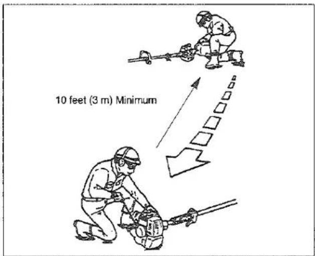
- Do not remove the fuel tank cap while the engine is running, or right after stopping the engine.
- Allow the engine to cool before refueling.
- Drain the tank and run the engine dry before storing the unit.
- Store fuel and Multi-Cutter away from open flame, sparks and excessive heat. Make sure fuel vapors cannot reach sparks or open flames from water heaters, furnaces, electric motors, etc.
Multi-Cutter with Tool Attachments Operating Safety
String Trimmer Operating Safety
- THIS STRING TRIMMER CAN CAUSE SERIOUS INJURIES. Read the instructions carefully. Be familiar with all controls and the proper use of the String Trimmer.
- Inspect your work area before you begin. Remove objects such as broken glass, nails, wire and rocks which can become dangerous projectiles if thrown by the Trimmer. Remove string, rope or similar materials which can become entangled in the trimmer head.
- This Trimmer will throw objects and cut. Keep children, bystanders and animals outside a 50 ft.(15m) radius from the operator and Trimmer. Beyond the 50 ft. (15 m) there still may be a risk of injury to bystanders from thrown objects. It is recommended that bystanders wear eye protection. A thrown object can ricochet.
- If you are approached while operating the Trimmer, stop the engine and trimmer head rotation.
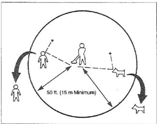
- Never allow children to operate the Trimmer.
- Use the Trimmer only in daylight or good artificial light.
-
Never operate the Trimmer without proper guards or other protective safety devices in place.
-
Use only flexible, non-metallic, monofilament cutting line of the correct diameter. Never use wire rope, string, etc.
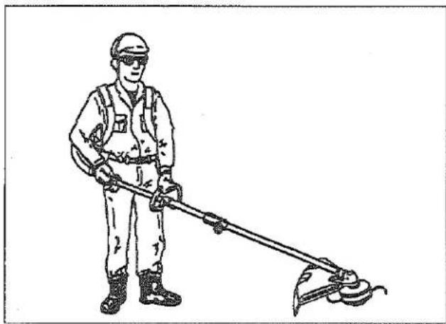
- Always keep the Trimmer on the right side of your body.
- Do not raise the trimmer head above waist level.
- Do not put hands or feet near or under any rotating parts. Keep clear at all times. Keep all parts of your body away from the rotating trimmer head and hot surfaces such as the muffler.
- Keep firm footing and balance. Do not overreach.
- Use the right tool for the job. Do not use the Trimmer for any job that is not recommended by MARUYAMA.
natural_image
Line drawing of a worker in safety gear using a handheld tool (no text or symbols)Edger Operating Safety
- THIS EDGER CAN CAUSE SERIOUS INJURIES. Read the instructions carefully. Be familiar with all controls and the proper use of the Edger.
- Make sure the 3 mm hex wrench has been removed from the gearcase and boss adapter before you start the engine.
- Inspect your work area before you begin. Remove objects such as broken glass, nails, wire and rocks which can become dangerous projectiles if thrown by the Edger. Remove string, rope or similar materials which can become entangled in the Edger head.
-
This Edger will throw objects and cut. Keep children, bystanders and animals outside a 50 ft. (15m) radius from the operator and Trimmer. Beyond the 50 ft. (15 m) there still may be a risk of injury to bystanders from thrown objects. It is recommended that bystanders wear eye protection. A thrown object can ricochet. (See the String Trimmer Operating Safety)
-
If you are approached while operating the Edger, stop the engine and Edger blade rotation.
-
Never allow children to operate the Edger.
-
Use the Edger only in daylight or good artificial light.
-
Never operate the Edger without proper guards or other protective safety devices in place.
-
Do not put hands or feet near or under any rotating parts. Keep clear at all times. Keep all parts of your body away from the rotating Edger blade and hot surfaces such as the muffler.
-
Keep firm footing and balance Do not overreach.
-
Use the right tool for the job. Do not use the Edger for any job that is not recommended by MARUYAMA.
Pruner Operating Safety
-
THIS PRUNER CAN CAUSE SERIOUS INJURIES. Read the instructions carefully. Be familiar with all controls and the proper use of the Pruner.
-
The Pruner is designed to cut wood and can therefore be potentially dangerous. Careless or improper use can cause serious or even fatal injury.
-
This Pruner can conduct electricity. Do not use where contact can be made with live electrical circuits. Never use around electrical power sources and lines. Failure to observe this warning can result in serious injury or death.
-
Beware of where material will fall after being cut. Do not stand underneath falling material.
-
Inspect your work area before you begin. Remove objects such as broken glass, nails, wire and rocks which can become dangerous projectiles if thrown by the Pruner. Remove string, rope or similar materials which can become entangled in the Pruner head.
-
This Pruner will throw objects and cut. Keep children, bystanders and animals outside a 50 ft. (15m) radius from the operator and Trimmer. Beyond the 50 ft. (15 m) there still may be a risk of injury to bystanders from thrown objects. It is recommended that bystanders wear eye protection. A thrown object can ricochet. (See the String Trimmer Operating Safety)
-
If you are approached while operating the Pruner, stop the engine and Pruner chain motion.
-
Use the Pruner only in daylight or good artificial light.
-
Do not put hands or feet near or under any rotating parts. Keep clear at all times. Keep all parts of your body away from the Pruner chain and hot surfaces such as the muffler.
-
Keep firm footing and balance. Do not overreach.
-
Use the right tool for the job. Do not use the Pruner for any job that is not recommended by MARUYAMA.
Hedge Trimmer Operating Safety
-
THIS HEDGE TRIMMER CAN CAUSE SERIOUS INJURIES. Read the instructions carefully. Be familiar with all controls and the proper use of the Hedge Trimmer.
-
The Hedge Trimmer is designed to trim foliage and small branches, and can therefore be potentially dangerous. Careless or improper use can cause serious injury.
-
Inspect your work area before you begin. Remove objects such as broken glass, nails, wire and rocks which can become dangerous projectiles if thrown by the Hedge Trimmer. Remove string, rope or similar materials which can become entangled in the Hedge trimmer cutter.
-
This Hedge Trimmer will throw objects and cut. Keep children, bystanders and animals outside a 50 ft. (15m) radius from the operator and Trimmer. Beyond the 50 ft. (15 m) there still may be a risk of injury to bystanders from thrown objects. It is recommended that bystanders wear eye protection. A thrown object can ricochet. (See the String Trimmer Operating Safety)
-
If you are approached while operating the Hedge Trimmer, stop the engine and cutting blades.
-
Never allow children to operate the Hedge Trimmer.
-
Use the Hedge Trimmer only in daylight or good artificial light.
-
Do not put hands or feet near or under any moving parts. Keep clear at all times. Keep all parts of your body away from the cutting blade and hot surfaces such as the muffler.
-
Keep firm footing and balance. Do not overreach.
-
Watch for wires. Keep sufficient distance away from electrical power lines.
-
Use the right tool for the job. Do not use the Hedge Trimmer for any job that is not recommended by MARUYAMA.
Cultivator Operating Safety
-
THIS CULTIVATOR CAN CAUSE SERIOUS INJURIES. Read the instructions carefully. Be familiar with all controls and the proper use of the Cultivator.
-
Avoid using the Cultivator near rocks, graval, stones and similar material that would cause harmful missiles.
-
Inspect your work area before you begin. Remove objects such as broken glass, nails, wire and rocks which can become dangerous projectiles if thrown by the Cultivator. Remove string, rope or similar materials which can become entangled in the Cultivator head.
-
This Cultivator will throw objects and cut. Keep children, bystanders and animals outside a 50 ft. (15m) radius from the operator and Trimmer. Beyond the 50 ft. (15 m) there still may be a risk of injury to bystanders from thrown objects. It is recommended that bystanders wear eye protection. A thrown object can ricochet. (See the String Trimmer Operating Safety)
-
If you are approached while operating the Cultivator, stop the engine and cultivate tool rotation.
-
Use the Cultivator only in daylight or good artificial light.
-
Do not put hands or feet near or under any rotating parts. Keep clear at all times. Keep all parts of your body away from the rotating tool and hot surfaces such as the muffler.
-
If the cultivator tines become jammed, stop the engine immediately. Make certain all moving parts have stopped, and disconnect the spark plug before attempting to remove any obstruction.
-
Use the right tool for the job. Do not use the Cultivator for any job that is not recommended by MARUYAMA.
Safety and Instruction Decals

Safety decals and instructions are easily visible to the operator and are located near any area of potential danger. Replace any decal that is damaged or lost.
MC - SB (Straight Shaft Attachment)

ON SHAFT (Part No.221501)

ON SHAFT (Part No.221502)
MC - E (Edger Attachment)

ON SHAFT
(Part No.221501)

ON SHAFT (Part No.221502)
Lubricate drive-shaft each 30 hours of use.
ON SHAFT (Part No.223926)

ON DEBRIS SHIELD (Part No.221528)
MC - PS (Pruner Attachment)

ON SHAFT
(Part No.221501)

ON SHAFT
(Part No.221529)

ON SHAFT
(Part No.219937)
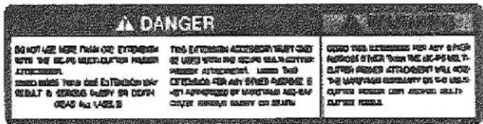
ON SHAFT
(Part No.220295)
MC - HT (Hedge Trimmer Attachment)
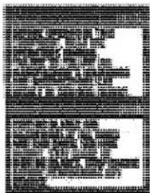
ON SHAFT
(Part No.217879)
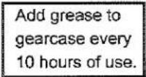
ON CEARCASE
(Part No.223925)
MC-T (Cultivator Attachment)

ON SHAFT
(Part No.221501)

ON SHAFT
(Part No.221502)
MC-HTS/MC-HTSL/MC-HTR (Hedge Trimmer Attachment)
Add grease to gearcase every 10 hours of use.
ON CEARCASE (Part No.223925)

ON SHAFT (Part No.221501)
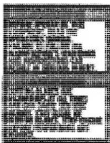
ON SHAFT (Part No.217879)

natural_image
Four circular icons with warning symbols: triangular warning triangle, person holding a phone, circuit board, and triangular warning triangle (no text or labels)ON GEARCASE [MC-HTS/ MC-HTSL] (Part No.631786) [MC-HTR] (Part No.407349)


Handling this machine improperly could result in accidents causing serious injury or death. Read this manual carefully and practice using the trimmer until you are fully acquainted with all operations and have learned to use it correctly.
Carefully read owner's manual.
Always be careful to wear a face protector, ear protector and helmet when using your Hedge Trimmer.
Keep hands away from cutting blades.
Assembly
Installing Flexible Shaft
- Remove the bolt and insert the outer fitting (with o-ring) into the joint pipe, and tighten the bolt.
- Insert the outer fitting into the clutch drum housing with pulling up the Pin. Be sure pin returns to original position by spring and outer fitting never comes off from clutch drum housing.
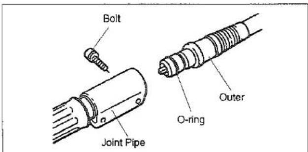
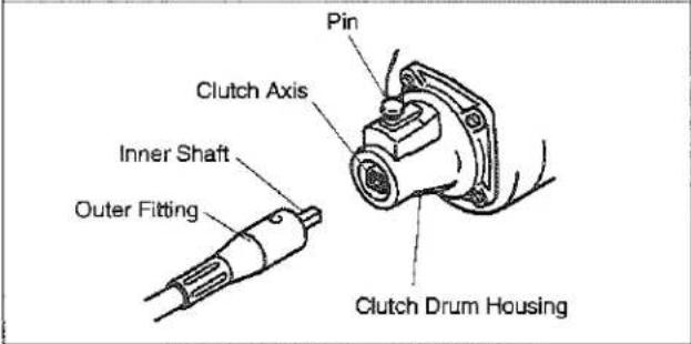
Loop Handle Installation
The loop handle kit contains a package of four screws and nuts and the bottom clamp for the loop handle.
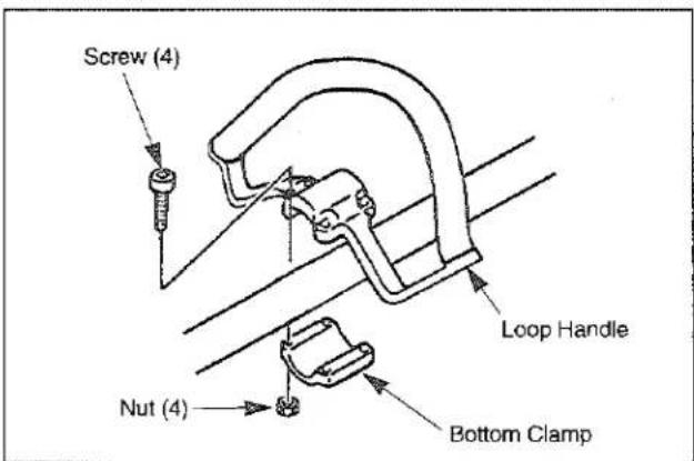
-
Place the loop handle and the bottom clamp on the shaft approximately 28cm(11 inches) from the end of the stop switch/throttle trigger assembly.
-
Install the four screws and nuts. Leave the screws fingertight.
- Reposition the loop handle up or down the drive-shaft to the most comfortable position, but no closer than 9 inches (22.8 cm) from the end of the stop switch.
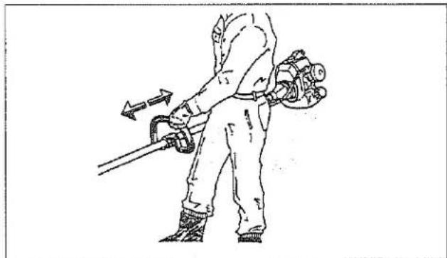
natural_image
Line drawing of a person in protective gear using a tool, with arrows indicating motion direction (no text or symbols)- Tighten the screws and nuts.
Connecting Stop Switch Wires
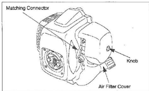
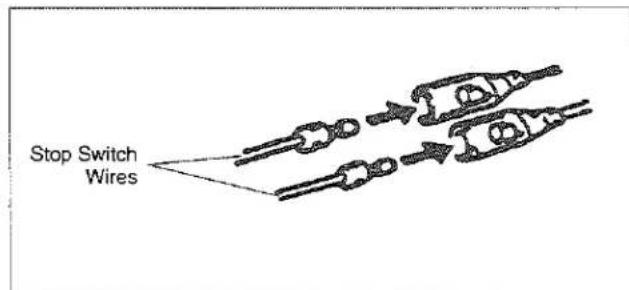
Plug the stop switch wires into the matching connectors from the engine. Note that wire polarity is not important.
Connecting Throttle Cable
- Loosen the knob and remove the air cleaner cover, insert the throttle cable through the cable adjuster sleeve on the carburetor bracket. Make sure the end of the cable housing is seated positively in the sleeve.
- Position the slotted fitting on the carburetor so the recessed hole for the cable lug is away from the cable adjuster sleeve.
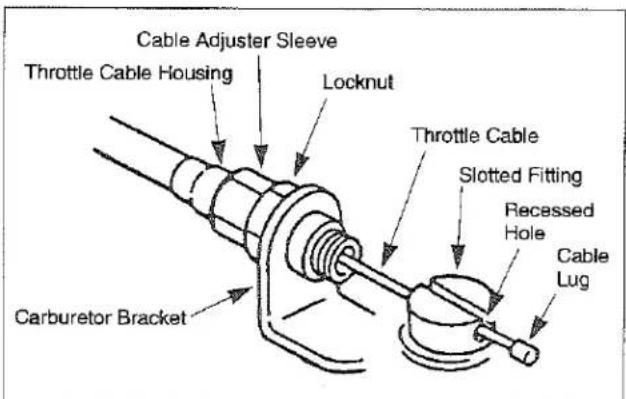
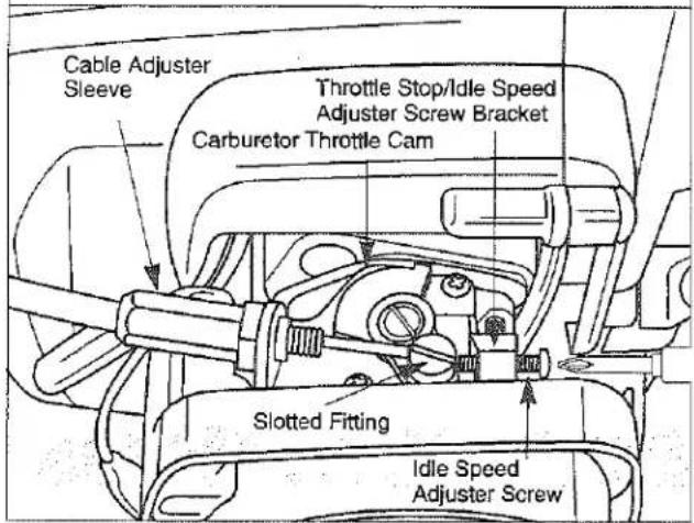
- Rotate the carburetor throttle cam clockwise and slip the throttle cable through the slot in the slotted fitting, making sure the cable lug drops into the recessed hole.
-
Operate the throttle trigger a few times to make sure that it works correctly.
-
Bind the throttle cable and the flexible shaft with four bands.
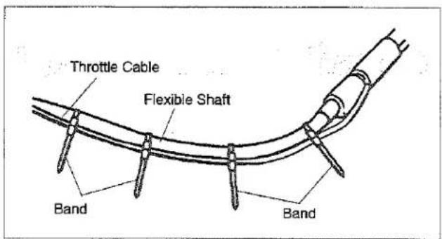
Cable Adjustment
- Throttle cable should be paralleled to flexible shaft. In case of twisting, they should be restored by parallel.
-
Throttle cable should be adjusted under the bended flexible shaft as shown.
-
Adjust the cable adjuster sleeve so the stop on the carburetor throttle cam just contacts the throttle stop and the cable position keep 1-2mm play between cable lug and slotted fittings when the throttle trigger is fully depressed.
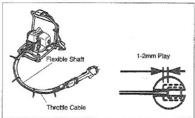
- When the throttle cable is adjusted correctly, tighten the lock nut.
MC-SB (Straight Shaft Attachment)
Installing the Debris Shield
WARNING
POTENTIAL HAZARD
- Foreign objects can be thrown by the String Trimmer.
WHAT CAN HAPPEN
* Contact with thrown objects can cause personal injury.
HOW TO AVOID THE HAZARD
- Never operate the String Trimmer without the debris shield in place.
CAUTION
POTENTIAL HAZARD
• The String cutoff blade is sharp.
WHAT CAN HAPPEN
- Contact with cutoff blade can cause serious cuts or personal injury.
HOW TO AVOID THE HAZARD
- Keep hands, feet and clothing away from cutoff blade.
- Fasten the string cutoff blade to the debris shield with two M5 x 12 screws and hex nuts.
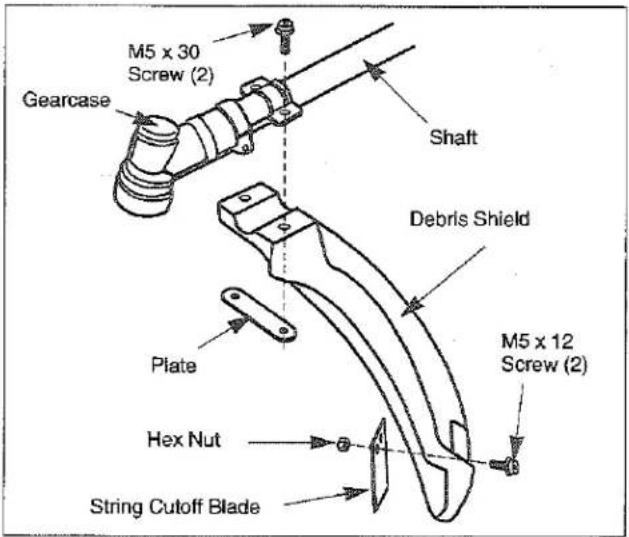
- Attach the debris shield to the gearcase with the two M5 x 30 screws and plate as shown.
Installing Trimmer Head
IMPORTANT: The boss adapter must be, installed on the attaching shaft between the gearcase and the trimmer head as shown. And Trimmer head adapter is left-head.
- Install the boss adapter onto the attaching shaft out of the gearcase.
- Align the hole in the boss adapter with the hole in the gearcase.
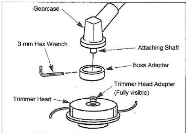
- Insert the 3 mm hex wrench into the holes in the boss adapter and gearcase to lock the attaching shaft.
- Thread the trimmer head adapter into the attaching shaft, then tighten the trimmer head firmly by hand.
CAUTION
POTENTIAL HAZARD
• If the Trimmer Head is not adequately tightened, it can come loose from the String Trimmer during use.
WHAT CAN HAPPEN
• This may cause damage to property or personal injury.
HOW TO AVOID THE HAZARD
• Make sure the trimmer head is securely fastened to the attaching shaft in the gearcase.
MC-E (Edger Attachment)
Installing Debris Shield
WARNING
POTENTIAL HAZARD
• Foreign objects can be thrown by the Edger.
WHAT CAN HAPPEN
- Contact with thrown objects can cause personal injury.
HOW TO AVOID THE HAZARD
• Never operate the Edger without the debris shield in place.
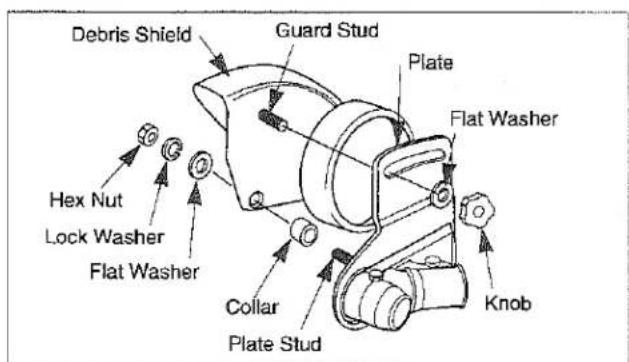
- Install the collar onto the plate stud.
- Install the shield onto the plate stud, making sure the shield stud fits into the matching slot in the plate.
- Install the flat washer, lock washer and hex nut onto the plate stud.
- Install the flat washer and knob onto the shield stud.
Installing Edger Blade
CAUTION
POTENTIAL HAZARD
- If the Edger blade is not adequately tightened, it can come loose from the Edger during use.
WHAT CAN HAPPEN
• This may cause damage to property or personal injury.
HOW TO AVOID THE HAZARD
• Make sure the Edger blade is securely fastened to the attaching shaft in the gearcase.
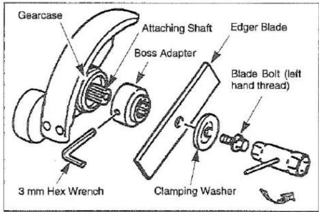
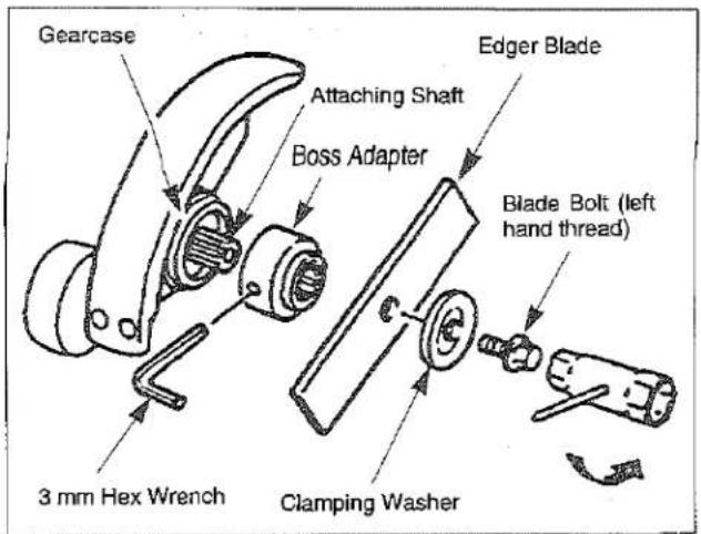
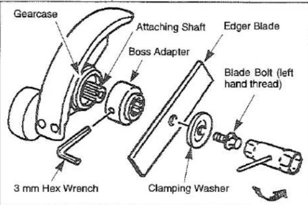
- Install the boss adapter onto the splined shaft out of the gearcase.
- Install the edger blade, clamping washer and blade bolt.
Note: The blade bolt has left-hand threads.
- Align the hole in the boss adapter with the hole in the gearcase.
- Insert the 3 mm hex wrench into the holes in the boss adapter and gearcase to lock the splined shaft.
- Tighten the blade bolt to 100 in.-lbs. (11.3 N·m).
- Remove the 3 mm hex wrench from the boss adapter and gearcase.
MC-PS (Pruner Attachment)
Installing Shaft and Gearcase
Attach the driveshaft tube assembly to the gearcase assembly.
NOTE: Carefully inspect both ends of the driveshaft protruding from the driveshaft tube. The squared end of the driveshaft positions toward the connector of the power unit. The splined end of the driveshaft connects to the gearcase assembly.
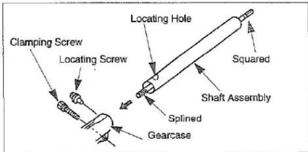
Insert the driveshaft tube assembly into the gearcase assembly whilerotating the driveshaft to engage the splines. Align the locating holes and install the locating screw through the side of the gearcase. Then tighten the clamping screws. If properly installed, rotating the square end of the driveshaft will cause the Rim sprocket to turn.
Installing Guide Bar and Chain
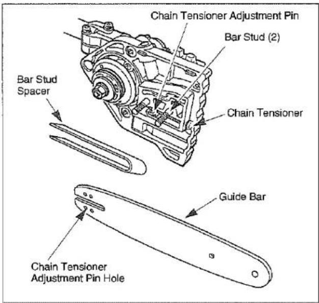
- Remove the nuts from the two bar studs.
- Fit the guide bar over the two bar studs.
If you are using the 11-inch Prolite bar, make sure the bar stud spacer is installed over the bar studs, and is completely against the bar mount. Place the bar in its rearmost position.
Do not engage the chain tensioner adjustment pin in the chain tensioner adjustment pin hole at this time.
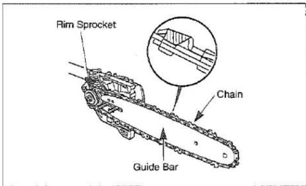
- Place the chain over the rim sprocket and into the groove on the guide bar. Make sure the cutting teeth edges are facing forward on the top side of the guide bar.
CAUTION
• Always wear gloves when handling the Pruner chain.
- Pull the guide bar forward until the chain tensioner adjustment pin hole is positioned over the chain tensioner adjustment pin. If necessary, turn the chain tensioner screw in the appropriate direction to align the pin with the hole. Check that the drive links on the chain fit correctly into the rim sprocket and guide bar groove.
- Install the sprocket cover onto the two bar studs. Install the bar stud nuts, but leave the nuts finger-tight).
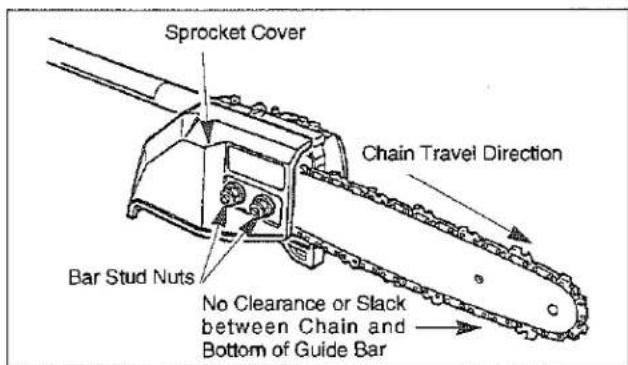
- Rotate the chain tensioner screw until all slack is removed between the chain and the bottom of the guide bar, but loose enough to allow you to pull the chain around the guide bar by hand.
- Tighten the bar stud nuts and recheck the chain tension.
IMPORTANT: When using a new chain, you must check the chain tension frequently and adjust the tension as necessary until the chain breaks in. A correctly adjusted chain gives optimum cutting performance and prevents premature wear to both the chain and guide bar.
MC-HTS/MC-HTSL/MC-HTR (Hedge Trimmer Attachment)
Installing Shaft and Gearcase
Attach the driveshaft tube assembly to the gearcase assembly.
NOTE: Carefully inspect both ends of the driveshaft protruding from the driveshaft tube. The squared end of the driveshaft positions toward the connector of the power unit. The splined end of the driveshaft connects to the gearcase assembly.
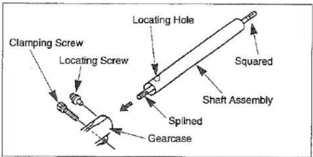
Insert the driveshaft tube assembly into the gearcase assembly whilerotating the driveshaft to engage the splines. Align the locating holes and install the locating screw through the side of the gearcase. Then tighten the clamping screws. If properly installed, rotating the square end of the driveshaft will cause the trimmer baldes to move.
MC-T (Cultivator Attachment)
Installing Shaft and Shield
- Attach the driveshaft tube assembly to the gearcase assembly.
NOTE: Carefully inspect both ends of the driveshaft protruding from the driveshaft tube. The squared end of the driveshaft positions toward the connector of the power unit. The splined end of the driveshaft connects to the gearcase assembly.
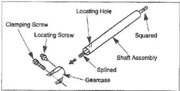
Insert the driveshaft tube assembly into the gearcase assembly whilerotating the driveshaft to engage the splines. Align the locating holes and install the locating screw through the side of the gearcase. Then tighten the clamping screws. If properly installed, rotating the square end of the driveshaft will cause the cultivator tines to move.
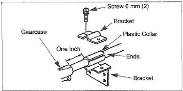
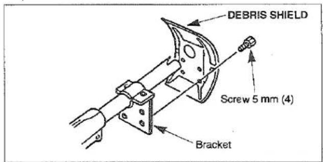
- Attach the debris shield onto the driveshaft tube assembly.
Place the plastic collar onto the driveshaft tube approximately one inch from the cultivator gearcase, locating the ends as shown in sketch. Then place the two bracket parts onto the plastic collar and fasten securely with two 6 mm screws. Attach the shield to the bracket with four 5 mm screws.
Connecting the Tool Attachments to the Power Unit
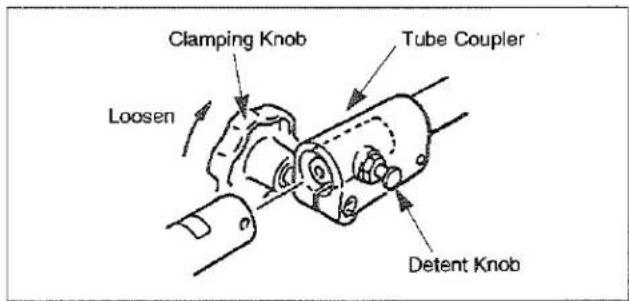
First, loosen the clamping knob so the shaft of the tool attachment can be inserted into the tube coupler. Pull the detent knob outward and gently rotate the attachment shaft back and forth while inserting to be sure the drive-
shafts completely in place. The spring-loaded detent knob will snap into place when the attachment shaft is correctly positioned. Tighten the clamping knob. When changing the tool attachment be careful not to overloosen the clamping knob to prevent it from falling.
Before Operation
Chain Oil (Multi-Cutter with Pruner Attachment)
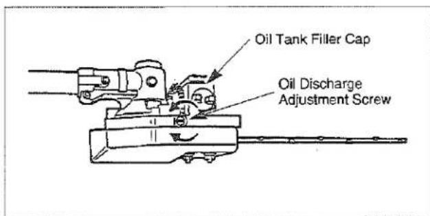
The chain and guide bar are lubricated by a centrifugal pump. The oil discharge rate is controlled by the oil discharge adjustment screw on the top of the pruner head.
Remove the oil tank filler cap fill the tank, then replace the cap.
IMPORTANT: Only use oil designed for lubricating chain saw chains and guide bars. Do not use waste oil. Never run the chain dry. In temperatures below freezing, check the chain oil viscosity (pour point). If the oil is not rated for use below freezing, it may not provide adequate lubrication, resulting in damage to the oil pump, chain and guide bar.
IMPORTANT: When filling the oil tank for the first time, or when the tank is completely empty, wait approximately 60-90 seconds before starting the Pruner. This will give the oil time to flow from the tank to the pump. Otherwise, an air lock can occur which will prevent oil from moving through the pump. This will result in damage to the chain and guide bar.
Oil and Fuel
! DANGER
POTENTIAL HAZARD
• In certain conditions gasoline is extremely flammable and highly explosive.
WHAT CAN HAPPEN
• A fire or explosion from gasoline can burn you, others and cause property damage.
HOW TO AVOID THE HAZARD
• Use a funnel and fill the fuel tank outdoors, in an open area, when the engine is cold. Wipe up any gasoline that spills.
- Do not fill the fuel tank completely full. Add gasoline to the fuel tank until the level is 1/4" to 1/2" (6 mm to 13mm) below the bottom of the filler neck. This empty space in the tank allows gasoline to expand.
• Never smoke when handling gasoline, and stay away from an open flame or where gasoline fume may be ignited by a spark.
- Store gasoline in an approved container and keep it out of the reach of children.
- Never buy more than a 30-day supply of gasoline.
- Do not smoke near fuel.
- Mix and pour fuel outdoors and where there are no sparks or flames.
WARNING
POTENTIAL HAZARD
• Gasoline contains gasses that can build up pressure inside a gas tank.
WHAT CAN HAPPEN
• Fuel can be sprayed on you when removing gas cap.
HOW TO AVOID THE HAZARD
- Remove fuel cap slowly to avoid injury from fuel spray.
- Always shut off the engine before refueling.
Never remove the fuel tank cap while the engine is running or right after just stopping the engine.
- Always open the fuel tank cap slowly to release any possible overpressure inside the tank.
- Do not overfill the fuel tank. Stop filling 1/4-1/2 inch (6 mm-13 mm) from the top of the tank.
- Tighten the tank fuel cap carefully but firmly after refilling.
- Wipe up any spilled fuel before starting the engine.
- Move the unit at least 10 feet (3 m) away from the fueling location and fuel storage container before starting the engine.
Recommended Oil Type
Only use a two-cycle engine oil formulated for use in high performance, air cooled two cycle engines.
MARUYAMA brand 2-cycle oil is formulated for use in high performance, air cooled two-cycle engines.
IMPORTANT: Do not use National Marine Manufacturer's Association (NMMA) or BIA certified oils. This type of 2-cycle engine oil does not have the proper additives for air cooled, 2-cycle engines and can cause engine damage.
Do not use automotive motor oil. This type of oil does not have the proper additives for air cooled, 2-cycle engines and can cause engine damage.
Recommended Fuel Type
Use clean, fresh lead-free gasoline, including oxygenated or reformulated gasoline, with an octane rating of 89 or higher. To ensure freshness, purchase only the quantity of gasoline that can be used in 30 days. Use of lead-free gasoline results in fewer combustion chamber deposits and longer spark plug life. Use of premium grade fuel is not necessary or recommended.
Use Of Fuel Additives
IMPORTANT: NEVER USE ALCOHOL, GASOHOL CONTAINING MORE THAN 10% ALCOHOL BECAUSE ENGINE FUEL SYSTEM DAMAGE COULD RESULT.
DO NOT USE FUEL ADDITIVES OTHER THAN THOSE MANUFACTURED FOR FUEL STABILIZATION DURING STORAGE SUCH AS MARUYAMA'S STABILIZER/ CONDITIONER OR A SIMILAR PRODUCT. MARUYAMA'S STABILIZER/CONDITIONER IS A PETROLEUM DISTILLATE BASED CONDITIONER/STABILIZER.
MARUYAMA DOES NOT RECOMMEND STABILIZERS WITH AN ALCOHOL BASE SUCH AS ETHANOL, METHANOL OR ISO-PROPYL. ADDITIVES SHOULD NOT BE USED TO TRY TO ENHANCE THE POWER OR PERFORMANCE OF MACHINE.
Mixing Gasoline And Oil
IMPORTANT: The engine used on this MultiCutter is of a 2-cycle design. The internal moving parts of the engine, i.e., crankshaft bearings, piston pin bearings and piston to cylinder wall contact surfaces, require oil mixed with the gasoline for lubrication.
Failure to add oil to the gasoline or failure to mix oil with the gasoline at the appropriate ratio will cause major engine damage which will void your warranty.
For your fuel premix, use Maruyama Premium 2-cycle Oil Mix, or equivalent ISO-L-EGD & JASO FD oil with a minimum 89 octane high Quality gasoline. Maruyama 2-cycle oil is specially formulated to meet the requirements of high-performance, low-emission air-cooled 2-cycle engines. Use of other oils may lead to service issues which may Not be covered by your warranty.
Fuel Mixture
The fuel: oil ratio is 50 parts gasoline to 1 part oil or 50:1.
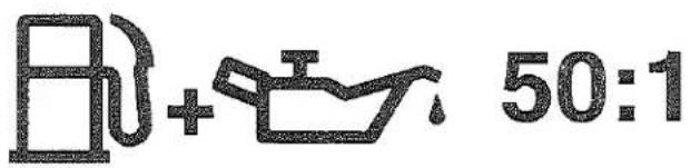
Note: Never use a mixing ratio less than 50:1 regardless of the oil package mixing instructions. Ratios less than 50:1, (for example, 60:1, 80:1, 100:1), reduce the amount of lubrication to the internal moving parts of the engine and can cause damage.
Fuel Mixture Chart
| Gasoline | 50:1 2-cycle oil |
| 1 gallon | 2.6 oz. |
| 2 gallons | 5.1 oz. |
| 5 gallons | 12.8 oz. |
| 1 litre | 20 ml |
| 5 litre | 100 ml |
Mixing Instructions
IMPORTANT: Never mix gasoline and oil directly in the Multi - Cutter fuel tank.
-
Always mix fuel and oil in a clean container approved for gasoline.
-
Mark the container to identify it as fuel mix for the Multi - Cutter.
-
Use regular unleaded gasoline and fill the container with half the required amount of gasoline.
-
Pour the correct amount of oil into the container then add the remaining amount of gasoline.
-
Close the container tightly and shake it momentarily to evenly mix the oil and the gasoline before filling the fuel tank on the Multi - Cutter.
-
When refilling the Multi - Cutter fuel tank, clean around the fuel tank cap to prevent dirt and debris from entering the tank during cap removal.
-
Always shake the premix fuel container momentarily before filling the fuel tank.
-
Always use a spout or funnel when fueling to reduce fuel spillage.
-
Fill the tank only to within 1/4-1/2 inch (6 mm-13 mm) from the top of the tank. Avoid filling to the top of the tank filler neck.
Starting And Stopping
Before Starting The Engine
- Fill the fuel tank as instructed in the Before Operation section of this manual (page US-23).
- Rest the Multi-Cutter on the ground.
- Make sure the cutting attachment is clear of any broken glass, nails, wire, rocks or other debris.
- Keep all bystanders, children and animals away from the working area.
Cold Starting Procedure
This Multi-Cutter is equipped with a fuel primer and a choke system. To start a "cold" engine properly, perform the following procedure:
- Pump the primer bulb at the bottom of the carburetor until fuel can be seen flowing through the fuel return line to the fuel tank. (Flowing fuel should be almost clear, not foamy or full of bubbles.)
[M30BK-S]
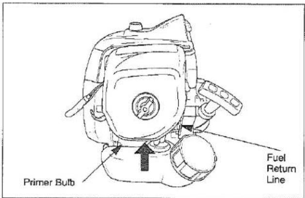
[M42BK]
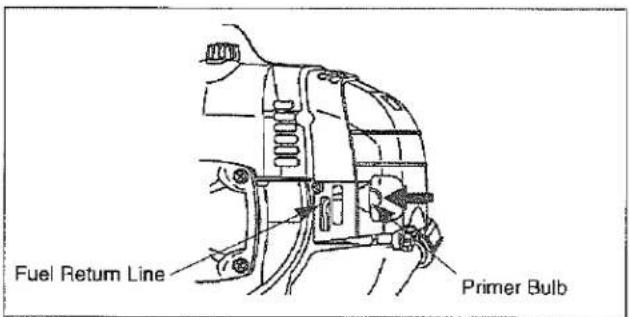
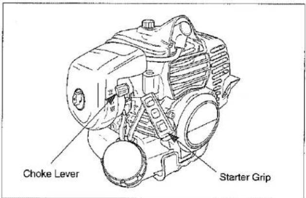
- Move the choke lever to the closed ( | | ) position and move the stop switch to the "ON" position.
[M30BK-S]
[M42BK]
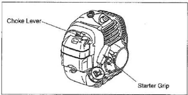
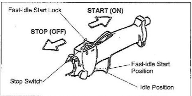
- Lock the throttle trigger in the fast-idle start position, then pull the starter grip.
CAUTION
^6 Do not pull the Starter rope all the way-out.
WARNING
• Do not disassemble the Starter. Please ask for an authorized MARYAMA service dealer.
- After the engine starts, squeeze and release the throttle trigger to return it to the idle position, then move the choke lever to the open ( |-| ) position.
If the engine stops running before you move the choke lever to the open (|→|) position:
A. Go ahead and open the choke.
B. Make sure the throttle trigger is set to the idle position.
C. Pull the starter grip until the engine starts.
Hot Restart
To start an engine that is already warmed up (hot restart), or if the ambient temperature exceeds 68°F (20°C):
-
Pump the primer bulb at the bottom of the carburetor until fuel can be seen flowing through the fuel return line to the fuel tank.
-
Move the choke lever to the open (|—|) position and move the stop switch to the "ON" position.
-
Leave the throttle trigger in the idle position and pull the starter grip.
-
If the engine fails to start after three to four pulls, follow the instruction in the Cold Starting Procedure section (page US-26).
If the engine fails to start after you follow the above procedures, contact an authorized Maruyama dealer.
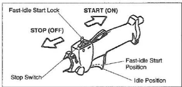
To Stop The Engine
- Release the throttle trigger.
- Slide the stop switch to the "STOP" position.
Idle Speed Adjustment
This Multi-Cutter is equipped with non-adjustable fuel mixture carburetor. The engine idle speed is the only adjustment for the operator.
WARNING
POTENTIAL HAZARD
• Engine must be running to make carburetor adjustments.
- When engine is running, attached tool and other parts is rotating / moving and other parts are moving.
WHAT CAN HAPPEN
- Contact with rotating / moving tool or other moving parts could cause serious personal injury or death.
HOW TO AVOID THE HAZARD
- Keep hands, feet and clothing away from attached tool and other moving parts.
- Keep all bystanders and pets away from unit while making carburetor adjustments.
The Attached Tool may be rotating/ moving during idle speed adjustment. Wear the recommended personal protective equipment and observe all safety instructions.
Keep hands and body away from the Attached Tool.
When the throttle trigger is released, the engine should return to an idle speed between 2700 and 3300 RPM, or just below the clutch engagement speed. The Attached Tool must not rotate/move and the engine should not stall (stop running) at engine idle speed.
To adjust the engine idle speed, rotate the idle speed adjustment screw on the carburetor.
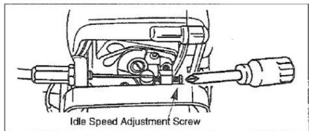
- Turn the idle speed screw in (clockwise) to increase the engine idle speed.
- Turn the screw out (counterclockwise) to decrease the engine idle speed.
If idle speed adjustment is necessary, and after adjustment the Attached Tool rotates/moves or the engine stalls, stop using the Multi-Cutter immediately!
Contact your local authorized MARUYAMA Dealer for assistance and servicing.
Operation
MC-SB (Multi-Cutter with Straight Shaft Attachment)

WARNING
POTENTIAL HAZARD
- Foreign objects can be thrown by String Trimmer.
WHAT CAN HAPPEN
- Contact with thrown objects can cause personal injury.
HOW TO AVOID THE HAZARD
- Never operate the String Trimmer without the debris shield.

CAUTION
- Read the Safety instructions on page US-10 concerning proper use of the String Trimmer.
Operating Position
Before using the Trimmer, check the following.
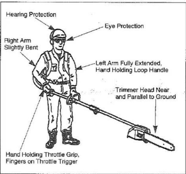
-
Make sure the Holding Tool (3 mm hex wrench) has been removed from the gearcase and boss adapter before you start the engine.
-
The operator must be set the Knapsack belt, and the shaft assembly must be on the operator's right side.
-
The operator's right hand should be holding the shaft grip, with his or her fingers on the throttle trigger.
- The left hand should be holding the loop handle with the fingers and thumb fully enclosed around the grip. The left arm should be extended.
Reposition the loop handle up or down the drive-shaft if necessary for a comfortable position.
- The Trimmer weight should be evenly distributed between the arms. The trimmer head should be near and parallel to the ground.
- Accelerate and hold the engine at cutting speed before entering the material to be cut.
- Always release the throttle trigger and allow the engine to return to idle speed when not cutting.
- Stop the Multi-Cutter engine when moving between work sites.

CAUTION
• Always wear gloves and protective clothing when operating the String Trimmer.
- If the trimmer head becomes jammed, stop the engine immediately.
- Make certain all moving parts have stopped and disconnect the spark plug before inspecting the equipment for damage.
- Never use a String Trimmer that has chipped, cracked or broken trimmer head.
Cutting with Trimmer Head
- The tip of the line does the cutting. The line should stay extended while cutting.
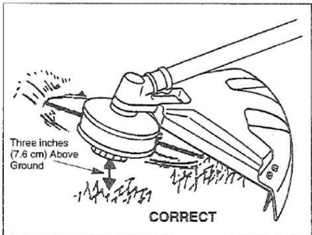
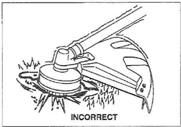
- Do not force the line into the material. Forcing the line will cause it to slap against the material, increasing line usage and causing poor cutting results.
Trimming
Hold the bottom of the trimmer head about 3 in. (7.6 cm) above the ground and at an angle. Allow only the tip of the line to make contact.
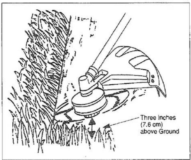
Scaling
To remove unwanted vegetation, hold the trimmer head about 3 in. (7.6 cm) above the ground and at an angle. Allow the tip of the line to strike the ground cutting the vegetation off at the surface.
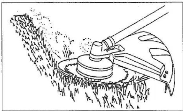
Mowing
Keep the line parallel to the ground and use a gentle side to side motion.
natural_image
Line drawing of a manual lawn saw cutting through grass, no text or symbols present
WARNING
POTENTIAL HAZARD
- Use of improper line could cause line to break and be thrown in operator's or bystander's direction.
WHAT CAN HAPPEN
• Use of improper line could result in serious personal injury.
HOW TO AVOID THE HAZARD
• Use only good quality, commercial grade, weld resistant trimmer line with a diameter of .095 inches (2.413 mm).
- Do not use any type of wire or other string-like substance. Do not use metalreinforced line.
MC-E (Multi-Cutter with Edger Attachment)

WARNING
POTENTIAL HAZARD
• Foreign objects can be thrown by Edger.
WHAT CAN HAPPEN
- Contact with thrown objects can cause personal injury.
HOW TO AVOID THE HAZARD
• Never operate the Edger without the blade shield in place.
• Make sure the blade shield is correctly positioned to shield operator from thrown debris.

CAUTION
- Read the Safety instructions on page US-14 concerning proper use of the Edger.
Operating Position
Before using the Edger, check the following:
- Make sure the 3 mm hex wrench has been removed from the gearcase and boss adapter before you start the engine.
- The operator must be set the Knapsack belt, and the shaft assembly must be on the operator's right side.
-
The operator's right hand should be holding the shaft grip, with his or her fingers on the throttle trigger. The right arm should be slightly bent.
-
The left hand should be holding the loop handle with the fingers and thumb fully enclosed around the grip. The left arm should be extended. Reposition the loop handle up or down the driveshaft if necessary for a comfortable position.
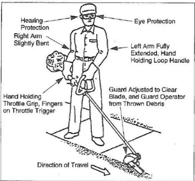
- The Edger weight should be evenly distributed between the arms.
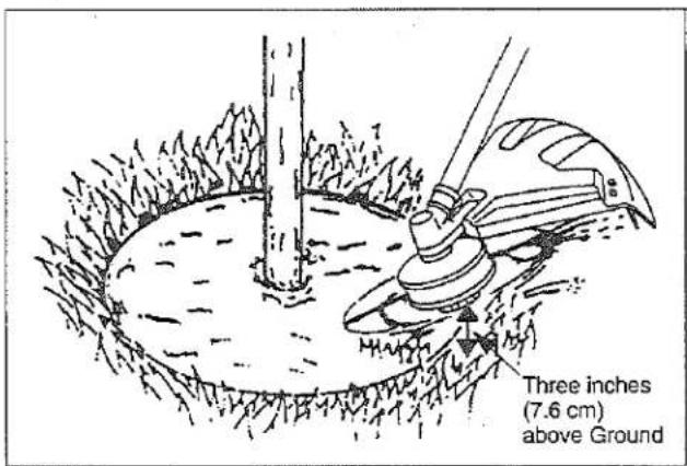
- Adjust the Edger to the correct cutting depth before you start the engine. (Refer to the figure below.) Make sure the shield is adjusted to shield the operator from thrown debris.
- Make sure the blade is rotating (at least half throttle) before inserting the blade into the cut. The Edger performs best at full throttle.
- Always release the throttle trigger and allow the engine to return to idle speed when not cutting.
- Stop the engine when moving between work sites.

CAUTION
• Always wear gloves and protective clothing when operating the Edger.
- If the Edger blade becomes jammed, stop the engine immediately.
• Make certain all moving parts have stopped and disconnect the spark plug before inspecting the equipment for damage. - Never use a Edger that has chipped, cracked or broken Edger blade or blade shield.
Setting Depth of Cut
IMPORTANT: Set the depth of cut before you start the engine.
- Loosen the knob holding the shield to the plate.
- Rotate the shield as necessary to set the depth of cut. Note that:
- Rotating the shield to raise the wheel increases the depth of cut.
- Rotating the shield to lower the wheel decreases the depth of cut.
- Make sure the shield is positioned to protect the operator from thrown debris, then tighten the knob.
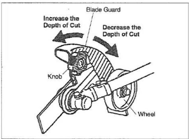
MC-PS (Multi-Cutter with Pruner Attachment)
WARNING
POTENTIAL HAZARD
• The Pruner can conduct electricity.
- Contact with live electrical wires or circuits can cause serious injury or death.
WHAT CAN HAPPEN
HOW TO AVOID THE HAZARD
- Never use the Pruner around electrical lines, circuits or components.
CAUTION
- Read the Safety instructions on page US-11 concerning proper use of the Pruner.
Before using the Pruner, check the following:
- Make sure the chain oil tank on the pruner head is full.
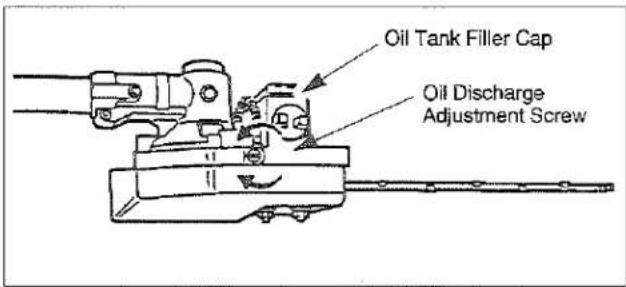
IMPORTANT: When filling an empty oil tank, wait approximately 60-90 seconds before starting the Pruner. This will give the oil time to flow from the tank to the pump. Otherwise, an air lock can occur which will prevent oil from moving through the pump. This will result in damage to the chain and guide bar.
IMPORTANT: Never run the chain dry.
- The operator must be set the Knapsack belt, and the shaft assembly must be on the operator's right side.
-
The operator's right hand should be holding the shaft grip, with his or her fingers on the throttle trigger. The right arm should be slightly bent.
-
The left hand should be holding the loop handle with the fingers and thumb fully enclosed around the grip. The left arm should be extended. Reposition the loop handle up or down the drive-shaft if necessary for a comfortable position.
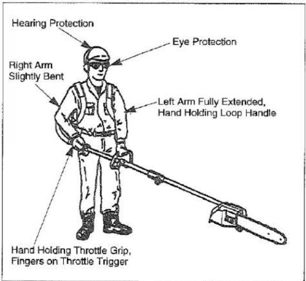
- The Pruner weight should be evenly distributed between the arms.
- Always release the throttle trigger and allow the engine to return to idle speed when not cutting.
- Stop the engine when moving between work sites.
CAUTION
• Always wear gloves and protective clothing when operating the Pruner.
- If the Pruner chain becomes jammed, stop the engine immediately.
- Make certain all moving parts have stopped and disconnect the spark plug before in-specting the equipment for damage.
- Never use a Pruner that has a damaged chain or guide bar.
MC-HT/MC-HTS/MC-HTSL/MC-HTR (Multi-Cutter with Hedge Trimmer Attachment)
CAUTION
- Read the Safety instructions on page US-12 concerning proper use of the Hedge Trimmer.
Operating Position
Before using the Hedge Trimmer, check the following.
- The operator must be set the Knapsack belt, and the shaft assembly must be on the operator's right side.
- The operator's right hand should be holding the shaft grip, with his or her fingers on the throttle trigger. The right arm should be slightly bent.
- The left hand should be holding the loop handle with the fingers and thumb fully enclosed around the grip. The left arm should be extended. Reposition the loop handle up or down the drive-shaft if necessary for a comfortable position.
- The Hedge Trimmer weight should be evenly distributed between the arms.
CAUTION
• Do not touch the sharpened edges of the cutting blades. The cutting blades are extremely sharp and dangerous at all times. Always wear gloves to help protect your hands and fingers from injury.
- Make sure the blades are moving (at least half throttle) before actual cutting begins. The HedgeTrimmer performs best at full throttle.
- Always release the throttle trigger and allow the engine to return to idle speed when not cutting.
- Stop the engine when moving between work sites.
CAUTION
- The thickness of branches which may be cut using this trimmer is limited to up to approximately 3/16". Never try to cut branches thicker than this, as doing so may result in damage to the trimmer.
- If the cutting blades becomes jammed, stop the engine immediately.
• Make certain all moving parts have stopped and disconnect the spark plug before inspecting the equipment for damage. - Never use a Hedge Trimmer that has chipped, cracked or broken Blades.
Adjusting the angle of the blades (MC-HTS/MC-HTSL)
CAUTION
• Do not touch the sharpened edges of the cutting blades. The cutting blades are extremely sharp and dangerous at all times. Always wear gloves to help protect your hands and fingers from injury.
• Do not hold any part other than the handle when adjusting the angle of the blades.
- Stop the engine when adjusting the angle of the blades.
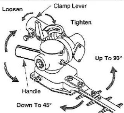
- Turn the clamp lever and loosen the clamp bolt. The clamp lever is designed to turn freely for your desired position. Lift and turn down the lever for your desired position. The lever should be fixed at the desired position.
- Always hold the handle when you adjust the angle of the blades. The blades are able to adjust the angle from 90 degree upwards to 45 degree downwards.
- After adjusting the angle, tighten the clamp lever firmly and fix the gearcase.
Adjusting the angle of the blades (MC-HTR)
CAUTION
- Do not touch the sharpened edges of the cutting blades. The cutting blades are extremely sharp and dangerous at all times. Always wear gloves to help protect your hands and fingers from injury.
- Do not hold any part other than the handle when adjusting the angle of the blades.
- Stop the engine when adjusting the angle of the blades.
Note: Never use the unit if the blade angle is not 48 degrees upwards to 84 degrees downward.
- First stop the engine. Next attach the blade cover.
- Turn the clamp knob counter clock wise until the clamp knob stops. Angle adjustments are not possible without completely loosening the clamp knob.
- Always hold the handle when adjusting the blades. The blades adjust from a 48 degree upward angle to an 84 degree downward angle. Never push the lock lever when adjusting the angle of the blades.
- After you have adjusted the angle of the blades tighten the clamp knob firmly and fix the gearcase in place. When tightening the clamp knob, make sure both racks engage.
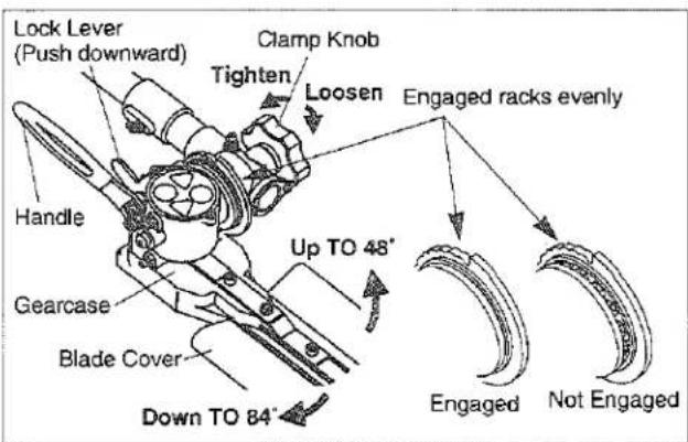
Folding procedure
- First stop the engine. Next attach the blade cover.
- Turn the clamp knob counter clockwise until the clamp knob stops. Folding the unit is not possible without the clamp knob completely loosend.
- Hold the handle security, and then fold the blades approximately 180 degrees while pushing the lock pin downward. Do not touch the lock lever except when folding the blades.
- After folding the unit, tighten the clamp knob firmly and fix the gearcase. When tightening the clamp knob make sure that both racks are engaged.
MC-T (Multi-Cutter with Cultivator Attachment)
CAUTION
- Read the Safety instructions on page US-13 concerning proper use of the Cultivator.
Before using the Cultivator, check the following:
- The operator must be set the Knapsack belt, and the shaft assembly must be on the operator's right side.
- The operator's right hand should be holding the shaft grip, with his or her fingers on the throttle trigger. The right arm should be slightly bent.
- The left hand should be holding the loop handle with the fingers and thumb fully enclosed around the grip. The left arm should be extended. Reposition the loop handle up or down the drive-shaft if necessary for a comfortable position.
- Do not operate the Cultivator in hard un-tilled soil or in rocky areas.
- Do not operate the Cultivator in areas with vines or tree roots.
-
Do not operate the Cultivator in water.
-
Always release the throttle trigger and allow the engine to return to idle speed when not cultivating.
- Stop the engine when moving between work sites.
CAUTION
• Always wear gloves and protective clothing when operating the Cultivator.
- The Cultivator should be operated only while traveling forward. Working the Cultivator with a back-and-forth motion while traveling produces the best results. A fast or slow engine-speed can be used according to soil conditions.
- If the cultivator tines become jammed, stop the engine immediately. Make certain all moving parts have stopped, and disconnect the spark plug before attempting to remove any obstruction.
• The cultivator gearcase becomes very hot during operation. Do not touch the gearcase.
• Make certain all moving parts have stopped and disconnect the spark plug before inspecting the equipment for damage. - Never use Cultivator that has cracked or broken tines.
Maintenance
Maintenance, replacement or repair of emission control devices and systems may be performed by any repair establishment or individual; however, warranty repairs must be performed by a dealer or service center authorized by Maruyama Manufacturing Company, Inc. The use of parts that are not equivalent in performance and durability to authorized parts may impair the effectiveness of the emission control system and may have a bearing on the outcome of a warranty claim.
Maintenance on today's low-emission engines is even more critical for longest life and best performance. particularly critical are air and fuel filters, spark plug heat range, cooling air intake area and proper gaps of coil and plug.
Engine
Air Filter
Maintenance Interval
• The air filter should be cleaned daily, or more often when working in extremely dusty conditions.
- Replace after every 100 hours of operation.
Air Filter
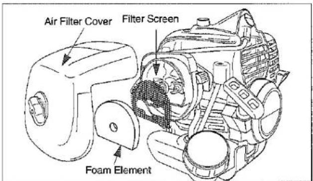
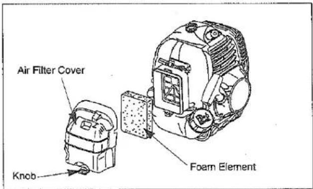
- Loosen the knob and remove the air filter cover.
- Remove the foam element and filter screen from the air filter body.
- Clean the foam element and filter screen with warm, soapy water. Let the screen and element dry completely.
- Apply a light coat of SAE 30 motor oil to the foam element and squeeze out all excess oil.
- Reassemble the filter screen, foam element and to the air filter cover.
[M30BK-S]
[M42BK]
Fuel Filter
Maintenance Interval
The fuel filter should be replaced after every 100 hours of operation.
Fuel filters needing more frequent replacement may indicate debris in fuel tank.
Fuel Filter Replacement
The fuel filter is attached to the end of the fuel pick-up hose inside the fuel tank.
- Make sure the fuel tank is empty.
- Remove the fuel cap.
- Using a wire hook, gently pull the fuel filter out through the fuel filler opening. Use caution not to "fishhook" the fuel tube. Replace immediately if punctured!
- Grasp the fuel hose next to the fuel filter fitting and remove the filter, but do not release the hose.
- While still holding on to the fuel hose, attach the new fuel filter.
- Drop the new fuel filter back into the fuel tank.
- Make sure that the fuel filter is not stuck in a corner of the tank, and that the fuel hose is not doubled over (kinked) before refueling.
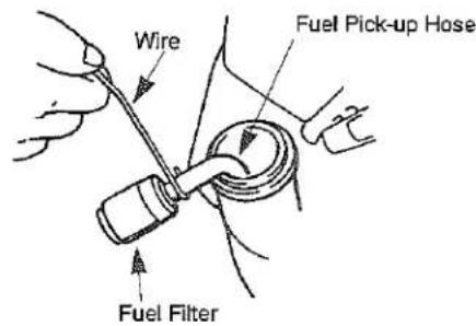
Spark Plug
Maintenance Interval
- The spark plug should be removed from the engine and checked after each 25 hours of operation.
- Replace the spark plug after every 100 hours of operation.
Spark Plug Maintenance
- Twist the high tension lead boot on the spark plug back and forth a couple of times to loosen the boot, then pull the boot off of the spark plug.
- Remove the spark plug.
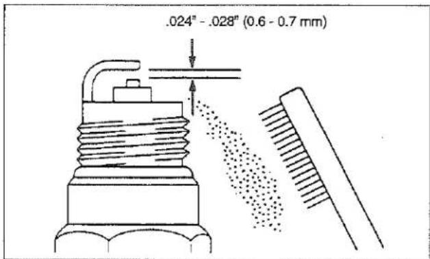
- Clean the electrodes with a stiff brush.
- Adjust the electrode air gap to .024-.028 in (0.6-0.7mm).
- Replace the spark plug if it is oil-fouled, damaged, or if the electrodes are worn down.
- Do not overtighten the spark plug when installing. The tightening torque is 95-148 in. lbs. (10.7-16.6 N·m).
- Always use only the specific heat range of spark plug. This is particularly critical with today's lowemission engines. For best results, use the exact replacement.
Cylinder Cooling Fins
Maintenance Interval
The cylinder cooling fins should be cleaned after every 25 hours of operation, or once a week, whichever comes first.
Air must flow freely around and through the cylinder cooling fins to prevent engine overheating. Leaves, grass, dirt and debris buildup on the fins will increase the operating temperature of the engine, which can reduce engine performance and shorten engine life.
Cooling Fin Cleaning
[M30BK-S]
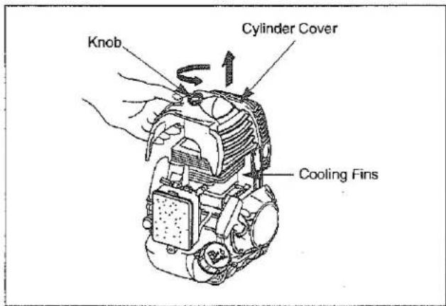
- With the engine at ambient (room) temperature, loosen the knob and remove the air filter cover.
- Twist the high tension lead boot on the spark plug back and forth a couple of times to loosen the boot, then pull the boot off of the spark plug.
- Loosen the knob and lift off the cylinder cover.
- Clean all dirt and debris from the cooling fins and from around the cylinder base.
- DO NOT overlook cleaning of the cooling air intake area below the crankcase and above the fuel tank! This area must be free of debris and obstruction for the engine to cool properly.
- Reinstall the fan cover and the filter cover.

[M42BK]
- With the engine at ambient (room) temperature, loosen the knob and remove the air filter cover.
- Loosen the knob and lift off the cylinder cover.
- Clean all dirt and debris from the cooling fins and from around the cylinder base.
- DO NOT overlook cleaning of the cooling air intake area below the crankcase and above the fuel tank! This area must be free of debris and obstruction for the engine to cool properly.
- Reinstall the cylinder cover.
Spark Arrester

WARNING
POTENTIAL HAZARD
- Muffler surface becomes hot when Trimmer/ Brushcutter is in operation and remains hot for some time after the engine is shut off.
WHAT CAN HAPPEN
- Contact with hot muffler surfaces could cause a burn.
HOW TO AVOID THE HAZARD
• Make sure the muffler is cool before inspecting and cleaning the spark arrester.
Maintenance Interval
- The spark arrester should be inspected and cleaned after every 25 hours of use.
- Replace the screen if it cannot be thoroughly cleaned, or if it is damaged.
Spark Arrester Maintenance
[M30BK-S]
- With the engine at ambient (room) temperature, loosen the knob and remove the air filter cover.
- Twist the high tension lead boot on the spark plug back and forth a couple of times to loosen the boot, then pull the boot off of the spark plug.
- Loosen the knob and lift off the cylinder cover.
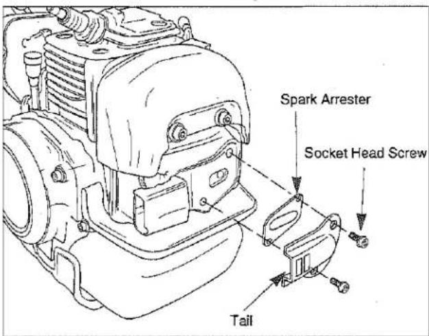
- Remove and clean the tail, gasket and spark arrester with a safety solvent and a stiff brush. If any part cannot be thoroughly cleaned, it must be replaced.
- Reinstall the spark arrester and tail onto the muffler, then reinstall and tighten the two socket head-screws.
- Reinstall the cylinder cover and the air filter cover.
[M42BK]
- With the engine at ambient (room) temperature, loosen the knob and remove the air cleaner cover.
- Loosen the knob and lift off the cylinder cover.
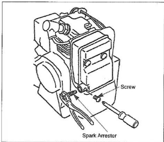
- Remove a screw located on the side of the exhaust outlet holds the spark arrester in place.
- Withdraw the spark arrester, using a suitable pair of pliers.
Note: Do not crush or distort the spark arrester flange during removal.
- The screen can be cleaned using a non-flammable solvent and stiff wire brush.
Note: If any part cannot be thoroughly cleaned, it must be replaced. - To install insert the spark arrester into the exhaust outlet while aligning the holes in the arrester flange and outlet for the retaining screw. Then install the screw.
- Reinstall the cylinder and air filter covers.
Exhaust Muffler
Maintenance Interval
The muffler should be inspected and cleaned after each 100 hours of use.
Muffler Maintenance
[M30BK-S]
- With the engine at ambient (room) temperature, loosen the knob and remove the air cleaner cover.
- Twist the high tension lead boot on the spark plug back and forth a couple of times to loosen the boot, then pull the boot off of the spark plug.
- Loosen the knob and lift off the cylinder cover.
- Remove the spark arrester (see spark arrester maintenance), Clean the muffler with a stiff brush.
IMPORTANT: Don't use solvent for cleaning inside of muffler, because of the catalytic converter in muffler.
Be careful not to allow any dirt or debris to fall into the exhaust port, as this can cause engine damage.
- Reinstall the spark arrester and tail onto muffler, then reinstall and tighten the two socket head screws.
- Reinstall the cylinder cover and the air filter cover.
[M42BK]
- With the engine at ambient (room) temperature, loosen the knob and remove the air filter cover.
- Loosen the knob and lift off the cylinder cover.
- Withdraw the spark arrester using a suitable pair of pliers.
Note: Do not crush or distort the spark arrester flange during removal.
- Remove the three socket head screws holding the muffler body from cylinder.
- Clean exhaust port of cylinder, exhaust outlet of muffler and spark arrester with safety solvent and stiff brush.
IMPORTANT: Be careful not to allow any dirt or debris to fall into the exhaust ports, as this can cause engine damage.
- To reassemble the muffler body to the cylinder, apply Removal Loctite to the three socket head screws, then reinstall and tighten the three screws.
- Reinstall the spark arrester onto the muffler body, then reinstall and tighten the screw.
- Reinstall the cylinder and air filter covers.
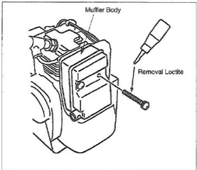
Flexible Shaft
Maintenance Interval
The flexible shaft should be lubricated after each 20 hours of operation
Flexible Shaft Lubrication
- Pull out the outer fitting from the clutch drum housing, with pulling up the pin.
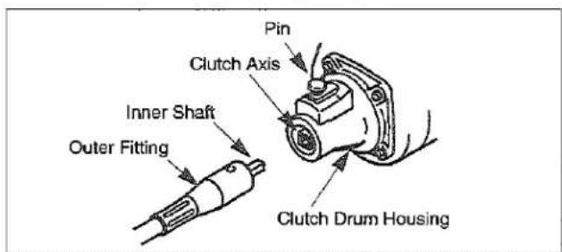
- Pull out the inner shaft from the flexible outer, and apply half a tubeful of grease to entire length of the inner shaft evenly.
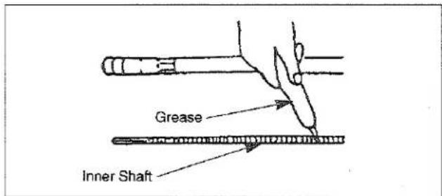
- Insert the inner shaft into the flexible outer and reinstall the outer fitting to the clutch drum housing, with pulling up the pin.
MC-SB (Straight Shaft Attachment) Gearcase
Maintenance Interval
The gearcase should be checked for lubrication after each 30 hours of use.
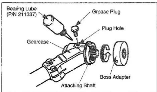
Gearcase Lubrication
Remove the cutting attachment and the boss adapter. Clean any dirt and debris from the area between the boss adapter and the gearcase. Remove the grease plug from the side of the gearcase. While rotating the attaching shaft, inject lithium-base bearing lube (P/N 211337) through the plug hole until the gearcase is full. Reinstall the boss adapter and grease plug.
MC-E (Edger Attachment) Flexible Driveshaft
Maintenance Interval
The Edger uses a flexible driveshaft inside the drive shaft tube. The flexible driveshaft should be lubricated after each 30 hours of use.
Flexible Drive Shaft Lubrication
- Loosen the two Socket head screws holding the gearcase to the driveshaft tube and carefully remove the gearcase from the driveshaft tube.
- Grip the end of the flexible driveshaft and remove it from the driveshaft tube.
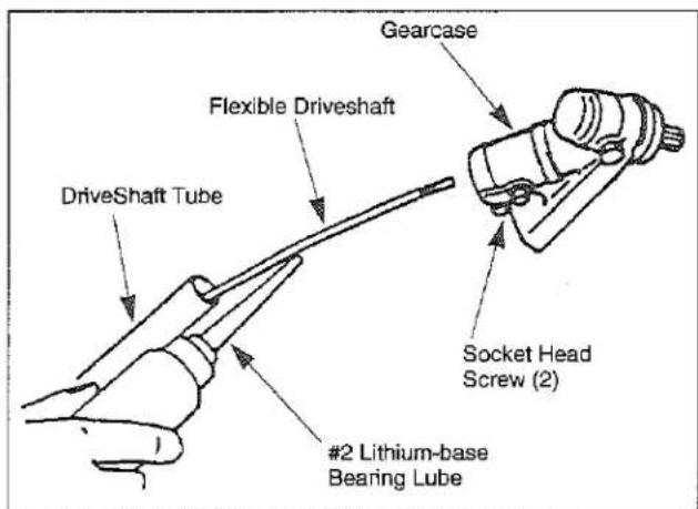
- Lubricate the flexible driveshaft with a high quality #2 lithium-base bearing lube.
- Reinstall the flexible driveshaft into the driveshaft tube. Twist the flexible driveshaft as you insert it into the to ensure that it seats into the clutch drum.
- Reinstall the gearcase onto the driveshaft tube, then tighten the two Socket head screws.
Gearcase
Maintenance Interval
The gearcase lubricant should be inspected after every
30 hours of use.
Gearcase Maintenance
Remove the cutting attachment and the boss adapter. Clean any dirt and debris from the area between the boss adapter and the gearcase. Remove the grease plug from the side of the gearcase. While rotating the attaching shaft, inject lithium-base bearing lube (P/N 211337) through the plug hole until the gearcase is full. Reinstall the grease plug.
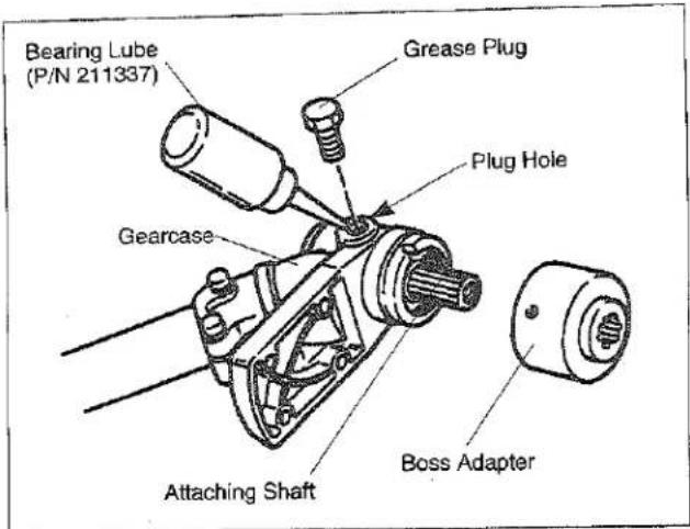
MC-PS (Pruner Attachment)
Lubrication
Maintenance Interval
The gearcase should be inspect after each 30 hours of use.
Lubrication
The gearcase should be checked for lubrication after each 10 hours of use. Grease fittings are installed into gearcase. Use #2 lithiumbase bearing lubricant.
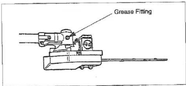
MC-HT/MC-HTS/MC-HTSL/MC-HTR (Hedge Trimmer Attachment)
Adjusting Cutting Blades
Maintenance Interval
CAUTION
• DO NOT TOUCH THE SHARPENED EDGES OF THE CUTTING BLADES. THE CUTTING BLADES ARE EXTREMELY SHARP AND DANGEROUS AT ALL TIMES.
Before operating the power Hedge Trimmer it is necessary to check the adjustment of the cutting blades.
Blades that are too loose may vibrate, and will not provide a clean, smooth cut.
Cutting Blades Maintenance
CAUTION-BLADES THAT ARE TOO TIGHT CAN CAUSE OVERLOADING WHICH MAY DAMAGE THE EQUIPMENT.
To adjust the cutting blades, refer to the illustrations and locate the tension screws.
Loosen the tension screw locknuts. Gently turn the tension screws in until sung, then turn the tension screws back out (MC-HT:1/4 turn, MC-HTS/MC-HTSL/MC-HTR:1/3-1/2 turn). While holding the screws in place, tighten the locknuts. Liberally coat the cutting blades with light oil. Start the engine and operate the Hedge Trimmer at full speed for at least one minute. Stop the engine, and when the blades are motionless, touch the blades with your hand.
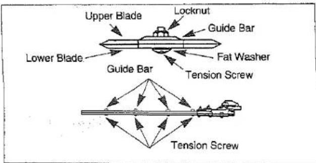
The blades may be warm, but if they are too hot to touch, loosen the tension screws 1/8 turn.
Lubrication
Maintenance Interval
The gearcase and angle drive should be inspect after each 10 hours of use.
Cutting blades should be lubricated at all times.
Lubrication
The gearcase and angle drive should be checked for lubrication after each 10 hours of use. Grease fittings are installed into both components. Use #2 lithiumbase bearing lubricant.
![Light Oil (#10wt.) Grease Fitting for Angle Drive Cutting Blade Grease Fitting for Gearcase [MC-HT]](/content/2026/05/1044597/images/1297802ee4a5084a3e3f4d0acc3295187a8a5bb0054c0850553e5cf210c67c7f.jpg)
![Grease Fitting for Angle Drive Light Oil (#10 wt.) Grease Fitting for Gearcase Grease Fitting for Angle Drive [MC-HTS/MC-HTSL]](/content/2026/05/1044597/images/50970581c6e0288015d0c281c5091c60518fdf655c794355162f3ae68d75f39e.jpg)
![Grease Fitting Light Oil (#10 wt.) 710 Grease Fitting Cutting Blade [MC-HTR]](/content/2026/05/1044597/images/542baf991602ec61a7e6233d6324c7133064710352d547005642e7e80f57e331.jpg)
Lubrication of the cutting blades should be maintained at all times. Use a light oil (#10wt.).
MC-T (Cultivator Attachment)
Lubrication
Maintenance Interval
The cultivator gearcase should be inspected after each 25 hours of use.
Lubrication
The cultivator gearcase holds 1.4 ounces of lubricant. A grease fitting is located in the top of the gearcase.
Lubricant should be checked at least every 25 hours of operation. Use a #2 lithium-based EP lubricant with Molybdenum additive.
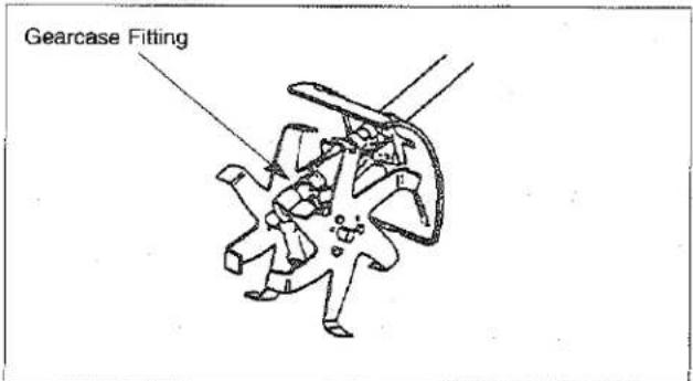
General Cleaning and Tightening
The Multi-Cutter will provide maximum performance for many, many hours if it is maintained properly.

WARNING
POTENTIAL HAZARD
- When engine is running, Attached Tool is rotating/ moving and other parts are moving.
WHAT CAN HAPPEN
- Contact with rotating/moving Tool or other moving parts could cause serious personal injury or death.
HOW TO AVOID THE HAZARD
• Always turn off your Multi-cutter before you clean or perform any maintenance on it.
Good maintenance includes regular checking of all fasteners for correct tightness and cleaning the entire machine.
Storage
For long term storage of the Multi-cutter:
- Empty the fuel tank into a suitable fuel storage container.
- Pump the primer bulb on the carburetor until all fuel is discharged through the clear fuel return hose.
- Run the engine to remove any fuel that may remain in the carburetor.
- Perform all regular maintenance procedures and any needed repairs.
- Remove the spark plug and squirt a very small amount of oil into the cylinder.
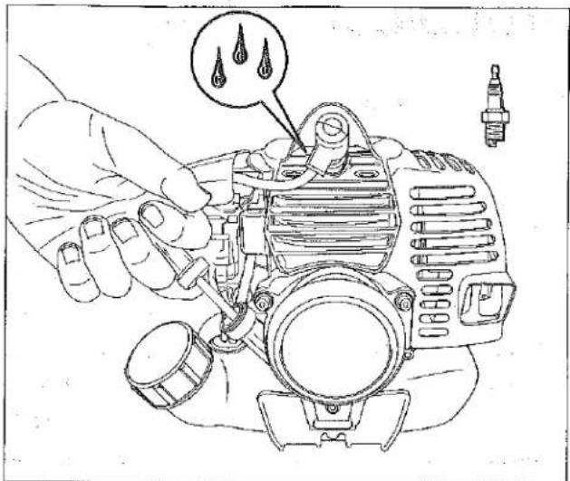

CAUTION
POTENTIAL HAZARD
- Oil may squirt out of the spark plug opening when you pull the starter grip.
WHAT CAN HAPPEN
- Oil can cause eye injuries.
HOW TO AVOID THE HAZARD
- Protect your eyes and keep your face away from the spark plug opening.
- Pull the starter grip once.
- Slowly pull the starter grip to bring the piston to the top of the cylinder (TDC).
- Reinstall the spark plug.
- Store the Multi-Cutter in a dry place away from excessive heat, sparks or open flame.
Troubleshooting
| Problem | Cause | Action |
| Engine Will Not Start | STOP switch set to off positionEmpty fuel tankPrimer bulb wasn't pushed enoughEngine flooded | Move switch to on positionFill fuel tankPress primer bulb until fuel flows through fuel return lineUse warm engine starting procedure |
| Engine Will Not Idle | Idle speed set incorrectly | Set idle speed |
| Engine Lacks Power or Stalls When Cutting | Throttle wire has come looseDirty air filterClogged spark arrester or exhaust port. | Tighten throttle wireClean or replace air filterClean spark arrester or exhaust port. |
If further assistance is required, contact your local authorized Maruyama service dealer.
Maintenance Period
| Maintenance | Daily | Every 20 hours | Every 50 hours | Every 100 hours | |
| Check and replenish fuel | |||||
| Check for fuel leakage | |||||
| Check bolts, nuts and screws for tightness or missing | |||||
| Tighten bolts and nuts | |||||
| Clean air filter element | |||||
| Clean spark plug and adjust electrode gap | |||||
| Remove dust and dirt from cylinder fins | |||||
| Remove carbon deposits in exhaust port | |||||
| Clean spark arrester | |||||
| Replace fuel filter | |||||
| Remove carbon deposits on piston head and combustion chamber | |||||
| Remove carbon deposits in transfer ports | |||||
| Replace fuel tube, fuel tank cap gasket | It is recommended to replace every 3 years | ||||
●: Service to be performed by an authorized Maruyama engine dealer.
: Service more frequently under dusty conditions.
NOTE:
The service intervals indicated are to be used as a guide.
Service to be performed more frequently as necessary depending on operating condition.
Use Maruyama standard 50:1 two-cycle engine oil.
Specifications
| M30BK-S with | ||||
| MC-SB | MC-E | MC-PS | MC-T | |
| Weight (lbs) | *120.3 (9.2kg) | *221.3 (9.7kg) | *323.1 (10.5kg) | 23.3 (10.6kg) |
| Engine Displacement (cm2) | 30.1 | |||
| Anti Vibration | Dual Isolation - grip and engine mount | |||
| Carburetor | Walbro Diaphragm Type | |||
| Ignition System | Solid State | |||
| Fuel Tank Capacity (qts.) | 1.06 (1.0 ) | |||
| Gas to Oil Ratio | 50:1 | |||
| Spark Plug | NGK BPM8Y | |||
| Spark Plug Gap (in.) | .024 -.028 (0.6 - 0.7 mm) | |||
| EPA and CARB Approved | Phase 3, Tier 3 | |||
| M30BK-S with | ||||
| MC-HT | MC-HTS | MC-HTSL | MC-HTR | |
| Weight (lbs) | 22.6 (10.3kg) | 22.0 (10.0kg) | 22.6 (10.2kg) | 23.6 (10.7kg) |
| Engine Displacement (cm3) | 30.1 | |||
| Anti Vibration | Dual Isolation - grip and engine mount | |||
| Carburetor | Walbro Diaphragm Type | |||
| Ignition System | Solid State | |||
| Fuel Tank Capacity (qts.) | 1.06 (1.0 ) | |||
| Gas to Oil Ratio | 50:1 | |||
| Spark Plug | NGK BPM8Y | |||
| Spark Plug Gap (in.) | .024 -.028 (0.6 - 0.7 mm) | |||
| EPA and CARB Approved | Phase 3, Tier 3 | |||
| M42BK with | ||||
| MC-SB | MC-E | MC-PS | MC-T | |
| Weight (lbs) | *126.2 (11.9kg) | *227.2 (12.6kg) | *328.9 (13.1kg) | 29.2 (13.2kg) |
| Engine Displacement (cm3) | 41.5 | |||
| Anti Vibration | Dual Isolation - grip and engine mount | |||
| Carburetor | Walbro Diaphragm Type | |||
| Ignition System | Solid State | |||
| Fuel Tank Capacity (qts.) | 1.06 (1.0 l) | |||
| Gas to Oil Ratio | 50:1 | |||
| Spark Plug | NGK BPM8Y | |||
| Spark Plug Gap (in.) | .024 -.028 (0.6 - 0.7 mm) | |||
| EPA and CARB Approved | Phase 3, Tier 3 | |||
| M42BK with | ||||
| MC-HT | MC-HTS | MC-HTSL | MC-HTR | |
| Weight (lbs) | 28.5 (12.9kg) | 27.9 (12.6kg) | 28.5 (12.9kg) | 29.4 (12.3kg) |
| Engine Displacement (cm3) | 41.5 | |||
| Anti Vibration | Dual Isolation - grip and engine mount | |||
| Carburetor | Walbro Diaphragm Type | |||
| Ignition System | Solid State | |||
| Fuel Tank Capacity (qts.) | 1.06 (1.0 ) | |||
| Gas to Oil Ratio | 50:1 | |||
| Spark Plug | NGK BPM8Y | |||
| Spark Plug Gap (in.) | .024 -.028 (0.6 - 0.7 mm) | |||
| EPA and CARB Approved | Phase 3, Tier 3 | |||
Emission durability of 300 hours.
*1. Dry weight without fuel and Cutting head. *2. Dry weight without fuel and Blade. *3. Dry weight without fuel, Chain, Bar and Rim.

Maruyama U.S., Inc.
3570 Shelby Lane
Denton, TX 76207 U.S.A
Phone 940-383-7400
Fax 940-383-7466
www.maruyama-us.com
232486-01 US/ES/FR 11.10 TAP/M
- The POWER in Outdoor Power
- This warranty does not cover the following:
- FEDERAL EMISSION CONTROL WARRANTY STATEMENT YOUR WARRANTY RIGHTS AND OBLIGATIONS
- Emission durability of 300 hours.
- MANUFACTURER'S WARRANTY COVERAGE:
- OWNER'S WARRANTY RESPONSIBILITIES:
- COVERAGE
- MAINTENANCE REQUIREMENTS
- LIMITATIONS
- CALIFORNIA EMISSION CONTROL WARRANTY STATEMENT YOUR WARRANTY RIGHTS AND OBLIGATIONS
- Emission System Parts
- Product description
- M30BK-S/M42BK
- (Multi-Cutter Power Unit)
- MC-SB
- (Straight Shaft Attachment)
- MC-E
- (Edger Attachment)
- MC-PS
- (Pruner Attachment)
- Contents
- Page US-
- Operation
- Introduction
- Safety
- Operator Safety
- Multi-Cutter with Tool Attachments Safety
- Fuel Safety
- Multi-Cutter with Tool Attachments Operating Safety
- String Trimmer Operating Safety
- Edger Operating Safety
- Pruner Operating Safety
- Hedge Trimmer Operating Safety
- Cultivator Operating Safety
- Safety and Instruction Decals
- MC-HTS/MC-HTSL/MC-HTR (Hedge Trimmer Attachment)
- Assembly
- Installing Flexible Shaft
- Loop Handle Installation
- Connecting Stop Switch Wires
- Connecting Throttle Cable
- Cable Adjustment
- MC-SB (Straight Shaft Attachment)
- Installing the Debris Shield
- WARNING
- POTENTIAL HAZARD
- WHAT CAN HAPPEN
- HOW TO AVOID THE HAZARD
- CAUTION
- Installing Trimmer Head
- MC-E (Edger Attachment)
- Installing Debris Shield
- Installing Edger Blade
- Note: The blade bolt has left-hand threads.
- MC-PS (Pruner Attachment)
- Installing Shaft and Gearcase
- Installing Guide Bar and Chain
- MC-T (Cultivator Attachment)
- Installing Shaft and Shield
- Connecting the Tool Attachments to the Power Unit
- Before Operation
- Chain Oil (Multi-Cutter with Pruner Attachment)
- Oil and Fuel
- ! DANGER
- Recommended Oil Type
- Recommended Fuel Type
- Use Of Fuel Additives
- Mixing Gasoline And Oil
- Fuel Mixture
- Mixing Instructions
- Starting And Stopping
- Before Starting The Engine
- Cold Starting Procedure
- Hot Restart
- To Stop The Engine
- Idle Speed Adjustment
- MC-SB (Multi-Cutter with Straight Shaft Attachment)
- Operating Position
- Cutting with Trimmer Head
- Trimming
- Scaling
- Mowing
- MC-E (Multi-Cutter with Edger Attachment)
- Setting Depth of Cut
- MC-PS (Multi-Cutter with Pruner Attachment)
- MC-HT/MC-HTS/MC-HTSL/MC-HTR (Multi-Cutter with Hedge Trimmer Attachment)
- Adjusting the angle of the blades (MC-HTS/MC-HTSL)
- Adjusting the angle of the blades (MC-HTR)
- Folding procedure
- MC-T (Multi-Cutter with Cultivator Attachment)
- Maintenance
- Engine
- Air Filter
- Maintenance Interval
- Fuel Filter
- Fuel Filter Replacement
- Spark Plug
- Spark Plug Maintenance
- Cylinder Cooling Fins
- Cooling Fin Cleaning
- [M30BK-S]
- [M42BK]
- Spark Arrester
- Spark Arrester Maintenance
- Exhaust Muffler
- Muffler Maintenance
- Flexible Shaft
- Flexible Shaft Lubrication
- MC-SB (Straight Shaft Attachment) Gearcase
- Gearcase Lubrication
- MC-E (Edger Attachment) Flexible Driveshaft
- Flexible Drive Shaft Lubrication
- Gearcase
- Gearcase Maintenance
- Lubrication
- MC-HT/MC-HTS/MC-HTSL/MC-HTR (Hedge Trimmer Attachment)
- Adjusting Cutting Blades
- Cutting Blades Maintenance
- CAUTION-BLADES THAT ARE TOO TIGHT CAN CAUSE OVERLOADING WHICH MAY DAMAGE THE EQUIPMENT.
- General Cleaning and Tightening
- Storage
- Troubleshooting
- Maintenance Period
- NOTE:
Brand : Maruyama
Model : MC-E
Category : Cutting machine