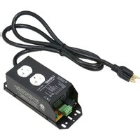
RPC-20-SCD-RJ - Commande d'alimentation électrique Lowell - Free user manual and instructions
Find the device manual for free RPC-20-SCD-RJ Lowell in PDF.


| Product Type | Rack-Mount Power Distribution Unit |
| Number of Outlets | 20 |
| Mounting | 19-inch rack, 1U height |
| Input Voltage | 120V~240V AC, 50/60 Hz |
| Maximum Current | 20A (typical) |
| Surge Protection | Built-in, 1400J (estimated) |
| Control Interface | RJ45 for remote on/off and monitoring |
| Dimensions (W x D x H) | 19 x 10 x 1.75 inches |
| Weight | 7.5 lbs (approx.) |
| Cord Length | 10 feet (typical) |
| Circuit Breaker | Resettable, 20A |
| Operating Temperature | 32°F to 122°F (0°C to 50°C) |
| Certifications | UL, CSA, RoHS compliant |
| Material | Steel chassis, black finish |
| Included Accessories | Mounting brackets, screws, user manual |
| Maintenance | Wipe with dry cloth; no user-serviceable parts |
| Safety Features | Overload protection, spike suppression |
| Warranty | 1 year (limited) |
Frequently Asked Questions - RPC-20-SCD-RJ Lowell
User questions about RPC-20-SCD-RJ Lowell
0 question about this device. Answer the ones you know or ask your own.
Ask a new question about this device
Download the instructions for your Commande d'alimentation électrique in PDF format for free! Find your manual RPC-20-SCD-RJ - Lowell and take your electronic device back in hand. On this page are published all the documents necessary for the use of your device. RPC-20-SCD-RJ by Lowell.
USER MANUAL RPC-20-SCD-RJ Lowell

Intertek
(1)
Components

Made In USA
with Global
Components

Certified
US Steel
[Non-Text]
Ideal for Lowell switches featuring maintained closure (order separately):
RPSB-P-RJ Black wall plate w/rocker switch & RJ45
RPSW-P-RJ White wall plate w/rocker switch & RJ45
RPSW-KP-RJ White wall plate w/key switch & RJ45
RPSB-R-RJ Rack panel w/rocker switch & RJ45
RPSB-KR-RJ Rack panel w/key switch & RJ45
Model No.
RPC-20-SCD-RJ
Remote Power Control
actives remote equipment — external trigger required
REMOTE POWER CONTROLS can be combined with a variety of switches or sequencers (with dry contact closure or voltage trigger) for an intrinsically safe, low voltage method of controlling AC power to equipment at remote locations. Controlling power distribution without directly accessing equipment minimizes the potential for unauthorized access, while simplifying activation and deactivation of equipment.
Note: RPCs require an external trigger for activation (order separately).
FEATURES
CHASSIS: Steel chassis (8.00"L x 3.25"W x 2.75"H) with black finish and mounting holes.
POWER:
• Power Rating: 125VAC 60Hz 20A
- Outlets: NEMA 5-20R duplex
- Attached Cord: 6 ft. cord with NEMA 5-20P plug
SURGE PROTECTION:
• Maximum Surge Current: 20,000A
• VPR: 400V
• Response Time: 1 nanosecond
• EMI/RFI Noise Reduction: 20dB@100kHz
• Protection Mode: Line to Neutral
• Ground Contamination: None
ACTIVATION: Must be connected to an external control for activation and deactivation (choose one):
- Dry Contact Closure: Connect to SPST switch, power sequencer, or independent control system with dry contact closure.
Contact Coil Rating:
- Voltage: 24VDC
- Current: 37.5mA
- Voltage Trigger (5-24V AC or DC 5mA): DSP connection.
ORIGIN: Made in the U.S.A. with global components
THIRD PARTY APPROVAL: ETL Listed to UL60065 (U.S. and Canada)
INSTALLATION: The RPC is typically installed near the equipment to be controlled. Low voltage cable is run from its RJ45 connector (or terminal strip) to a control switch (or other control method).
- Systems can be configured with multiple RPCs controlled by a single "Maintained Closure" switch or voltage trigger source.
- Systems can also be configured with a single RPC controlled by multiple "Momentary Closure" switches and Lowell's MSM2 module (which converts momentary closure to maintained).
COMPATIBLE DEVICES: (order separately)
- SPST Switch (RPS Series): Low voltage wall-mount or rack-mount switch:
- Switch with maintained closure connects directly to RPC.
- Switch with momentary closure requires Lowell conversion module MSM2 placed between the switch and RPC.
- Power Sequencer (SEQ Series): A low voltage sequencer can be used with the RPC for time-delayed activation and deactivation of connected equipment. Lowell standalone sequencers will require a switch for activation, while Lowell rack-mount sequencers include a switch. See product spec sheets for information.
A&E SPECIFICATIONS
The device for remotely controlling AC power shall be Lowell model RPC-20-SCD-RJ, which shall feature a 8.00"L x 3.25"W x 2.75"H steel chassis with black powder epoxy finish, 125VAC 60Hz 20A power rating, one NEMA 5-20R duplex outlet, 6 ft. cord with NEMA 5-20P plug, and basic surge protection up to 20,000A. The unit shall require an external trigger for activation (not included).


SERIES OVERVIEW
| Model No. | Chassis | Outlets | Input | Power Rating | Surge Suppression | External Activation Required | Connections |
| RPC-15 | Standalone | NEMA 5-15R (2) | 6' attached cord | 125VAC 60Hz 15A | --- | Dry contact closure | Terminal Strip |
| RPC-15-S | Standalone | NEMA 5-15R (2) | 6' attached cord | 125VAC 60Hz 15A | Yes | Dry contact closure | Terminal Strip |
| RPC-15-SCD-RJ | Standalone | NEMA 5-15R (2) | 6' attached cord | 125VAC 60Hz 15A | Yes | Dry contact closure or VT* | TS or RJ45 |
| RPC-15-U | Standalone | IEC C13 (2) | 6' detachable cord (2) | 100-240VAC 50/60Hz 15A | --- | Dry contact closure or VT* | Terminal Strip |
| RPC-20-CD | Standalone | NEMA 5-20R (2) | 6' attached cord | 125VAC 60Hz 20A | --- | Dry contact closure or VT* | Terminal Strip |
| RPC-20-SCD | Standalone | NEMA 5-20R (2) | 6' attached cord | 125VAC 60Hz 20A | Yes | Dry contact closure or VT* | Terminal Strip |
| RPC-20-SCD-RJ | Standalone | NEMA 5-20R (2) | 6' attached cord | 125VAC 60Hz 20A | Yes | Dry contact closure or VT* | TS or RJ45 |
| RPC-3N1 | Standalone | NEMA 5-15R (8) | 6' attached cord | 125VAC 60Hz 15A | --- | Dry contact closure | Terminal Strip |
| RPC-4CD | Rack-mount | NEMA 5-15R (8) | 6' attached cord | 125VAC 60Hz 15A | --- | Dry contact closure | Terminal Strip |
| RPC-20-HW | Standalone | NEMA 20A (2) | 6' flexible whip | 125VAC 60Hz 20A | --- | Dry contact closure or VT* | Terminal Strip |
| RPC-20-SHW | Standalone | NEMA 20A (2) | 6' flexible whip | 125VAC 60Hz 20A | Yes | Dry contact closure or VT* | Terminal Strip |
| RPC-30-SHW | Standalone | Twistlock 30A (1) | 6' flexible whip | 125VAC 60Hz 30A | Yes | Dry contact closure or VT* | Terminal Strip |
* VT indicates the RPC can also accept a voltage trigger provided by an independent control system.
RPC DIAGRAM:
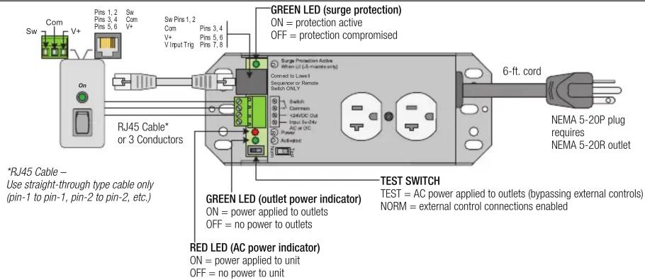
RPC TYPICAL CONTROL METHODS (low voltage, limited current Class 2 wiring):
See Lowell RPS Series models listed on pg. 1.
EXAMPLE 1: SPST switch with MAINTAINED closure.

EXAMPLE 2: Sequencer or Control System.
Lowell SEQ Series sequencer or control system by others.
![graph LR A["Sequencer or Control System"] --> B["Com (-)"] B --> C["Switch"] B --> D["Common"] C --> E["No Conn."] D --> F["No Conn."] E --> G["+24VDC Out (250mA max.)"] F --> H["Trigger In (5V-24V AC or DC)"]](/content/2026/05/1044570/images/ab03552e383a7bf4620322d5f6b97081d84d8ed1a8743ee2b5c696f71419ecaa.jpg)
Follow polarity indicators, if any, on sequencer/controller (rating: 24V, 37.5mA)
ON = connection applied (closed)
OFF = connection removed (open)
Voltage input from external control system (by others).
EXAMPLE 3: Voltage Input.
![graph LR A["(-)"] --> B["No Conn."] C["(+)"] --> D["No Conn."] B --> E["Switch"] D --> F["Trigger In (5V-24V AC or DC)"] E --> G["+24VDC Out (250mA max.)"] F --> G](/content/2026/05/1044570/images/996a3421e3a22652fdcc0b685d22159d2b1355103fe6546f4c7a35e190fe079c.jpg)
5V-24V, AC or DC, 5mA
ON = voltage applied
OFF = voltage removed
Application Example: RPC controls power to music/paging system. A signal from Fire Alarm Panel forces music/paging system OFF so an alarm can be heard.
from Fire Alarm System.
Closed loop from Fire Alarm Panel holds RPC ON. When loop is opened by Fire Alarm Panel, the RPC turns OFF.
EXAMPLE 4: Fire Alarm Panel Interface.
Normally Closed (N.C.) line

Normally Open (N.O.) line
from Fire Alarm System.
Voltage from +24V Out, Alarm System through a resistor, * to Trigger In holds power to outlet ON. Shorting Trigger In to Com via Fire Alarm Panel contact closure forces power to outlet OFF.


Brand : Lowell
Model : RPC-20-SCD-RJ
Category : Commande d'alimentation électrique