ACD-2000QT - Uncategorized ACTi - Free user manual and instructions
Find the device manual for free ACD-2000QT ACTi in PDF.


| Brand | ACTi |
| Model | ACD-2000QT |
| Product Type | Surveillance Camera |
| Image Sensor | 1/2.8" Progressive Scan CMOS |
| Resolution | 2 Megapixels (1920 x 1080) |
| Lens | Fixed 4mm |
| Night Vision | Up to 30m |
| Power Supply | PoE (802.3af) or DC 12V |
| Power Consumption | 6W (max) |
| Dimensions (W x H x D) | 70 x 70 x 180 mm |
| Weight | 0.5 kg |
| Operating Temperature | -10°C to 50°C |
| Video Compression | H.265, H.264 |
| Audio | Two-way audio |
| Network Interface | 10/100 Base-T Ethernet |
| Main Functions | Motion detection, night vision, ONVIF support |
| Maintenance | Clean lens with soft dry cloth. Avoid liquids. |
| Safety | Use only certified power adapter. Do not disassemble. |
| Spare Parts | Contact ACTi support for replacement parts. |
| Reparability | Not user-serviceable. Refer to qualified personnel. |
Frequently Asked Questions - ACD-2000QT ACTi
User questions about ACD-2000QT ACTi
0 question about this device. Answer the ones you know or ask your own.
Ask a new question about this device
Download the instructions for your Uncategorized in PDF format for free! Find your manual ACD-2000QT - ACTi and take your electronic device back in hand. On this page are published all the documents necessary for the use of your device. ACD-2000QT by ACTi.
USER MANUAL ACD-2000QT ACTi
natural_image
Abstract geometric design with overlapping triangular shapes and a white triangle, no text or symbols present.4-channel MPEG-4 Video Encoder
ACD-2000Q/ACD-2000QT
Ver. 090327
Hardware User's Manual

ACTi
www.acti.com
0 RECAUTIONS
1. Read these instructions
All the safety and operating instructions should be read before the product is operated.
2. Heed all warnings
All warnings on the product and in the instruction manual should be adhered to.

The symbol indicates the following items, please carefully read the description next to each symbol.
a. Failure to follow the safety instruction given may directly endanger people, cause damage to the system or to other equipment.
b. The requirements to make this device work, including hardware, computer settings, network settings, and operation procedures.
c. The tips to make using this device easier, more convenient and more efficient.
3. Servicing
Do not attempt to service this video product yourself as opening or removing covers may expose you to dangerous voltage or other hazards. Refer all servicing to qualified service personnel.
Trademarks
All names used in this manual for hardware and software are probably registered trademarks of respective companies.
Liability
Every care has been taken during writing this manual. Please inform your local office if you find any inaccuracies or omissions. We cannot be held responsible for any typographical or technical errors and reserve the right to make changes to the product and manuals without prior notice.
FCC/CE Regulation
NOTE: This equipment has been tested and found to comply with the limits for a Class A digital device, pursuant to Part 15 of the FCC Rules. These limits are designed to provide reasonable protection against harmful interference when the equipment is operated in a commercial environment. This equipment generates, uses,
and can radiate radio frequency energy and, if not installed and used in accordance with the instruction manual, may cause harmful interference to radio communications. Operation of this equipment in a residential area is likely to cause harmful interference in which case the user will be required to correct the interference at his own expense.
Table of Contents
0 PRECAUTIONS.... 0-1
Trademarks 0-1
Liability....0-1
FCC/CE Regulation 0-1
1 INTRODUCTION.... 1-1
1.1 Package Contents....1-1
1.2 Features and Benefits.... 1-2
1.3 Safety Instructions 1-4
1.4 Physical Description.... 1-6
1.5 Basic Connections.... 1-9
1.6 Product Specification.... 1-11
1 INTRODUCTION
1.1 Package Contents
ACD-2000Q
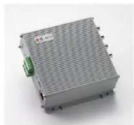
natural_image
Exterior view of a gray industrial control unit with a green indicator light and red label (no readable text or symbols)Warranty Card
Software CD
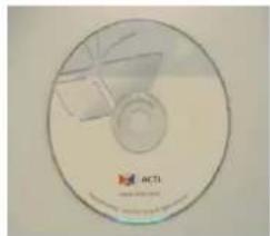
natural_image
Circular optical disc with internal components and a logo (no readable text or symbols)Terminal Blocks & Screws
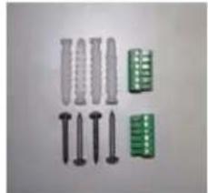
natural_image
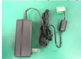
Collection of screw and connector components (no text or symbols visible)Power Adaptor (Option)
natural_image
Electrical power adapter with attached cable and connector (no visible text or symbols)1.2 Features and Benefits
This 4-channel MPEG-4 Video Encoder is a cutting-edge digital video transmission device. It can compress and transmit real time images with outstanding images quality at reasonable bandwidth through a standard TCP/IP network. That's because it is Ethernet (LAN and WAN) ready and has the powerful ARM9 SoC and the MPEG-4 compression ASIC inside. In addition, with these powerful hardware platform, excellent SDK support and powerful respective apparatuses (e.g. the transcoder), this 4-channel MPEG-4 Video Encoder is your best choice building up either conventional IP surveillance system or intelligent IP surveillance system.
Real-time MPEG-4 Compression
With hardware MPEG-4 compression chip inside, the composite video inputs can be efficiently compressed into MPEG-4 bit stream without any delay. The ASIC base compression engine can support not only CIF, but also FULL D1 image resolution.
Digital Time Code Embedded
The “Digital Time Code Embedded” function is to embed the recording time in the MPEG bit stream. Therefore, each image frame has its respective time when it was recorded. It is very useful when users want to find the video at an exact time or between a certain time intervals.
DDNS Supported
The Video Encoder supports DDNS (Dynamic Domain Name Server), users can set this IP device at a virtual domain name (such as cam1.Taipei.xxx) at dynamic IP. Everyone can use the virtual domain name to view the video anywhere that has the access to the internet.
Build-in Hardware Motion Detection
No more external motion sensors are required. Each Video Encoder can be set up to 3 detection areas. By tuning the object size and sensitivity, it is very reliable to fit into your environment. Besides, hardware motion detection delivers better sensitivity and responds faster than software motion detection.
Bundle Powerful Surveillance Software
To extend the capabilities of the Video Encoder, a powerful surveillance program is included in the package and is very free to use.
Users can easily utilize the existing PC to be a digital video recorder. Schedule recording and manual recording keep every important image recorded in the local hard disk. Reliable and accurate motion detection with instant warning makes you responsive in every condition. Quick and simple search and playback function lets you easily find the images you want.
Software Development Kit Support
The Video Encoder can be integrated or controlled by user's application program through the Streaming Library or ActiveX control. With its high level programming interface, software developer's time and efforts to is highly reduced.
1.3 Safety Instructions
Don't use the power supply with other voltages
This device is likely to be damaged or damage other equipments / personnel, if you use a power supply with different voltage than the one included with this device. All warranty of this product will be voided in the situations above.
Don't open the housing of the product
Cleaning
Disconnect this video product from the power supply before cleaning.
Attachments
Do not use attachments not recommended by the video product manufacturer as they may cause hazards.
Water and Moisture
Do not use this video product near water, for example, near a bathtub, washbowl, kitchen sink, or laundry tub, in a wet basement, or near a swimming pool and the like.
Don't use accessories not recommended by the manufacturer
- Only install this device and the power supply in a dry place protected from weather
- Servicing
Do not attempt to service this video product yourself as opening or removing covers may expose you to dangerous voltage or other hazards. Refer all servicing to qualified service personnel.
Damage Requiring service
Disconnect this video product from the power supply immediately and refer servicing to qualified service personnel under the following conditions.
- When the power-supply cord or plug is damaged.
- If liquid has been spilled, or objects have fallen into the video product.
-
If the video product has been exposed to rain or water directly.
-
If the video product does not operate normally by following the operating Instructions in this manual. Adjust only those controls that are covered by the instruction manual as an improper adjustment. Other controls may result in damage and will often require extensive work by a qualified technician to restore the video product to its normal operation.
Safety Check
Upon completion of any service or repairs to this video product, ask the service technician to perform safety checks to determine that the video product is in proper operating condition.
1.4 Physical Description
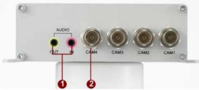
1. Audio Input / Output
The Video Encoder supports one audio input and output with earphone jack
2. CAM1, CAM2, CAM3 and CAM4
Analog Video Input of Composite Signal with BNC Connectors.
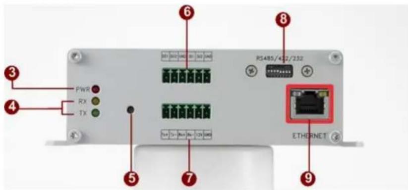
3. Action LED Indicator
The LED will light up after Video Encoder has successfully completed the boot process.
4. Serial Port LED Indicator
LEDs indicating when serial port is active.
5. Reset Button
Step 1: Switch off Video Encoder by disconnecting the power cable
Step 2: Using a suitable pointed object, press and continue to hold the Reset Button depressed. While continuing to hold the reset
button depressed, reconnect the power cable.
Step 3: Keep holding the reset button depressed around 6 seconds, release the reset button. The unit will start up with factory default settings.
6. Terminal Blocks Pin 1\~6
The Video Encoder supports two alarm input and two alarm output. DI: Logic Level 0: 0\~0.4V; Logic Level 1: 3.3\~30V DO: Logic Level 0: 0.1\~0.6V; Logic Level 1: 2.4\~5V Please find Support package" TS-00045" for details.
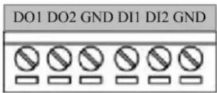
| PIN | NAME | DESCRIPTION |
| 1 | DO1 | Digital Output 1 |
| 2 | DO2 | Digital Output 2 |
| 3 | GND | Ground Pin |
| 4 | DI1 | Digital Input 1 |
| 5 | DI2 | Digital Input 2 |
| 6 | GND | Ground Pin |
Please find Support package" TS-00045" for details.
7. Terminal Blocks Pin 7\~12
Pin 7\~10: RS232/422/485. Default mode is RS-485
Pin 11\~12: DC 12V power input
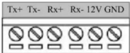
| PIN | NAME | DESCRIPTION | ||
| RS-485 | RS-422 | RS-232 | ||
| 7 | Tx+ | D+ | Tx+ | Tx |
| 8 | Tx- | D- | Tx- | |
| 9 | Rx+ | Rx+ | Rx | |
| 10 | Rx- | Rx- | ||
| 11 | 12V | Power Input (DC +12V) | ||
| 12 | GND | Ground Pin of Power Input | ||
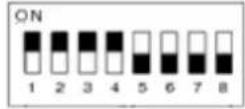
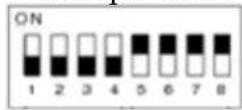
8. Dip Switch for Serial Port
RS-485 or RS-422 pin define (default is RS-485)
RS-232 pin define
9. Ethernet Port
The Video Encoder connects to the Ethernet via a standard RJ45 connector. Supporting NWAY, this IP device can auto detect the speed of local network segment (10Base-T/100Base-TX Ethernet).
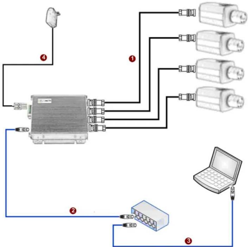
1.5 Basic Connections
Follow the procedures below to connect the Video Encoder to the respective apparatuses.
flowchart
graph TD
    A["Device 1"] -->|①| B["External Device"]
    A -->|②| C["External Device"]
    A -->|③| D["Laptop"]
    A -->|④| E["External Device"]
    B --> F["External Devices"]
    C --> G["External Devices"]
    D --> H["External Device"]
- Connect an analog video source (e.g. CCD Camera) to the Video Encoder's CAM1 \~ CAM4(BNC connector).
- Connect the Video Encoder's ethernet port to an Ethernet (RJ45 connectors)
- Connect a PC to the Ethernet hub (RJ45 connectors)
- Connect a power adaptor to the Video Encoder (terminal block connector)
1.6 Product Specification
| ACD-2000Q / ACD-2000QT | ||
| Video Compression | Compression | MPEG-4 SP, MJPEG selectable |
| Picture Resolution | Quad Mode :Full D1 (720x480 in NTSC, 720x576 in PAL)Sequential Mode :Full D1 (720x480 in NTSC, 720x576 in PAL)(per channel)Single Mode :Full D1 (720x480 in NTSC, 720x576 in PAL)(per channel)CIF (352 x 240 in NTSC, 352 x 288 in PAL)(per channel) | |
| Bit Rate | 28K ~ 3M bps | |
| Image Frame Rate | Quad Mode :30fps at full D1 resolution (NTSC)25fps at full D1 resolution (PAL)Sequential Mode :30fps at full D1 resolution (NTSC)25fps at full D1 resolution (PAL)Single Mode :7fps at full D1 resolution (NTSC / PAL)15fps at CIF resolution (NTSC)12fps at CIF resolution (PAL) | |
| Multi-stream | Up to 2 configurable frame rate/bit rate streams for preview and recording | |
| Video Input | Composite Input | 4, CVBS, 1.0Vp-p with 75Ω loading, BNC Connector |
| Audio Input | Compression | 8kHz, Mono, PCM |
| Audio Line Input | Unbalanced, 1.4 Vpp, 1Vrms, 3.5 mm Phone Jack | |
| Audio Output | Compression | 8kHz, Mono, PCM |
| Audio Line Output | Unbalanced, 1.4 Vpp, 1Vrms, 3.5 mm Phone Jack | |
| Alarm | Input | 2, TTL, Terminal Block |
| Output | 2, TTL, Terminal Block | |
| Remote Control | Serial Port | RS-485: Half Duplex, Terminal BlockRS-422: Full Duplex, Terminal BlockRS-232: Full Duplex, Terminal Block |
| External I/O | Reset Button | Factory Default |
| LED | Power / serial port / network status | |
| Network | Ethernet Port | Ethernet(10/100 Base-T), RJ45 Connector |
| Protocol | TCP, UDP, IP, HTTP, DHCP, PPPoE, RTP, RTSP, FTP, SMTP, DNS, DDNS, NTP, ICMP, IGMP, ARP | |
| Software | Web Browser | Microsoft Internet Explorer 6.0 or above |
| SDK | ACTi SDK-10000 | |
| Security | Password Protection: Configured by the Administrator | |
| Operating | Temperature | -10~50°C (14~122°F); ACD-2000Q-30~70°C (-22~158°F); ACD-2000QT |
| Power | Power Requirement | DC12V±10% |
| Power Consumption | 5.0W | |
| Physical | Dimensions | 119 x 41.7 x 122 mm (4.69" x 1.65" x 4.81") |
| Weight-Net | 430 g (0.95 lb) |
- 4-channel MPEG-4 Video Encoder
- ACD-2000Q/ACD-2000QT
- Hardware User's Manual
- RECAUTIONS
- Read these instructions
- Heed all warnings
- Servicing
- Trademarks
- Liability
- FCC/CE Regulation
- Table of Contents
- PRECAUTIONS.... 0-1
- INTRODUCTION.... 1-1
- INTRODUCTION
- Package Contents
- Features and Benefits
- Real-time MPEG-4 Compression
- Digital Time Code Embedded
- DDNS Supported
- Build-in Hardware Motion Detection
- Bundle Powerful Surveillance Software
- Software Development Kit Support
- Safety Instructions
- Don't use the power supply with other voltages
- Don't open the housing of the product
- Cleaning
- Attachments
- Water and Moisture
- Don't use accessories not recommended by the manufacturer
- Damage Requiring service
- Safety Check
- Physical Description
- Audio Input / Output
- CAM1, CAM2, CAM3 and CAM4
- Action LED Indicator
- Serial Port LED Indicator
- Reset Button
- Terminal Blocks Pin 1\~6
- Terminal Blocks Pin 7\~12
- Dip Switch for Serial Port
- Ethernet Port
- Basic Connections
- Product Specification
Brand : ACTi
Model : ACD-2000QT
Category : Uncategorized