GV-DFK1355 - Security Access Control System Geovision - Free user manual and instructions
Find the device manual for free GV-DFK1355 Geovision in PDF.


| Product Type | Security Access Control System |
| Brand | Geovision |
| Model | GV-DFK1355 |
| Dimensions (approx.) | 150 mm x 80 mm x 30 mm |
| Weight (approx.) | 0.5 kg |
| Power Supply | 12V DC, 1.5A |
| Main Functions | Face recognition, card reader, door lock control, alarm output, event logging |
| Recognition Method | Face biometrics (IR and visible light), RFID card (13.56 MHz) |
| User Capacity | Up to 10,000 face templates, 100,000 card users |
| Communication | TCP/IP, RS-485, Wiegand input/output |
| Display | 2.8-inch TFT color touchscreen |
| Camera | 2 MP wide-angle lens with IR illumination |
| Operating Temperature | -10°C to 50°C |
| Ingress Protection | IP65 (indoor/outdoor use) |
| Mounting | Wall mount (bracket included) |
| Maintenance & Cleaning | Clean lens and housing with soft dry cloth; avoid abrasive cleaners |
| Safety Features | Tamper alarm, anti-passback, duress mode |
| Spare Parts & Repairability | Replaceable face module, mainboard, and power adapter; contact Geovision support |
| General Information | Compatible with Geovision GV-Series software; supports remote management |
Frequently Asked Questions - GV-DFK1355 Geovision
User questions about GV-DFK1355 Geovision
0 question about this device. Answer the ones you know or ask your own.
Ask a new question about this device
Download the instructions for your Security Access Control System in PDF format for free! Find your manual GV-DFK1355 - Geovision and take your electronic device back in hand. On this page are published all the documents necessary for the use of your device. GV-DFK1355 by Geovision.
USER MANUAL GV-DFK1355 Geovision
natural_image
Product display of GeoVision mobile phone modules including keypad, door lock, and control panel (no visible text or symbols)Before attempting to connect or operate this product, please read these instructions carefully and save this manual for future use.
© 2023 GeoVision, Inc. All rights reserved.
Under the copyright laws, this manual may not be copied, in whole or in part, without the written consent of GeoVision.
Every effort has been made to ensure that the information in this manual is accurate.
GeoVision, Inc. makes no expressed or implied warranty of any kind and assumes no responsibility for errors or omissions. No liability is assumed for incidental or consequential damages arising from the use of the information or products contained herein. Features and specifications are subject to change without notice.
GeoVision, Inc.
9F, No. 246, Sec. 1, Neihu Rd.,
Neihu District, Taipei, Taiwan
Trademarks used in this manual: GeoVision, the GeoVision logo and GV series products are trademarks of GeoVision, Inc. Windows is the registered trademark of Microsoft Corporation.
MIFARE and DESFire are registered trademarks of NXP B.V.
November 2023
Scan the following QR codes for product warranty and technical support policy:

[Warranty]

[Technical Support Policy]
Notice
Notice for GV-R1352 V2B and GV-R1352 V2C: This device complies with Part 15 of the FCC Rules. Operation is subject to the following two conditions: (1) This device may not cause harmful interference, and (2) This device must accept any interference received, including interference that may cause undesired operation.
Notice for GV-RKD1352
Federal Communication Commission Interference Statement
This equipment has been tested and found to comply with the limits for a Class B digital device, pursuant to Part 15 of the FCC Rules. These limits are designed to provide reasonable protection against harmful interference in a residential installation.
This equipment generates, uses and can radiate radio frequency energy and, if not installed and used in accordance with the instructions, may cause harmful interference to radio communications. However, there is no guarantee that interference will not occur in a particular installation. If this equipment does cause harmful interference to radio or television reception, which can be determined by turning the equipment off and on, the user is encouraged to try to correct the interference by one of the following measures:
- Reorient or relocate the receiving antenna.
- Increase the separation between the equipment and receiver.
- Connect the equipment into an outlet on a circuit different from that to which the receiver is connected.
- Consult the dealer or an experienced radio/TV technician for help.
FCC Caution: To assure continued compliance, any changes or modifications not expressly approved by the party responsible for compliance could void the user's authority to operate this equipment. (Example - use only shielded interface cables when connecting to computer or peripheral devices).
Preface
Welcome to the GV-Card Reader User's Manual.
This Manual applies to the following GV-Card Readers:
| Reader Models |
| GV-Reader1251 and 1352 V2 |
| GV-SR1251 |
| GV-RK1352 / R1352 |
| GV-DFR1352 (Rev. B) |
| GV-DFK1355 |
| GV-RKD1352 |
| GV-R1355 |
| GV-RKR1355 |
| GV-RKV1355 |
| GV-R1354 |
Some GV reader models support MIFARE® DESFire®, MIFARE Plus® and MIFARE Classic® access cards and tags. For details, you may refer to the product's datasheet.
Naming and Definition
| Name | Description |
| UID | A type of card number; stands for Unique Identifier. |
| GID | A type of card number; stands for GeoVision Identifier. |
| DES-ID | A type of card number used for MIFARE® DESFire® cards. |
Note for Waterproofing
To prevent water from penetrating the reader from the rear panel, use the following waterproofing measures when installing GV-DFK1355, GV-RKV1355, GV-RKR1355, or GV-RKD1352.
- The rear panel of GV-DFK1355 or GV-RKV1355 has waterproofing rubber rings. Install the reader tightly against the wall to prevent water from entering along the wall. Apply silicone sealant to the sides of the reader if it is mounted on an uneven surface.
- Apply silicone sealant to the sides of GV-RKR1355 or GV-RKD1352 readers to prevent water from entering along the wall.
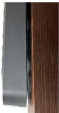
natural_image
Close-up of a dark gray panel and a wooden panel with visible grain texture (no text or symbols)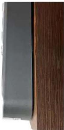
natural_image
Close-up of a dark rectangular object next to a wooden panel with vertical striations (no text or symbols visible)(X) A gap between the wall and the reader (O) The reader against the wall
Contents
Notice....ii
Preface....iii
Naming and Definition....iii
Note for Waterproofing....iv
Contents ...... v
Chapter 1 GV-Reader1251 / 1352 V2 and GV-SR1251....1
1.1 Packing List.... 1
1.2 Installation.... 2
1.2.1 Electric Wire 2
1.2.2 Switch Settings of GV-Reader1251 / 1352 V2 2
1.2.3 Define the ID of GV-SR1251 4
1.3 Connect the Reader to GV-AS Controller 5
1.3.1 Connect through Wiegand Interface 5
1.3.2 Connect through RS-485 Interface 6
1.3.3 Connect to GV-DVR/NVR and Third-Party Controllers 8
1.4 Overlay Card Numbers on GV-DVR/NVR Live View....9
1.5 Control the Beeper and LED....10
1.6 Specifications....11
Chapter 2 GV-RK1352 / R1352 / DFR1352....12
2.1 Packing List....13
2.2 Physical Descriptions ....14
2.2.1 Electric Wire 14
2.2.2 Keypad (GV-RK1352 Only) 16
2.2.3 LED and Beeper....16
2.3 Connect the Reader to GV-AS Controller 17
2.3.1 Connect through Wiegand Interface 17
2.3.2 Connect through RS-485 Interface 18
2.3.3 Define Readers on GV-AS Controller Web Interface 19
2.4 Install GV-R/RK/DFR Setup AP....21
2.5 Overlay Card Numbers on GV-DVR/NVR Live View....22
2.5.1 Define the ID and Set the Reader to Slave 23
2.5.2 Add the Reader to GV-DVR/NVR 25
2.6 Control the Beeper and LED....26
2.6.1 Enable External Control on the Reader 26
2.6.2 Connect the Beeper and LED....28
2.6.3 Set the Beeper and LED for Each Door/Gate 29
2.7 Configure Card Identifier ....30
2.8 Firmware Upgrade....32
2.9 Specifications....33
2.10 Accessory (GV-RK1352 and GV-R1352 Only)....34
Chapter 3 GV-RKD1352....35
3.1 Packing List....35
3.2 Compatible Products .... 35
3.3 Physical Descriptions .... 36
3.4 Installation....38
3.5 Keypad....39
3.6 LED Status and Beeper....39
3.7 Firmware Upgrade....40
3.8 Specifications....41
Chapter 4 GV-R1355....42
4.1 Packing List....42
4.2 Compatible Products .... 42
4.3 Physical Descriptions ....43
4.5 LED Status and Beeper....46
4.6 Firmware Upgrade....46
4.7 Specifications....46
Chapter 5 GV-RKR1355....47
5.1 Packing List....47
5.2 Compatible Products 47
5.3 Physical Descriptions ....48
5.4 Installation....50
5.5 Keypad....51
5.6 LED Status and Beeper....51
5.7 Firmware Upgrade....52
5.8 Specifications....52
Chapter 6 GV-RKV1355....53
6.1 Packing List....53
6.2 Compatible Products ....53
6.3 Physical Descriptions ....54
6.4 Installation....56
6.5 Keypad....57
6.6 LED Status and Beeper....57
6.7 Firmware Upgrade....57
6.8 Specifications....57
Chapter 7 GV-R1354....58
7.1 Packing List....58
7.2 Compatible Products ....58
7.3 Physical Descriptions ....59
7.4 Installation....60
7.5 ID, Beeper and LED Settings....60
7.6 Firmware Upgrade....62
7.7 Specifications....63
Chapter 8 GV-DFK1355....64
8.1 Packing List....64
8.2 Compatible Products ......64
8.3 Physical Descriptions ....65
8.4 Installation....67
8.5 Keypad....68
8.6 LED Status and Beeper....68
8.7 ID and Card Identifier Settings....68
8.8 GV-Cloud Access Control Integration....70
8.9 Firmware Upgrade....72
8.10 Specifications....72
Appendix 73
What to do if RS-485 connection fails?....73
Chapter 1 GV-Reader1251 / 1352 V2 and GV-SR1251
GV-Reader1251 / 1352 V2 / SR1251 includes transmit-receive antenna and electronics. It has both Wiegand and RS-485 outputs that can be connected to any standard access control panel. The LED indicator is controllable by the host system and changes from red to green to indicate access granted. GV-Reader1251 / 1352 V2 / SR1251 also has a host-controllable buzzer.
1.1 Packing List
If any of the items are missing or damaged, contact your dealer to arrange a replacement.
For GV-Reader 121 / 1352 V2
- GV-Reader1251 / 1352 V2
- Bag of screws
- GV-Reader Software CD
- Warranty Card
For GV-SR1251
- GV-SR1251
- Screw x 6
- Plastic Screw Anchor x 4
- Plastic Case
- Warranty Card
1.2 Installation
1.2.1 Electric Wire
| Wire Color | Function |
| Red | DC 7.5 ~ 12 V |
| Black | GND |
| Green | Wiegand Data 0 |
| White | Wiegand Data 1 |
| Blue | RS-485 + |
| Light Blue | RS-485 - |
| Yellow | Beeper |
| Orange | Green LED |
| Light Red | Red LED |
1.2.2 Switch Settings of GV-Reader1251 / 1352 V2
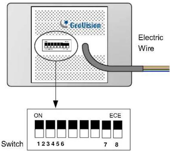
Default settings are all ON.
■ SW 1 Beeper Control: The default mode for the Beeper Control is the internal control. When the setting is "On", the Reader is sounded after a card is read. When the setting is "Off", the Beeper is controlled externally. You can use the external beeper control line to activate the beeper.
■ SW2-SW3 Green/Red LED Control: The default mode for the Green/Red LED Control is the internal control. The LED is normally red. When a card is read, the LED flashes green. When the setting is “Off”, the Green/Red LED is controlled externally. The external control lines can then be used to operate the LEDs.
■ SW4 Master/Slave: The switch is used to select the Reader's communication interface. When the setting is "On", the Reader is controlled by Wiegand signal. When the setting is "Off", the Reader is for RS-485 signal.
■ SW5-SW7 ID Setting: Switch 5 to switch 7 is used to set the Reader's ID for wiring in a daisy chain.
■ SW8 RS-485 Terminal Resistor: When the setting is "On," a 120-ohm resistor is connected between RS-485+ and RS-485-. This setting is used in the last device when multiple RS-485 devices are connected together.
Note: After changing the dip switch settings, the unit must be reset by powering down then up again before the new switch setting will take effect.
1.2.3 Define the ID of GV-SR1251
Up to 8 readers can be connected to GV-AS Controller via a single RS-485 interface. To create a daisy chain connection, use the Setup AP to define each reader's ID number.
- Install and download the Setup AP. For details, see 2.4 Install GV-R/RK/DFR Setup AP.
- Run GV-R/RK/DFR Setup AP.
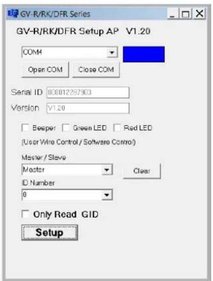
- Select the COM port that is connected to the reader and click Open COM. The red square next to the COM port box should change to blue to indicate the COM port is correct.
- Select an ID number for the reader. The ID number ranges from 0 to 7.
- Click Setup. The serial number and firmware version of the reader are automatically detected. The settings are sent to the reader.
Note:
- To define the ID number of GV-Reader1251 / 1352 V2, use the switches at the back of the reader.
- GV-SR1251 only reads UID (Unique Identifier). Therefore, the Only Read GID option in the GV-R/RK/DFR Setup AP is not functional for GV-SR1251.
1.3 Connect the Reader to GV-AS Controller
GV-Reader1251 / 1352 V2 / SR1251 is compatible with any standard access controllers. The following diagrams illustrate how to connect GV-Reader1251 / 1352 V2 / SR1251 to GV-AS Controller through Wiegand or RS-485 interface, and how to connect GV-Reader1251 / 1352 V2 / SR1251 to third-party access controllers and GV-DVR/NVR.
For GV-Reader1251 / 1352 V2, after you wire the connection between the reader and the access controller, ensure that related switch settings on GV-Reader1251 / 1352 V2 are configured correctly.
Note: Each reader consumes 60 mA of power. The total power consumption of the output devices and readers connected to GV-AS Controller must be under 2.5A (for GV-CS1320), 3A (for GV-AS1620, GV-AS210 / 2110 / 2120), 3.5A (for GV-AS410 / 4110) or 5A (for GV-AS810 / 8110). Connect an external power supply if the power supplied from GV-AS Controller is insufficient.
1.3.1 Connect through Wiegand Interface
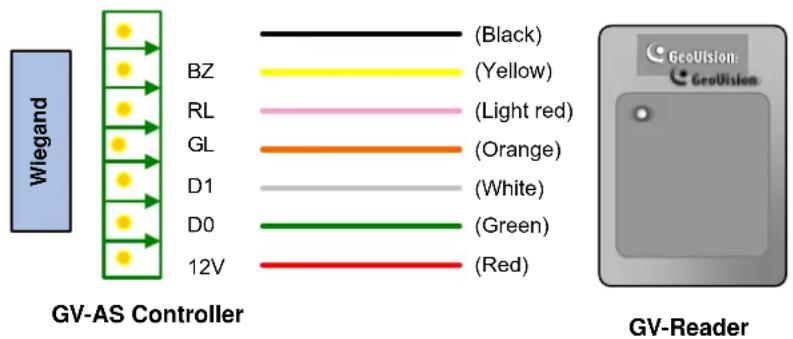
- Switch Setting for Wiegand Connection (GV-Reader1251 / 1352 V2 only)
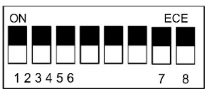
SW4 must be turned ON.
1.3.2 Connect through RS-485 Interface
Multiple readers can be connected to GV-AS Controller through a single RS-485 interface.
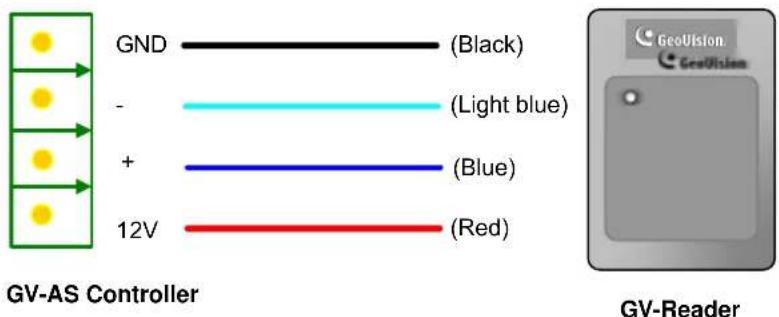
- Switch Settings for RS-485 Connection (GV-Reader1251 / 1352 V2 only)
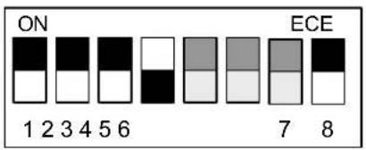
SW4 must be turned OFF.
- Switch Settings for Multiple GV-Readers (RS-485) (GV-Reader1251 / 1352 V2 only) When connecting multiple readers to GV-AS Controller, turn SW8 on the last connected GV-Reader to ON. Make sure to define the ID of each reader using SW5 to SW7 first.
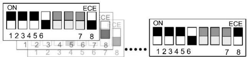
After configuring the switch settings of GV-Reader1251 / 1352 V2 or defining the ID number of GV-SR1251 using GV-R/RK/DFR Setup AP, you need to specify which door each reader controls on the Web interface of GV-AS Controller.
- On the controller's Web interface, select Extended Reader. This page appears.
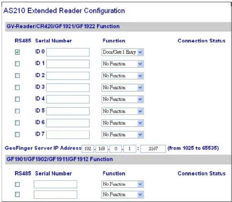
- If the readers are connected using RS-485, select the RS485 checkbox in front of the ID number. The ID number must match the ID you configured using SW5 – SW7 (for GV-Reader1251 / 1352 V2) or GV-R/RK/DFR Setup AP (for GV-SR1251).
- Leave the serial number field blank.
- Select a door/gate for the reader under Function. Click Submit.
1.3.3 Connect to GV-DVR/NVR and Third-Party Controllers
GV-Reader1251 / 1352 V2 / SR1251 is compatible with third-party access controllers. With its compatibility, you can also add a GV-DVR/NVR to this connection to empower your management.
After connecting GV-Reader1251 / 1352 V2 / SR1251 to the access controller through the Wiegand interface, connect the reader to GV-DVR/NVR via GV-COM, GV-Hub or GV-NET/IO Card V3.1.
Note: GV-Reader1251 / 1352 V2 / SR1251 is not compatible with the GV-NET Card and the GV-NET/IO Card of versions earlier than V3.
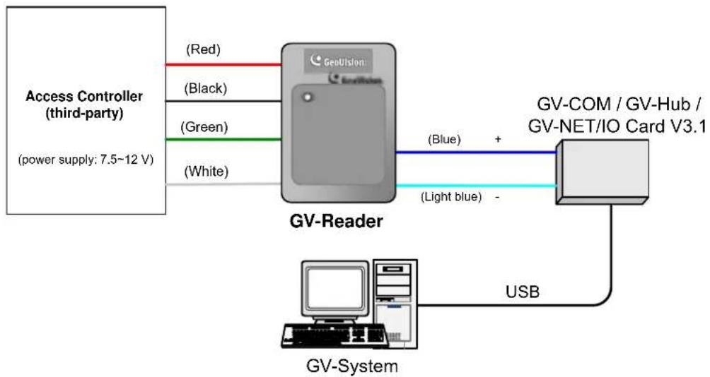
flowchart
graph TD
    A["Access Controller (third-party)<br>(power supply: 7.5~12 V)"] -->|Red| B["GV-Reader"]
    A -->|Black| B
    A -->|Green| B
    A -->|White| B
    B -->|Blue| C["GV-COM / GV-Hub / GV-NET/IO Card V3.1"]
    B -->|Light blue| C
    C -->|USB| D["GV-System"]
- Switch Setting (GV-Reader1251 / 1352 V2 only)
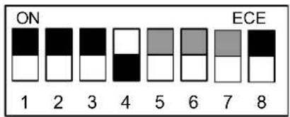
SW4 must be turned OFF.
1.4 Overlay Card Numbers on GV-DVR/NVR Live View
You can overlay card numbers recognized at GV-Reader1251 / 1352 V2 / SR1251 onto a camera channel on GV-DVR/NVR. To overlay card numbers on GV-DVR/NVR channels, connect the reader to GV-DVR/NVR through a RS-485 / USB converter (e.g. GV-COM, GV-Hub or GV-NET/IO Card V3.1) as illustrated below. For details, see 2.5 Overlay Card Numbers on GV-DVR/NVR Live View.
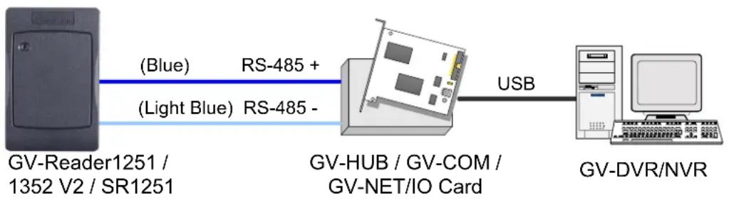
flowchart
graph LR
    A["GV-Reader1251 / 1352 V2 / SR1251"] -->|Blue| B["RS-485 +"]
    A -->|Light Blue| C["RS-485 -"]
    B --> D["GV-HUB / GV-COM / GV-NET/IO Card"]
    C --> D
    D -->|USB| E["GV-DVR/NVR"]
Note:
- For GV-Reader1251 / 1352 V2, you need to define the ID number and set the reader to slave by configuring the switch settings. For details, see 1.2.2 Switch Settings of GV-Reader1251 / 1352 V2.
- For GV-SR1251, you need to define the ID number and set the reader to Slave using GV-R/RK/DFR Setup AP. For details, see 2.5.1 Define the ID and Set the Reader to Slave.
1.5 Control the Beeper and LED
You can configure GV-AS Controller (AS210 / 2110 / 2120 / 410 / 4110 / 810 / 8110) to control the reader's beeper or LED externally. Through the controller's Web interface, you can configure the controller to activate the reader's red LED, green LED, or beeper in response to a specific alert event.
- For GV-SR1251, enable external controls of the reader's beeper and LED by using the GV-R/RK/DFR Setup AP. For details, see 2.6.1 Enable External Control on the Reader.
- For GV-Reader1251 / 1352 V2, enable external controls of the reader's beeper and LED by configuring the switch settings. For details, see 1.2.2 Switch Settings of GV-Reader1251 / 1352 V2.
- Wire the beeper, Red LED or Green LED from the reader to the controller. For details, see 2.6.2 Connect the Beeper and LED.
- Specify the beeper and LED settings for each door through the controller's Web interface. For details, see 2.6.3 Set the Beeper and LED for Each Door/Gate.
Note: GV-AS1620 can also externally control the reader's LED and beeper for access granted and denied. For details, see GV-AS1620 User's Manual.
IMPORTANT: When GV-RK1352 / R1352 / DFR1352 / SR1251 is connected to a controller via an RS-485 connection, external control of the LED and beeper is not supported.
1.6 Specifications
| GV-Reader1251 | GV-SR1251 | GV-Reader1352 (V2) | |
| CPU | 8-bit microprocessor | ||
| Wiegand Interface | Wiegand 26 bits, distance 30 m (98.43 ft) with GV-AS210 / 410 / 810; distance 100 m (328.1 ft) with GV-AS2110 / 2120 / 4110 / 8110, GV-AS1620 | Wiegand 26 / 34 bits, distance 30 m (98.43 ft) | |
| Power Source | DC 7.5~12V | ||
| Power Consumption | 60 mA | ||
| LED | Red, Green LED | Red, Green, Blue LED | Red, Green LED |
| Audio | Buzzer | ||
| Frequency | 125 kHz | 13.56 MHz ISO 14443A | |
| RS-485 | 9,600 bps, distance 600 m (1968.50 ft) | ||
| Color | Gray | ||
| Operating Temperature | -35 °C ~ 65 °C (-31 °F ~ 149 °F) | ||
| Operating Humidity | 10 ~90% RH (non-condensing) | ||
| Dimensions (W x H x D) | 75 (W) x 115 (H) x 15 (T) mm, with enclosure 35 (T) mm 3 (W) x 4.5 (H) x 0.6 (T) in, with enclosure 1.38 (T) in | ||
| Weight | 150 g / 0.33 lb | 125 g / 0.27 lb | 150 g / 0.33 lb |
| Ingress Protection | IP54 | IP66 | IP54 |
| Certification | CE, FCC, RoHS | ||
For the number of readers supported by a variety of GeoVision controllers, see the compatibility table.
Chapter 2 GV-RK1352 / R1352 / DFR1352
Card readers GV-RK1352 / R1352 / DFR1352 are able to recognize access cards. The keypad on GV-RK1352 allows it to recognize PIN codes. GV-DFR1352 is intended for installation on the door frame.
Featured with the Wiegand and RS-485 outputs, the readers can be connected to any standard access control system. They are protected by a weather sealed and IP66 compliant housing for outdoor use.
2.1 Packing List
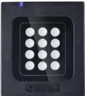
GV-RK1352
natural_image
Close-up of a black square electronic device with a grid of circular components, labeled 'GeoUiston' at the bottom (no other text or symbols visible)- GV-RK1352 Card Reader
- Screw x 2
- Screw Anchor x 2
- Front Cover Plate x 1
- Software CD
- Installation Guide
- Warranty Card
GV-R1352

natural_image
Solid dark gray surface with a small blue dot at the top left corner (no text or symbols)- GV-R1352 Card Reader
- Screw x 3
- Screw Anchor x 2
- Security Torx
- Software CD
- Installation Guide
- Warranty Card
GV-DFR1352
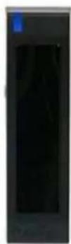
- GV-DFR1352 Card Reader
- Screw x 2
- Screw Anchor x 2
- Front Cover Plate x 2
- Software CD
- Installation Guide
- Warranty Card
2.2 Physical Descriptions
2.2.1 Electric Wire
GV-RK1352
| Wire Color | Function |
| Red | DC 7.5 ~ 12 V |
| Black | GND |
| Yellow | Beeper |
| Orange | Green LED |
| Light Red | Red LED |
| Green | Wiegand Data 0 |
| White | Wiegand Data 1 |
| Blue | RS-485 + |
| Light Blue | RS-485 - |
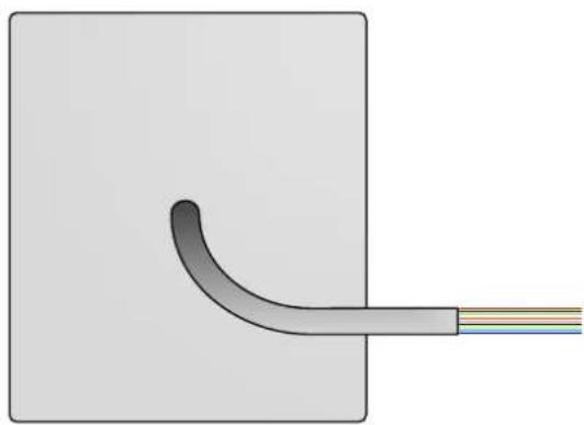
natural_image
Diagram of a curved pipe or tube with a connecting rod, shown against a plain background (no text or symbols)Rear View
GV-R1352
| Wire Color | Function |
| Red | DC 7.5 ~ 12V |
| Black | GND |
| Yellow | Beeper |
| Orange | Green LED |
| Light Red | Red LED |
| Green | Wiegand Data 0 |
| White | Wiegand Data 1 |
| Blue | RS-485 + |
| Light Blue | RS-485 - |
| Gray | N/A |
| Purple | N/A |
| Brown | N/A |

natural_image
Diagram of a cable connector with a curved cable and wire, no text or symbols presentRear View
GV-DFR1352
| Wire Color | Function |
| Red | DC 7.5 ~ 12V |
| Black | GND |
| Yellow | Beeper |
| Orange | Green LED |
| Light Red | Red LED |
| Green | Wiegand Data 0 |
| White | Wiegand Data 1 |
| Blue | RS-485 + |
| Light Blue | RS-485 - |
| Gray | N/A |
| Purple | N/A |
| Brown | N/A |
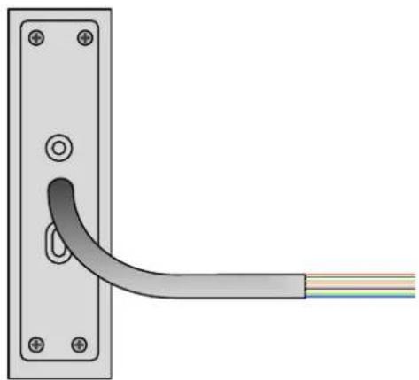
natural_image
Diagram of a cable being inserted into a wall-mounted bracket, showing wire routing (no text or symbols)Rear View
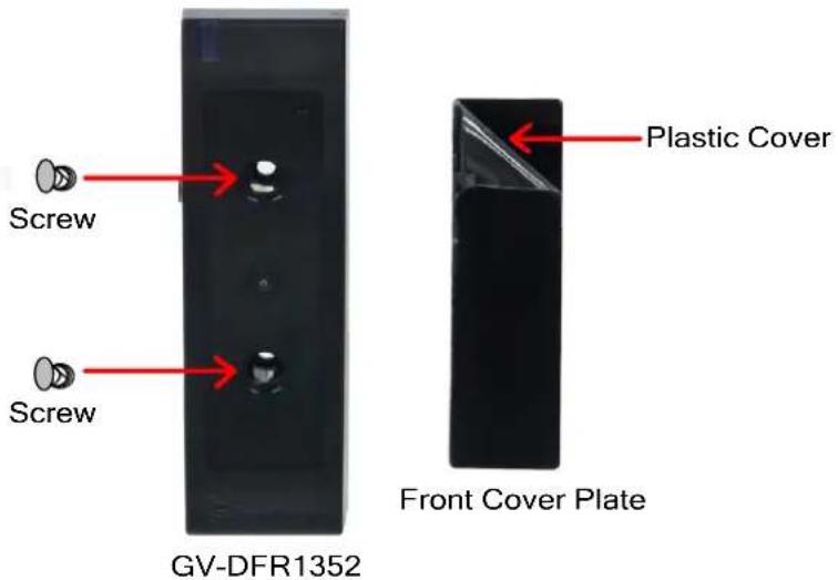
Install the GV-DFR1352 to the door frame using the supplied screws and screw anchors. Before placing and sticking the front cover plate to the GV-DFR1352, remove the Plastic Cover to prevent scratches to the cover after installed.
2.2.2 Keypad (GV-RK1352 Only)
When using the reader, you can enter the door's Common Password or the card's PIN code on the keypad to gain access. The access mode is set in GV-ASManager (software).
- 0\~9 Number Keys: Press the number keys to enter a PIN or password.
-
Key: Press the # key to confirm an entry.
- * Key: Press the * key to cancel an entry.
IMPORTANT: The Card and PIN Code mode requires users to enter the card's PIN code, press the # key to confirm the code, and then present the card to gain access.
2.2.3 LED and Beeper
In standby mode, the LED is blue. When a card is read, the LED flashes green and the beeper beeps once.
The reader comes with external control wires for Green LED, Red LED and Beeper. You can connect these control wires to GV-AS Controller to change the default settings of the LED and beeper. For details on how to configure the settings, see 2.6 Control the Beeper and LED.
Note:
- The following controllers support external control of the LED and beeper: GV-AS210 / 2110 / 2120 / 410 / 4110 / 810 / 8110, and GV-AS1620.
- The LED and beeper functions are currently unavailable for GV-RK1352 when it is accessed by the built-in keypad.
IMPORTANT: When GV-RK1352 / R1352 / DFR1352 / SR1251 is connected to a controller via an RS-485 connection, external control of the LED and beeper is not supported.
2.3 Connect the Reader to GV-AS Controller
You can connect the readers to GV-AS Controllers through Wiegand or RS-485 interface. Note that the connection between the reader and GV-AS Controller varies among controller models. For the number of readers supported by a variety of GeoVision controllers, see the compatibility table.
Note:
- GV-RK1352 / R1352 / DFR1352 is compatible with GV-AS100 / 1010 / 110 / 120 / 210 / 2110 / 2120 / 410 / 4110 / 810 / 8110, GV-AS1620, GV-CS1320. However, to enable the keypad function on GV-RK1352, you can only connect GV-RK1352 to the controllers through the following interfaces.
• GV-AS100 / 110 / 120: Wiegand
• GV-AS1010: RS-485
• GV-AS210 / 2110 / 2120 / 410 / 4110 / 810 / 8110: Wiegand and RS-485
• GV-AS1620: Wiegand and RS-485
• GV-CS1320: RS-485
- Each GV-RK1352 / R1352 / DFR1352 consumes 60 mA of power. The total power consumption of the output devices and readers connected to GV-AS Controller must be under 2.5A (for GV-CS1320), 3A (for GV-AS1620, GV-AS210 / 2110 / 2120), 3.5A (for GV-AS410 / 4110) or 5A (for GV-AS810 / 8110). Connect an external power supply if the power supplied from GV-AS Controller is insufficient.
2.3.1 Connect through Wiegand Interface
The following diagrams use GV-RK1352 and GV-AS810 Controller as an example. Up to eight readers can be connected to GV-AS810 Controller through the controller's Wiegand interface.
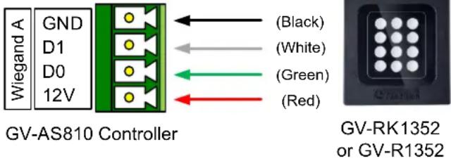
| Wire Color | Function |
| Black | GND |
| White | Wiegand Data 1 |
| Green | Wiegand Data 0 |
| Red | DC 7.5 ~ 12V |
Note: Connection through Wiegand interface is not supported for GV-AS1010.
2.3.2 Connect through RS-485 Interface
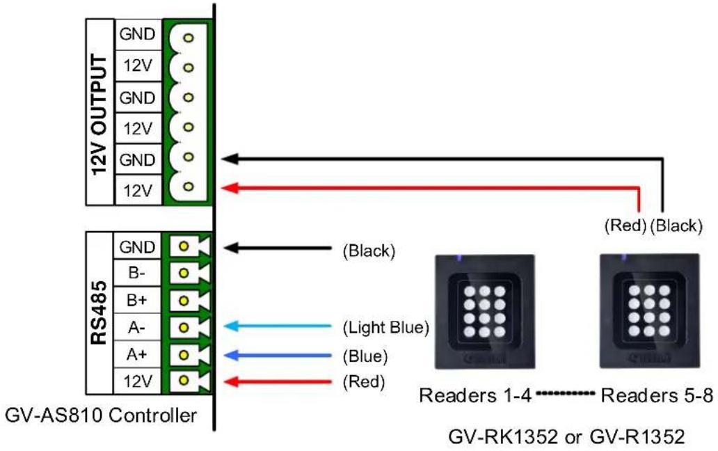
The following diagrams use GV-RK1352 and GV-AS810 Controller as an example. Up to eight readers can be connected together to the RS-485 interface on GV-AS810 Controller.
- Connecting four or less readers to GV-AS810 Controller:
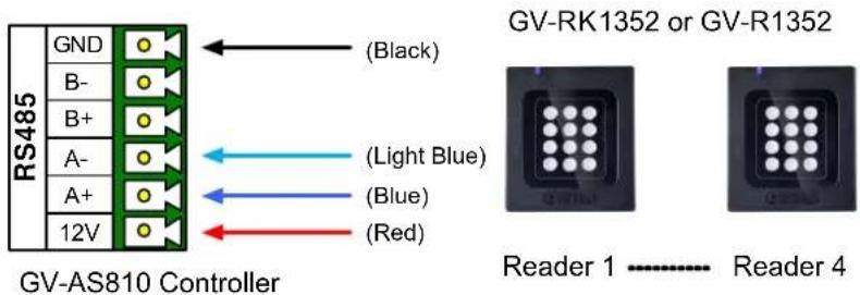
| Wire Color | Function |
| Black | GND |
| Light Blue | RS-485 - |
| Blue | RS-485 + |
| Red | DC 7.5 ~ 12V |
- Connecting five or more readers to GV-AS810 Controller:
For readers five to eight, connect the RS-485 cable to the RS-485 interface on GV-AS810 Controller and then connect the 12V power output and GND of the reader to a 12V DC power output on the controller.
2.3.3 Define Readers on GV-AS Controller Web Interface
Since multiple readers can connect to GV-AS Controller using one RS-485 interface, you need to specify which door each reader controls. This section explains how to define readers on the Web interface of GV-AS Controller. On the Web interface, you can also set the reader to read the GID or UID on your card / key fob. Note that the Web interface of different GV-AS Controller models varies.
- On the controller's Web interface, click Extended Reader. This dialog box appears.
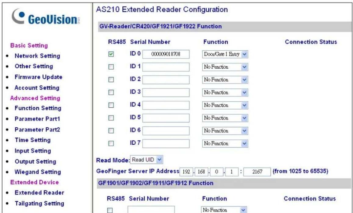
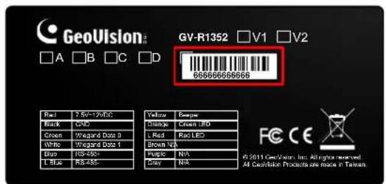
- In the GV-Reader/CR420/GF1921/GF1922 section, select the RS485 checkbox next to the ID number, and type the Serial Number which can be found on the rear panel of the reader. The ID number is assigned to the reader.
-
Select a door/gate for the reader from the Function drop-down list.
-
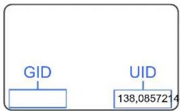
Next to Read Mode, select Read UID or Read GID to set the connected reader to read UID (Unique Identifier) or GID (GeoVision Identifier) formatted cards / key fobs.
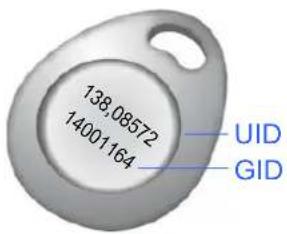
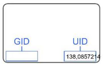
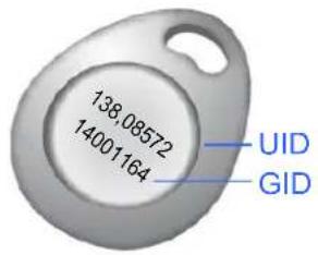
If you select Read GID, ensure there are two sets of digits on your card / key fob as shown below. If your card / key fob only has one set of digits, GID is not supported.
flowchart
graph TD
    A["GID"] --> B[" "]
    C["UID"] --> D["138,0857214"]
5. Click Submit.
Note:
- When you click Submit on the Extended Reader page of GV-AS1010 / 210 / 2110 / 2120 / 410 / 4110 / 810 / 8110, GV-AS1620, or GV-CS1320, all readers connected through RS-485 interface will reboot.
- GID format is only supported by GV-RK1352 / GV-R1352 / GV-DFR1352 (Rev. B) V1.2 or later.
- If you are using third-party cards or key fobs, you must set the reader to read UID.
2.4 Install GV-R/RK/DFR Setup AP
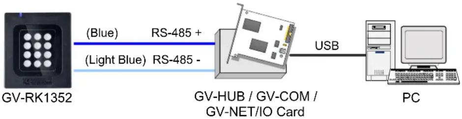
GV-R/RK/DFR Setup AP allows you to set the reader's beeper, LED, ID number, master / slave status, and whether it reads UID or GID. To use the Config AP, you need to connect the reader to a PC using a RS-485 / USB converter (e.g. GV-COM, GV-Hub or GV-NET/IO Card V3.1), as illustrated below.
flowchart
graph LR
    A["GV-RK1352"] -->|Blue (RS-485 +)| B["GV-HUB / GV-COM / GV-NET/IO Card"]
    A -->|Light Blue (RS-485 -)| B
    B -->|USB| C["PC"]
You can install the Config AP from the GeoVision website. To use a GV-COM, GV-Hub or GV-NET/IO Card V3.1, you also need to install GV-USB Device Driver to enable the device.
Downloading from GeoVision Website
- Go to the download page of GeoVision Website:
https://www.geovision.com.tw/download/product/GV-RK1352
- Download GV-RK1352 & GV-R1352 & GV-DFR1352 Config Utility.

- To download GV-USB Device Driver, go to the download page:
https://www.geovision.com.tw/download/product/GV-NET%20IO%20card%20V3.2
2.5 Overlay Card Numbers on GV-DVR/NVR Live View
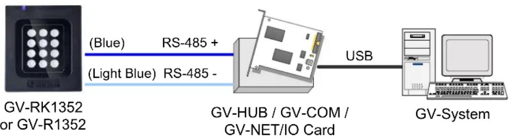
You can overlay card numbers recognized at the reader onto a camera channel on GV-DVR/NVR. To overlay card numbers on GV-DVR/NVR channels, connect the reader to GV-DVR/NVR through a RS-485 / USB converter (e.g. GV-COM, GV-Hub or GV-NET/IO Card V3.1) as illustrated below.
flowchart
graph LR
    A["GV-RK1352 or GV-R1352"] -->|Blue (RS-485 +)| B["GV-HUB / GV-COM / GV-NET/IO Card"]
    A -->|Light Blue (RS-485 -)| B
    B -->|USB| C["GV-System"]
Note: GV-RK1352 / R1352 / DFR1352 is not compatible with GV-NET Card and GV-NET/IO Card of versions earlier than V3.
To overlay card numbers on GV-DVR/NVR, follow the steps in the sections below:
- 2.5.1 Define the ID and Set the Reader to Slave: The application requires setting the reader to Slave mode. Assign a unique ID to each reader when multiple readers are connected.
● 2.5.2 Add the Reader to GV-DVR/NVR
2.5.1 Define the ID and Set the Reader to Slave
After the reader is connected to the computer of GV-DVR/NVR, use GV-R/RK/DFR Setup AP to define the ID number of the reader and set the reader to Slave.
- Run GV-R/RK/DFR Setup AP. See 2.4. Install GV-R/RK/DFR Setup AP for how to install.
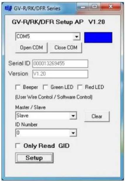
- Select the COM port that is connected to the reader and click Open COM. The red square next to the COM port box should change to blue to indicate the COM port is correct.
- Under Master / Slave, set the reader to Slave.
- Select an ID number for the reader. The ID number ranges from 0 to 7.
- Click Setup. The settings are sent to the reader. The serial number and firmware version of the reader will be automatically detected.
If you want to connect multiple readers to GV-DVR/NVR, you must assign each reader a unique ID number. Connect each reader to the computer one at a time, and then follow the steps above to create an ID number.
Note:
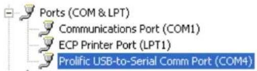
- If the COM port is incorrect, an "Error opening serial port" message will appear. To verify the COM port that is connected to the reader, go to Windows Device Manager. In the Ports (COM & LPT) field, you should see the entry for Prolific USB-to-Serial Comm Port and the COM number currently in use.
- If you are using an older version of the Config AP, you will have to manually type the serial number of the reader. The serial number is on the rear panel of the reader.
2.5.2 Add the Reader to GV-DVR/NVR
- In GV-DVR/NVR, click the Configure button, select Accessories, and select GV Wiegand Capture Device Setting. This dialog box appears.
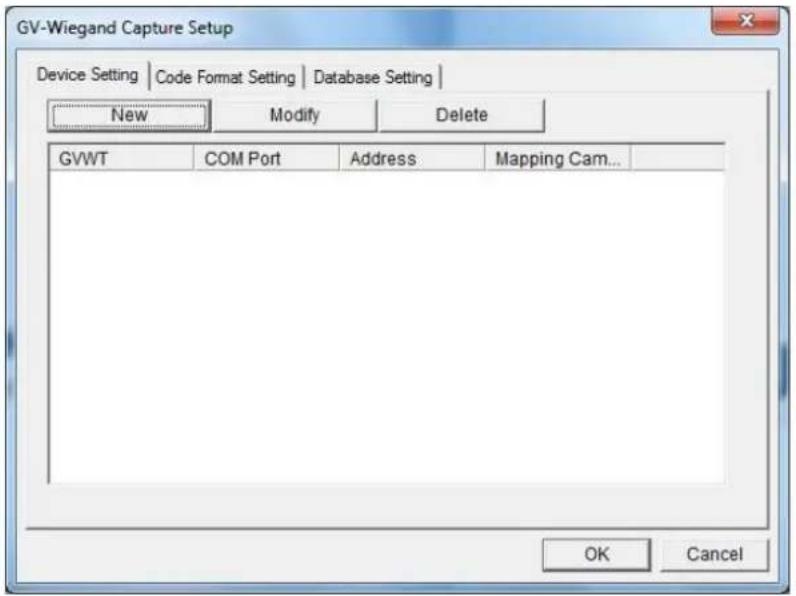
- Click the New button. This dialog box appears.
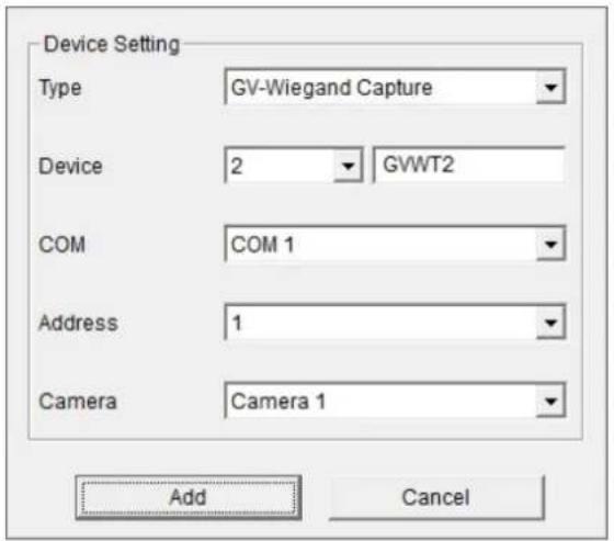
■ Type: Select GV-Wiegand Capture.
■ Device: Type a number and name to help you identify the reader.
■ COM: Select the COM port connected to the reader.
■ Address: Select the ID of the connected reader you configured with GV-R/RK/DFR Config AP.
■ Camera: Assign the reader to a channel to overlay card numbers on live view.
- Click the Add button.
2.6 Control the Beeper and LED
You can configure GV-AS Controller (AS210 / 2110 / 2120 / 410 / 4110 / 810 / 8110) to control the reader's beeper or LED externally. Through the controller's Web interface, you can configure the controller to activate the reader's red LED, green LED, or beeper in response to a specific alert event.
For this function to work, follow the steps in the three sections below:
- Enable external control of the beeper or LED by using GV-R/RK/DFR Setup AP. See section 2.6.1.
- Connect the control wires of the beeper, Red LED or Green LED to the controller. See section 2.6.2.
- Define the beeper or LED for each door through the controller's Web interface. See section 2.6.3.
Note: GV-AS1620 can also externally control the reader's LED and Beeper for access granted and denied. For details, see GV-AS1620 User's Manual.
IMPORTANT: When GV-RK1352 / R1352 / DFR1352 / SR1251 is connected to a controller via an RS-485 connection, external control of the LED and beeper is not supported.
2.6.1 Enable External Control on the Reader
To enable external control of the reader's Beeper or LED, first connect the reader to a computer through a RS-485 / USB converter (e.g. GV-COM, GV-Hub or GV-NET/IO Card V3.1) as illustrated below.
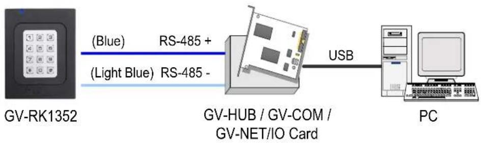
flowchart
graph LR
    A["GV-RK1352"] -->|Blue| B["RS-485 +"]
    A -->|Light Blue| C["RS-485 -"]
    B --> D["GV-HUB / GV-COM / GV-NET/IO Card"]
    C --> D
    D -->|USB| E["PC"]
- Start GV-R/RK/DFR Setup AP and select the COM port that is connected to the reader.
Note: For how to install the Config AP, see 2.4 Install GV-R/RK/DFR Setup AP. For how to identify the COM port of the reader, see Note 1, 2.5.1 Define the ID and Set the Reader to Slave.
- Click Open COM.
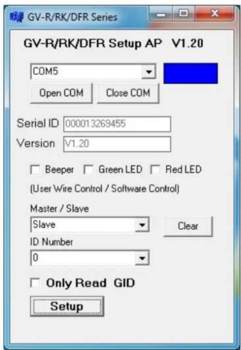
- To enable external control of Beeper or LED, select Beeper, Green LED or Red LED.
- Select Master from the Master / Slave drop-down list.
- Select an ID number for the reader. Make sure the ID number on the Config AP matches that set on the Extended Reader page of the controller's Web interface.
- Click Setup. The settings are sent to the reader. The serial number and the firmware version of the reader are automatically detected.
If you want to control multiple readers with a controller, connect each reader to the computer one at a time, and follow the above steps to enable its external control.
2.6.2 Connect the Beeper and LED
Connect the control wires of the beeper, Red LED, or Green LED to any of the outputs on the GV-AS Controller (GV-AS210 / 2110 / 2120 / 410 / 4110 / 810 / 8110).
Wiring LED to GV-AS Controller
The diagram below shows how to wire Green LED using GV-RK1352 and GV-AS810 as an example. Use the light red wire instead for Red LED.
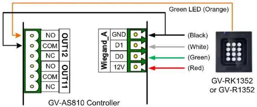
| Wire Color | Function |
| Black | GND |
| Orange | Green LED |
| Light Red | Red LED |
Wiring Beeper to GV-AS Controller
The diagram below shows how to wire the beeper using GV-RK1352 and GV-AS810 as an example.
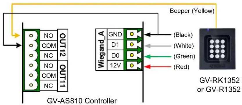
| Wire Color | Function |
| Black | GND |
| Yellow | Beeper |
After wiring the beeper, go to GV-ASManager and select the alarm conditions that will activate it. To configure the alarm conditions in GV-ASManager, right-click the controller in the device list, select Settings, and then the Door / Gate tab.
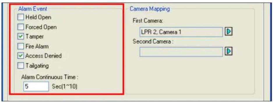
2.6.3 Set the Beeper and LED for Each Door/Gate
After connecting the wires for the beeper or LED, specify the conditions to activate the beeper or LED on the GV-AS210 / 2110 / 2120 / 410 / 4110 / 810 / 8110 Web interface.
- On the controller's Web interface, click Output Setting. This page appears.
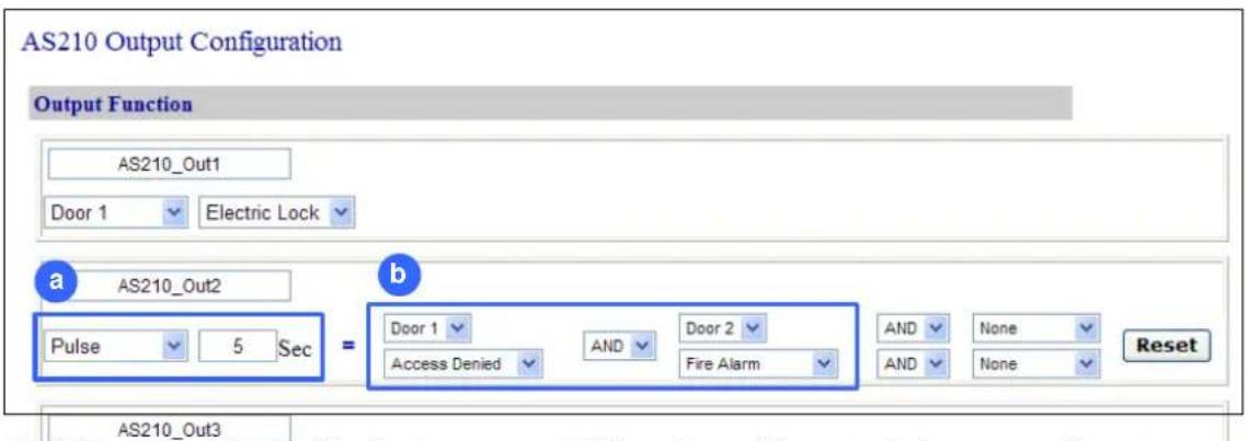
- Find the output # wired to the beeper or LED and specify up to 2 alarm conditions to activate the beeper or LED.
a. Output Type: Select Normal, Toggle or Pulse. If you select Pulse, specify the duration in seconds for the beeper or LED to be activated.
b. Output Conditions: Select the door and the alarm condition to activate the beeper or LED. Up to 2 sets of output conditions can be set.
- Click Submit.
2.7 Configure Card Identifier
The reader by default reads the UID (Unique Identifier) on access cards or key fobs. Using GV-R/RK/DFR Setup AP, you can set the reader to read GID (GeoVision Identifier) instead.
Note:
- For how to install the Config AP, see 2.4 Install GV-R/RK/DFR Setup AP. For how to identify the COM port of the reader, see Note 1, 2.5.1 Define the ID and Set the Reader to Slave.
- GID format is only supported by GV-RK1352 / GV-R1352 / GV-DFR1352 (Rev. B) V1.2 or later.
- GID is only supported by GeoVision access cards and key fobs.
1. Run GV-R/RK/DFR Setup AP.
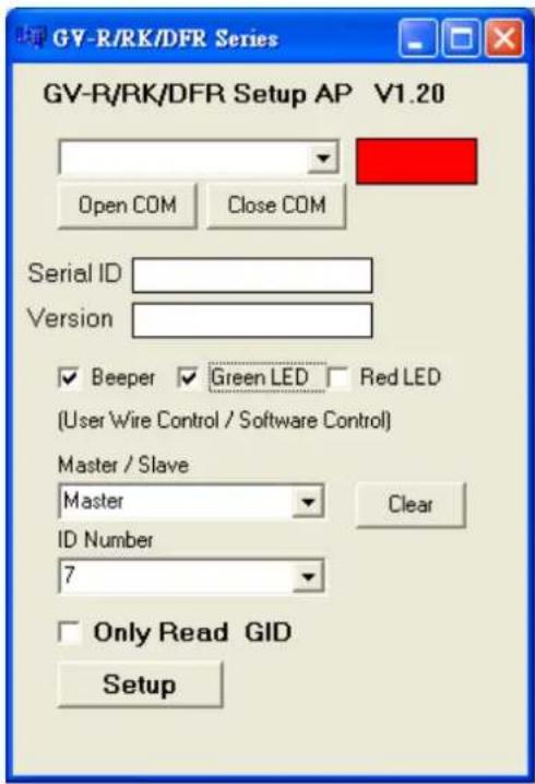
- Select the COM port that is connected to the reader and click Open COM. The red square next to the COM port box should change to blue to indicate the COM port is correct.
-
To set the reader to read GID, select Only Read GID.
-
Click Setup to apply the setting. The serial number and firmware version of the reader is automatically detected.
To use GID, make sure that your card / key fob has two sets of digits as shown below. If your card / key fob has only one set of digits, GID is not supported.
flowchart
graph TD
    A["GID"] --> B[" "]
    C["UID"] --> D["138,0857214"]
2.8 Firmware Upgrade
GeoVision periodically releases updated firmware on its website. The new firmware can be simply loaded into the reader by using Update Utility included in the Software CD.
Important Notes before You Start
Before you start updating the firmware, please read these important notes:
- While the firmware is being updated, the power supply must not be interrupted.
- Do not turn the power off within 10 minutes after the firmware is updated.
WARNING: The interruption of power supply during updating causes not only update failures but also damages to the device. In this case, please contact your sales representative and send your device back to GeoVision for repair.
To upgrade firmware:
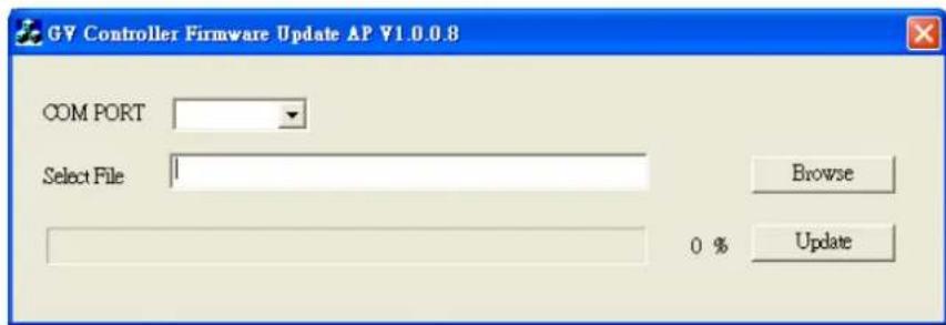
- Insert the Software CD and select Run Firmware Update Utility. This dialog box appears.
- Select the COM port of the reader.
- Click the Browse button to locate the firmware file (.bin) saved at your local computer.
- Click Update.
- The LED indicator should flash purple during the process of firmware upgrading. When the process is complete, the reader will be sounded twice and the LED indicator will change to green.
Note: You can also download the firmware upgrade utility from the link.
2.9 Specifications
| GV-RK1352 | GV-R1352 | GV-DFR1352 (Rev. B) | |
| CPU | 8-bit microprocessor | ||
| Frequency | 13.56 MHz ISO 14443A | ||
| Wiegand Interface | Wiegand 26- / 34 bits, distance 100 m (328.1ft), 24 AWG, 13V DC min., 85 °C min | ||
| RS-485 | 9,600 bps, distance 600 m (1968.50 ft), 24 AWG, 13V DC min., 85 °C min | ||
| Input Rating | 7.5V DC~12V DC, 200mA | ||
| LED | Red, Green and Blue LED | ||
| Audio | Buzzer | ||
| Reader Color | Black | ||
| Supported ID Formats | UID and GID | ||
| Operating Temperature | -35 °C ~ 66°C / -31 °F ~ 150.8 °F | ||
| Operating Humidity | 10% ~ 90% (no condensation) | ||
| Dimensions (W x H x D) | 95 x 108 x 23 mm / 3.74 x 4.25 x 0.91 in | 65.8 x 115.6 x 20.5 mm / 4.6 x 2.6 x 0.8 in | 20.9 x 105.6 x 20.5 mm / 0.8 x 4.2 x 0.8 in |
| Weight | 260 g / 0.57 lb | 120 g / 0.26 lb | 80 g / 0.17 lb |
| Ingress Protection | IP66 | ||
| Certification | CE, FCC, RoHS, UL 294, CUL | ||
For the number of readers supported by a variety of GeoVision controllers, see the compatibility table.
2.10 Accessory (GV-RK1352 and GV-R1352 Only)
Optional accessories can expand the capabilities and versatilities of your GV-RK1352 and GV-R1352. Consult our sales representative for more information.
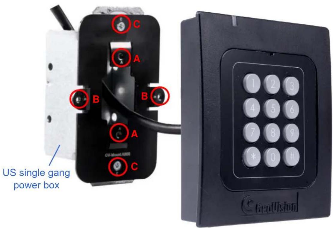
| GV-MountA900 | GV-MountA900 is a mounting plate that allows you to attach GV-RK1352 and GV-R1352 to a US single gang power box.• Dimensions: 100 x 68 mm / 3.9 x 2.7 in• Weight: 55 g / 0.12 lb |
Connecting GV-MountA900
- Screw GV-MountA900 to the US single gang power box through holes C.
- Thread the cable through GV-MountA900 and then attach the reader.
• GV-R1352: Secure through holes A
• GV-RK1352: Secure through holes B
Chapter 3 GV-RKD1352
GV-RKD1352 is a card reader with keypad, designed to read PIN codes and access cards. Featured with Wiegand and RS-485 interfaces, GV-RKD1352 can be connected to any standard access control systems. GV-RKD1352 comes with IP65 rated ingress protection suitable for indoor and outdoor applications.
3.1 Packing List
Reader x 1
Quick Start Guide x 1
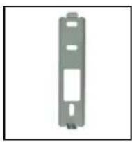
Plate x 1
Hex Key wrench x 1
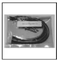
Screw x 3 Cable x 1
3.2 Compatible Products
• GV-ASManager: V5.3.3 or later
- GV-AS210 / 2110 / 2120, GV-AS810 / 8110 / 8111, GV-AS410 / 4110 / 4111: V2.41 or later (only Weigand interface supported)
• GV-AS1620: V1.05 or later
• GV-CS1320: V3.10 or later
3.3 Physical Descriptions
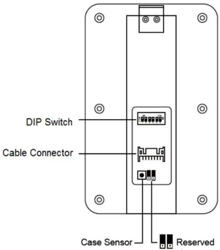
- DIP Switch: To define the reader's ID for a daisy chain connection, set up the first 5 DIP switches as listed below. DIP (6) is for card format settings.
| Node ID | Configuration |
| 0 | 00000 |
| 1 | 10000 |
| 2 | 01000 |
| 3 | 11000 |
| 4 | 00100 |
| 5 | 10100 |
| 6 | 01100 |
| 7 | 11100 |
| 8 | 00010 |
| 9 | 10010 |
| 10 | 01010 |
| 11 | 11010 |
| 12 | 00110 |
| 13 | 10110 |
| 14 | 01110 |
| 15 | 11110 |
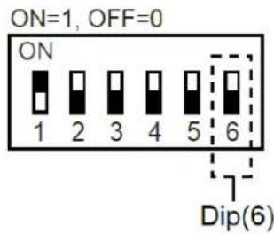
Card Identifier Setting
To only support DES-ID (for MIFAREDESFire cards) or GID (GeoVision Identifier) formatted cards, turn ON for the DIP (6).
Note:
- GV-AS DES cards contain two types of ID: UID (Unique Identifier) and DES ID. When only DES ID is required, turn on the DIP (6).
-
Every time when the DIP settings are changed, the reader needs to be restarted to apply them.
-
Cable Connector: Connect the reader to the controller based on the following pin definitions:
| Pin | Wire Color | Wiegand | RS-485 |
| 1 | Red | DC 12V | DC 12V |
| 2 | Black | Ground | Ground |
| 3 | Yellow | - | RS-485+ |
| 4 | Blue | - | RS-485- |
| 5 | Gray | (Reserved) | - |
| 6 | Pink | - | - |
| 7 | Orange & White | Ground | - |
| 8 | Orange | - | - |
| 9 | Brown | Green LED Control | - |
| 10 | Purple | Beep Control | - |
| 11 | White | Case Sensor (To Controller GND) | - |
| 12 | Green | Case Sensor (To Controller Temper Sensor) | - |
| 13 | Red & White | Wiegand Data 0 | - |
| 14 | Gray & White | Wiegand Data 1 | - |
Note: The RS-485 interface supports either RS-485 or OSDP communication but not both at the same time.
3.4 Installation
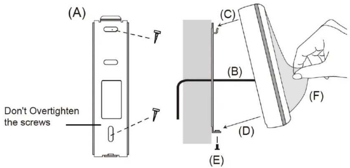
Before the hardware installation, refer to Physical Descriptions for the Node ID settings.
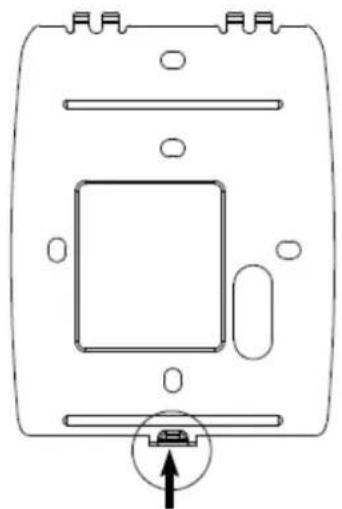
A. Mount the backplate onto the wall or back box (US standard 120 type). Note DO NOT overtighten the backplate screws during installation to prevent distortion.
B. Connect the wires in accordance with the Wiring Note below.
C. Make sure the backplate and the upper cover guide of the reader are aligned.
D. Install the upper cover of the reader to the backplate.
E. Fasten the screw onto the bottom of the reader.
F. Tear off the protective film.
Wiring Note:
- Use minimum 22 AWG double-shielded aluminum mylar foil twisted pair cable for the connection between the reader and the controller.
- In order to reduce long distance noise, the isolated net of transmission cable should connect to both ends of device ground.
- The distance between two readers should be over 30 cm to prevent radio frequency interference from each other.
- Mounting the reader around metal could affect read range. Metal of any type around the reader should be avoided while mounting.
- The distance between the reader and the controller should not exceed 30 meters (98 ft) (for Wiegand model only).
- For optimum read range, use DC Linear power adaptor for the reader's power supply.
-
In order to ensure the reader's normal operation, input voltage should be 12V±10%.
-
If the reader is installed in an open area or highly humid environment, it is recommended to protect the reader with an external shielding cover.
- RS-485 communication baud rate is 9600.
3.5 Keypad
When using the reader, you can enter the door's Common Password or the card's PIN code on the keypad to gain access. The access mode is set in GV-ASManager (software).
- 0\~9 Number Keys: Press the number keys to enter a PIN code or password.
● E Key: Press the E key to confirm an entry.
● C Key: Press the C key to cancel an entry.
IMPORTANT: The Card and PIN Code mode requires users to enter the card's PIN code, press the E key to confirm the code, and then present the card to gain access.
3.6 LED Status and Beeper
The reader has the following LED status and beeper actions by default:
| Condition | Wiegand | RS-485 |
| Standby | Constant Red | No light |
| Access Denied | Beep once (No LED) | Flash Red momentarily + Beep three times |
| Access Granted | Beep once (No LED) | Flash Green momentarily + Beep twice |
The reader includes external control wires for the Green LED and Beeper for Wiegand connection. You can change the default settings of the LED and Beeper by connecting these control wires to the GV-AS Controller.
3.7 Firmware Upgrade
GeoVision periodically updates its website with the latest firmware. Using the provided tool, the new firmware can be easily installed on the reader.
First, prepare a RS-485 / USB converter, and connect the reader to a PC as illustrated below.

flowchart
graph LR
    A["DC 12V"] --> B["GV-RKD1352"]
    B --> C["(Yellow) RS-485 +"]
    B --> D["(Blue) RS-485 -"]
    C --> E["RS-485 / USB Converter"]
    D --> E
    E --> F["USB"]
    F --> G["PC"]
To upgrade firmware:
- Download the Firmware Upgrade Tool from our website to the PC.
- Run the Tool. This dialog box appears.
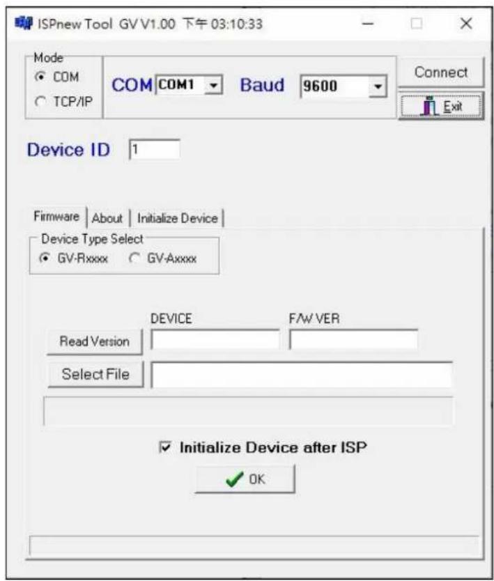
- Select the COM port used by the reader in the PC, set the Baud rate to 9600, and click Connect.
-
Make sure the Device ID is the same as the reader's current ID. If not, revise the ID.
-
Click Read Version. The reader's name and firmware version should be displayed.
- Click Select File to locate the firmware file.
- Click Initialize Device after ISP, and then OK to start firmware upgrade.
- After firmware upgrade, the message "Are you sure you want to the device to initialize?" appears. Click Yes.
- After initialized, the reader flashes green once with beeping five times, and then LED turns to red. Click Exit to close the tool.
Note:
- For the Device ID, check switch settings at the rear panel of the reader. See 3.3 Physical Descriptions.
- If firmware upgrade fails due to a loose wire connection and the reader flashes green constantly after reconnecting to power, do the following:
A. Rewire the reader properly.
B. Set the Baud rate to 19200 in the ISP New Tool.
C. Click Read Version. The FW version should display V0.00.
D. Select the firmware file.
E. Click Initialize Device after ISP, and then OK to start firmware upgrade.
After Step E, GV-RKD1352 has been updated but not initialized yet. To initialize the reader, follow the steps below:
F. Set the Baud rate to 9600 in the ISP New Tool.
G. Click Initialize Device after ISP, and then OK to start initialization.
3.8 Specifications
For details, please see the datasheet.
For the number of readers supported by a variety of GeoVision controllers, see the compatibility table.
Chapter 4 GV-R1355
The card reader GV-R1355, which has Wiegand and RS-485 interfaces, can be integrated into any standard access control system. GV-R1355 has IP66 ingress protection, making it suitable for both indoor and outdoor applications.
4.1 Packing List
- Reader
- Screw x 3
- Quick Start Guide
4.2 Compatible Products
• GV-ASManager: V5.3.3 or later
- GV-AS210 / 2110 / 2120, GV-AS810 / 8110 / 8111, GV-AS410 / 4110 / 4111: V2.41 or later (only Weigand interface supported)
• GV-AS1620: V1.05 or later
• GV-CS1320: V3.10 or later
4.3 Physical Descriptions
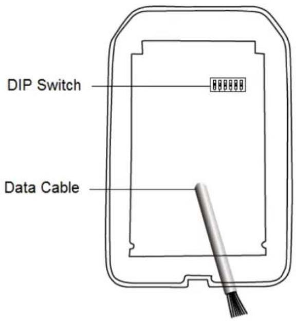
- DIP Switch: To define the reader's ID for a daisy chain connection, set up the first 5 DIP switches as listed below. DIP (6) is for card format settings.
| Node ID | Configuration |
| 0 | 00000 |
| 1 | 10000 |
| 2 | 01000 |
| 3 | 11000 |
| 4 | 00100 |
| 5 | 10100 |
| 6 | 01100 |
| 7 | 11100 |
| 8 | 00010 |
| 9 | 10010 |
| 10 | 01010 |
| 11 | 11010 |
| 12 | 00110 |
| 13 | 10110 |
| 14 | 01110 |
| 15 | 11110 |
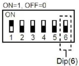
Card Identifier Setting
To set the reader to only read DES-ID (for MIFAREDESFire cards) or GID (GeoVision Identifier) formatted cards, turn ON for the DIP (6).
Note:
- GV-AS DES cards contain two types of ID: UID (Unique Identifier) and DES-ID. When only DES-ID is required, turn on the DIP (6).
- Every time when the DIP settings are changed, the reader needs to be restarted to apply them.
- Cable Connector: Connect the reader to the controller based on the following pin definitions:
| Pin | Wire Color | Wiegand | RS-485 |
| 1 | Red | DC 12V | DC 12V |
| 2 | Black | Ground | Ground |
| 3 | Yellow | - | RS-485+ |
| 4 | Blue | - | RS-485- |
| 5 | Purple | Beep Control | |
| 6 | Brown | Green LED Control | |
| 7 | Green | - | |
| 8 | White | - | |
| 9 | Light Blue | Wiegand Data 0 | |
| 10 | Gray | Wiegand Data 1 |
Note: The RS-485 interface supports either RS-485 or OSDP communication but not both at the same time.
4.4 Installation
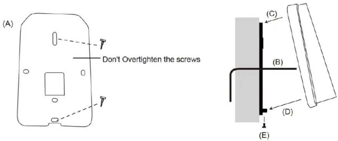
Before the hardware installation, refer to Physical Descriptions for the Node ID settings.
A. Mount the backplate onto the wall or back box (US standard 120 type). Note DO NOT overtighten the backplate screws during installation to prevent distortion.
B. Connect the wires in accordance with the wiring notes below.
C. Make sure the backplate and the upper cover guide of the reader are aligned.
D. Install the upper cover of the reader to the backplate.
E. Fasten the screw onto the bottom of the reader.
Wiring Note:
- Use minimum 22 AWG double-shielded aluminum mylar foil twisted pair cable for the connection between the reader and the controller.
- In order to reduce long distance noise, the isolated net of transmission cable should connect to both ends of device ground.
- The distance between two readers should be over 30 cm to prevent radio frequency interference from each other.
- Mounting the reader around metal could affect read range. Metal of any type around the reader should be avoided while mounting.
- The distance between the reader and the controller should not exceed 30 meters (98 ft) (for Wiegand model only).
- For optimum read range, use DC Linear power adaptor for the reader's power supply.
- In order to ensure the reader's normal operation, input voltage should be 12V±10%.
- If the reader is installed in an open area or highly humid environment, it is recommended to protect the reader with an external shielding cover.
- RS-485 communication baud rate is 9600.
4.5 LED Status and Beeper
The reader has the following LED status and beeper actions by default:
| Condition | Wiegand | RS-485 |
| Standby | Constant Red | No light |
| Access Denied | Beep once (No LED) | Flash Red momentarily + Beep three times |
| Access Granted | Beep once (No LED) | Flash Green momentarily + Beep twice |
The reader includes external control wires for the Green LED and Beeper for Wiegand connection. You can change the default settings of the LED and Beeper by connecting these control wires to the GV-AS Controller.
4.6 Firmware Upgrade
GeoVision will periodically release the updated firmware on the website. The new firmware can be simply loaded into the reader by using the tool provided. For how to upgrade the firmware, see 3.7 Firmware Upgrade.
4.7 Specifications
For details, please see the datasheet.
For the number of readers supported by a variety of GeoVision controllers, see the compatibility table.
Chapter 5 GV-RKR1355
GV-RKR1355 is a scramble keypad reader with numeric keys displayed in random order after cards are swiped or PINs are entered. Featured with Wiegand and RS-485 interfaces, GV-RKR1355 can be integrated to any standard access control systems.
5.1 Packing List
- GV-RKR1355
- Screw x 4
- Cable
- Quick Start Guide
5.2 Compatible Products
• GV-ASManager: V5.3.3 or later
- GV-AS210 / 2110 / 2120, GV-AS810 / 8110 / 8111, GV-AS410 / 4110 / 4111: V2.41 or later (only Weigand interface supported)
• GV-AS1620: V1.05 or later
• GV-CS1320: V3.10 or later
5.3 Physical Descriptions
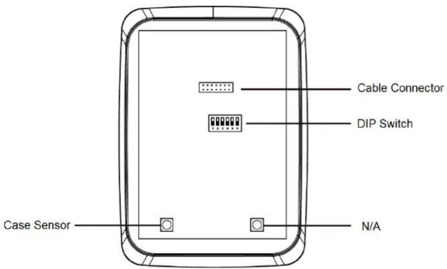
- DIP Switch: To define the reader's ID for a daisy chain connection, set up the first 5 DIP switches as listed below. DIP (6) is for card format settings.
| Node ID | Configuration |
| 0 | 00000 |
| 1 | 10000 |
| 2 | 01000 |
| 3 | 11000 |
| 4 | 00100 |
| 5 | 10100 |
| 6 | 01100 |
| 7 | 11100 |
| 8 | 00010 |
| 9 | 10010 |
| 10 | 01010 |
| 11 | 11010 |
| 12 | 00110 |
| 13 | 10110 |
| 14 | 01110 |
| 15 | 11110 |
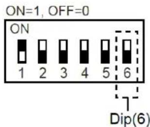
Card Identifier Setting
To set the reader to only read DES-ID (for MIFARE DESFire cards) or GID (GeoVision Identifier) formatted cards, turn ON for the DIP (6).
Note:
- GV-AS DES cards contain two types of ID: UID (Unique Identifier) and DES-ID. When only DES-ID is required, turn on the DIP (6).
- Every time when the DIP settings are changed, the reader needs to be restarted to apply them.
- Cable Connector: Connect the reader to the controller based on the following pin definitions:
| Pin | Wire Color | Wiegand | RS-485 |
| 1 | Red | DC 12V | DC 12V |
| 2 | Black | Ground | Ground |
| 3 | Yellow | - | RS-485+ |
| 4 | Blue | - | RS-485- |
| 5 | Gray | - | - |
| 6 | Pink | - | - |
| 7 | Orange & White | Ground | - |
| 8 | Orange | - | - |
| 9 | Brown | Green LED Control | - |
| 10 | Purple | Beep Control | - |
| 11 | White | Case Sensor (To Controller GND) | - |
| 12 | Green | Case Sensor (To Controller Temper Sensor) | - |
| 13 | Red & White | Wiegand Data 0 | - |
| 14 | Gray & White | Wiegand Data 1 | - |
Note: The RS-485 interface supports either RS-485 or OSDP communication but not both at the same time.
5.4 Installation
(A)
(E)
Before the hardware installation, refer to Physical Descriptions for the Node ID settings.
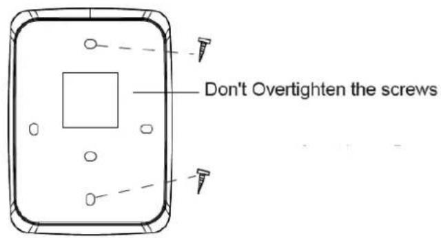
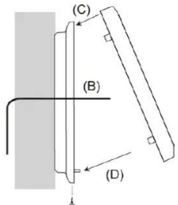
A. Mount the backplate onto the wall or back box (US standard 120 type). Note DO NOT overtighten the backplate screws during installation to prevent distortion.
B. Connect the wires in accordance with the Wiring Note below.
C. Make sure the backplate and the upper cover guide of the reader are aligned.
D. Install the upper cover of the reader to the backplate.
E. Fasten the screw onto the bottom of the reader.
Wiring Note:
- Use minimum 22 AWG double-shielded aluminum mylar foil twisted pair cable for the connection between the reader and the controller.
- In order to reduce long distance noise, the isolated net of transmission cable should connect to both ends of device ground.
- The distance between two readers should be over 30 cm to prevent radio frequency interference from each other.
- Mounting the reader around metal could affect read range. Metal of any type around the reader should be avoided while mounting.
- The distance between the reader and the controller should not exceed 30 meters (98 ft) (for Wiegand model only).
- For optimum read range, use DC Linear power adaptor for the reader's power supply.
- In order to ensure the reader's normal operation, input voltage should be 12V±10%.
- If the reader is installed in an open area or highly humid environment, it is recommended to protect the reader with an external shielding cover.
- RS-485 communication baud rate is 9600.
5.5 Keypad
When using the reader, you can enter the door's Common Password or the card's PIN code on the keypad to gain access. The access mode is set in GV-ASManager (software).
- 0\~9 Number Keys: Press the number keys to enter a PIN code or password.
● E Key: Press the E key to confirm an entry.
● C Key: Press the C key to cancel an entry.
IMPORTANT: The Card and PIN Code mode requires users to enter the card's PIN code, press the E key to confirm the code, and then present a card to gain access.
5.6 LED Status and Beeper
The reader has the following LED status and beeper actions by default:
| Condition | Wiegand | RS-485 |
| Standby | Constant Red | No light |
| Access Denied | Beep once (No LED) | Flash Red momentarily + Beep three times |
| Access Granted | Beep once (No LED) | Flash Green momentarily + Beep twice |
The reader includes external control wires for the Green LED and Beeper for Wiegand connection. You can change the default settings of the LED and Beeper by connecting these control wires to the GV-AS Controller.
5.7 Firmware Upgrade
GeoVision periodically updates its website with the latest firmware. Using the provided tool, the new firmware can be easily installed on the reader. For how to upgrade the firmware, see 3.7 Firmware Upgrade.
5.8 Specifications
For details, please see the datasheet.
For the number of readers supported by a variety of GeoVision controllers, see the compatibility table.
Chapter 6 GV-RKV1355
GV-RKV1355 is a vandal-resistant keypad reader capable of reading PIN codes and access cards. To successfully resist vandalism, the reader's case is made of zina alloy, making it suited for high-security locations such as banks and prisons. Featured with Wiegand and RS-485 interfaces, GV-RKV1355 can be integrated to any standard access control systems. Furthermore, the reader complies with IP66 ingress protection, making it perfect for both indoor and outdoor applications.
6.1 Packing List
- GV-RKV1355
- Plate
- Hex Key Wrench
- Screw x 3
- Quick Start Guide
6.2 Compatible Products
• GV-ASManager: V5.3.3 or later
- GV-AS210 / 2110 / 2120, GV-AS810 / 8110 / 8111, GV-AS410 / 4110 / 4111: V2.41 or later (only Weigand interface supported)
• GV-AS1620: V1.05 or later
• GV-CS1320: V3.10 or later
6.3 Physical Descriptions
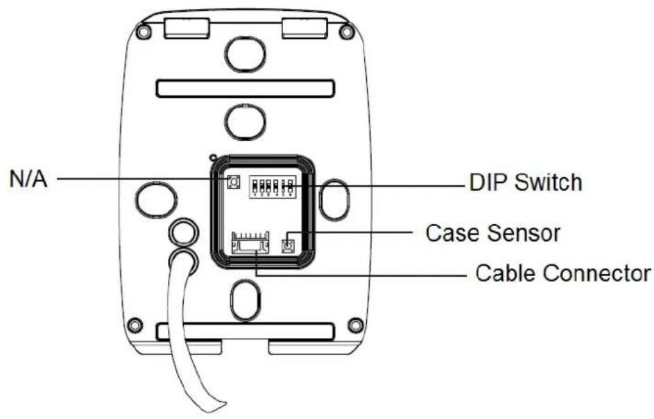
- DIP Switch: To define the reader's ID for a daisy chain connection, set up the first 5 DIP switches as listed below. DIP (6) is for card format settings.
| Node ID | Configuration |
| 0 | 00000 |
| 1 | 10000 |
| 2 | 01000 |
| 3 | 11000 |
| 4 | 00100 |
| 5 | 10100 |
| 6 | 01100 |
| 7 | 11100 |
| 8 | 00010 |
| 9 | 10010 |
| 10 | 01010 |
| 11 | 11010 |
| 12 | 00110 |
| 13 | 10110 |
| 14 | 01110 |
| 15 | 11110 |
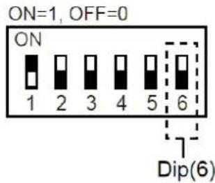
Card Identifier Setting
To set the reader to only read DES-ID (for MIFARE DESFire cards) or GID (GeoVision Identifier) formatted cards, turn ON for the DIP (6).
Note:
- GV-AS DES cards contain two types of ID: UID (Unique Identifier) and DES-ID. When only DES-ID is required, turn on the DIP (6).
-
Every time when the DIP settings are changed, the reader needs to be restarted to apply them.
-
Cable Connector: Connect the reader to the controller based on the following pin definitions:
| Pin | Wire Color | Wiegand | RS-485 |
| 1 | Red | DC 12V | DC 12V |
| 2 | Black | Ground | Ground |
| 3 | Yellow | - | RS-485+ |
| 4 | Deep Blue | - | RS-485- |
| 5 | Gray | - | - |
| 6 | Pink | - | - |
| 7 | White & Black | Ground | - |
| 8 | Orange | - | - |
| 9 | Brown | Green LED Control | - |
| 10 | Purple | Beep Control | - |
| 11 | White | Case Sensor (To Controller GND) | - |
| 12 | Green | Case Sensor (To Controller Temper Sensor) | - |
| 13 | Red & Black | Wiegand Data 0 | - |
| 14 | Light Blue | Wiegand Data 1 | - |
Note: The RS-485 interface supports either RS-485 or OSDP communication but not both at the same time.
6.4 Installation
natural_image
Pure technical diagram of a mechanical component with no text, numbers, or symbols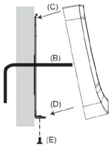
Before the hardware installation, refer to Physical Descriptions for the Node ID settings.
A. Mount the backplate onto the wall or back box (US standard 120 type). Note DO NOT overtighten the backplate screws during installation to prevent distortion.
B. Connect the wires in accordance with the Writing Note below.
C. Make sure the backplate and the upper cover guide of the reader are aligned.
D. Install the upper cover of the reader to the backplate.
E. Fasten the screw onto the bottom of the reader.
Wiring Note:
- Use minimum 22 AWG double-shielded aluminum mylar foil twisted pair cable for the connection between the reader and the controller.
- In order to reduce long distance noise, the isolated net of transmission cable should connect to both ends of device ground.
- The distance between two readers should be over 30 cm to prevent radio frequency interference from each other.
- Mounting the reader around metal could affect read range. Metal of any type around the reader should be avoided while mounting.
- The distance between the reader and the controller should not exceed 30 meters (98 ft) (for Wiegand model only).
- For optimum read range, use DC Linear power adaptor for the reader's power supply.
- In order to ensure the reader's normal operation, input voltage should be 12V±10%.
- If the reader is installed in an open area or highly humid environment, it is recommended to protect the reader with an external shielding cover.
- RS-485 communication baud rate is 9600.
6.5 Keypad
When using the reader, you can enter the door's Common Password or the card's PIN code on the keypad to gain access. The access mode is set in GV-ASManager (software).
- 0\~9 Number Keys: Press the number keys to enter a PIN code or password.
● E Key: Press the E key to confirm an entry.
● C Key: Press the C key to cancel an entry.
IMPORTANT: The Card and PIN Code mode requires users to enter the card's PIN code, press the E key to confirm the code, and then present the card to gain access.
6.6 LED Status and Beeper
The reader has the following LED status and beeper actions by default:
| Condition | Wiegand | RS-485 |
| Standby | Constant Red | No light |
| Access Denied | Beep once (No LED) | Flash Red momentarily + Beep three times |
| Access Granted | Beep once (No LED) | Flash Green momentarily + Beep twice |
The reader includes external control wires for the Green LED and Beeper for Wiegand connection. You can change the default settings of the LED and Beeper by connecting these control wires to the GV-AS Controller.
6.7 Firmware Upgrade
GeoVision periodically updates its website with the latest firmware. Using the provided tool, the new firmware can be easily installed on the reader. For how to upgrade the firmware, see 3.7 Firmware Upgrade.
6.8 Specifications
For details, please see the datasheet.
For the number of readers supported by a variety of GeoVision controllers, see the compatibility table.
Chapter 7 GV-R1354
The mini card reader GV-R1354, with only 8 cm tall, can be integrated into any standard access control systems through its Wiegand and RS-485 interfaces. Mini but complete, GV-R1354 has weather-sealed and IP56-compliant housing, perfect for both indoor and outdoor applications.
7.1 Packing List
- GV-R1354
- Data Cable
7.2 Compatible Products
GV-ASManager: V5.3.3 or later
GV-AS Controllers: GV-AS210 / 2110 / 2120, GV-AS810 / 8110 / 8111, GV-AS410 / 4110 / 4111, GV-AS1620
Note: To connect the reader to GV-AS Controllers via RS-485, it is required to use the following products and versions: GV-AS210 / 2110 / 2120 / 410 / 4110 / 4111 V2.40 (or later) and GV-AS1620 V1.04 (or later).
7.3 Physical Descriptions
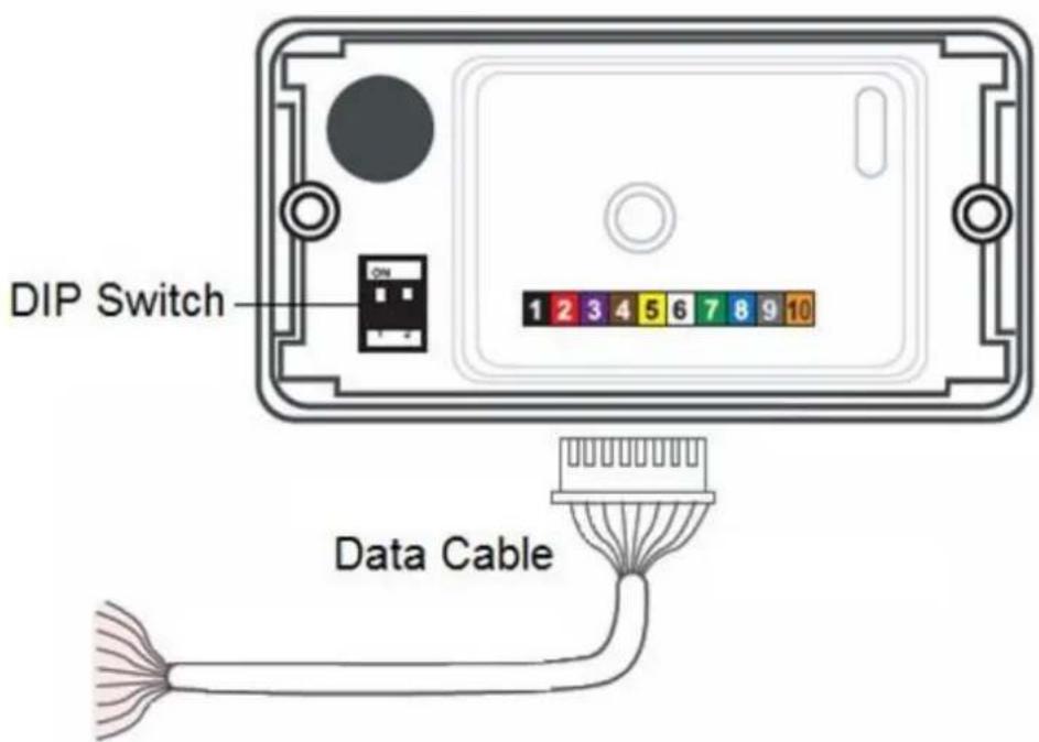
- DIP Switch: Used to set up card formats and communication signals. By default, the switch No. 1 is set to OFF for reading UID (Unique Identifier), and the switch No. 2 is set to ON for sending RS-485 and Wiegand signals simultaneously.
| No. | Position | Description |
| 1 | ON | Read GID and DES-ID |
| OFF (Default) | Read UID only | |
| 2 | ON (Default) | Send both RS-485 and Wiegand signals |
| OFF | Send RS-485 signals only | |
| Note: Every time when the setting is changed, the reader needs to be restarted to apply the change. | ||
● Data Cable: Connect the reader to GV-AS Controller based on the following pin definitions:
| No | Wire Color | Description |
| 1 | Black | DC Power 0 V (GND) |
| 2 | Red | DC Power 12V |
| 3 | Purple | Beeper Input (Low Sound) |
| 4 | Brown | Green LED |
| 5 | Yellow | Red LED |
| 6 | White | N/A |
| 7 | Green | Wiegand Data 0 |
| 8 | Blue | Wiegand Data 1 |
| 9 | Gray | RS-485 (A+) |
| 10 | Orange | RS-485 (B-) |
7.4 Installation
- Using a self-prepared flat head screwdriver, pry apart the back cover from the enclosure's edge.
- Connect the supplied Data Cable to the reader.
- Secure the reader onto the wall with 2 self-prepared screws.
7.5 ID, Beeper and LED Settings
The QR1352/ DES1352/R1354 Setup AP allows you to set the reader's ID number, beeper and LED. The program can be downloaded from our website.
A single RS-485 interface on the controller can connect up to 8 readers. In order for the controller to detect multiple connected readers, you must assign each one a unique ID number.
The reader will beep by default when a card approaches, whether granted or rejected. You can alter how the reader reacts when approached using the Setup AP, from a beep to a blinking red or green LED.
After downloading and installing the QR1352/ DES1352/R1354 Setup AP on a PC, first connect the reader to the PC using a RS-485 to USB converter, as illustrated below.
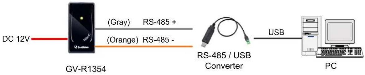
flowchart
graph LR
    A["DC 12V"] --> B["GV-R1354"]
    B --> C["(Gray) RS-485 + (Orange) RS-485 -"]
    C --> D["RS-485 / USB Converter"]
    D --> E["USB"]
    E --> F["PC"]
Note:
- The ID setting is only required for the reader to be connected to a controller through RS-485.
-
The beep and LED settings are applicable to both RS-485 and Wiegand readers.
-
Run the Setup AP.
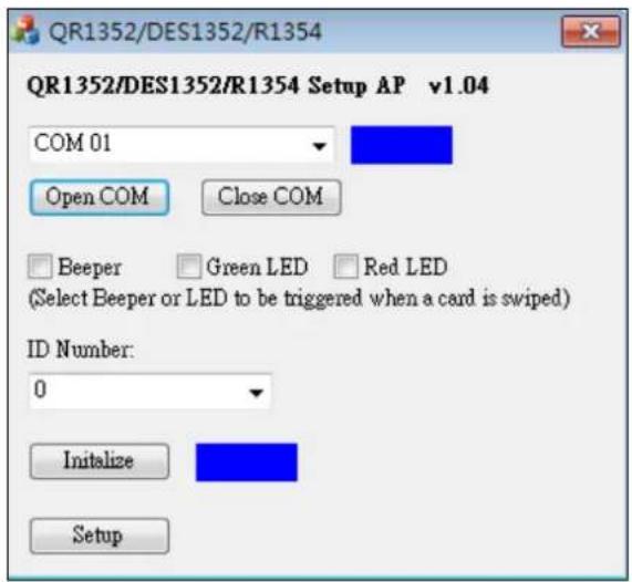
- Select the COM port that is connected to the reader and click Open COM. A blue square should appear next to the COM port box to indicate the COM port selected is correct.
- The beeper is enabled by default. To change the reader's reaction when approached, select Beeper, Green LED and/or Red LED. If you select both Beeper and Green LED, for example, when the reader is approached, it will beep together with a flashing green LED.
- Only for a RS-485 reader, select an ID number for the reader. The ID number ranges from 0 to 7.
- Click Setup. The settings are sent to the reader.
- Connect another reader to the computer, and follow the instructions above for setup.
Note:
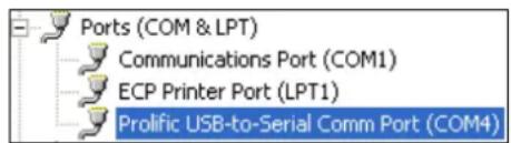
- If the COM port is incorrect, an "Error opening serial port" message will appear. To verify the COM port connected to the reader, go to Windows Device Manager. In the Ports (COM & LPT) field, you should see the entry for Prolific USB-to-Serial Comm Port and the COM number currently in use.
- The reader has the following default access reactions. If you change default beep sounds to green LED using the Setup app, it will react as below:
For RS-485 readers,
- One beep when a card approaches (default) → Flashing green LED when a card approaches
- Another one beep with green LED upon access granted
- Another two beeps with red LED upon access denied
For Wiegand readers,
- One beep upon access granted (default)→ Flashing green LED upon access granted
- One beep upon access denied (default) Flashing green LED upon access denied
7.6 Firmware Upgrade
GeoVision periodically updates its website with the latest firmware. Using the provided tool, the new firmware can be easily installed on the reader.
First of all, prepare a RS-485 / USB converter, and connect the reader to a PC as illustrated in 7.5 Configure the ID, Beeper or LED.
-
Download Firmware Upgrade Tool from our website.
-
Run the Tool. This dialog box appears.
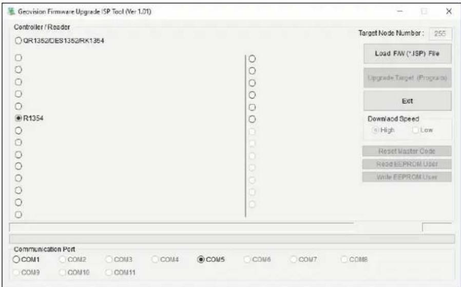
- Select Load F/W (*ISP) File to locate the firmware file.
- Select Upgrade Target (Program) to start firmware upgrade.
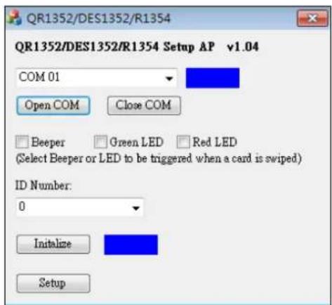
- When the firmware upgrade is complete, run the Setup App to initialize the reader.
-
Select the COM port that is connected to the reader, and select Open COM.
-
Select Initialize. When the initialization is complete, a Success message will be displayed.
7.7 Specifications
For details, please see the datasheet.
For the number of readers supported by a variety of GeoVision controllers, see the compatibility table.
Chapter 8 GV-DFK1355
GV-DFK1355 is a keypad reader capable of reading PIN codes and access cards. It features a slim profile design, making it suitable for installation on a narrow door frame or in tight spaces. Thanks to its Wiegand and RS-485 interfaces, GV-DFK1355 can be connected to a variety of access control systems. With an ingress protection rating of IP66, the reader can be used in any environment.
Additionally, the GV-DFK1355 reader, which has two inputs (Exit Button and Door Sensor) and one output (Door Lock), can control a single door when combined with the GV-AS Bridge controller and the cloud-based software GV-Cloud Access Control.
8.1 Packing List
- GV-DFK1355
- Cable
- Hex Key Wrench
- Screw x 3
- Quick Start Guide
8.2 Compatible Products
• GV-ASManager (software): V5.3.3 or later
- GV-AS210 / 2110 / 2120, GV-AS810 / 8110 / 8111, GV-AS410 / 4110 / 4111 (controller): V2.41 or later (only Weigand interface supported)
• GV-AS1620 (controller): V1.05 or later
• GV-CS1320 (controller): V3.10 or later
Cloud Integration
• GV-Cloud Access Control (cloud-based software): V1.00 or later
• GV-AS Bridge (controller): V1.00 or later
Note: To connect GV-DFK1355 to the cloud-based software GV-Cloud Access Control, GV-AS Bridge is required. See 8.8 GV-Cloud Access Control Integration.
8.3 Physical Descriptions
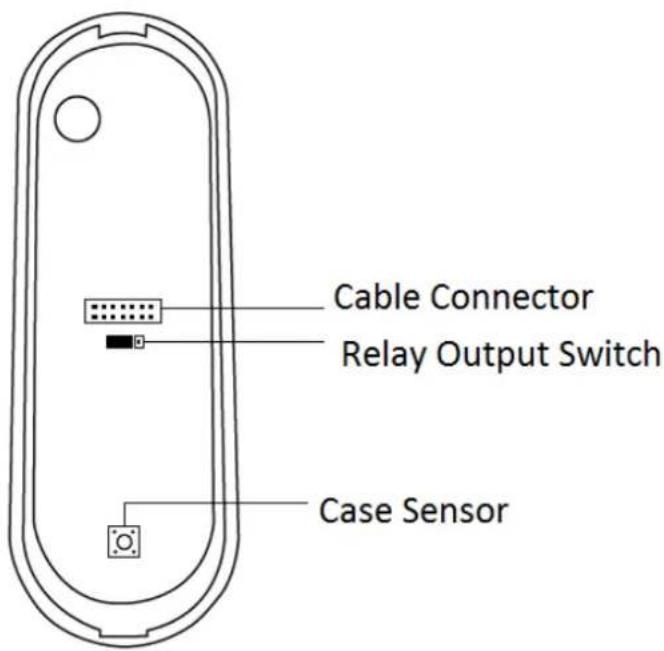
- Cable Connector: Connect the reader to the controller based on the following pin definitions:
| Pin | Wire Color | Wiegand | RS-485 |
| 1 | Red | DC 12V | DC 12V |
| 2 | Black | Ground | Ground |
| 3 | Yellow | - | RS-485+ |
| 4 | Blue | - | RS-485- |
| 5 | Gray | - | Input 2 (Exit Button; NO) |
| 6 | Pink | - | Relay + |
| 7 | Orange & White | Relay - | |
| 8 | Orange | - | Input 1 (Door Sensor; NC) |
| 9 | Brown | Green LED Control | - |
| 10 | Purple | Beep Control | - |
| 11 | White | Case Sensor GND(To Controller Input COM) | - |
| 12 | Green | Case Sensor(To Controller Temper Sensor) | - |
| 13 | Red & White | Wiegand Data 0 | - |
| 14 | Gray & White | Wiegand Data 1 | - |
- Built-in Relay
The relay is set to NO (Normal Open) by default.
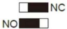
When Electric Bold Lock is used, connect wires to COM (Relay -) and NC (Relay +) contacts. When Electric Strikes is used, connect wires to COM (Relay -) and NO (Relay +) contacts.
Note:
- By default, Input 1 (Door Sensor) is set to NC (Normal Closed) and Input 2 (Exit Button) is set to NO (Normal Open), and neither of these settings cannot be changed.
- The RS-485 interface supports either RS-485 or OSDP communication but not both at the same time.
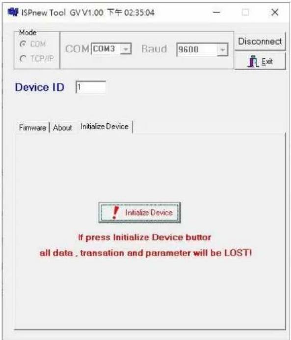
- If you want to switch from OSDP to Wiegand communication, you must first initialize the reader with the Firmware Upgrade Tool. For details on using the tool, see 3.7 Firmware Upgrade.
8.4 Installation
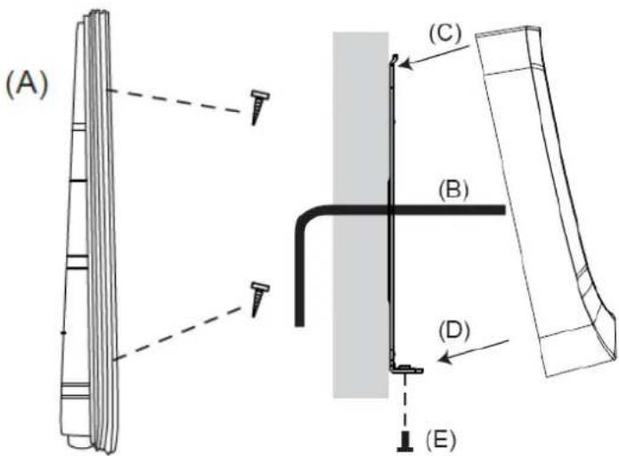
A. Mount the backplate onto the wall or back box (US standard 120 type). Note DO NOT overtighten the backplate screws during installation to prevent distortion.
B. Connect the wires in accordance with the Writing Note below.
C. Make sure the backplate and the upper cover guide of the reader are aligned.
D. Install the upper cover of the reader to the backplate.
E. Fasten the screw onto the bottom of the reader.
Wiring Note:
- Use minimum 22 AWG double-shielded aluminum mylar foil twisted pair cable for the connection between the reader and the controller.
- In order to reduce long distance noise, the isolated net of transmission cable should connect to both ends of device ground.
- The distance between two readers should be over 30 cm to prevent radio frequency interference from each other.
- Mounting the reader around metal could affect read range. Metal of any type around the reader should be avoided while mounting.
- The distance between the reader and the controller should not exceed 30 meters (98 ft) (for Wiegand model only).
- For optimum read range, use DC Linear power adaptor for the reader's power supply.
- In order to ensure the reader's normal operation, input voltage should be 12V±10%.
- If the reader is installed in an open area or highly humid environment, it is recommended to protect the reader with an external shielding cover.
- RS-485 communication baud rate is 9600.
8.5 Keypad
When using the reader, you can enter the door's Common Password or the card's PIN code on the keypad to gain access. The access mode is set in GV-ASManager (software) or GV-Cloud Access Control (cloud-based software).
- 0\~9 Number Keys: Press the number keys to enter a PIN code or password.
● # Key: Press the # key to confirm an entry.
● * Key: Press the * key to cancel an entry.
IMPORTANT: The Card and PIN Code mode requires users to enter the card's PIN code, press the # key to confirm the code, and then present the card to gain access.
8.6 LED Status and Beeper
The reader has the following LED status and beeper actions by default:
| Condition | Wiegand | RS-485 |
| Standby | Constant Red | No light |
| Access Denied | Beep once (No LED) | Flash Red momentarily + Beep three times |
| Access Granted | Beep once (No LED) | Flash Green momentarily + Beep twice |
The reader includes external control wires for the Green LED and Beeper for Wiegand connection. You can change the default settings of the LED and Beeper by connecting these control wires to the GV-AS Controller.
8.7 ID and Card Identifier Settings
The DFK1355 Setup AP allows you to set the reader's ID number and card identifier. The program can be downloaded from our website.
A single RS-485 interface on the controller can connect up to 8 readers. For the controller to detect multiple connected readers, you must assign each one a unique ID number. The GV-DFK1355 reader can be integrated with cloud-based access control management by connecting to the RS-485 interface of the GV-AS Bridge controller; see 8.8 GV-Cloud Access Control Integration.
The reader by default reads the UID (Unique Identifier) on access cards or key fobs. You can set the reader to read GID (GeoVision Identifier) or DES-ID instead.
After downloading and installing the DFK1355 Setup AP on a PC, first connect the reader to the PC using a RS-485 to USB converter, as illustrated below.

flowchart
graph LR
    A["DC 12V"] --> B["GV-DKF1355"]
    B --> C["(Yellow) RS-485 + (Blue) RS-485 -"]
    C --> D["RS-485 / USB Converter"]
    D --> E["USB"]
    E --> F["PC"]
- Run the Setup AP.
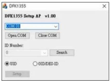
- Select the COM port that is connected to the reader and click Open COM. A blue square should appear next to the COM port box to indicate the COM port selected is correct.
- Select an ID number for the reader. The ID number ranges from 1 to 8.
- Select GID/DES-ID to set the reader to read the card identifier of GID or DES-ID.
- Click Setup.
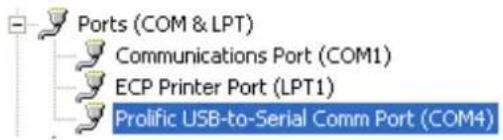
Note: If the COM is incorrect, an "Error opening serial port" message will appear. To verify the COM port that is connected to the reader, go to Windows Device Manager. In the Ports (COM & LPT) field, you should see the entry for Prolific USB-to-Serial Comm Port and the COM number currently in use.
8.8 GV-Cloud Access Control Integration
The GV-DFK1355 reader, which has two inputs (Exit Button and Door Sensor) and one output (Door Lock), can control a single door when combined with the GV-AS Bridge controller and the cloud-based software GV-Cloud Access Control.
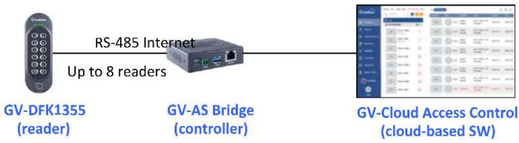
flowchart
graph LR
    A["GV-DFK1355 (reader)"] -->|RS-485 Internet Up to 8 readers| B["GV-AS Bridge (controller)"]
    B --> C["GV-Cloud Access Control (cloud-based SW)"]
The RS-485 interface on GV-AS Bridge can support up to 8 readers. When connecting multiple readers, you must assign each one a unique ID so that GV-AS Bridge can recognize them. For how to configure the reader's ID, see 8.7 ID and Card Identifier Settings.
Input 1 of the reader is for a Door Sensor with NC (Normal Closed) and Input 2 is for an Exit Button with NO (Normal Open); neither of these settings can be changed. The reader's Relay is made for a Door Lock, and you can switch between NO and NC by using the reader's switch. See 8.3 Physical Descriptions.
Note: Based on the connected output (Door Lock) on GV-DFK1355, only the door alarm statuses "Held Open", "Force Open", and "Lockdown" are available on GV-Cloud Access Control.
Force Open
- When "Force Open" is enabled on the reader, it will continue to beep, and the alarm status can only be cleared using GV-Cloud Access Control, or swipe a valid access card.
Held Open
- The "Held Open" alarm is generated when Held Open Time expires, which begins to countdown when the door lock is engaged but the door remains open.
- When the "Held Open" alarm is generated, the reader will continue to beep until the door is closed.
- The default values for Held Open Time and Lock Reset Time are 5 and 10 seconds respectively. You can alter the duration using GV-Cloud Access Control.
Lockdown
- When the door is forcibly locked down by GV-Cloud Access Control, you can open it by pressing the Exit button.
To connect to GV-AS Bridge:
- Connect the RS-485 wires of the reader to GV-AS Bridge together.
- On the GV-AS Bridge Web interface, select Extended Reader Configuration. This page appears.
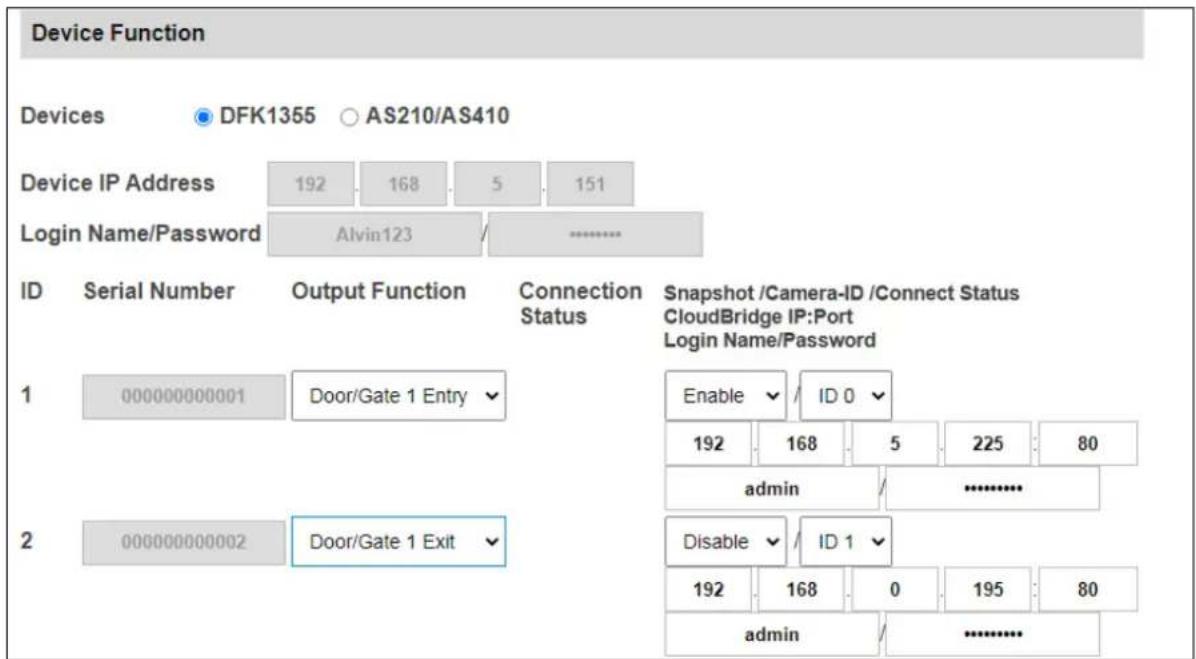
- Select DFK1355.
- Based on the Reader ID, specify each reader's output function, such as Door/Gate 1 Entry.
- Click Submit. The green Connection Status indicates the successful connection.
For details, see 1.6.3 Extended Device, GV-AS Bridge Installation Guide.
8.9 Firmware Upgrade
GeoVision periodically updates its website with the latest firmware. Using the provided tool, the new firmware can be easily installed on the reader. For how to upgrade the firmware, see 3.7 Firmware Upgrade.
8.10 Specifications
For details, please see the datasheet.
For the number of readers supported by a variety of GeoVision controllers, see the compatibility table.
Appendix
What to do if RS-485 connection fails?
When a reader successfully connects to GV-AS Controller via RS-485, the Controller's Web interface should show a green tick under Connection Status, and the reader's LED should switch off from a continuous red.
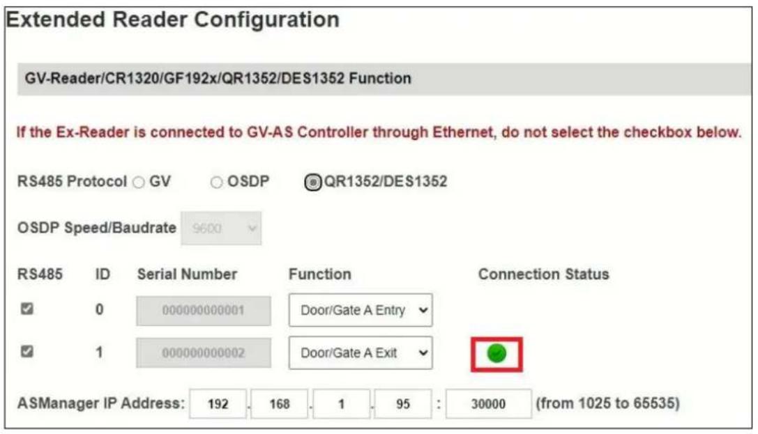
If the reader's LED remains red and there is no successful connection status on the Web interface, try adding a 180 Ohms terminal resistor on the RS-485 terminal block of the reader to extend the range of data communication.
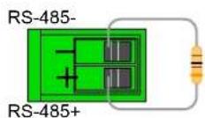
Terminal Resistor
- © 2023 GeoVision, Inc. All rights reserved.
- Notice
- Notice for GV-RKD1352
- Federal Communication Commission Interference Statement
- Preface
- Naming and Definition
- Note for Waterproofing
- Contents
- Chapter 3 GV-RKD1352....35
- Chapter 4 GV-R1355....42
- Chapter 5 GV-RKR1355....47
- Chapter 6 GV-RKV1355....53
- Chapter 7 GV-R1354....58
- Chapter 8 GV-DFK1355....64
- Appendix 73
- Chapter 1 GV-Reader1251 / 1352 V2 and GV-SR1251
- Packing List
- For GV-Reader 121 / 1352 V2
- For GV-SR1251
- Installation
- Electric Wire
- Switch Settings of GV-Reader1251 / 1352 V2
- Define the ID of GV-SR1251
- Note:
- Connect the Reader to GV-AS Controller
- Connect through Wiegand Interface
- Connect through RS-485 Interface
- Connect to GV-DVR/NVR and Third-Party Controllers
- Overlay Card Numbers on GV-DVR/NVR Live View
- Control the Beeper and LED
- Chapter 2 GV-RK1352 / R1352 / DFR1352
- Packing List
- Physical Descriptions
- Electric Wire
- Keypad (GV-RK1352 Only)
- Key: Press the # key to confirm an entry.
- LED and Beeper
- Connect the Reader to GV-AS Controller
- Connect through Wiegand Interface
- Connect through RS-485 Interface
- Define Readers on GV-AS Controller Web Interface
- Click Submit.
- Install GV-R/RK/DFR Setup AP
- Downloading from GeoVision Website
- Overlay Card Numbers on GV-DVR/NVR Live View
- Define the ID and Set the Reader to Slave
- Add the Reader to GV-DVR/NVR
- Control the Beeper and LED
- Enable External Control on the Reader
- Connect the Beeper and LED
- Wiring LED to GV-AS Controller
- Wiring Beeper to GV-AS Controller
- Set the Beeper and LED for Each Door/Gate
- Configure Card Identifier
- Run GV-R/RK/DFR Setup AP.
- Firmware Upgrade
- Important Notes before You Start
- To upgrade firmware:
- Accessory (GV-RK1352 and GV-R1352 Only)
- Connecting GV-MountA900
- Chapter 3 GV-RKD1352
- Packing List
- Compatible Products
- Physical Descriptions
- Card Identifier Setting
- Installation
- Wiring Note:
- Keypad
- LED Status and Beeper
- Firmware Upgrade
- Specifications
- Chapter 4 GV-R1355
- Packing List
- Compatible Products
- Physical Descriptions
- Installation
- LED Status and Beeper
- Firmware Upgrade
- Specifications
- Chapter 5 GV-RKR1355
- Packing List
- Compatible Products
- Physical Descriptions
- Installation
- Keypad
- LED Status and Beeper
- Firmware Upgrade
- Specifications
- Chapter 6 GV-RKV1355
- Packing List
- Compatible Products
- Physical Descriptions
- Installation
- Keypad
- LED Status and Beeper
- Firmware Upgrade
- Specifications
- Chapter 7 GV-R1354
- Packing List
- Compatible Products
- Physical Descriptions
- Installation
- ID, Beeper and LED Settings
- For RS-485 readers,
- For Wiegand readers,
- Firmware Upgrade
- Specifications
- Chapter 8 GV-DFK1355
- Packing List
- Compatible Products
- Cloud Integration
- Physical Descriptions
- - Built-in Relay
- Installation
- Keypad
- LED Status and Beeper
- ID and Card Identifier Settings
- GV-Cloud Access Control Integration
- Force Open
- Held Open
- Lockdown
- To connect to GV-AS Bridge:
- Firmware Upgrade
- Specifications
- Appendix
- What to do if RS-485 connection fails?
Brand : Geovision
Model : GV-DFK1355
Category : Security Access Control System