
PRN290DX - Refrigerator Premium Levella - Free user manual and instructions
Find the device manual for free PRN290DX Premium Levella in PDF.


| Product Type | Freestanding Refrigerator with Freezer |
| Brand | Premium Levella |
| Model | PRN290DX |
| Total Net Capacity | Approximately 290 liters (estimated from model number) |
| Refrigerator Net Capacity | Approximately 200 liters |
| Freezer Net Capacity | Approximately 90 liters |
| Overall Dimensions (H x W x D) | Approximately 170 x 60 x 65 cm |
| Weight | Approximately 65 kg |
| Power Supply | 220-240 V, 50 Hz, 1.5 A |
| Energy Consumption | Approximately 350 kWh per year |
| Energy Efficiency Class | E (estimated) |
| Climate Class | N-ST (normal to subtropical) |
| Temperature Control | Mechanical dial with separate refrigerator and freezer controls |
| Defrosting | Manual defrost for freezer, automatic defrost for refrigerator |
| Shelves | Adjustable glass shelves in refrigerator compartment |
| Crisper Drawers | Two humidity-controlled crisper drawers for fruits and vegetables |
| Freezer Compartment | Three wire shelves for storage, ice cube tray included |
| Door Storage | Multiple door bins for bottles, jars, and dairy products |
| Reversible Door | Yes, can be reversed for left or right opening |
| Lighting | Interior LED light for refrigerator compartment |
| Noise Level | Approximately 42 dB |
| Cleaning and Maintenance | Clean interior with mild detergent; defrost freezer regularly; clean condenser coils annually |
| Safety Features | Child lock on temperature control; automatic alarm if door left open |
| Spare Parts Availability | Contact authorized service center for genuine parts |
Frequently Asked Questions - PRN290DX Premium Levella
User questions about PRN290DX Premium Levella
0 question about this device. Answer the ones you know or ask your own.
Ask a new question about this device
Download the instructions for your Refrigerator in PDF format for free! Find your manual PRN290DX - Premium Levella and take your electronic device back in hand. On this page are published all the documents necessary for the use of your device. PRN290DX by Premium Levella.
USER MANUAL PRN290DX Premium Levella
READ THE "SAFETY PRECAUTIONS" IN THIS MANUAL.
CONTENTS
SAFETY PRECAUTIONS .... 1
PARTS IDENTIFICATION .... 3
USINGINTRODUCTION 5
The aim of such procedure is to describe the correct operations for safe repair and maintenance.
The operations described below must be duly followed during repair operations: the producer disclaims any responsibility in case of lack of application or partial application of the procedure described.
Please read the following instructions before servicing the unit
- Check the set for electric losses.
- Unplug prior to servicing to prevent electric shock.
- Whenever testing with power on, wear rubber gloves to prevent electric shock.
- If you use any kind of appliance, check regular current, voltage and frequency.
- Don't touch metal products in the freezer with wet hands. This may cause frostbite.
- Prevent water from falling onto electric elements.
- When standing up after having checked the lower section of the refrigerator with the upper door opened, move with care to avoid hitting the upper door.
- When tilting the unit, remove any materials inside, especially the thin plates (ex. Glass shelf or books.)
- When servicing the evaporator, wear cotton gloves to prevent injuries from the sharp evaporator fins.
- Leave the replaced components of the refrigerating cycle to a specialized service center. The refrigerant and oil inside the circuit may pollute the environment.
- When you discharge the refrigerant, wear the protective safety glasses or goggle to protect the eyes.
- When you repair the cycle system in refrigerator, the work area must be well ventilated.
DO NOT USE FLAMES OR HEAT SOURCES AND DO NOT SMOKE IN ALL THE AREA AROUND THE UNIT IF THE REFRIGERANT USED IS R600a OR R290 AND IF ANY FLAMMABLE GASES OR OXYGEN OR OIL ARE USED DURING THE MAINTENANCE SERVICE

SAFETY PRECAUTIONS AND WARNINGS FOR SERVICING UNITS USING R600a/R290:
- It is strictly prohibited to open the refrigeration system in user's home, maintenance should be carried on in opened areas and must keep good ventilation throughout to prevent R600a/R290 local gas accumulation that may cause potential safety hazard
- the refrigerant' in the cooling system must be discharged outdoor, it is strictly to produce to discharge the refrigerant in any closed area
- STATIC ELECTRICITY HAZARD: to avoid electrostatic sparks, all the equipments for gas charging must be reliable grounded
- After the gas charging is done, to seal the cooling circuit the brazing process is strictly forbidden, other methods that don't use flames or heat sources should be used
PARTS IDENTIFICATION
COOLER

1.Light box
2. Thermostat components
3. Doors
4. Decorative plate
5.Caster
6.Body
USING INTRODUCTION
COOLER
- When you install the unit in the shop, check that it is not under direct sunrays, it is in the colder area of the shop, there is free air ventilation all around the unit (otherwise the skin condensers cannot exchange heat)
- If the unit was transported laid down, wait 24hour before plug in (to allow the oil of compressor to return to compressor)
- Don't put food or drinks in the unit before the temperature inside is cold: plug in the empty unit and wait at least 1 hour that the pull down finish and the compressor starts to cycle ON and OFF, then load the unit
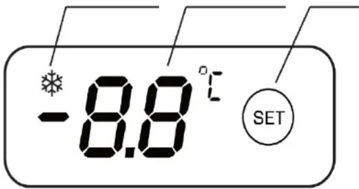
- Temperature adjustment: press the SET key to enter the setting state of the target temperature, the temperature display window displays the current setting temperature and flashes, continue to press the SET key, the temperature changes cyclically between 0\~10°C, after adjusting to the target temperature, no key operation for 5 seconds, the target temperature automatically saves, exit the setting state
The factory setting temperature is 5℃
- Defrosting: the system automatically defrosts, when the system enters the defrosting state, the refrigeration indicator (snowflake) flashes
- System switch: Long press the SET key for 8 seconds to power on/off the system. When the system is shut down, the cooling indicator is off and the temperature is displayed as "--".
Refrigeration instruction
Temperature indication Temperature setting
NOTE:
The temperature display window shows that E1 is the temperature sensor fault alarm. Please call the warranty number when this fault code occurs
COOLER
- SEASONAL USE
When the unit is kept unused for a long time, please take note of the following procedures:
- unplug the unit;
- clean and dry well the tank;
- leave the covers half open to prevent bad smells forming;
-
cover the unit with a curtain, place it in a dry room and sheltered from the atmospheric agents.
-
Handle with care, do not throw things into the compartments that may damage the tank's walls.
- DON'T PUT WARM FOOD INSIDE THE COMPARTMENTS, THE FOOD'S TEMPERATURE SHOULD BE AT AMBIENT TEMPERATURE OR BELOW. The food stored in the compartments should be packaged with non-toxic plastic bags and the drinks properly sealed to avoid excessive ice build up on the walls.
- Do not fully load the compartment all at once, gradually increase the amount of storage.
- Keep a certain distance between the storage items in the compartment, in order to facilitate the air cooling flow and uniform temperature.
- In order to reduce the energy consumption, reduce as much as possible the number of door's openings and shorten the time the door is opened.
A schematic drawing of a household refrigerator with the simplest cycle option is shown in Fig. 1.
The main components of the systems are the hermetic piston compressor (Fig.2), the condenser, the non adiabatic capillary tube with the suction line heat exchanger, the evaporator and the cabinet.
![graph TD A["condenser"] --> B["capillary tube with suction line heat exchanger"] B --> C["evaporator"] C --> D["cabinet"] D --> E["Molecular dryer"] F["compressor"] --> G["QComp"] G --> H["Pel"] H --> I["Qc"] I --> B J["Qcab"] --> C K["QCab"] --> D style A fill:#f9f,stroke:#333 style B fill:#ccf,str…](/content/2026/05/1044192/images/c938ab52ab504a35925a0d2b914ea2ef122d599e6c62855a1077e9351a24f579.jpg)
Figure 1: Schematic drawing of a household refrigerator with one temperature zone
The compressor draws in the refrigerant fluid from the evaporator by reducing the pressure in this component. The fluid is compressed by the compressor and moves to the condenser. In the condenser the refrigerant fluid under high pressure releases heat to the environment and becomes liquid. The next component of the circuit is the control device, which may be a capillary tube or an expansion valve. The control element reduces the pressure of the liquid refrigerant which was formed in the condenser. This drop in pressure permits the refrigerant to evaporate at low temperatures and return to the gaseous state when passing through the evaporator.
The change from a liquid to gaseous state requires heat. So the refrigerant fluid removes the heat from inside the refrigeration system through the evaporator. The condenser releases this heat into the environment. The control element offers a certain resistance against the refrigerant's circulation, separating the high pressure (condenser) from the low pressure (evaporator) side.
The refrigeration system also uses a filter drier with desiccant to retain any water that may be left in the system.
The oil cooling tube that exists in some compressors is used to help reduce the compressor temperature.
Lastly, there are systems that use a suction accumulator to evaporate any residual liquid refrigerant, stopping it from returning through the suction line.

Figure 2: Hermetic piston compressor for household refrigerators with opened shell

Fig. 7-10 Cutaway view of a compressor. Note the motor is on the bottom of the compressor and the piston is on the top. (Tecumseh)
DISASSEMBLY
Remove light box
- Use a Phillips screwdriver to remove four screws counterclockwise.


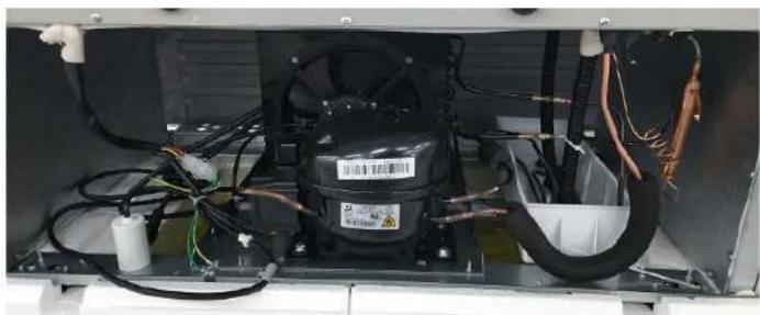
Remove compressor compartment grid
- Use a Phillips screwdriver to remove screws counterclockwise.

WIRING DIAGRAM
This circuit diagram is for reference only. Please refer to the product nameplate for details
![graph TD A["cable"] --> B["L"] A --> C["PEN"] A --> D["interruptor interior lampapa"] A --> E["interruptor exterior lampapa"] A --> F["evaporación ventilador"] A --> G["evaporación ventilador"] A --> H["sensor de temperatura"] A --> I["control electrónico de temperatura"] A --> J["calefacción"] A --…](/content/2026/05/1044192/images/1dba89c41b59d9da7974c1ad9f6153a2e942f443eb13d9ce420a131c21a9cb21.jpg)
COMPRESSOR
1) Role
The compressor intakes low temperature and low pressure gas evaporated from Evaporator of the Refrigerator, and condenses this gas to high Temperature and high pressure gas, and then plays delivering role to Condenser.
2) Composition
The Compressor is composed of Compressor Apparatus compressing gas, Compressor Motor moving Compressor Apparatus and Case protecting Compressor Apparatus and Motor. There are PTC-Starter, and Over Load Protector (OLP) in the Compressor outside. On the other hand, because the Compressor consists of 1/1000mm processing precision components and is sealed after production in absence of dust or humidity, deal and repair with care.
3) Note for Usage
(1) Be careful not to allow over-voltage and over current.
(2) No Strike
If applying forcible power or strike (dropping or careless dealing), poor operation and noise may occur
(3) Use proper electric components appropriate to the Compressor.
(4) Note to Keep Compressor.
If Compressor gets wet in the rain and rust in the pin of Hermetic Terminal, the result may be poor operation and poor contact may cause.
(5) Be careful that dust, humidity, and flux welding don't inflow in the Compressor inside in replacing the Compressor. Dust, humidity, and flux due to welding which inflows to Cylinder may cause lockage and Noise.
PTC-STARTER
1) Composition of PTC-Starter
(1) PTC (Positive Temperature Coefficient) is a no-contact semiconductor starting device which uses ceramic material and this material consists of BaTiO3.
(2) The higher the temperature is, the higher becomes the resistance value. These features are used as starting device for the Motor.
2) Role of PTC-Starter
(1) PTC is attached to Hermetic Compressor used for Refrigerator, Show Case and starts Motor.
(2) Compressor for household refrigerator applies to single-phase induction Motor.
For normal operation of the single-phase induction motor, in the starting operation flows in both main coil and sub-coil. After the starting is over, the current in subcoil is cut off. The proper features of PTC play all the above roles. So, PTC is used as a motor starting device.
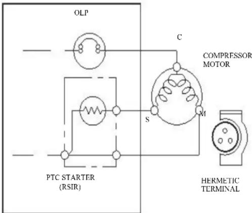
3) PTC-Applied Circuit Diagram
According to Starting Method for the Motor.
4) Motor Restarting and PTC Cooling
(1) For restarting after power off during normal Compressor Motor operation, plug the power cord after 5 min. for pressure balance of Refrigerating Cycle and PTC cooling.
(2) During normal operation of the Compressor Motor, PTC elements generate heat continuously. Therefore, if PTC isn't cooled for a while after the power has been shut off, Motor can't operate again.
5) Relation of PTC-Starter and OLP
(1) If the power is off during operation of Compressor and the power is on before the PTC is cooled, (instant shut-off within 2 min. or reconnect a power plug due to misconnecting), the PTC isn't cooled and a resistance value grows. As a result, current can't flow to the sub-coil and the Motor can't operate and the OLP operates by flowing over current in only in the main-coil.
(2) While the OLP repeats on and off operation about 3-5 times, PTC is cooled and Compressor Motor performs normal operation.
If OLP doesn't operate when PTC is not cooled, Compressor Motor is worn away and causes circuitshort and fire. Therefore, use a properly fixed OLP without fail.
6) Note to Use PTC-Starter
(1) Be careful not to allow over-voltage and over-current.
(2) No Strike
Don't apply a forcible power or strike.
(3) Keep apart from any liquid.
If liquid such as oil or water away enter the PTC, PTC materials it may break due to insulation breakdown of the material itself.
(4) Don't change PTC at your convenience.
Don't disassemble PTC and mold. If the exterior to the PTC-starter is damaged, resistance value is altered and it may cause poor starting of the compressor motor may cause.
(5) Use a properly fixed PTC.
OLP-OVERLOAD PROTECTOR
1) Definition of OLP
(1) OLP (OVER LOAD PROTECTOR) is attached to the Hermetic Compressor and protects the Motor by cutting off current in Compressor Motor in case of over-rising temperature by Binetal in the OLP.
(2) When over-voltage flows to Compressor motor, the Bimetal works by heating the heater inside the OLP, and the OLP protects Motor by cutting off current which flows to the Compressor Motor.
2) Role of the OLP
(1) The OLP is attached to the Hermetic Compressor used for the Refrigerator and Show Case and prevents the Motor Coil from being started in the Compressor.
(2) Do not turn the Adjust Screw of the OLP in any way for normal operation of the OLP. (Composition and connection Diagram of OLP).

1. COMPRESSOR AND ELECTRIC COMPONENTS
![graph TD A["Power Source."] --> B["Remove the Relay Assy from the Compressor and measure the voltage between Terminal C of Compressor and Terminals M or S of Relay Assy"] B --> C["(Rating Voltage ±10%)"] C -->|YES| D["2"] C -->|NO| E["5"] E --> F["Applied voltage isn't in the range of Rating Voltage…](/content/2026/05/1044192/images/70e4f725c53be5f5dc65af4413aff1da981db71a47b42e3dfacdcb3489562a47.jpg)
TROUBLE SHOOTING
2. RELAY ASSY (PTC AND OLP)
![graph TD A["Normal operation of Compressor is impossible or poor."] --> B["Separate the Relay Assy from Compressor and measure the resistance between M and S with a Tester or Whistone Bridge. (Figure 21)"] B --> C["Observation value is 220V/50Hz : 22Ω 30% 115V/60Hz : 6.8Ω"] [Check another electric c…](/content/2026/05/1044192/images/ec87dec27880a4f17b365dd4d7b75d40835ab9dc815e2b31d0d1068b05e646df.jpg)

Figure 21
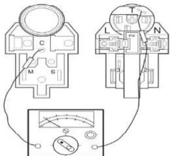
Figure 22
3. ANOTHER ELECTRIC COMPONENTS
▼ Cooling is impossible
![graph TD A["Compressor doesn't run."] --> B["Check if current flows to the following components."] C["Cause"] --> D["a. Thermistor"] --> E["Poor contacting."] C --> F["b. Starting devices"] --> G["Shorted or broken."] C --> H["c. OLP"] --> I["Poor contacting or shorted."] C --> J["d. Compressor coil…](/content/2026/05/1044192/images/55050c74fcb413a3cd2de20b1270a56c41d6781e4d654f8c17085f7e5fca9763.jpg)
4. SERVICE DIAGNOSIS CHART
| FAILURE MODE POSSIBLE CAUSES MEASURES | ||
| Not Cooling at all | Is the power cord unplugged from the outlet?Check if the power switch is set to OFF.Check if the fuse of power switch is shorted.Measure the voltage of power outlet. | Plug to the outlet.Set the switch to ON.Replace a regular fuse.If voltage is low, wire newly. |
| Cooling capacity is insufficient | Check if the unit is placed close to wall.Check if the unit is placed dose to stove, gas cooker and direct rays.Is the ambient temperature high or the room door closed?Check if put in is hotDid you open the door of the unit too often or check if the door is closed up?Check if the thermostat is set to "cold-position". | Place the unit about 10cm from the wall.Place the unit apart from these heat appliances.Cool the room temperature.Put in foods after cooled down.Don't open the door too often and close it firmly.Set the thermostat to "mid-position". |
| Foods in the Refrigerator are frozen | Is foods placed in cooling air outlet?Check if the thermostat is set to "cold-position".Is the ambient temperature below 5°C? | Place foods in higher temp. section. (Front Part)Set the thermostat to "mid-position".Set the thermostat to "warm-position". |
| Dew or ice forms in the compartment of the unit | Is liquid food stored?Check if put in food is hot.The door of the unit is opened often or the door is not closed. | Seal up liquid foods with wrap.Put in foods after cooled down.Don't open the door too often and close it firmly. |
| Dew forms in the Exterior Case | Check if ambient temperature and humidity of surroumcling air are high.Is there gap in the door packing? | Wipe dew with a dry cloth. This occurrence is solved naturally in low temperature and humidity.Fill up the gap. |
4. SERVICE DIAGNOSIS CHART
| FAILURE MODE | POSSIBLE CAUSES MEASURES | |
| Abnormal noise | Is the unit positioned in a firm and even place?Are any unnecessary objects set in the back side of the unit?Check if the Drip Tray is not firmly fixed.Check if the cover of mechanical room in below and front side is taken out. | Adjust the Adjustable feet and position in a firm place.Remove the objects.Fix it firmly on the original position.Place the cover at the original position. |
| To close the door is not handy. | Check if the door packing is dirty with filth such as juice.Is the unit positioned in a firm and even place?Is too much food putted in the unit? | Clean the door packing.Position the unit in a firm place and adjust the Adjustable feetKeep foods not too closed to the door. |
| Ice and foods smell bad | Check if the compartment is dirty.Did you keep smelly foods without wrapping?It smells of plastic. | Clean the inside surfaces of the compartment.Wrap smelly foods.The new products smell of plastic, but it disappears after 1-2 weeks. |
In addition to the items described above, refer to the followings to solve the complaint if the above measures don't solve the problem.
![graph LR A["Check if dew forms in the Freezer."] --> B["Defrosting is poor."] B --> C["Replace the Components of the defrosting circuit."] D["Check the cooling circuit."] --> E["The cooling circuit is faulty."] E --> F["Repair the cooling circuit."]](/content/2026/05/1044192/images/54879906f1cf8dfdc4ad10ef460ba000f7af45d030f370e0440be204a9793e45.jpg)
TROUBLESHOOTING CHART
| CAUSE FAILURE | RE MODE | STATE OFTHE EVAPORATOR | TEMPERATUREOF COMPRESSOR SHELL | REMARKS | |
| GAS LEAKAGE | PARTIALLEAKAGE | Freezer/Refrigeratorcompartments don't coolnormally | Low flowing sound of Refrigerantis heard and frost forms in inletonly. | A little higher thanambient temperature. | • Small discharge of refrigerant fromcompressor delivery• Normal cooling is possible if refillregular amount of refrigerant |
| FULLLEAKAGE | Freezer/Refrigeratorcompartments don't coolnormally | Flowing sound of Refrigerant isnot heard and frost isn't build up. | Equal to ambienttemperature. | • Absence of discharge of Refrigerantfrom compressor delivery• Normal cooling is possible if refillregular amount of refrigerant. | |
| CLOGGED CIRCUIT | PARTIALCLOG BYRESIDUALS | Freezer/Refrigeratorcompartments don't coolnormally | Flowing sound of Refrigerant isnot heard and frost forms in inletonly. | A little higher thanambient temperature. | • Normal discharging of refrigerantfrom compressor delivery• The capillary tube is faulty. |
| FULLCLOG BYRESIDUALS | Freezer/Refrigeratorcompartments don't cool | Flowing sound of Refrigerant isnot heard and frost isn't build up. | Equal to ambientTemperature. | • Normal discharging of Refrigerantfrom compressor delivery | |
| MOISTURECLOG | Cooling operationstops periodically | Flowing sound of Refrigerant isnot heard and frost melts. | Low than ambienttemperature | • Cooling operation restartswhen heating the inlet ofcapillary tube. | |
| DEFECTIVECOMPRESSION | COMP-RESSION | Freezer andRefrigeratorcompartments don't cool. | Low flowing sound of RefrigerantIs heard and frost forms in inletonly. | A little high than ambienttemperature | • The pressure in the high pressureside of the cooling circuit is low. |
| NO COMP-RESSION | Freezer andRefrigeratorcompartments don't cool. | Flowing sound of Refrigerant isnot heard and frost isn't cool-up. | Equal to ambienttemperature. | • There isn't pressure in the highpressure side of the cooling circuit | |
LEAKAGE DETECTION WORK FLOW
![graph TD A["Does compressor runs or not?"] -->|YES| B["Does frost build up in the Evaporator?"] B -->|Frost Build up in inlet only| C["Can you figure out if there is a gas leakage?"] C -->|YES| D["Gas leakage. (Check the leakage point)"] C -->|NO| E["Check the flow rate/discharge of refrigerant air…](/content/2026/05/1044192/images/a0e1dfc24d3eae15d818892cca519ff485a731cce639b9e804a7cff452460546.jpg)
| NO | ITEMS | CONTENTS AND SPECIFICATIONS | REMARKS |
| 1 | WELDING ROD | (1) H 30Chemical compositionAg: 30%, Cu: 27%, Zn: 23%, Cd: 20%Brazing Temperature: 710~840°C(2) Bcup-2Chemical compositionCu: About 93%P: 6.8~7.5%The rest: within 0.2%Brazing Temperature: 735~840°C | • Copper copper brazing needs copper brazing rod, copper-steel brazing needs silver brazing rod, Aluminum-copper brazing needs aluminum brazing rod• Recommend H34 containing 34% Ag in the Service Center. |
| 2 | F L U X | Brazing flux powder (Borax)It is a chemical cleaning agent that prevents oxides from forming on the surface of the molten metal | • Bcup-2needs the use of flux to increase the fluidity• Aluminum brazing: water-soluble brazing flux for aluminum applications is required |
| 3 | L O K R | (1) Both of the tubes are inserted up to the stop.(2) Both of the LOKRING are pushed up to the stop.(3) The bending point is not too close to the joint ending.(4) During the assembly it is important that both ends remain completely within the joint. | • For a hermetically sealed metal/metal connection, the tube ends have to be clean.• LOKPREP is distributed all of out-surface of the tube ends. |
| 4 | D R I E | 1) Assemble the drier within 30min. after unpacking.(2) Keep the unpacked drier at the temperature of 80~100°C. | • Don't keep the drier outdoor because humidity damages it. |
| NO | ITEMS | CONTENTS AND SPECIFICATIONS | REMARKS |
| 5 | VACCUM | (1) When measuring with pirant Vacuum (1) gauge the charging M/C, vacuum (1) degree is within 130 Pa.(2) If the vacuum degree of the circuit inside is 1300 Pa. below for low pressure and 2600 Pa for high pressure, it says no vacuum leakage state.(3) Vacuum degree of vacuum pump must be 7 Pa below after 5 min.(4) Vacuum degree must be same to the value described item (2) above for more than 20 min. | · Apply M/C Vacuum Gauge without fail.· Perform vacuum operation until a proper vacuum degree is built up.· If a proper vacuum degree isn't built up, check the leakage from the Cycle Pipe line part and Quick Coupler Connecting part. |
| 6 | DRY AND AIR NITROGEN GAS | (1) The pressure of dry air must be 12~16 bar(2) Keep the pressure at 12~16 bar also when substituting dry air for Nitrogen Gas. | |
| 7 | NIPPLE AND COUPLER | (1) Check if gas leaks with soapy water.(2) Replace Quick Coupler in case of leakage. | · Check if gas leaks from joint of the Coupler. |
| 8 | PIPE | · Put all Joint Pipes in a clean box and cover tightly with the lid so that dust or humidity don't enter. |
MAIN EQUIPMENT AND MATERIAL
| No.Equipment or MaterialFigure | No.Equipment or MaterialFigure | |||||
| 1 | Pincer |  | 7 | Potable Gas Charge Machine |  | |
| 2 | weidang Iorcn |  | 8 | Electronic Scale |  | |
| 3 | Welding Material: Wire Solder( Ag, Cu, Al) Flux |  | 9 | Leak detector: R134a 3.4g/Year R600a 2.0g/Year |  | |
| 4 | Material: R134a, R600a, N2, O2, C2H2 |  | 10 | LOKRING |  | |
| 5 | Pressure Gauge |  | 11 | LOKRING GLUE |  | |
| 6 | Vacuum Pump | 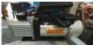 | 12 | LOKRING PLIER | [6ZZY] | |
- Before undertaking any repair operation, it is necessary to perform the following preliminary operations:
- Disconnect power cord from the wall socket; Check electric safety of product.
- Using a leak detector suitable for hydrocarbons (HC) check for leaks in the motor compartment area. Avoiding R600a /R290 leaks to form safety accident.
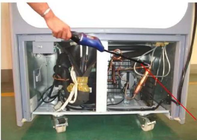
Leak detector
CAUTION: Do not bring free flames and don't smoke near the motor compartment, before the refrigeration circuit is properly emptied of R600a/R290.
Before undertaking any operations concerning the refrigerating equipment, it is ABSOLUTELY NECESSARY to empty the refrigeration circuit following the instructions given in the following paragraph. The producer disclaims any responsibility in case of lack of application or partial application of such instructions.
1. Opening of refrigeration circuit
| 1 | Move the product outside (or at least to a well aired area), in order to avoid stagnations in closed areas of the gas leaking when the circuit is opened | |
| 2 | 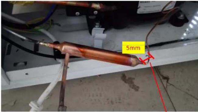 Terminal to be cut Terminal to be cut | - Cut the capillary tube 5 mm from the dryer- Plug in the unit, the compressor runs and the refrigerant flows out.Leave the compressor running for 5 minutes, then unplug the unit, gently shake the compressor, allowing a small quantity of refrigerant which is dissolved in oil to be released from the frozen oil. After 3 minutes, once again, plug in the unit and leave the compressor running for 5 minutes, when the refrigerant emission is completed, unplug the unit. |
Although the process described before is done, it is still possible to have refrigerant inside the circuit if the dryer is clogged. Cut the pipe from condenser 5mm from the dryer using only orbital tube cutters, the refrigerant outgoing and till emission is completed. This process must last 15 minutes.
Caution: It is forbidden to take off the pipe by welding method. Otherwise an explosion occurs due to flammable refrigerant (R600a/R290) inside the circuit.
4

Cut the compressor service pipe using only orbital tube cutters.
Plug in the unit and leave the compressor running.
Check that there is suction from the service pipe and blow from the condenser pipe (if there aren't, the compressor is faulty).
Wait around 15 minutes until the inner pressure is equal to the atmospheric pressure and the refrigerant emission is completed.
2. Repair or 'reirfgeration circuit
After ensuring the refrigerant has been removed completely from the refrigeration circuit, the repair can be carried out in the same way used for a standard circuit.
Caution: during welding operations, take care not to damage the electrical wiring: possible short circuit with ensuing electrical discharges may cause fire.
Sealing operations by means of brazing are allowed only if no R600a/R290 is inside the circuit.
Once the circuit is charged with propane the sealing of the process tubes must be performed WITHOUT WELDING TORCHES
5

Braze one-way valve to joint charging tube, connect the joint of the flexible gas hose of the Nitrogen tank to the one-way valve and insufflate pressurized N2 gas at 15 bars for 10-15 seconds and check that gas is coming out from capillary tube (low pressure side) and condenser pipe (high pressure side) normally.
Stop to insufflate N2 gas, wait that the gas emission is completed, then seal the capillary tube and the condenser pipe.
Insufflate N2 gas again until pressure reaches 12 bar and check the leakage point in the circuit by using an electronic leak detector.
After found out the leakage point, cut the capillary tube and the condenser pipe and wait until N2 gas emission is completed.
Make a new brazing in the leaking joint.
Insufflate N2 gas from the compressor charging tube to clean the circuit inside, the gas will come out from capillary tube and condenser pipe. This process must last 15 seconds.
Exchange dryer : R134a Dryer(XH-7), R600a Dryer(XH-9)
3. Air removal from the circuit (vacuum process) and refrigerant charge
The degree of vacuum to be performed in refrigeration circuit which use R600a/R290 is the same used for traditional circuit using HFC (R134a, R404A, etc).
At the end of the vacuum operation the value to be reached for vacuum is 14Pa (0,14mbar = 100mmHg) : this value is normally reached after 20 minutes from connection of the vacuum pump to the circuit.
Always use charge devices suitable for hydrocarbons (HC) refrigerant.
The refrigeration circuit provided with the equipment must be charged with 99.5% pure gas (R600a/R290).
The amount of refrigerant to be used is shown on the technical data plate; during charge operation the weight of the refrigerant must be accurately controlled: for optimum operation of the unit the quantity of refrigerant charged must be within a tolerance of ± 5% .
Actual charge = nominal charge ± 5%
Note: please check the dryer dimensions, as dryers with bigger volumes require additional refrigerant.
4. Sealing
Use electronic leak detector to check for possible leaks from the one way valve

EXPLODED VIEW PRN165DX PRN185DX PRN210DX PRN290DX

| MD. | DESCRIPTION | MD. | DESCRIPTION |
| 1 | CABINET | 36 | UNIVERSAL WHEEL |
| 2 | FRONT PANEL ASSEMBLY | 37 | HOLDER |
| 3 | TRANSFORMER | 38 | SUPPORT PLATE |
| 4 | / | 39 | PANEL |
| 5 | EVAPORATOR | 40 | PANEL |
| 6 | EVAPORATOR FAN | 41 | WATER DRYERBOX |
| 7 | FAN OOVER | 42 | SUPPORT PLATE |
| 8 | EVAPORATOR FAN OOVER | 43 | OOMPRES8OR |
| 9 | LIGHT BOX | 44 | WATER DRYER |
| 10 | TOP LED LIGHT | 45 | OOMPRES8OR OOVER |
| 11 | LAMP SWITCH | 46 | POW CODE |
| 12 | MAIN BOARD | 47 | LEFT HINGE |
| 13 | ELECTRICAL BOX | 48 | SUPPORTER |
| 14 | BEAM OOVER | 49 | THERMOSTAT CONNECTOR |
| 15 | INSIDE LED LIGHT | 50 | INNER WIRE |
| 16 | LEFT DOOR GASKET | 51 | BRACKET |
| 17 | LEFT DOOR | 52 | RACK |
| 18 | LEFT DOOR DANDLE | 53 | UPPER HINGE |
| 19 | RIGHT DOOR GASKET | 54 | SCREW |
| 20 | RIGHT DOOR | 55 | SEN8OR |
| 21 | RIGHT DOOR DANDLE | ||
| 22 | LEFT DOCK PLATES | ||
| 23 | RIGHT DOCK PLATES | ||
| 24 | / | ||
| 25 | WIRE | ||
| 26 | DEODRATION PANEL OOVER | ||
| 27 | DEODRATION PANEL | ||
| 28 | BEAM | ||
| 29 | BEAM BOTTOM | ||
| 30 | RIGHT HINGE | ||
| 31 | OONDEN8OR | ||
| 32 | OONDEN8OR FAN | ||
| 33 | CAPACITOR | ||
| 34 | OOMPRES8OR PANEL | ||
| 35 | SUPPORTER PANEL |


- CONTENTS
- THE AIM OF SUCH PROCEDURE IS TO DESCRIBE THE CORRECT OPERATIONS FOR SAFE REPAIR AND MAINTENANCE
- PLEASE READ THE FOLLOWING INSTRUCTIONS BEFORE SERVICING THE UNIT
- SAFETY PRECAUTIONS AND WARNINGS FOR SERVICING UNITS USING R600A/R290
- PARTS IDENTIFICATION
- USING INTRODUCTION
- COOLER
- SEASONAL USE
- DISASSEMBLY
- REMOVE LIGHT BOX
- REMOVE COMPRESSOR COMPARTMENT GRID
- WIRING DIAGRAM
- COMPRESSOR
- ROLE
- COMPOSITION
- NOTE FOR USAGE
- PTC-STARTER
- COMPOSITION OF PTC-STARTER
- ROLE OF PTC-STARTER
- PTC-APPLIED CIRCUIT DIAGRAM
- MOTOR RESTARTING AND PTC COOLING
- RELATION OF PTC-STARTER AND OLP
- NOTE TO USE PTC-STARTER
- OLP-OVERLOAD PROTECTOR
- DEFINITION OF OLP
- ROLE OF THE OLP
- COMPRESSOR AND ELECTRIC COMPONENTS
- TROUBLE SHOOTING
- RELAY ASSY (PTC AND OLP)
- ANOTHER ELECTRIC COMPONENTS
- SERVICE DIAGNOSIS CHART
- LEAKAGE DETECTION WORK FLOW
- OPENING OF REFRIGERATION CIRCUIT
- REPAIR OR 'REIRFGERATION CIRCUIT
- AIR REMOVAL FROM THE CIRCUIT (VACUUM PROCESS) AND REFRIGERANT CHARGE
- SEALING
- EXPLODED VIEW PRN165DX PRN185DX PRN210DX PRN290DX
Brand : Premium Levella
Model : PRN290DX
Category : Refrigerator