
65WR6CE - Whiteboard HISENSE - Free user manual and instructions
Find the device manual for free 65WR6CE HISENSE in PDF.


| Product Type | Interactive Whiteboard |
| Brand | Hisense |
| Model | 65WR6CE |
| Screen Size | 65 inches (165 cm) |
| Display Resolution | 3840 x 2160 (4K UHD) |
| Touch Technology | Infrared or capacitive (multi-touch, up to 20 points) |
| Brightness | 350 cd/m² |
| Contrast Ratio | 4000:1 |
| Dimensions (with stand) | Approx. 1500 x 900 x 80 mm |
| Weight | Approx. 35 kg |
| Power Supply | AC 100-240V, 50/60Hz; max. 250W |
| Connectors | HDMI (2), USB (2), VGA, Audio In/Out, RS232, LAN |
| Operating System | Embedded Android (usually 8.0 or higher) |
| Main Functions | Interactive whiteboard, annotation, screen sharing, wireless projection, built-in apps |
| Cleaning and Maintenance | Use a soft, dry cloth; avoid abrasive cleaners and liquids near openings |
| Safety Precautions | Secure to wall/stand, ensure proper ventilation, do not block vents |
| Spare Parts and Repairability | Contact Hisense support or authorized service centers; limited user-serviceable parts |
| General Information | Designed for education and business collaboration; includes remote management |
Frequently Asked Questions - 65WR6CE HISENSE
User questions about 65WR6CE HISENSE
0 question about this device. Answer the ones you know or ask your own.
Ask a new question about this device
Download the instructions for your Whiteboard in PDF format for free! Find your manual 65WR6CE - HISENSE and take your electronic device back in hand. On this page are published all the documents necessary for the use of your device. 65WR6CE by HISENSE.
USER MANUAL 65WR6CE HISENSE
Read the manual carefully and ensure you have fully understood its contents before operating this device for the first time.
Contents
- Safety Precautions....1
- Introduction ...... 8
2.1 Package Contents......8
2.2 Products View....9
2.3 Remote Control....11
- Installation Guide....13
3.1 Precautions for Installation....13
3.2 Wall Mount Kit Specifications (VESA) 14
3.3 Installing the OPS (Optional)....15
- Making Connections ......17
- Getting Started....22
5.1 Power On/Off....22
5.2 Using Gestures....23
- Serial Protocol....24
- Appendix ......27
7.1 Specification....27
7.2 Other Infomation....30
7.3 Certification and Compliance....32
7.4 EU Declaration of conformity (DOC) 33
- Troubleshooting ....39
1. Safety Precautions
Declaration
Any content and service accessed through this device, while only intended for individual non-commercial use, shall be the property of the applicable third party and subject to protection by regulations and laws on copyright, patent, trademark and other intellectual property rights. No part of such content and service may be modified, duplicated, published, uploaded, distributed, translated, marketed, or used to make and distribute products derived from it without the prior permission of the content owner or service provider.
You acknowledge and agree explicitly that you will solely bear the risk associated with the use of this device, and further you will solely bear any risk related to satisfactory quality, performance and accuracy for any content and service accessed through this device. To the maximum extent permitted by applicable law, this device and any third party's content and service is provided as it is without any guarantee, express or implied.
Manufacturer hereby declare explicitly that Manufacturer shall not be held liable for any guarantee and conditions, express or implied, related to this device and any content and service, including but not limited to warranty on marketability, satisfactory quality, fitness for a particular purpose, accuracy, quiet use and non-violation of any third party's rights; to the maximum extent permitted by applicable law, Manufacturer gives no guarantee on the accuracy, validity, timeliness, legitimacy and completeness of any content or service provided through this device, or the fitness of such device, content or service for your particular requirement, or the protection from interruption and error during operation of such device, content or service; to the maximum extent permitted by applicable law, in any case, including fault or neglect, Manufacturer shall not be held liable for legal actions or indemnity obligation arising from any consequence as a result of or related to any information loaded in this device or use of such device, content or service by you or any third party.
Any content and service provided as it is together with this device shall be the property of the applicable third party, therefore Manufacturer gives no declaration or warranty on modification, suspension, cancellation, termination or abortion thereof, and shall not be held liable for legal actions or indemnity obligation arising thereof.
Manufacturer reserves the rights to restrict the use or access of certain content or service. As the content and service are transmitted through third party's network and transmission facilities, Manufacturer undertakes no customer service thereof or the obligation for such customer service.
[Statement]
- The pictures and instructions in this user manual are for reference only, and may be different from the actual product. Please subject to the actual product. (This statement is throughout this User Manual)
• Quality upgrades, product design and specifications are subject to change without notice. - The software content service applicable to this product depends on the third party provider, and some software may not be used due to network, region, service cycle and other problems, which has nothing to do with the product quality. Please contact the third party provider for relevant details.
![HISENSE 65WR6CE - [Statement] - 1](/content/2026/05/1044184/images/dce7955ed4d36bf008e55098c62c944265148c0b9ac314d59768911fb87cef1c.jpg)
This symbol alerts user about the presence of a dangerous voltage not isolated inside the product which can be sufficiently powerful to constitute a risk of electrocution.
![HISENSE 65WR6CE - [Statement] - 2](/content/2026/05/1044184/images/a6fb22382dc608a0c1b68a3a5bc656e8c5bd3817a50f4db20827e2cb98675a05.jpg)
This symbol alerts user about the presence of important operating instructions and maintenance in the document enclosed in the package.
![HISENSE 65WR6CE - [Statement] - 3](/content/2026/05/1044184/images/4e2e9781d49509ef73d5adb5f8fd96a8a0cc9bc71066bee13dbabbc47a35e2ac.jpg)
ATTENTION
RISK OF SHOCK ELECTRIC

Do not open the back cover.
In no case the user is allowed to operate inside the device.
Only a qualified technician is entitled to operate.

AC voltage: This symbol indicates that the rated voltage marked with the symbol is AC voltage.

DC voltage: This symbol indicates that the rated voltage marked with the symbol is DC voltage.

Class I product: This symbol indicates that it requires a safety connection of protective earthing (ground).
Disposal of Used Electrical & Electronic Equipment
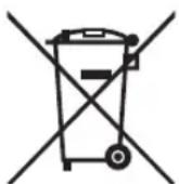

Packaging and electrical goods should be recycled appropriately, and not treated as household waste. Please dispose of this equipment at your applicable collection point for the recycling of electrical & electronic equipment waste. By ensuring the correct disposal of this product, you will help prevent potentially hazardous to the environment and to human health, which could otherwise be caused by unsuitable waste handling of this product. The recycling of materials will help conserve natural resources. Please do not therefore dispose of your old electrical and electronic equipment with your household waste. For more detailed information about recycling of this product, please contact your local city office, your household waste disposal service or the shop where you purchased the product.
Important Notice
Paragraphs beginning with the symbol ▲ indicate important instructions, tips or conditions for the following settings.

your own safety and the optimal performance of your screen, ensure to read the safety instructions before performing any installation.
Compatibility with 3rd party products, software and services are not guaranteed. We cannot be held liable for any damage or loss suffered whilst operating, using or connecting to incompatible devices or apps.
The recording and playback of content on this or any other device may require permission from the owner of the copyright or other such rights in that content. It is your responsibility to ensure that your use of this or any other device complies with applicable copyright legislation in your country. Please refer to that legislation for more information on the relevant laws and regulations involved or contact the owner of the rights of the content you wish to record or playback.
Read these instructions
Follow all instructions
Heed all warnings
Keep these instructions
All rights reserved.



Safeguards
Please read the following safeguards for your device and retain for future reference.
Always follow all warnings and instructions marked on the device.
-
A note about safety and operating instructions
Read and follow all safety and operating instructions, and retain them safely for future reference. -
Heed Warnings
Adhere to all warnings on the appliance and in the operating instructions.
- Cleaning
Unplug the device from the wall outlet before cleaning. Do not use liquid, abrasive, or aerosol cleaners. Cleaners can permanently damage the cabinet and screen. Use a lightly dampened cloth for cleaning.
- Water and Moisture
Avoid dripping or splashing of liquids onto the product. Objects filled with liquids, such as vases, should not be placed on the product.
- Ventilation
Slots and openings in the cabinet are provided for ventilation, to ensure reliable operation of the device and to protect it from overheating. Do not cover the ventilation openings in the cabinet and never place the set in a confined space such as built-in cabinet unless proper ventilation is provided. Leave a minimum 10cm gap all around the unit.
- Power Source
This device should be operated only from the type of power source indicated on the marking label. If you are not sure of the type of power supplied to your home, consult your appliance dealer or local power company.
- Power-Cord Protection
Power- supply cords should be routed so that they are not likely to be walked on or pinched by items placed upon or against them, paying particular attention to cords at plug, wall outlets, and the point where they exit from the device. Main plug is used as the disconnect device, the disconnect device shall remain readily operable.
- Lightning
For added protection for this device during a lightning storm, or when it is left unattended and unused for long periods of time, unplug it from the wall outlet and disconnect the cable system. This will prevent damage to the device due to lightning or power-line surge.
- Overloading
Do not overload wall outlets and extension cords as this can result in a risk of fire or electric shock.
- Object and Liquid Entry
Never push objects of any kind into this device through openings as they may touch dangerous voltage points or short-out parts that could result in fire or electric shock. Never spill liquid of any kind on or into the device.
Safety Precautions
11. Servicing
Do not attempt to service this device yourself as opening or removing covers may expose you to dangerous voltage or other hazards. Refer all servicing to qualified service personnel.
12. Damage Requiring Service
Unplug the device from the wall outlet and refer servicing to qualified service personnel under the following conditions:
(a) When the power - supply cord or plug is damaged.
(b) If liquid has been spilled, or objects have fallen into the device.
(c) If the device has been exposed to rain or water.
(d) If the device does not operate normally by following the operating instructions. Adjust only those controls that are covered by the operating instructions as an improper adjustment of other controls may result in damage and will often require extensive work by a qualified technician to restore the device to its normal operation.
(e) If the device has been dropped or the cabinet has been damaged.
(f) When the device exhibits a distinct change in performance - this indicates a need for service.
13. Replacement Parts
When replacement parts are required, be sure the service technician has used replacement parts specified by the manufacturer or have the same characteristics as the original part. Unauthorized substitutions may result in fire, electric shock or other hazards.
14. Safety Check
Upon completion of any service or repair to the device, ask the service technician to perform safety checks to determine that the device is in safe operating condition.
15. Heat
The product should be situated away from heat sources such as radiators, heat registers, stoves, or other products (including amplifiers) that produce heat.
16. Fire
The product should be situated away from naked flame sources such as lighted candle.
17. Off-gassing
The device smells of plastic is normal and will dissipate over time.

Incorrect replacement of the battery may lead to the risk, including the replacement of another similar or the same type. Do not expose batteries to heat such as sun or fire or something like that.

The device should not be exposed to dripping and spraying and it cannot be placed under objects filled with liquids.

Main plug is used as the disconnect device, the disconnect device shall remain ready for operating.

Apparatus with CLASS I construction shall be connected to a MAINS socket outlet with a protective earthing connection.
CHILD SAFETY:
It Makes A Difference How and Where
You Use Your Flat Panel Display
Congratulations on your purchase! As you enjoy your new product, please keep these safety tips in mind:

natural_image
Prohibition sign showing a red circle with a figure and a basketball on a wooden crate (no text or symbols)THE ISSUE
- The home theater entertainment experience is a growing trend and larger flat panel displays are popular purchases. However, flat panel displays are not always supported on the proper stands or installed according to the manufacturer's recommendations.
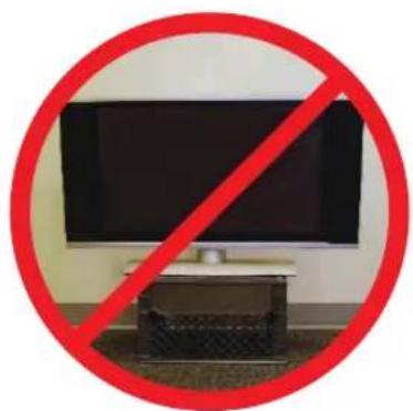
- Flat panel displays that are inappropriately situated on dressers, bookcases, shelves, desks, speakers, chests or carts may fall over and cause injury.
THIS MANUFACTURER CARES!
- The consumer electronics industry is committed to making home entertainment enjoyable and safe.
TUNE INTO SAFETY
- One size does NOT fit all. Follow the manufacturer's recommendations for the safe installation and use of your flat panel display.
- Carefully read and understand all enclosed instructions for proper use of this product.
- Don't allow children to climb on or play with furniture and television sets.
- Don't place flat panel displays on furniture that can easily be used as steps, such as a chest of drawers.
- Remember that children can become excited while watching a program, especially on a "larger than life" flat panel display. Care should be taken to place or install the display where it cannot be pushed, pulled over, or knocked down.
- Care should be taken to route all cords and cables connected to the flat panel display so that they cannot be pulled or grabbed by curious children.
WALL MOUNTING: IF YOU DECIDE TO WALL MOUNT YOUR FLAT PANEL DISPLAY, ALWAYS:
- Use a mount that has been recommended by the display manufacturer and/or listed by an independent laboratory (such as UL, CSA, ETI).
- Follow all instructions supplied by the display and wall mount manufacturers.
- Be sure to follow the installation guide supplied with the Wall-Mount Bracket when installing the TV. To complete the installation, please contact wall-mount manufacturer.
- Make sure that the wall where you are mounting the display is appropriate. Some wall mounts are not designed to be mounted to walls with steel studs or old cinder block construction. To complete the installation, please contact wall-mount manufacturer.
- A minimum of two people are required for installation. Flat panel displays can be heavy.
natural_image
Prohibition symbol showing a TV with a red prohibition sign, no text or symbols present
CEA
Consumer Electronics Association
www.CE.org/safety
Important Safety Instructions

CAUTION
RISK OF ELECTRIC SHOCK DO NOT OPEN

TO REDUCE THE RISK OF ELECTRIC SHOCK, DO NOT REMOVE COVER (OR BACK). NO USER-SERVICEABLE PARTS INSIDE. REFER SERVICING TO QUALIFIED SERVICE PERSONNEL.

- Read these instructions.
- Keep these instructions.
- Heed all warnings.
- Follow all instructions.
- Do not use this apparatus near water.
- Clean only with dry cloth.
- Do not block any ventilation openings. Install in accordance with the manufacturer's instructions.
- Do not install near any heat sources such as radiators, heat registers, stoves, or other apparatus (including amplifiers) that produce heat.
- Do not defeat the safety purpose of the polarized or grounding-type plug. A polarized plug has two blades with one wider than the other. A grounding type plug has two blades and a third grounding prong. The wide blade or the third prong are provided for your safety. If the provided plug does not fit into your outlet, consult an electrician for replacement of the obsolete outlet.
- Protect the power cord from being walked on or pinched particularly at plugs, convenience receptacles, and the point where they exit from the apparatus.
- Only use attachments/accessories specified by the manufacturer.
- Use only with cart, stand, tripod, bracket, or table specified by the manufacturer, or sold with the apparatus. When a cart is used, use caution when moving the cart/apparatus combination to avoid injury from tip-over.
- Unplug this apparatus during lightning storms or when unused for long periods of time.
- Refer all servicing to qualified service personnel. Servicing is required when the apparatus has been damaged in any way, such as power-supply cord or plug is damaged, liquid has been spilled or objects have fallen into the apparatus, the apparatus has been exposed to rain or moisture, does not operate normally, or has been dropped.
- To reduce the risk of fire or electric shock, do not expose this apparatus to rain or moisture. The apparatus shall not be exposed to dripping or splashing and that objects filled with liquids, such as vases, shall not be placed on apparatus.
- To prevent injury, this apparatus must be securely attached to the wall in accordance with the installation instructions.

The lightning flash with arrowhead symbol, within an equilateral triangle is intended to alert the user to the presence of uninsulated dangerous voltage within the product's enclosure that may be of sufficient magnitude to constitute a risk of electric shock.

The exclamation point within an equilateral triangle is intended to alert the user to the presence of important operating and maintenance (servicing) instructions in the literature accompanying the appliance.

AC voltage: This symbol indicates that the rated voltage marked with the symbol is AC voltage.
- The MAINS plug used as the disconnect device. The disconnect device shall remain readily operable.
- Keep your TV away from moisture. Do not expose your TV to rain or moisture. If water penetrates into your TV, unplug the power cord and contact your dealer. Continuous use in this case may result in fire or electric shock.
- Do not expose batteries to excessive heat such as sunshine, fire or the like.
- Danger of explosion if battery is incorrectly replaced. Replace only with the same or equivalent type.
- Apparatus shall not be exposed to dripping or splashing and no objects filled with liquids, such as vases, shall be placed on the apparatus.
22. ⚠ WARNING
This product can expose you to chemicals including [Both Styrene and BPA] which are known to the State of California to Cause Cancer and Reproductive Harm. For more information go to www.P65Warnings.ca.gov.
CONDENSATION:
Moisture will form in the operating section of the unit if the unit is brought from cool surroundings into a warm room or if the temperature of the room rises suddenly. When this happens, unit's performance will be impaired. To prevent this, let the unit stand in its new surroundings for about an hour before switching it on, or make sure that the room temperature rises gradually.
Condensation may also form during the summer if the unit is exposed to the breeze from an air conditioner. In such cases, change the location of the unit.
HOW TO HANDLE THE LCD PANEL:
Do not press hard or jolt the LCD panel. It may cause the LCD panel glass to break and injury may occur. If the LCD panel is broken, make absolutely sure that you do not touch the liquid in the panel. This may cause skin inflammation.
If the liquid gets in your mouth, immediately gargle and consult with your doctor. Also, if the liquid gets in your eyes or touches your skin, consult with your doctor after rinsing for at least 15 minutes or longer in clean water.
POSSIBLE ADVERSE EFFECTS ON LCD PANEL:
If a fixed (non-moving) pattern remains on the LCD Panel for long periods of time, the image can become permanently engrained in the LCD Panel and cause subtle but permanent ghost images. This type of damage is NOT COVERED BY YOUR WARRANTY. Never leave your LCD Panel on for long periods of time while it is displaying the following formats or images:
Safety Precautions
- Fixed Images, such as stock tickers, video game patterns, TV station logos, and websites.
Special Formats that do not use the entire screen. For example, viewing letterbox style (16:9) media on a normal (4:3) display (black bars at top and bottom of screen); or viewing normal style (4:3) media on a widescreen (16:9) display (black bars on left and right sides of screen).
The following symptoms are not signs of malfunction but technical limitation. Therefore we disclaim any responsibility for these symptoms.
- LCD Panels are manufactured using an extremely high level of precision technology, however sometimes parts of the screen may be missing picture elements or have luminous spots.
This is not a sign of a malfunction.
Do not install the LCD Panel near electronic equipment that produces electromagnetic waves. Some equipment placed too near this unit may cause interference.
Effect on infrared devices - There may be interference while using infrared devices such as infrared cordless headphones.
End of life directives
Your TV also contains material that can be recycled and reused. For disposal or recycling information, contact your local authorities or the Electronic Industries Alliance at www.eia.org (for USA), the Electronic Products Recycling Association at http://www.eprassociation.ca (for Canada) to find a recycler in your area.
Non-active pixels
The LCD panel contains almost 3 million thin film transistors, which provide exceptionally sharp video quality. Occasionally, a few non-active pixels may appear on the screen as a fixed black (in the case of a dead pixel), blue, green, or red point. These non-active pixels do not adversely affect the performance of your TV, and are not considered defects.
Power source
WARNING
- Do not use a different power supply cord to plug the TV into an AC outlet. Using a power cord that did not already come with the TV could cause a fire, electrical shock or damage.
- Do not use a power voltage that is different than what Hisense has already specified. This could cause a fire, electrical shock or damage.
- If you do not plan to use this TV for a long time (due to a lengthy trip or some other reason) then be sure to unplug it from the AC outlet.
- Do not plug or unplug the AC cord when your hands are wet. This may cause electrical shock.
- If an outside antenna or cable system is connected with the TV, be sure the antenna or cable system is grounded so as to provide protection against voltage surges and built-up static charges...
No naked flame sources, such as lighted candles, should be placed on the apparatus.
The WiFi Module complies with FCC radiation exposure limits set forth for an uncontrolled environment. This device should be installed and operated with a minimum distance of 20 centimeters between the radiator and your body. (only applicable for Smart TV built-in wireless)
FCC RF Safety Caution Statement
This equipment complies with FCC RF radiation exposure limits set forth for an uncontrolled environment. This equipment must be installed and operated in accordance with provided instructions and must not be co-located or operating in conjunction with any other antenna or transmitter. End-users and installers must be provided with antenna installation instructions and transmitter operating conditions for satisfying RF exposure compliance.
RF Exposure Statement for Canada
The radiated output power of the Wireless Device is below the Industry Canada (IC) radio frequency exposure limits. The Wireless Device should be used in such a manner such that the potential for human contact during normal operation is minimized.
(only applicable for TV with RF port)
WARNING
Never place a television set in an unstable location. A television set may fall, causing serious personal injury or death. Many injuries, particularly to children, can be avoided by taking simple precautions such as:
– Using cabinets or stands recommended by the manufacturer of the television set.
- Only using furniture that can safely support the television set.
- Ensuring the television set is not overhanging the edge of the supporting furniture.
- Not placing the television set on tall furniture (for example, cupboards or bookcases) without anchoring both the furniture and the television set to a suitable support.
- Not placing the television set on cloth or other materials that may be located between the television set and supporting furniture.
– Educating children about the dangers of climbing on furniture to reach the television set or its controls.
If your existing television set is being retained and relocated, the same considerations as above should be applied.
2. Introduction
2.1 Package Contents

WR6CE × 1

Stylus × 2
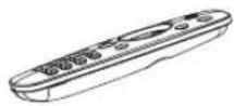
Remote Control
Battery × 2

User Manual of the Device Wall Mount Bracket (Optional)


Wall Mount Bracket
Accessories bag (Optional)

Power Cord (It depends on the models, regions, or countries.)
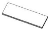
User Manual of Wireless Cast × 1 (Optional)

Wireless Cast (Optional)
NOTE
- The accessories may be different from the list above due to different models, countries/regions, please refer to the actual accessory bag.
2.2 Products View
2.2.1 Front Panel | Control Panel

| Number Item Description | ||
| 1 NFC | When the mobile phone touches the device, it can achieve screen sharing through mobile phone NFC function. | |
| 2 USB | It is a USB interface, which can be used as the media playback interface of the device and the USB interface of embedded OPS module. It is also the USB used to synchronize the USB-A dongle | |
| 3 HDMI IN | The front HDMI interface allows digital audio and video signals to be transmitted using a single cable without compression. HDMI supports multi-channel digital audio, and can be connected to external devices with HDMI port, such as computer host, set-top box, Blu-ray player, A/V device, etc. | |
| 4 Type-C | It is a full-featured Type-C interface, which supports audio, video, and file transmission. | |
| 5 | Standby button | When the device is on, short press the button to turn off the screen, long press the button to go into standby mode.When the screen is off, press the button to open the screen, and when the device is on standby, press the button to start.The indicator light displays the state of power on or standby:When the device is on, the light is blue.When standby, the light is red.When the device with OPS module is turned on, the light is green. |
2.2.2 Rear Panel | I/O Panel
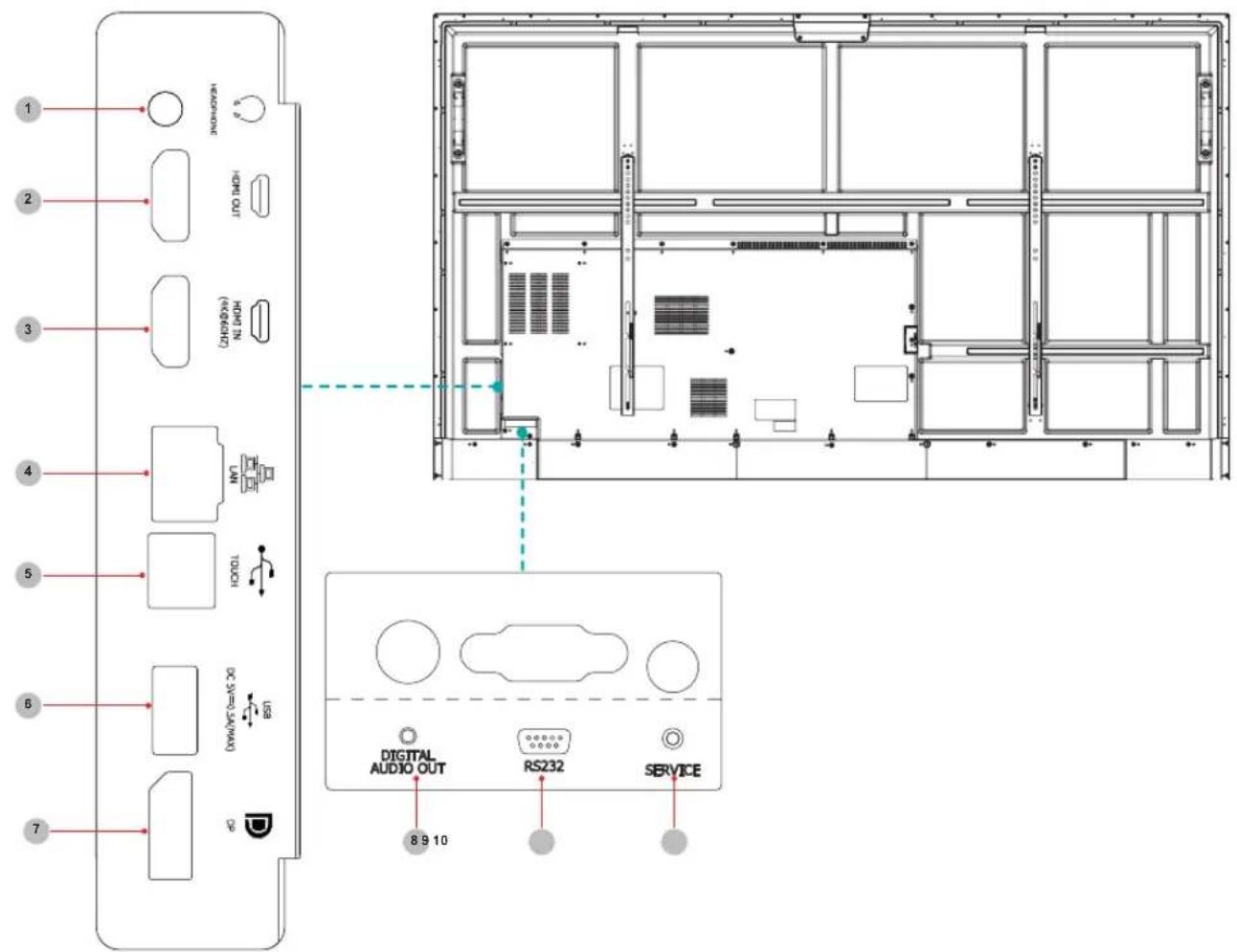
| Number | Port Description | |
| 1 | HEADPHONE Audio out to | Headphones |
| 2 | HDMI OUT HDMI signal output, connect to an external device with HDMI input port | |
| 3 | HDMI IN HDMI signal input, connect to PC with HDMI output port, set-top box, or other video device | |
| 4 | LAN Standard RJ45 Internet connection interface | |
| 5 | TOUCH Touch signal output to external PC | |
| 6 | USB 2.0 Connect USB devices such as hard disks, keyboard, mouse, etc. [5V DC/0.5A] | |
| 7 | DP | DP signal input, connect to PC with DP output |
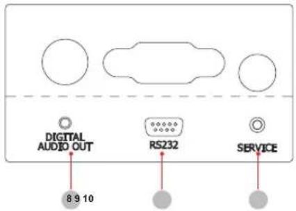
| 8 | DIG TAL AUDIO OUT | Connect to power amplifier via coaxial port, then connect power amplifier to speaker |
| 9 | RS232 | Serial interface, used for mutual transfer of data between devices |
| 10 | SERVICE For factory commissioning, don't insert any cables | |
2.3 Remote Control
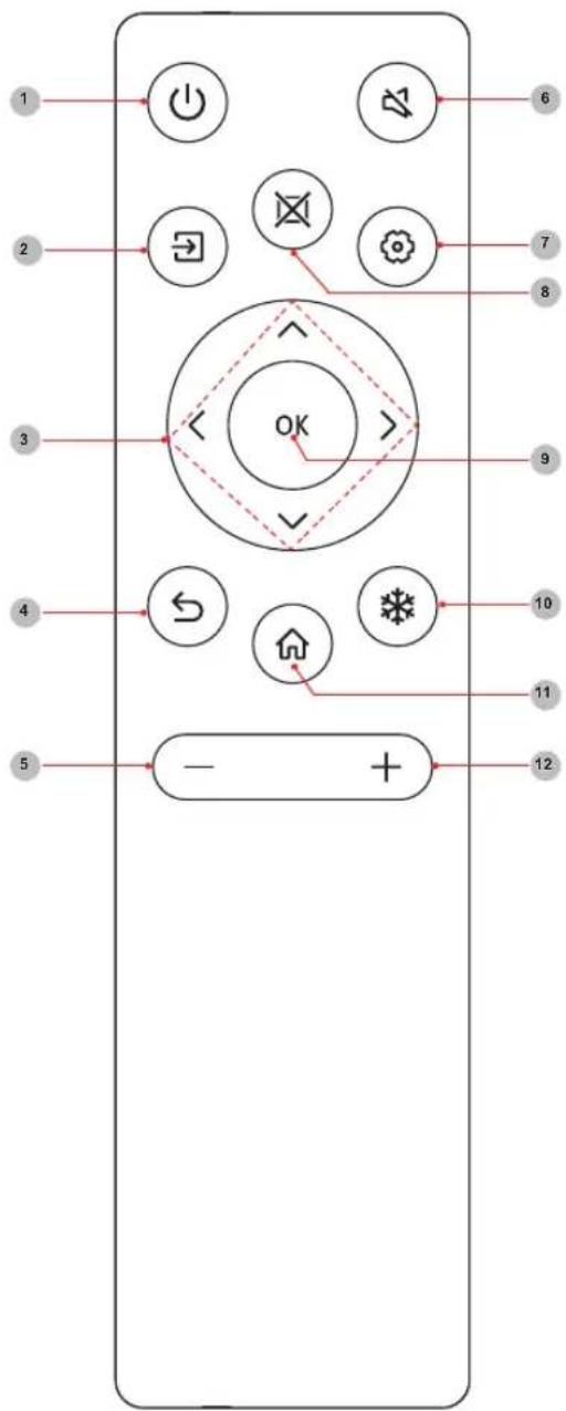
| Number | Description |
| 1 Power | Enter/exit standby |
| 2 Source | Switching signal source |
| 3 ▲/ | Move focus up/down◄/►Move focus left/right |
| 4 Back | Back to previous menu |
| 5 Volume down (-) | |
| 6 Mute | Activate/exit mute state |
| 7 Setting | Open the Settings menu |
| 8 Blank | Switch On/Off screen |
| 9 OK | Confirm operation |
| 10 Freeze | Once click: Keep the current screen |
| 11 Home | Enter home page |
| 12 Volume up (+) | |
Battery replacement method
- Disconnect the battery cover from the remote control at the battery cover buckle and open the battery cover.
- Insert two AAA 1.5V alkaline batteries. Note that the positive (+) and negative (-) terminals of the batteries must match the positive (+) and negative (-) terminals in the battery case.
- Close the battery cover from top to bottom until it is fully aligned with the remote control.
Precautions
- If the remote control is not working properly, is unstable, or can't control the device, please replace the batteries.
- If you do not use the remote control for a long time or the battery is exhausted, remove the battery. (Waste batteries pollute the environment and must be handled properly.)
- In order to achieve the best remote control effect, please point the black launch window on the back of the remote control at the indicator light of the device.
- Discard batteries in a designated disposal area. Do not throw them into a fire.
- Remove old batteries immediately to prevent them from leaking into the battery compartment.
- Battery chemicals can cause a rash. If the batteries leak, clean the battery compartment with a cloth. If chemicals touch your skin then wash it immediately.
- Do not mix old and new batteries.
- Do not mix alkaline, standard (carbon-zinc) or rechargeable (NiCd, NiMH, etc.) batteries.
- Do not continue using the remote if it gets warm or hot.
- If any of these issues occur, call our Support Center immediately on the support website.
Effective range
- Remote control distance: The distance from the front of the remote control is valid within 8m.
- Remote control angle: With the remote control receiving window of the device as the apex, the angle in horizontal direction at the distance of 6m is at least ±30^ , and the angle in vertical direction is at least ±15^ .
3. Installation Guide
3.1 Precautions for Installation
As shown in the figure below, leave a ventilation space around the device.
When mounted on the wall:
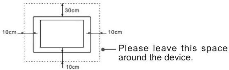
- Do not install the device as shown below.
Hinder air circulation

Insufficient ventilation will overheat the device and may cause damage to the device and even fire.
3.2 Wall Mount Kit Specifications (VESA)
NOTE: Please follow the instructions in the wall mount installation guide to install your wall mount or mobile mount bracket. If attaching to other building materials, please contact your nearest dealer.

| Model VESA Spec. (A × B) Standard Screw (C × D) Quantity | |||
| 65WR6CE | 600 × 400mm M8 × 25 4 | ||
| 75WR6CE | 600 × 600mm M8 × 25 4 | ||
| 86WR6CE | 1000 × 600mm M8 × 25 4 | ||

NOTE: Do not use screws that are longer than the standard dimension, as they may cause damage to the inside of the display.
3.3 Installing the OPS (Optional)
Before installing and operating OPS, it is required to carefully read the instructions that come with OPS computer and this instruction manual.
Installation Sequence
- The touch screen is set to the "off" state, and the indicator light is off.
- The operator wears anti-static gloves and takes out OPS computer.
- Assembly steps for OPS computer:
(1) This product is compatible with OPS-C Plus interface computer, and assembly instructions are as follows:
Note: Different models of touch screen and computer brackets have different shapes, but the assembly method is the same.

① is located at the computer bracket and the connecting screw of computer, which can be matched with ②.
② It is the hanging nose, where OPS-C Plus computer is assembled with fastening screws. There are a total of two hanging noses, which are placed in OPS-C Plus computer package as an accessory and there is need to assemble them on OPS-C Plus computer in advance.
Before assembling the computer, please check the shape of OPS-C Plus plug-in terminal, which should meet the requirements in the following Figure:

Instructions for OPS terminal assembly
tolerances
(2) Instructions for assembly routes:
a. Place the touch screen vertically or place the touch screen face-down stably, and make sure there is enough room for operation around the computer bracket on the back of screen.
b. Remove M3x6 screw reserved at ① for standby application.
c. Insert OPS-C Plus computer into the computer bracket along the route as shown in the Figure until ② and ① are in close contact.
d. Apply spare screws M3x6 to fasten the computer (some computer models come with screws that can be used directly), tightening torque: 0.5 N·m<M<0.8N·m.
(3) The pattern after assembly is as follows:

Schematic diagram after the assembly of OPS-C Plus computer
(4) Precautions after assembly:
a. After the computer is installed, ② and ① should be closely fitted (same on the left and right sides).
b. Screws are firmly and securely fastened. The computer doesn't shake.
- After the above steps are completed, screen can be switched on. After startup, OPS computer is started, and the operating system interface is performed to confirm that there is no abnormality. The first startup is completed.
4. Making Connections

flowchart
graph TD
    A["HEADPHONE"] --> B["HOEM OUT"]
    B --> C["HOEM IN (4KB/60HZ)"]
    C --> D["LAN"]
    D --> E["TOUCH"]
    E --> F["USB"]
    F --> G["DC SV=0.5A(MAX)"]
    G --> H["DP"]
    H --> I["7643215"]
| Number Port Description | ||
| 1 HEADPHONE Audio out to | Headphones | |
| 2 HDMI OUT HDMI signal output, connect to an external device with HDMI input port | ||
| 3 HDMI IN HDMI signal input, connect to PC with HDMI output port, set-top box, or other video device | ||
| 4 LAN Standard RJ45 Internet connection interface | ||
| 5 | TOUCH | Touch signal output to external PC |
| 6 | USB 2.0 | Connect USB devices such as hard disks, keyboard, mouse, etc. [5V DC/0.5A] |
| 7 | DP | DP signal input, connect to PC with DP output |
| 8 | DIGITAL AUDIO OUT | Connect to power amplifier via coaxial port, then connect power amplifier to speaker |
| 9 | RS232 | Serial interface, used for mutual transfer of data between devices |
| 10 SERVICE For factory commissioning, don't insert any cables | ||
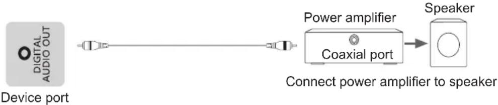
Connect to external audio device
Digital audio output: connect to power amplifier via coaxial port, then connect power amplifier to speaker.
flowchart
graph LR
    A["Device port"] --> B["Coaxial port"]
    B --> C["Power amplifier"]
    C --> D["Speaker"]
    style A fill:#f9f,stroke:#333
    style D fill:#ccf,stroke:#333
Connect to DP interface device

flowchart
graph LR
    A["Device port"] --> B["USB cable"]
    B --> C["USB cable"]
    C --> D["PC"]
NOTE
The supported signal formats of the DP port refer to Chapter 8 Appendix.
Part of lower version DP cables may cause screen flashing or no displaying, please try to use cables in latest version and high quality.
Part of input RGB signals may occur low quality situations in low or high brightness mode. To adapt the picture quality, you can press the ⚙ Settings button on the remote control, select Dynamic Range in the Picture menu, and then select All.
Connect to HDMI input
Connect the HDMI input connector of the device to the HDMI output port of an external device.

NOTE
The supported signal formats of the HDMI port refer to Specifications.
Connect to HDMI output
Connect the HDMI output connector of the device to the HDMI input port of an external device.

NOTE
When using it as a screen monitor, carefully read precautions for still image of the device.
Connect to TOUCH interface device
It is the touch screen interface used for an external PC as touch host. In both the HDMI and DP channels, the device is used as a touch unit by default
When connecting, USB cables not longer than 1 meter should be used to connect with the external PC.

▶ Use of external interface of touch screen and selection of touch unit
This device has a TOUCH port. When you need to use an external PC as the touch unit and signal source unit, you can connect USB ports of the device and PC with a USB cable (both ends are male connections), connect the PC to the device with a signal cable (HDMI and DP cable), and switch the signal source to that channel. At this time, the touch screen can be connected to the corresponding unit, and the touch screen can be used to perform touch operations on the unit.
On the home page, the device is used as the touch unit. In HDMI, OPS and DP channels, the device is used as the touch unit by default. When the external unit is connected and powered on, and the USB cable is connected to the external unit (OPS does not need a USB cable), the touch unit is changed to the external PC.
To operate the device, you can use the five-point touch method to call out the soft control menu and operate the device. After operation, tap any area out of the soft control menu of the device to hide the soft control menu. Then you can continue to operate the external PC, and the current channel is set as the touch input channel.
In the OPS channel, you can touch OPS without the soft control menu.
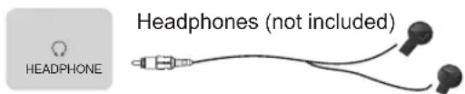
HEADPHONE Connect Headphone for audio out of the screen.
Device port
ATTENTION
Excessive sound pressure from earphones and headphones can cause hearing loss.
NOTE
Please make sure that the headphones you plug in is without microphone function, or it may not be supported.
Connect to a USB interface device
The total current of all the USB output ports of the device when connected to external devices at the same time mustn't exceed 2500mA, or else the device failure caused by overcurrent isn't covered by the warranty.

Device port
NOTE
This device is connected to wireless keyboard and mouse devices. If there is any insensitivity phenomenon during use, you can try to change the wireless receiver to another USB port, or use a USB extension cord to connect the wireless receiver in order to enhance the receiving range.
Connect to a network
Enter the Settings menu and select the Network item.
WIFI

The device can receive network signals directly through a Wireless router
- The available wireless network list is automatically displayed when WIFI is selected.
- Select an available network, enter the password, and tap Connect. If the selected network is not encrypted, you can connect directly.
- If the network you want to connect to is not displayed in the list, tap Refresh to display more networks. If the network you want is still not displayed after this operation, tap Add Network and enter the network name manually, select the corresponding encryption method according to router settings, enter the password, and tap Confirm.
Ethernet

flowchart
graph LR
    A["LAN"] --> B["Router"]
    B --> C["Network port output"]
    B --> D["Network port input"]
    C --> E["Network port in the wall"]
Device port
- Ethernet: auto
The device automatically obtains an IP address and connects to the network. If failure, repeat the operation again or choose Ethernet:manual.
- Ethernet: manual
Manually enter the IP Address, Subnet Mask, DNS Server and Gateway.
Connect to the OPS interface device
OPS (Open Pluggable Specification) is the interface specification developed by INTEL which is applicable to embedded computer module products. With this interface, the screen can be connected to the device in compliance with OPS interface specification, which is short for OPS module. You can buy the module and conduct secondary development in accordance with your requirements.
This product can provide the OPS module with 18V ± 0.5V (4.74A MAX) power supply.
NOTE
After installing OPS module, when the signal source is in computer channel, device touch screen regards OPS as the touch unit by default. After TOUCH is connected with an external computer, the external computer is used as the touch unit. At this time, the signal source should be switched to the channel of the external computer for using the touch functionality.
You should purchase the OPS module which is applicable to the size of the device OPS. The size of OPS refers to the following figure:

- Switching on/off the OPS
After inserting OPS to the device, you turn on the device, change the signal source to enter OPS and stays on the OPS syetem interface. When you turn off the device, you should use the standby button to go into standby mode, the OPS module is switched off, and then you shut off the device.
5. Getting Started
5.1 Power On/Off

- Connect the power cord of the device to a 100V to 240V AC outlet.
- Press the standby button [ ☑] on the remote control in the power on state to switch the device to standby; to resume normal watch, simply press the standby button [ ☑] on the remote control again.
Note:
- When the AC power is turned off, wait at least 5 seconds before turning it on again in order to prevent problems of the device.
5.2 Using Gestures

In any scene on the screen, touch the screen with five fingers to call up the shortcut menu.
| Number Function Description | ||
| 1 Annotation All-channel annotation | ||
| 2 Homepage One-click to return to Android homepage | ||
| 3 Signal source Open the list of signal source | ||
| 4 Volume Call out the volume adjustment interface | ||
| 5 Return Return to the previous operation | ||
| 6 Lock screen The screen is locked and it can't be operated by touch or remote control | ||
| 7 | Setting | Call out the setting page of the whole machine |
| 8 | Windows | Switch to Windows when equipped with OPS |
| 9 | Screenshot | Screen Capture |
6. Serial Protocol
Serial port status
The device can receive the serial port command sent by the external controller or OPS of the device.
Refer to the following table for the specific command protocol:
- Baud rate: 9600
- Control section: PC → The device
- Response section: Android → PC
| Protocol header | Length | Command code ID | Data Verify | Protocol tail | ||
| Screen on/off | OnPC to device | DD FF 00 07 C1 31 00 00 01 00 F6 BB CC | ||||
| OnDevice to PC | AB AB 00 07 C1 31 00 00 01 00 F6 CD CD | |||||
| OffPC to device | DD FF 00 07 C1 31 00 00 01 01 F7 BB CC | |||||
| OffDevice to PC | AB AB 00 07 C1 31 00 00 01 01 F7 CD CD | |||||
| Current Signal Source Query | PC to device | DD FF 00 06 C1 | 1A | 00 00 01 | DC BB CC | |
| Device to PC | AB AB 00 09 C1 | 1A | 00 00 01 | XX XX XX | XX CD CD | |
| Remark | Data: XX XX XX05 03 02: OPS05 03 00: Front HDMI05 03 01: Side HDMI05 03 03: Type-C05 03 04: DP | |||||
| Software Version Query | PC to device | DD FF 00 06 C1 1B 00 00 01 | DD BB CC | |||
| Device to PC | AB AB 00 09 C1 1B 00 00 01 | XX XX XX | XX CD CD | |||
| Remark | The first XX is the Year.The second XX is the Month.The third XX is the Day. | |||||
| Set Time (Y/M/D) | PC to device | DD FF 00 09 C1 1C | 00 00 01 | XX XX XX | XX BB CC | |
| Device to PC | AB AB 00 09 C1 1C | 00 00 01 | XX XX XX | XX CD CD | ||
| Remark | The first XX is the Year.The second XX is the Month.The third XX is the Day.If set failures, these three XX return FF. | |||||
Serial Protocol
| Protocol header | Length C | Command code ID D | Data Verify | Protocol tail | ||||||||||
| Set Time (H/M/S) | PC to device | DD | FF 00 | 09 C | 1 1D | 00 00 | 01 | XX XXXX | XX BB CC | |||||
| Device to PC | AB | AB 00 | 09 C | 1 1D | 00 00 | 01 | XX XXXX | XX CD CD | ||||||
| Remark | The first XX is the Hour.The second XX is the Minute.The third XX is the Second.If set failures, these three XX return FF. | |||||||||||||
| Reboot Screen | PC to device | DD | FF 00 | 06 C | 1 1E | 00 00 | 01 D | 8 BB | CC | |||||
| Device to PC | AB | AB 00 | 06 C | 1 1E | 00 00 | 01 D | 8 CD | CD | ||||||
| Signal Source Selection | PC to device | DD | FF 00 | 07 C | 1 08 | 00 00 | 01 XX | XX BB CC | ||||||
| Device to PC | AB | AB 00 | 07 C | 1 08 | 00 00 | 01 XX | XX CD CD | |||||||
| Remark | Data: XX04: OPS05: Front HDMI06: Side HDMI0B: Type-C0C: DP | |||||||||||||
| Screen on/off Query | PC to device | DD | FF 00 | 06 C | 1 32 | 00 00 | 01 | F4 BB CC | ||||||
| Device to PC | AB | AB 00 | 07 C | 1 32 | 00 00 | 01 XX | XX CD CD | |||||||
| Remark | Data: XX00 is the screen off state.01 is the screen on state. | |||||||||||||
Serial Protocol
| Protocol header | ID Length Command code Protocol tail | ||||||||||
| Switch on/off | On PC to device | DD FF 01 04 | A1 00 00 00 BB CC | ||||||||
| On Device to PC | AB AB 01 04 | A1 00 00 00 CD CD | |||||||||
| Off PC to device | DD FF 01 04 | A1 01 00 00 BB CC | |||||||||
| Off Device to PC | AB AB 01 04 | A1 01 00 00 CD CD | |||||||||
| Volume Control | PC to device | DD FF 01 04 | A1 07 00 XX BB CC | ||||||||
| Device to PC | AB AB 01 04 | A1 07 00 XX CD CD | |||||||||
| Remark XX is the volume value. | |||||||||||
| Brightness Control | PC to device | DD FF 01 04 | A1 08 00 XX BB CC | ||||||||
| Device to PC | AB AB 01 04 | A1 08 00 XX CD CD | |||||||||
| Remark XX is the brightness value. | |||||||||||

NOTE
- Verify is the exclusive OR of Length, Command code, ID and Data.
- All data are hexadecimal values.
- For all commands received by the device, the protocol header needs to be changed to AB AB and the protocol tail needs to be changed to CD CD when returning to the PC.
- Precautions for control terminal programming: For the power-on command, AB AB 01 04 A1 00 00 00 CD CD are returned after the power-on action is executed; if the command is not received, the power-on command needs to be sent again. After Android is turned on, the PC will receive AB AB 01 04 A1 00 00 00 CD CD again, and then the PC can send a control command to the device. If the correct command is not returned after any command is sent, the command should be sent again at least after 500ms.
- In Android standby state, the device only supports startup commands.
7. Appendix
7.1 Specification
Features, appearance and specifications are subject to change without notice.
| Product name Hisense Interactive Digital Board | ||
| Model 65WR6CE | ||
| Size(mm) (W×H×D) excluding base 1488 x 889 x 95 | ||
| Weight(kg) excluding base 33.0 | ||
| Visual picture diagonal size (cm) 164 | ||
| Power supply 100-240V 50/60Hz 3A ~ | ||
| Wireless LAN Module specifications | Model TX7663BU58T TX7921AU64T | |
| Frequency Range | 2.4~2.4835GHz5.15~5.85GHz | |
| Output Power (Max.) | 2.4G 17dBm5G 15dBm | |
| Display resolution 3840 × 2160 | ||
| Sound power 15W + 15W | ||
| Executive standard Q/0202RSR 620 | ||
| Environmental conditions | Operating temperature 5°C ~ 35°COperating humidity 20% ~ 80%RHAtmospheric pressure 86kPa ~ 106kPa | |
| Product name Hisense Interactive Digital Board | ||
| Model 75WR6CE | ||
| Size(mm) (W×H×D) excluding base 1710 × 1014 × 100 | ||
| Weight(kg) excluding base 45.8 | ||
| Visual picture diagonal size (cm) 189 | ||
| Power supply 100-240V 50/60Hz 3.5A ~ | ||
| Wireless LAN Module specifications | Model TX7663BU58T TX7921AU64T | |
| Frequency Range | 2.4~2.4835GHz5.15~5.85GHz | |
| Output Power (Max.) | 2.4G 17dBm5G 15dBm | |
| Display resolution 3840 × 2160 | ||
| Sound power 15W + 15W | ||
| Executive standard Q/0202RSR 620 | ||
| Environmental conditions | Operating temperature 5°C ~ 35°COperating humidity 20% ~ 80%RHAtmospheric pressure 86kPa ~ 106kPa | |
Appendix
| Product name Hisense Interactive Digital Board | |||
| Model 86WR6CE | |||
| Size(mm) (W×H×D) excluding base 1955 x 1151 x 99 | |||
| Weight(kg) excluding base | 54.5 | ||
| Visual picture diagonal size (cm) | 217 | ||
| Power supply | 100-240V ~50/60Hz 4.3A | ||
| Wireless LAN Module specifications | Model | TX7663BU58T | TX7921AU64T |
| Frequency Range | 2.4~2.4835GHz5.15~5.85GHz | ||
| Output Power (Max.) | 2.4G 17dBm5G 15dBm | ||
| Display resolution | 3840 × 2160 | ||
| Sound power | 15W + 15W | ||
| Executive standard | Q/0202RSR 620 | ||
| Environmental conditions | Operating temperature 5°C ~ 35°COperating humidity 20% ~ 80%RHAtmospheric pressure 86kPa ~ 106kPa | ||
The supported video formats are as follows:
| Encapsulation | Video decoding | Audio decoding | |||
| Type Resolution(Max) | Bit rate(Max) | Frame rate(Max) | |||
| .avi Xvid 1 | 920 × 1080 | 50Mbps 30fps | Dolby Audio, MPEG1(Layer1,2,3) | ||
| .avi .mpg .ts | MPEG2 1920 | × 1080 80Mbps | 30fps | Dolby Audio, MPEG1(Layer1,2,3) | |
| .ts .mkv .avi .mp4 .flv | H.264 3840 | × 2160 160Mbps | 30fps | Dolby Audio, AAC, MPEG1(Layer1,2,3) | |
| .avi .mpg .mov | MPEG4 1920 | × 1080 50Mbps | 30fps | Dolby Audio, MPEG1(Layer1,2,3) | |
| .mkv .mp4 .ts | H.264 3840 | × 2160 160Mbps | 30fps | Dolby Audio, AAC, MPEG1(Layer1,2,3) | |
| .ts .mkv .mp4 | H.265 3840 | × 2160 160Mbps | 60fps | Dolby Audio, AAC, MPEG1(Layer1,2,3) | |
Dolby Audio: Support Dolby Digital, Dolby Digital Plus, Dolby AC4, and Dolby TrueHD.
NOTE
Formats listed above may not all supported by the device as video making tools are not unified.
Appendix
| Signal formats supported by HDMI port | |
| RGB/60Hz 640 × 480, | 800 × 600, 1024 × 768 |
| YUV/50Hz 576i, 576p, | 720p, 1080i, 1080p |
| YUV/60Hz 480i, 480p, | 720p, 1080i, 1080p |
| YUV/24Hz 25Hz 30Hz 3840 | × 2160, 4096 × 2160 |
| YUV420/50Hz 60Hz 3840 x | 2160, 4096 × 2160 |
| YUV444/50Hz 60Hz 3840 x | 2160, 4096 × 2160 |
| RGB444/50Hz 60Hz 3840 x | 2160, 4096 × 2160 |
NOTE
HDMI standard and HDMI enhance are supported by the device. HDMI standard is the default, which only supports part of formats listed above. HDMI enhance supports all formats listed above. If HDMI enhance is needed, you can tab menu under HDMI Version and select HDMI enhance.
| Signal formats supported by DP port | |
| RGB/60Hz 640 × 480, | 800 × 600, 1024 × 768 |
| YUV/50Hz 576p, 720p, | 1080i, 1080p |
| YUV/60Hz 480p, 720p, | 1080i, 1080p |
| YUV/24Hz 25Hz 30Hz 3840 | x 2160, 4096 x 2160 |
| YUV444/50Hz 60Hz 3840 x | 2160, 4096 × 2160 |
| RGB444/50Hz 60Hz 3840 x | 2160, 4096 × 2160 |
7.2 Other Infomation
Recycling/Licenses
WEEE (Waste Electronic Electric Equipment)
European Directive 2012/19/EU
This symbol on the product or on its packaging indicates that this product must not be disposed of with your household waste. Instead, it is your responsibility to dispose of your waste equipment by handing it over to a designated collection point for the recycling of waste electrical and electronic equipment. The separate collection and recycling of your waste equipment at the time of disposal will help to conserve natural resources and ensure that it is recycled in a manner that protects human health and the environment. For more information about where you can drop off your waste equipment for recycling, please contact your local city office, your household waste disposal service or the shop where you purchased the product.
Batteries
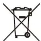
In accordance with the Battery Directive, used batteries should not be disposed of in the domestic waste. Dispose your batteries in the collection containers specific for this purpose in retail stores.
ROHS (Restriction of Hazardous Substance) European Directive 2011/65/EU

This European directive limits the use of dangerous and hazardous substances which are difficult to recycle.
This allows recycling easily the EEE and contributes to the safeguard of the environment.
Substances included in this product match to the RoHS directive.

The terms HDMI and HDMI High-Definition Multimedia Interface, and the HDMI Logo are trademarks or registered trademarks of HDMI Licensing Administrator, Inc. in the United States and other countries.
WARNING: This set must not be opened unless by a qualified technician.
The device set may fall, causing serious personal injury or death.
To prevent injury, this device set must be securely attached to the wall in accordance with the installation instructions.
7.3 Certification and Compliance
FCC Notice
This equipment has been tested and found to comply with the limits for a Class A digital device, pursuant to part 15 of the FCC Rules. These limits are designed to provide reasonable protection against harmful interference when the equipment is operated in a commercial environment. This equipment generates, uses, and can radiate radio frequency energy and, if not installed and used in accordance with the instruction manual, may cause harmful interference to radio communications. Operation of this equipment in a residential area is likely to cause harmful interference in which case the user will be required to correct the interference at his own expense.
NOTE: The manufacturer is not responsible for any radio or Screen interference caused by unauthorized modifications to this equipment. Such modifications could void the user's authority to operate the equipment.
The Wi-Fi Module complies with FCC radiation exposure limits set forth for an uncontrolled environment. This device should be installed and operated with a minimum distance of 20 centimeters between the radiator and your body.
This equipment complies with radio frequency exposure limits set forth by the Innovation, Science and Economic Development Canada for an uncontrolled environment.
This equipment should be installed and operated with a minimum distance of 20 cm between the device and the user or bystanders.
This device must not be co-located or operating in conjunction with any other antenna or transmitter.
This device complies with Industry Canada's licence-exempt RSSs. Operation is subject to the following two conditions:
(1) This device may not cause interference; and
(2) This device must accept any interference, including interference that may cause undesired operation of the device.
Declaration of Conformity
Trade Name: Hisense
Model: 65WR6CE / 75WR6CE / 86WR6CE
Responsible Party: Hisense USA Corporation
Address: 7310 McGinnis Ferry Road, Suwanee, GA 30024
Telephone Number: 678-318-9060
7.4 EU Declaration of conformity (DOC)
EU Declaration of conformity (DoC)
Unique identification of this DoC: HCD-DOC-20220808-001
We, Declare under our sole responsibility that the product:
Product Name: Hisense Interactive Digital Board
Trade Name: Hisense
Model: 65WR6CE
To which this declaration relates is in conformity with the essential requirements and other relevant requirements of the radio equipment directive(2014/53/EU), Ecodesign Directive(2009/125/EC)& Regulation (EU) 2019/2021, ROHS Directive (2011/65/EU). The product is in conformity with the following standards and/or other normative documents:
Health & Safety (Art. 3(1)(a)): EN IEC62311:2020
EN62368-1:2014+A11:2017
EMC (Art. 3(1)(b)): EN55032:2015+A11:2020
EN55035:2017+A11:2020
EN IEC 61000-3-2:2019
EN61000-3-3:2013+A1:2019
EN301489-1 V2.2.3:2019
EN301489-17 V3.2.4:2020
Spectrum (Art. 3(2)): EN300328 V2.2.2:2019
EN301893 V2.1.1:2017
ErP: Transitional Test Method for Ecodesign and Energy Labelling requirements for electronic displays
RoHS: IEC 63000:2018
Software * 65.V0000.WR6.CE.00.01A.M0727
*The company reserves the right to install updated Software versions to improve the performance of the appliance.
Place and date of issue (of this DoC): QingDao 2022/08/01
Signed by or for the manufacturer: Hisense Commercial Display Co., Ltd.
Address: No.218, Qianwangang Road, Economy& Technology Development Zone, Qingdao, China
Title: Product manager
Name (in print): Gengqingsong
Geng Qingsong
EU Declaration of conformity (DoC)
Unique identification of this DoC: HCD-DOC-20220808-002
We, Declare under our sole responsibility that the product:
Product Name: Hisense Interactive Digital Board
Trade Name: Hisense
Model: 75WR6CE
To which this declaration relates is in conformity with the essential requirements and other relevant requirements of the radio equipment directive(2014/53/EU), Ecodesign Directive(2009/125/EC)& Regulation (EU) 2019/2021, ROHS Directive (2011/65/EU). The product is in conformity with the following standards and/or other normative documents:
Health & Safety (Art. 3(1)(a)): EN IEC62311:2020
EN62368-1:2014+A11:2017
EMC (Art. 3(1)(b)): EN55032:2015+A11:2020
EN55035:2017+A11:2020
EN IEC 61000-3-2:2019
EN61000-3-3:2013+A1:2019
EN301489-1 V2.2.3:2019
EN301489-17 V3.2.4:2020
Spectrum (Art. 3(2)): EN300328 V2.2.2:2019
EN301893 V2.1.1:2017
ErP: Transitional Test Method for Ecodesign and Energy Labelling requirements for electronic displays
RoHS: IEC 63000:2018
Software * 75.V0000.WR6.CE.00.01A.M0727
*The company reserves the right to install updated Software versions to improve the performance of the appliance.
Place and date of issue (of this DoC): QingDao 2022/08/01
Signed by or for the manufacturer: Hisense Commercial Display Co., Ltd.
Address: No.218, Qianwangang Road, Economy& Technology Development Zone, Qingdao, China
Title: Product manager
Name (in print): Gengqingsong
Geng Qingsong
EU Declaration of conformity (DoC)
Unique identification of this DoC: HCD-DOC-20220808-003
We, Declare under our sole responsibility that the product:
Product Name: Hisense Interactive Digital Board
Trade Name: Hisense
Model: 86WR6CE
To which this declaration relates is in conformity with the essential requirements and other relevant requirements of the radio equipment directive(2014/53/EU), Ecodesign Directive(2009/125/EC)& Regulation (EU) 2019/2021, ROHS Directive (2011/65/EU). The product is in conformity with the following standards and/or other normative documents:
Health & Safety (Art. 3(1)(a)): EN IEC62311:2020
EN62368-1:2014+A11:2017
EMC (Art. 3(1)(b)): EN55032:2015+A11:2020
EN55035:2017+A11:2020
EN IEC 61000-3-2:2019
EN61000-3-3:2013+A1:2019
EN301489-1 V2.2.3:2019
EN301489-17 V3.2.4:2020
Spectrum (Art. 3(2)): EN300328 V2.2.2:2019
EN301893 V2.1.1:2017
ErP: Transitional Test Method for Ecodesign and Energy Labelling requirements for electronic displays
RoHS: IEC 63000:2018
Software * 86.V0000.WR6.CE.00.01A.M0727
*The company reserves the right to install updated Software versions to improve the performance of the appliance.
Place and date of issue (of this DoC): QingDao 2022/08/01
Signed by or for the manufacturer: Hisense Commercial Display Co., Ltd.
Address: No.218, Qianwangang Road, Economy& Technology Development Zone, Qingdao, China
Title: Product manager
Name (in print): Gengqingsong
Geng Qingsong
UK Declaration of conformity (DoC)
Unique identification of this DoC: HCD-DOC-20220808-004
We, Declare under our sole responsibility that the product:
Product Name: Hisense Interactive Digital Board
Trade Name: Hisense
Model: 65WR6CE
To which this declaration relates is in conformity with the essential requirements and other relevant requirements of the Radio Equipment Regulations 2017, The Ecodesign for Energy-related Products Regulations 2010, Ecodesign for Energy-related Products and Energy Information Regulations 2021 (with respect to Ecodesign Requirements for Electronic Displays)& The Restriction of the Use of Certain Hazardous Substances in Electrical and Electronic Equipment Regulations 2012. The product is in conformity with the following standards and /or other normative documents:
Health & Safety (Art. 3(1)(a)): EN IEC62311:2020
EN62368-1:2014+A11:2017
EMC (Art. 3(1)(b)): EN55032:2015+A11:2020
EN55035:2017+A11:2020
EN IEC 61000-3-2:2019
EN61000-3-3:2013+A1:2019
EN301489-1 V2.2.3:2019
EN301489-17 V3.2.4:2020
Spectrum (Art. 3(2)): EN300328 V2.2.2:2019
EN301893 V2.1.1:2017
ErP: Transitional Test Method for Ecodesign and Energy Labelling requirements for electronic displays
RoHS: IEC 63000:2018
Software * 65.V0000.WR6.CE.00.01A.M0727
*The company reserves the right to install updated Software versions to improve the performance of the appliance.
Place and date of issue (of this DoC): QingDao 2022/08/01
Signed by or for the manufacturer: Hisense Commercial Display Co., Ltd.
Address: No.218, Qianwangang Road, Economy& Technology Development Zone, Qingdao, China
Title: Product manager
Name (in print): Gengqingsong
UK Local Representative
Alltrade Ltd.
Sussex House Business Park,274 Old Shoreham Road,
BRIGHTON & HOVE, BN3 7EU

UK Declaration of conformity (DoC)
Unique identification of this DoC: HCD-DOC-20220808-005
We, Declare under our sole responsibility that the product:
Product Name: Hisense Interactive Digital Board
Trade Name: Hisense
Model: 75WR6CE
To which this declaration relates is in conformity with the essential requirements and other relevant requirements of the Radio Equipment Regulations 2017, The Ecodesign for Energy-related Products Regulations 2010, Ecodesign for Energy-related Products and Energy Information Regulations 2021 (with respect to Ecodesign Requirements for Electronic Displays)& The Restriction of the Use of Certain Hazardous Substances in Electrical and Electronic Equipment Regulations 2012. The product is in conformity with the following standards and /or other normative documents:
Health & Safety (Art. 3(1)(a)): EN IEC62311:2020
EN62368-1:2014+A11:2017
EMC (Art. 3(1)(b)): EN55032:2015+A11:2020
EN55035:2017+A11:2020
EN IEC 61000-3-2:2019
EN61000-3-3:2013+A1:2019
EN301489-1 V2.2.3:2019
EN301489-17 V3.2.4:2020
Spectrum (Art. 3(2)): EN300328 V2.2.2:2019
EN301893 V2.1.1:2017
ErP: Transitional Test Method for Ecodesign and Energy Labelling requirements for electronic displays
RoHS: IEC 63000:2018
Software * 75.V0000.WR6.CE.00.01A.M0727
*The company reserves the right to install updated Software versions to improve the performance of the appliance.
Place and date of issue (of this DoC): QingDao 2022/08/01
Signed by or for the manufacturer: Hisense Commercial Display Co., Ltd.
Address: No.218, Qianwangang Road, Economy& Technology Development Zone, Qingdao, China
Title: Product manager
Name (in print): Gengqingsong
UK Local Representative
Alltrade Ltd.
Sussex House Business Park,274 Old Shoreham Road,
BRIGHTON & HOVE, BN3 7EU

UK Declaration of conformity (DoC)
Unique identification of this DoC: HCD-DOC-20220808-006
We, Declare under our sole responsibility that the product:
Product Name: Hisense Interactive Digital Board
Trade Name: Hisense
Model: 86WR6CE
To which this declaration relates is in conformity with the essential requirements and other relevant requirements of the Radio Equipment Regulations 2017, The Ecodesign for Energy-related Products Regulations 2010, Ecodesign for Energy-related Products and Energy Information Regulations 2021 (with respect to Ecodesign Requirements for Electronic Displays)& The Restriction of the Use of Certain Hazardous Substances in Electrical and Electronic Equipment Regulations 2012. The product is in conformity with the following standards and /or other normative documents:
Health & Safety (Art. 3(1)(a)): EN IEC62311:2020
EN62368-1:2014+A11:2017
EMC (Art. 3(1)(b)): EN55032:2015+A11:2020
EN55035:2017+A11:2020
EN IEC 61000-3-2:2019
EN61000-3-3:2013+A1:2019
EN301489-1 V2.2.3:2019
EN301489-17 V3.2.4:2020
Spectrum (Art. 3(2)): EN300328 V2.2.2:2019
EN301893 V2.1.1:2017
ErP: Transitional Test Method for Ecodesign and Energy Labelling requirements for electronic displays
RoHS: IEC 63000:2018
Software * 86.V0000.WR6.CE.00.01A.M0727
*The company reserves the right to install updated Software versions to improve the performance of the appliance.
Place and date of issue (of this DoC): QingDao 2022/08/01
Signed by or for the manufacturer: Hisense Commercial Display Co., Ltd.
Address: No.218, Qianwangang Road, Economy& Technology Development Zone, Qingdao, China
Title: Product manager
Name (in print): Gengqingsong
UK Local Representative
Alltrade Ltd.
Sussex House Business Park,274 Old Shoreham Road,
BRIGHTON & HOVE, BN3 7EU

Troubleshooting
8. Troubleshooting
Before preparing for repair, check according to the table below to see if you can find the cause of the problem.
If you strictly follow the instructions but still can't resolve the problem, you can turn to professional servicemen for help.
| Problem Solution | |
| No sound or picture | Check if the power cord is connected to the wall outlet, and if the wall outlet is energized.Check if you have pressed the Power button or Standby button.Check the volume. |
| Sound and picture are disturbed | Try to find the appliance that affects the LCD monitor and keep it away.Try plugging the LCD monitor's power plug into another outlet. |
| The screen cannot be powered on or the power indicator light is off. | Check whether the power supply is connected.Check whether the power supply plug is properly connected.Check whether the power outlet has electricity.Check whether the AC switch is enabled.Press the reset switch and start the system again. |
| The unit turns off unexpectedly. | Check whether standby mode is enabled.Check if there is a power outage in your area.Turn on the display and see if the problem is with the signal and control system. |
| Remote Control is not working. | Check whether something is obstructing the display's remote control receiver.Check whether the batteries in the remote control are installed correctly.Check whether the batteries need to be replaced. |
| There is no sound when the HDMI in channel is used. | Remove and insert the HDMI cable again. |
| The internal PC has no signal. | Check whether the internal PC is properly inserted in the slot.Check whether the internal PC is in shut down mode.Press the power button on the internal PC, and manually start up the internal PC. |
- Contents
- Safety Precautions
- Declaration
- [Statement]
- ATTENTION
- Disposal of Used Electrical & Electronic Equipment
- Important Notice
- Safeguards
- Safety Precautions
- Servicing
- Damage Requiring Service
- Replacement Parts
- Safety Check
- Heat
- Fire
- Off-gassing
- CHILD SAFETY:
- THE ISSUE
- THIS MANUFACTURER CARES!
- TUNE INTO SAFETY
- WALL MOUNTING: IF YOU DECIDE TO WALL MOUNT YOUR FLAT PANEL DISPLAY, ALWAYS:
- Important Safety Instructions
- CAUTION
- ⚠ WARNING
- CONDENSATION:
- HOW TO HANDLE THE LCD PANEL:
- POSSIBLE ADVERSE EFFECTS ON LCD PANEL:
- End of life directives
- Non-active pixels
- Power source
- WARNING
- FCC RF Safety Caution Statement
- RF Exposure Statement for Canada
- Introduction
- Package Contents
- NOTE
- Products View
- Front Panel | Control Panel
- Remote Control
- Battery replacement method
- Precautions
- Effective range
- Installation Guide
- Precautions for Installation
- Wall Mount Kit Specifications (VESA)
- Installing the OPS (Optional)
- Installation Sequence
- Making Connections
- Connect to external audio device
- Connect to DP interface device
- Connect to HDMI input
- Connect to HDMI output
- Connect to TOUCH interface device
- ▶ Use of external interface of touch screen and selection of touch unit
- HEADPHONE Connect Headphone for audio out of the screen.
- Connect to a USB interface device
- Connect to a network
- - Ethernet: auto
- Connect to the OPS interface device
- - Switching on/off the OPS
- Getting Started
- Power On/Off
- Note:
- Using Gestures
- Serial Protocol
- Serial port status
- Serial Protocol
- Appendix
- Specification
- Appendix
- Other Infomation
- Batteries
- ROHS (Restriction of Hazardous Substance) European Directive 2011/65/EU
- Certification and Compliance
- FCC Notice
- Declaration of Conformity
- EU Declaration of conformity (DOC)
- EU Declaration of conformity (DoC)
- UK Declaration of conformity (DoC)
- Troubleshooting
- Troubleshooting
Brand : HISENSE
Model : 65WR6CE
Category : Whiteboard