
Chione M2-240R - Computer Cooling Component Gamdias - Free user manual and instructions
Find the device manual for free Chione M2-240R Gamdias in PDF.


| Product Type | All-in-One Liquid CPU Cooler |
| Model | Chione M2-240R |
| Brand | Gamdias |
| Radiator Dimensions | 274 x 120 x 27 mm |
| Fan Dimensions | 120 x 120 x 25 mm |
| Pump Dimensions | 80 x 80 x 55 mm |
| Net Weight | 1.2 kg |
| Fan Speed | 800 - 2000 RPM |
| Fan Airflow | 68 CFM |
| Fan Noise Level | ≤ 30 dBA |
| Pump Speed | 2800 ± 10% RPM |
| Pump Noise Level | ≤ 20 dBA |
| Bearing Type | Hydraulic Bearing |
| RGB Lighting | Addressable RGB (5V 3-pin) |
| CPU Socket Compatibility | Intel LGA 2066/2011/1200/115x/1700; AMD AM4/AM5 |
| Power Consumption | Fan: 12V, 0.2A; Pump: 12V, 0.25A |
| Material (Radiator) | Aluminum |
| Material (Cold Plate) | Copper |
| Cooling Liquid | Ethylene glycol-based coolant |
| Warranty | 2 years |
Frequently Asked Questions - Chione M2-240R Gamdias
User questions about Chione M2-240R Gamdias
0 question about this device. Answer the ones you know or ask your own.
Ask a new question about this device
Download the instructions for your Computer Cooling Component in PDF format for free! Find your manual Chione M2-240R - Gamdias and take your electronic device back in hand. On this page are published all the documents necessary for the use of your device. Chione M2-240R by Gamdias.
USER MANUAL Chione M2-240R Gamdias
STEP by STEP INSTALLATION GUIDE

natural_image
Abstract geometric pattern with nested triangles and a central arrow (no text or symbols)
natural_image
Close-up of a GamDIAS CPU cooler with colorful LED headlight (no text or symbols visible on main body)Package Contents
A

natural_image
Line drawing of a GamDIAS air fan with visible blades and mounting feet (no text or symbols beyond brand logo)X2
D

natural_image
Pure electrical circuit lines without any symbolsX1
E

X1
B

X1
F

natural_image
Pure electrical connector diagram without any text, numbers, or symbolsX1
C
X1
G
natural_image
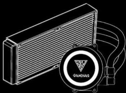
Technical line drawing of a heat exchanger with a circular component labeled 'GAMDIAS' (no other text or symbols)X1
H

IJKL


X1X4 X8 X4 X4
M

natural_image
Technical line drawing of a mechanical component (no text or symbols)N

natural_image
Abstract white line drawing on black background with no text or symbols0

natural_image
Simple line drawing of a tool or tool handle (no text or symbols)X1 X2
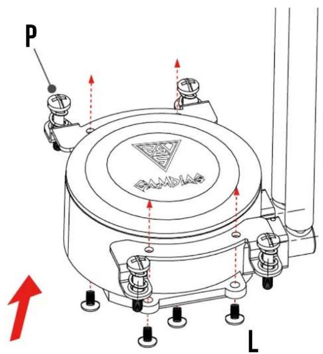
P

natural_image
Technical line drawing of a mechanical bracket with two cylindrical components and mounting holes (no text or symbols)
natural_image
Technical line drawing of a mechanical bracket with mounting holes and a labeled section 'X2' (no text or symbols on the diagram itself)R

natural_image
Pure geometric shape resembling a curved bracket with two circular holes, labeled 'X2' at bottom (no text or symbols within the shape)S

natural_image
Technical line drawing of a mechanical component with four symmetrical arms and central slot (no text or symbols)T
X1

natural_image
Line drawing of a mechanical bolt or screw assembly (no text or symbols)X4
U

V
X4

natural_image
Pure mechanical bracket diagram without any text, numbers, or symbolsX1
W
natural_image
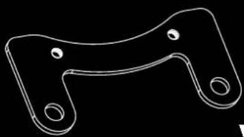
Pure technical line drawing of a mechanical bracket (no text or symbols)X1
Pump Dimensions


1
2

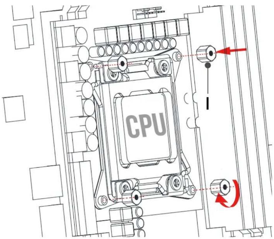
INTEL (LGA1366/115X/1200)
3
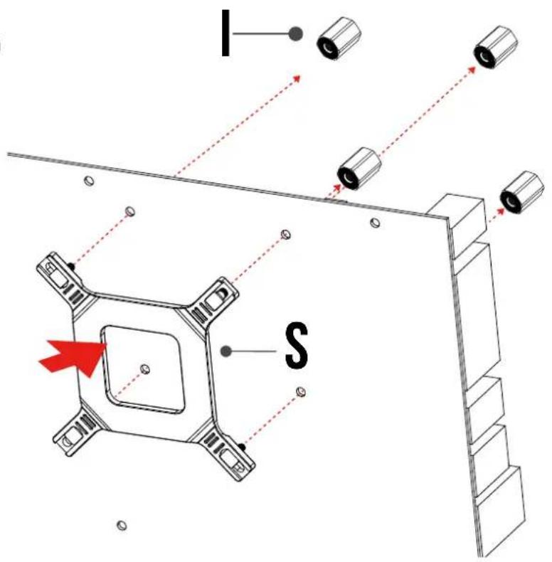


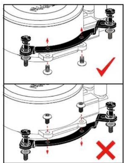
The insulating plate should face with motherboard
4

5
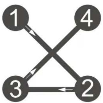
flowchart
graph TD
    1 --> 3
    1 --> 2
    2 --> 3
    2 --> 4
    3 --> 1
    3 --> 2
    4 --> 1

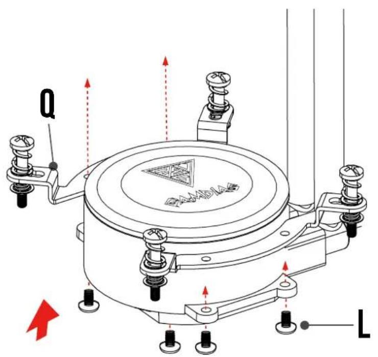
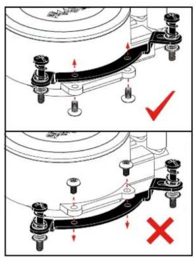
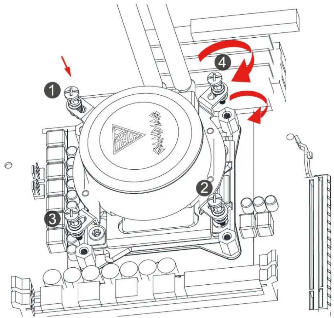
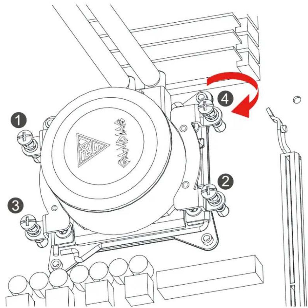
Please tighten the screws in a diagonal sequence to spread the tension properly.

natural_image
Mechanical assembly diagram showing a spring-loaded component with red bidirectional arrows indicating movement or force (no text or symbols)1
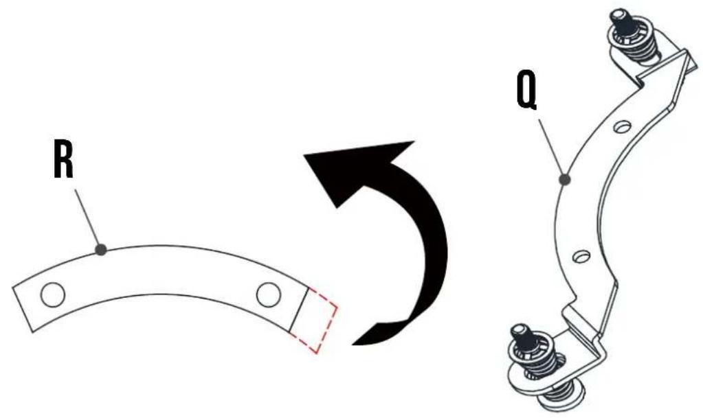
2

3

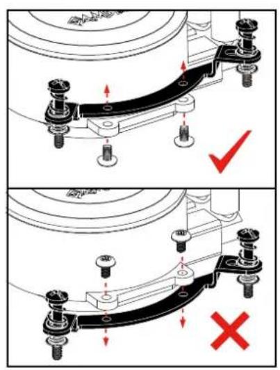
4

INTEL [ LGA1700 ]
5


![Gamdias Chione M2-240R - INTEL [ LGA1700 ] - 3](/content/2026/05/1044151/images/3eddc7ea7840ad35874d3ca96d3a0a7f132d330f671a8fd9bbee66f1f2aebe5d.jpg)
The insulating plate should face with motherboard
6


INTEL [ LGA1700 ]
7

![Gamdias Chione M2-240R - INTEL [ LGA1700 ] - 2](/content/2026/05/1044151/images/a1c092fa0cf5da7a2a37333ebe37a2ff76ccc67e6e5adb460e456ccb5d4f3406.jpg)
flowchart
graph TD
    1 --> 2
    2 --> 3
    3 --> 1
    3 --> 4
    4 --> 1
![Gamdias Chione M2-240R - INTEL [ LGA1700 ] - 3](/content/2026/05/1044151/images/95ebb1c89ed1006957af5a7b7ecc4f83ec1b7bb4c1409d150541631469aea735.jpg)
Please tighten the screws in a diagonal sequence to spread the tension properly.
![Gamdias Chione M2-240R - INTEL [ LGA1700 ] - 4](/content/2026/05/1044151/images/c2e0514c28a6ec880fa0bcd426db29159c4e7c6a2e7e90f75c71c5cded505e89.jpg)
natural_image
Mechanical assembly diagram showing a spring-loaded component with red bidirectional arrows indicating movement (no text or symbols)1
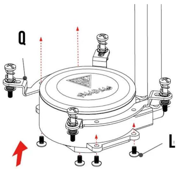
2


INTEL [ LGA2066/2011/2011-3 ]
3

![Gamdias Chione M2-240R - INTEL [ LGA2066/2011/2011-3 ] - 2](/content/2026/05/1044151/images/1f1173bbfc54384d8eaf7f71ec6a4323a2f2a10e9544f0585775fa56cf6ab000.jpg)
flowchart
graph TD
    1 --> 3
    1 --> 2
    2 --> 3
    2 --> 4
    3 --> 1
    4 --> 1
![Gamdias Chione M2-240R - INTEL [ LGA2066/2011/2011-3 ] - 3](/content/2026/05/1044151/images/3b88e3b64be9de09cb003265254fb841521ba201ec68e610ce93cc27b2fbf248.jpg)
Please tighten the screws in a diagonal sequence to spread the tension properly.
![Gamdias Chione M2-240R - INTEL [ LGA2066/2011/2011-3 ] - 4](/content/2026/05/1044151/images/1d46bee10e1c99340241f168604563aefa9753983650b9ac4e94aadad66a1142.jpg)
natural_image
Mechanical assembly diagram showing a spring-loaded component with red bidirectional arrows indicating movement or force (no text or symbols)AMD(AM4/AM3+/AM3/AM2+/AM2/FM2+/FM2/FM1)
1

2

AMD(AM4/AM3+/AM3/AM2+/AM2/FM2+/FM2/FM1)
3

flowchart
graph TD
    1 --> 2
    2 --> 3
    3 --> 1
    3 --> 2
    4 --> 1
    4 --> 2

Please tighten the screws in a diagonal sequence to spread the tension properly.
natural_image
Mechanical assembly diagram showing a spring-loaded component with red bidirectional arrows indicating movement or force (no text or symbols)AMD(CTR4)
1


2


flowchart
graph TD
    1 --> 2
    2 --> 3
    3 --> 1
    3 --> 4
    4 --> 1

Please tighten the screws in a diagonal sequence to spread the tension properly.
1 Turn off the computer before installing

2

3
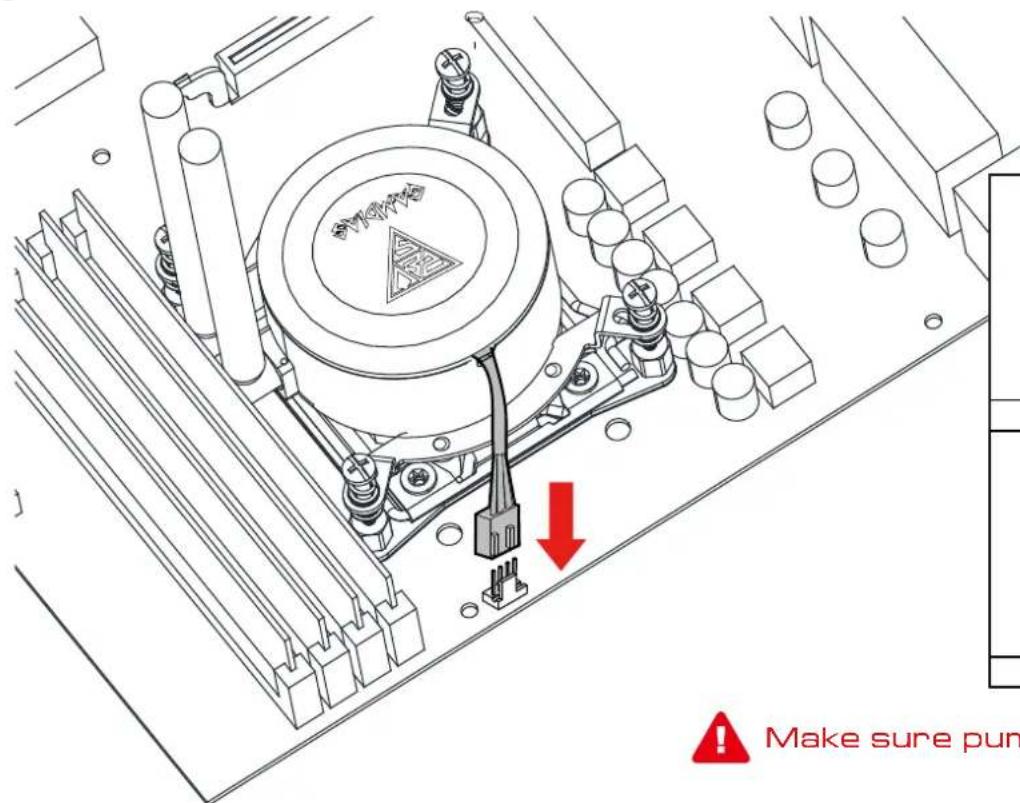


Make sure pump firmly touch CPU
4

5

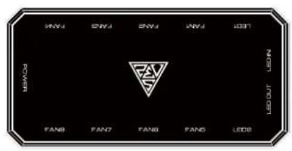
AEDLUS Box attaches to the computer case via magnet
6
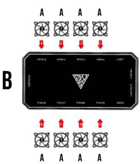
flowchart
graph TD
    A["A"] -->|4| B["LEDOUT LED"]
    C["A"] -->|3| B
    D["A"] -->|2| B
    E["A"] -->|1| B
    F["LEDOUT LED"] --> G["FAN8"]
    F --> H["FAN7"]
    F --> I["FAN6"]
    F --> J["FAN5"]
    F --> K["LEDE"]
    L["A"] --> M["A"]
    N["A"] --> O["A"]
    P["A"] --> Q["A"]


! Foolproof design
English
◆ Fans must start at "1" and continue in series. FAN1 → FAN2 → FAN3 → FAN4 → FAN5 → FAN6 → FAN7 → FAN8
◆ Any fan not connected in series will break communication and the RGB lighting fuction will not work.
Español
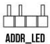
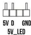
If your motherboard has 5V 3-Pin addressable (digital) RGB header, you can customize RGB lighting via motherboard manufacture sync software


F








natural_image
Close-up of a circuit board with visible LED and resistor components (no readable text or symbols)
natural_image
Close-up of a circuit board with three white 12V power connectors and a red X symbol (no readable text or symbols)

CHIONE M2-240R only support 5V addressable (digital) RGB header

Daisy chain another AEOLUS Box for more lighting effects
B
E

B


B
E
LED-Z

B
E

Notice foolproof design
10
B

D


B
POWER

D


D
11
Turn on the computer after installing
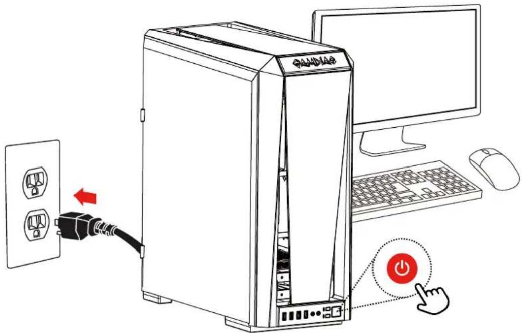
12
How to change the Battery
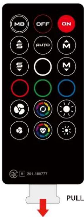



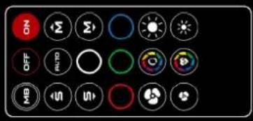
* When press "OFF" button, the remote controller will be automatically disabled.
Please press "ON" button to activate.
* Press "MB" button to switch to motherboard sync mode.

natural_image
Abstract geometric logo with interlocking black and gold shapes inside a large triangle (no text or symbols)GAMDIAS
GRMING ART IN MOTION
Brand : Gamdias
Model : Chione M2-240R
Category : Computer Cooling Component