
IPOE-175S - Signal separator Planet - Free user manual and instructions
Find the device manual for free IPOE-175S Planet in PDF.


| Product Type | Industrial IP67 802.3bt PoE++ Splitter |
| Model | IPOE-175S |
| Input Interface | 1 x 10/100/1000BASE-T Ethernet with IEEE 802.3bt PoE++ (PoE + Data) RJ45 |
| Output Data Port | 1 x 10/100/1000BASE-T Data out RJ45 |
| Output Power | 1 x 2-pin terminal block DC out, 12V DC, 6A (70W max) |
| PoE Standard | IEEE 802.3bt PoE++ Type 3, backward compatible with IEEE 802.3at/af |
| Input Voltage | 44~58V DC (for 802.3bt PoE++) |
| Power Pin Assignment | 1/2(-), 3/6(-), 4/5(+), 7/8(+) |
| LED Indicators | PWR (Green), DC Ready (Green) |
| Dimensions (W x D x H) | 150 x 43.8 x 72.94 mm (with cable gland: 159.85 x 42.9 x 72.94 mm) |
| Weight | 424 g |
| Enclosure Rating | IP67, IK10 aluminum case |
| Operating Temperature | -40°C to 75°C |
| Storage Temperature | -40°C to 95°C |
| Humidity | 5% to 95% (non-condensing) |
| ESD Protection | Air 8kV DC, Contact 6kV DC |
| Surge Protection | 5 kV |
| MTBF | >100,000 hrs |
| Regulatory Compliance | FCC Part 15 Class A, CE |
| Installation | Wall-mount, cable gland included for waterproof connections |
Frequently Asked Questions - IPOE-175S Planet
User questions about IPOE-175S Planet
0 question about this device. Answer the ones you know or ask your own.
Ask a new question about this device
Download the instructions for your Signal separator in PDF format for free! Find your manual IPOE-175S - Planet and take your electronic device back in hand. On this page are published all the documents necessary for the use of your device. IPOE-175S by Planet.
USER MANUAL IPOE-175S Planet
Thank you for purchasing PLANET Industrial IP67 802.3bt PoE++ Splitter, IPOE-175S. In the following sections, the term "Outdoor PoE Splitter" means the IPOE-175S.
Open the box of the IPOE-175S and carefully unpack it. The box should contain the following items:
| IPOE-175S x 1 User's Manual x 1 | M22 Waterproof Cable Gland x 3 | |
| Power Cable with 2-pin Terminal Block x 1 | Wall-mounted Kit x 1 Ground Wire x 1 | |
If any of these are missing or damaged, please contact your dealer immediately; if possible, retain the carton including the original packing material, and use them again to repack the product in case there is a need to return it to us for repair.
-1--3--5--7-
2. Hardware Introduction
This section describes the functionalities of the Outdoor PoE Splitter's components.
2.1 Product Outlook
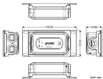
Figure 2-1: IPOE-175S product outlook
2.2 Power Input Port
Figure 2-2 shows the Power Output port side of the IPOE-175S

Figure 2-2: Power Output Port
2.3 802.3bt PoE++ Input Port and Data Output Port
Figure 2-3 shows the Date + PoE++ Input Port and Data Output Port side of the IPOE-175S.

Figure 2-3: Two RJ45 Ports
2.4 LED Indicators
| LED Color Function | |
| PWR Green | Indicates it has power. |
| DC Ready Green | Indicates the port is providing 12V DC in-line power. |
| To install the 2-pin Terminal Block Connector on the Outdoor PoE Splitter, simply follow the following steps:Step 1: Insert positive DC power wire into V+, negative DC power wire into V-, and grounding wire into Ground. | |
Step 2: Tighten the wire-clamp screws for preventing the wires from loosening and plug them into the Outdoor PoE Splitter
| Note | 1. The wire gauge should be in the range from 20 to 22 AWG.2. The device must be grounded. |
-2--4--6--8-
3. Installation
This section describes how to install the Outdoor PoE Splitter and make connections to it. Please read the following topics and perform the procedure in the order being presented.
3.1 Installing Cable Gland with Power Cable and RJ45 UTP Cable
The cable gland consists of the following:
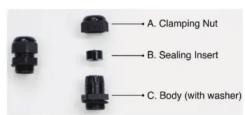
3.2 Connecting Waterproof Cable Kit to the Outdoor PoE Splitter
Step 1: Turn clockwise to tighten the gland body connected to the Outdoor PoE Splitter.
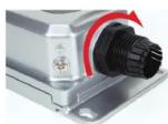
Step 2: Plug the power cable connector into the power output port.

Step 3: Insert the sealing insert into the cable gland body.
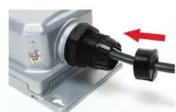
Step 4: Attach the clamping nut to the cable gland to complete the cable assembly.


Make sure the clamping nut is tightly attached to the cable gland body and the sealing insert is squeezed tightly.

Step 5: Repeat Steps 1 to 4 for "Data" output Port and "PoE (Data + Power)" input Port.
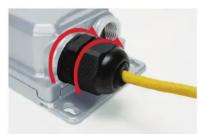


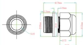
- Never use any waterproof cable gland that is not purchased from PLANET or doesn't have the same dimensions of the IPOE-175S; it will damage the device permanently.
3.3 Wall-mount Installation
To install the Outdoor PoE Splitter on the wall, please follow the instructions described below.
Step 1: Find the wall that you want to mount the Outdoor PoE Splitter on.
Step 2: Refer to the picture below to screw the four screws on the wall.
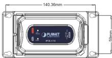
Step 3: Use a screwdriver to screw them into the wall.

3.4 Grounding the Device
Users MUST complete grounding wired with the device; otherwise, a sudden lightning could cause fatal damage to the device.

-9--11-
- Product Specifications
| Product IPOE-175S | ||
| Hardware Specifications | ||
| Interface | Input Port | 1 x 10/100/1000BASE-T Ethernet with IEEE 802.3bt PoE++ "PoE + Data" in RJ45 port |
| Output Port | 1 x 10/100/1000BASE-T "Data" out RJ45 port | |
| Output Power Terminal Block | 1 x 2-pin terminal block "DC" out port - Pin 1/2 for Power (Pin 1: V+ / Pin 2: V-) | |
| Data Rate 10/100/1000Mbps | ||
| LED Indicator | PWR (Green) DC Ready x 1 (Green) | |
| Input Voltage 44~56V DC | ||
| Power Requirement | 4-pair 802.3at PoE+ and 802.3bt PoE++: 52~56V DC 802.3at PoE+: 48~56V DC | |
| Power Consumption | Ethernet full loading without DC output: Full loading with maximum 12V DC, 5A output: 70watts | |
| ESD Protection | Air 8KV DC Contact 6KV DC | |
| Surge Protection 6KV | ||
| Enclosure IP67-rated and 1K10 aluminum case | ||
| Installation | Wall-mount ear | |

PLANET Networking & Communication

PLANET Networking & Communication
User's Manual
www.PLANET.com.tw
Industrial IP67 802.3bt PoE++ Splitter
IPOE-175S

PLANET Technology Corp.
10F, No. 96, Minquan Rd., Xindian Dist., New Taipei City 231, Taiwan
— Macc
This device is compliant with Class A of CISPR 32. In a residential environment this device may be on
in a residential environment this notice may cause fault inoverforce,
23S1-AH8110-000


EMD (Lightning) DAMAGE IS NOT CONVERED UNDER WARRANTY.
3.5 Connecting IPOE-175S to PSE
![graph TD A["802.36t PVE++ PSE"] -->|100m| B["IPOE-175S"] B --> C["DC12V"] C --> D["Non-PeL Device"] B --> E["10/100/100BASE+"] E --> F["Power Line (DC)"] B --> G["100BASE T UTF"] B --> H["100BASE T UTF with PoL"] B --> I["Power Line (DC)"]](/content/2026/05/1044036/images/c60cc0f4826f1ee3ab3b04d9658c292b0878172c9d67cdb9efe64ec48fe47f4e.jpg)
Step 1: Connect attached "Power cable with 2-pin terminal block" to the "DC Out" port of IPOE-175S Splitter.
Step 2: Connect the other end of DC power wires to remote device. Tighten the wire-clamp screws for preventing the wires from loosening.
Step 3: Connect the Cat5e/6 cable to "PoE In" port from an 802.3bt PoE++ switch/injector to the IPOE-175S Splitter.
Step 4: Connect the Cat5e/6 cable from "Data" port of the IPOE-175S to remote device.
Step 5: Power on the 802.3bt PoE++ switch/injector.
Step 6: Once the "DC Ready" LED indicator is steadily lit steadily, it shows it is providing 12V DC power.
| Dimensions (W x D x H) | 150 x 43.8 x 72.94 mm169.85 x 43.8 x 72.94 mm, with cable gland |
| Weight | 424g |
| MTBF | >100,000 hours |
| Network Cable | 10BASE-T: UTP category 3, 5 cable (≤100m)100BASE-TX: UTP category 5, 5e cable (≤100m)1000BASE-T: UTP category 5e, 6 cable (≤100m) |
| Power over Ethernet | |
| PoE Standard | IEEE 802.3bt PoE++ type 3 PDBackward compatible with IEEE 802.3at PoE+ |
| PoE Power Supply Type | 802.3bt PoE++/PoH (Power over HDBaseT)802.3at PoE+ End-span/Mid-span |
| PoE Power Output | DC 12V, 5A (60W, full load) |
| Power Pin Assignment | 1/2 (-); 3/6 (+), 4/5 (+), 7/8 (-) or 1/2 (+); 3/6 (-), 4/5 (+), 7/8 (-) |
| Standards Conformance | |
| Regulatory Compliance | FCC Part 15 Class A, CE |
| Stability Testing | IEC 60068-2-32 (Free fall)IEC 60068-2-27 (Shock)IEC 60068-2-6 (Vibration) |
| Standards Conformances | IEEE 802.3 10BASE-T EthernetIEEE 802.3u 100BASE-TX Fast EthernetIEEE 802.3ab 1000BASE-T Gigabit EthernetIEEE 802.3af Power over Ethernet IEEE 802.3at Power over Ethernet PlusIEEE 802.3bt Power over Ethernet PlusPlus |
| Environment | |
| Operating Temperature | -40 ~ 75 degrees C |
| Storage Temperature | -40 ~ 85 degrees C |
| Humidity | 5 ~ 95% (non-condensing) |

The PoE power output ability will depend on the distance.
5. Customer Support
Thank you for purchasing PLANET products. You can browse our online FAQ resource and user's manual on PLANET web site first to check if it could solve your issue. If you need more support information, please contact PLANET support team.
PLANET online FAQs:
https://www.planet.com.tw/en/support/faq
Support team mail address:
Copyright © PLANET Technology Corp. 2020.
Contents are subject to revision without prior notice.
PLANET is a registered trademark of PLANET Technology Corp.
All other trademarks belong to their respective owners.
-10--12--13--14-
- HARDWARE INTRODUCTION
- 2.1 PRODUCT OUTLOOK
- 2.2 POWER INPUT PORT
- 2.3 802.3BT POE++ INPUT PORT AND DATA OUTPUT PORT
- 2.4 LED INDICATORS
- INSTALLATION
- 3.1 INSTALLING CABLE GLAND WITH POWER CABLE AND RJ45 UTP CABLE
- 3.2 CONNECTING WATERPROOF CABLE KIT TO THE OUTDOOR POE SPLITTER
- 3.3 WALL-MOUNT INSTALLATION
- 3.4 GROUNDING THE DEVICE
- CUSTOMER SUPPORT
Brand : Planet
Model : IPOE-175S
Category : Signal separator