SB46-75 - Soundbar SONANCE - Free user manual and instructions
Find the device manual for free SB46-75 SONANCE in PDF.


| Product Type | Soundbar |
| Brand | Sonance |
| Model | SB46-75 |
| Dimensions (W x H x D) | 46 x 3.5 x 4.9 inches (1170 x 90 x 125 mm) |
| Weight | 13.2 lbs (6.0 kg) |
| Power Supply | 100-240V AC, 50/60Hz |
| Power Consumption | 150W (max) |
| Audio Channels | 2.1 |
| Total Output Power | 200W RMS |
| Frequency Response | 35Hz - 20kHz |
| Connectivity | Bluetooth 5.0, HDMI ARC, Optical, 3.5mm AUX, USB |
| Supported Audio Formats | Dolby Digital, DTS |
| Wall Mountable | Yes (brackets included) |
| Remote Control | Yes (IR) |
| Cleaning Instructions | Wipe with a soft, dry cloth. Do not use liquids. |
| Safety Precautions | Do not expose to rain or moisture. Operate in well-ventilated area. |
| Spare Parts Availability | Contact Sonance service center for spare parts. |
| Repair Information | Refer to user manual or authorized technician for service. |
Frequently Asked Questions - SB46-75 SONANCE
User questions about SB46-75 SONANCE
0 question about this device. Answer the ones you know or ask your own.
Ask a new question about this device
Download the instructions for your Soundbar in PDF format for free! Find your manual SB46-75 - SONANCE and take your electronic device back in hand. On this page are published all the documents necessary for the use of your device. SB46-75 by SONANCE.
USER MANUAL SB46-75 SONANCE
SB46-55 | SB46-65 | SB46-75 | SB46-85
ADJUSTABLE WIDTH MODELS
SB46 M | SB46 L
TABLE OF CONTENTS
2 Important Safety Instructions
3 Box Contents
4 Bracket Placement & Connectors
5 Display Spacers
6 Assembling & Connecting Attachment Rails
7 Adjusting Width & Wiring
8 Mounting & Calibrating
9 Dimensions
10 Warranty

Scan QR code for additional information and resources. For technical support call (949) 492-7777 or visit www.sonance.com/home-theater/soundbar
IMPORTANT SAFETY INSTRUCTIONS
This product is intended to be installed by professional AV integrators and installers only. This product manual is intended to serve as a general guideline for most applications. It is the installer's responsibility to ensure this product is installed in accordance with local building codes and regulations. Consult a local authority for specific requirements, regulations, and building codes of the jurisdiction in which this product is to be installed.
READ THIS DOCUMENT IN ITS ENTIRETY BEFORE ATTEMPTING USE
- Read these instructions.
- Keep these instructions.
- Heed all warnings.
- Follow all instructions.
- Clean only with a dry cloth.
- Do not block any ventilation openings. Install in accordance with the manufacturer's instructions.
- Do not install near a heat source such as radiators, heat registers, stoves, fireplaces, or other apparatus (including amplifiers) that produce heat.
- Only use attachments/accessories specified by Sonance.
- To be installed in indoor locations only.
- Refer all servicing to qualified service personnel.
INTRODUCTION
Thank you for purchasing the Sonance Soundbar. When properly installed, your new Soundbar will give you years of entertainment pleasure. The Sonance Soundbar is a high performance Left, Center, & Right 3-way speaker system housed in a sealed aircraft grade aluminum enclosure. Sonance Soundbar models are designed to meet the design and width of modern flat panel televisions. Your Soundbar is intended to match the following size television displays: SB46-55 for displays 55" diagonal; SB46-65 for displays 65" diagonal; SB46-75 for displays 75" diagonal; SB46-85 for displays 85" diagonal. Sonance Adjustable Width Soundbars are designed to slide wider or narrower to match medium or large TV displays as follows: SB46L for displays 70" to 80" diagonal; SB46M for displays 50" to 65" diagonal.
BOX CONTENTS
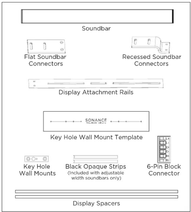
(1) Quickstart Guide
(1) Soundbar
(2) Flat Soundbar Connectors
(2) Display Attachment Rails
(2) Keyhole Wall Mounts
(1) Keyhole Wall Mount Template
(2) Recessed Soundbar Connectors
(2) Display Spacers
(1) 6-pin block connector
(2) Black Opaque Strips
(included with adjustable width soundbars only)
HARDWARE PACK
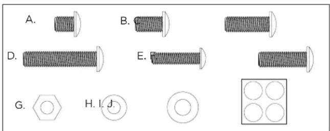
A. (4) M8 10mm Screws for Display Attachment Rails
B. (4) M8 14mm Screws for Flat Connector
C. (4) M8 23mm Screws for Recessed Connector
D. (4) M8 38mm Screws for Recessed Connector
E. (4) M6 25mm Screws
F. (4) M8 25mm Screws
G. (8) M8 Nuts
H. (8) M6 Washers
I. (8) M8 Washers
J. (4) Rubber Feet
WALL MOUNT INSTALLATIONS
SB46 M
24 lbs. For displays 50"-65" (1270mm to 1651mm)
SB46 L
29 lbs. For displays 70"-80" (1778mm to 2032mm)
SB46-55
28 lbs. For 55" displays
HxDxW: 5 9/32" (134mm) x 2 9/16" (65mm) x 48 5/16" (1227mm)
SB46-65
30 lbs. For 65" displays
HxDxW: 5 9/32" (134mm) x 2 9/16" (65mm) x 56 15/16" (1445mm)
SB46-75
33 lbs. For 75" displays
HxDxW: 5 9/32" (134mm) x 2 9/16" (65mm) x 66"
(1676mm)
SB46-85
35 lbs. For 85" displays
HxDxW: 5 9/32" (134mm) x 2 9/16" (65mm) x 75 1/4" (1911mm)
NOTE: VERIFY WALL MOUNT WILL SUPPORT COMBINED WEIGHT OF DISPLAY AND SOUNDBAR.
NOTE: CAREFULLY FOLLOW INSTALLATION DIRECTIONS FOR THE THIRD PARTY DISPLAY WALL MOUNT.
Before any installation carefully plan where wiring will pass through walls. Perform an obstruction survey using a stud finder to be certain there are no studs, conduit, pipes, heating ducts, pocket doors or air returns in the wall cavity. If you are unsure about obstructions, drill a small hole near where the Soundbar wire terminals will be located and insert a coat hanger wire into the hole to feel around for possible obstructions.
Run three sets of speaker wires: Left channel, Center channel, Right channel as well as the necessary video cable from the amplifier to the display location.
Whenever possible leave extra wire to make it easy to connect the wire to the provided quick clip, 6-pin block connector prior to hanging the display. Extra wire can then be pushed back into the wall.
NOTE: CONSULT LOCAL BUILDING CODES BEFORE RUNNING SPEAKER AND ELECTRICAL WIRES THROUGH WALLS.
PLACEMENT AND OPTIONS OVERVIEW
Sonance Soundbars are designed to attach directly to most flat panel display wall mounts using VESA mounting points with the included attachment rails, connectors, and hardware.
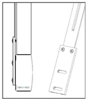
FLAT MOUNT INSTALLATION OPTION 1
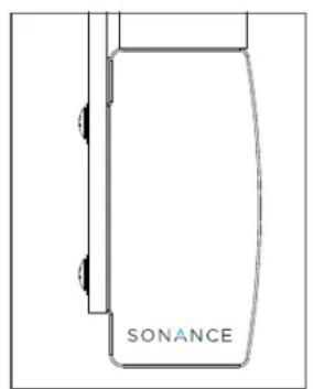
The flat soundbar connector will align with displays 25/8" (65mm) deep.
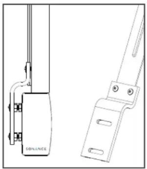
RECESSED MOUNT INSTALLATION OPTION 2
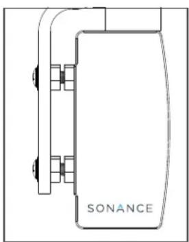
The recessed soundbar connector will align with displays from 17/32" - 23/32" (31.74mm - 53mm) deep.
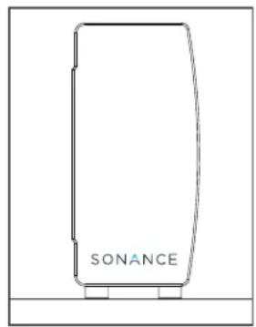
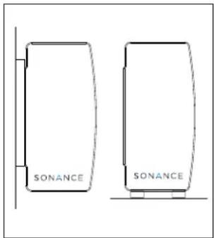
TABLE TOP INSTALLATION OPTION 3
Soundbars can additionally be cabinet or table top mounted using the rubber feet included in your box contents.
KEYHOLE WALL MOUNT INSTALLATION OPTION 4
Using the key hole wall mounts combined with the wall mount template.
natural_image
Simple line drawing of a door with a label 'SONANCE' on the side (no other text or symbols)Option 1:
Flat Soundbar Connector
natural_image
Technical line drawing of a device with labeled 'SONANCE' (no other text or symbols)Option 2:
Recessed Soundbar Connector
natural_image
Simple line drawing of a rectangular device with 'SONANCE' text on the side (no other text or symbols)Option 3:
Table Top Installation
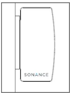
Option 4:
Key Hole Wall Mount
SOUNDBAR CONNECTORS FOR WALL MOUNT BRACKETS
Choose and attach the correct soundbar connector to the display attachment rails for your desired depth. The flat soundbar connector will align with 2 5/8" (65mm) deep displays. The recessed soundbar connector will align with displays from 1 7/32" - 2 3/32" (31.74 - 53mm) deep.
natural_image
Technical line drawing of a door handle and support bracket (no text or symbols)Option 1:
Flat Soundbar Connector
natural_image
Technical line drawing of a mechanical component with labeled parts (no readable text or symbols)Option 2:
Recessed Soundbar Connector
ATTACHING THE SOUNDBAR CONNECTOR
NOTE: FOR INSTALLATION OPTIONS 3 AND 4, BEGIN ON PAGE 6.
OPTION 1 - FLAT SOUNDBAR CONNECTOR
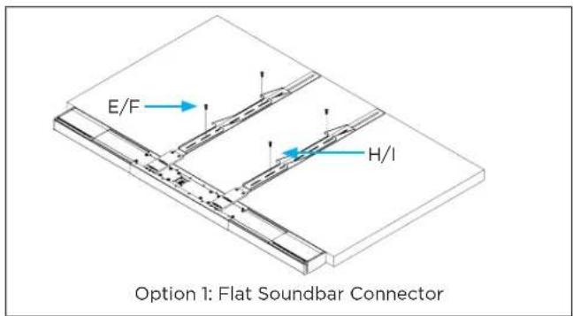
The flat soundbar connector will align with 2 5/8" (65mm) displays. Use the A. screws to connect to the display attachment rails.
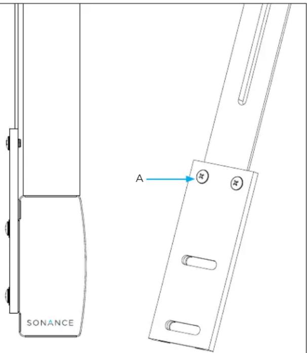
Option 1: Flat Soundbar Connector
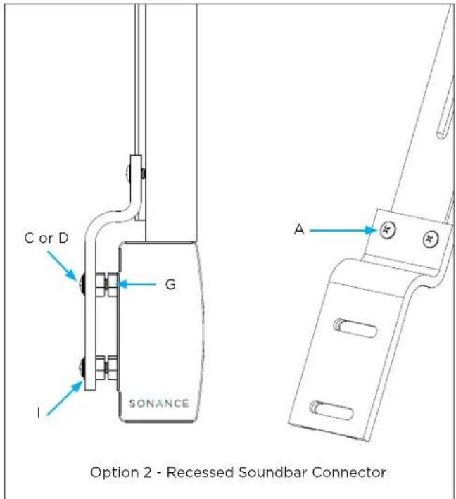
OPTION 2 - RECESSED SOUNDBAR CONNECTOR
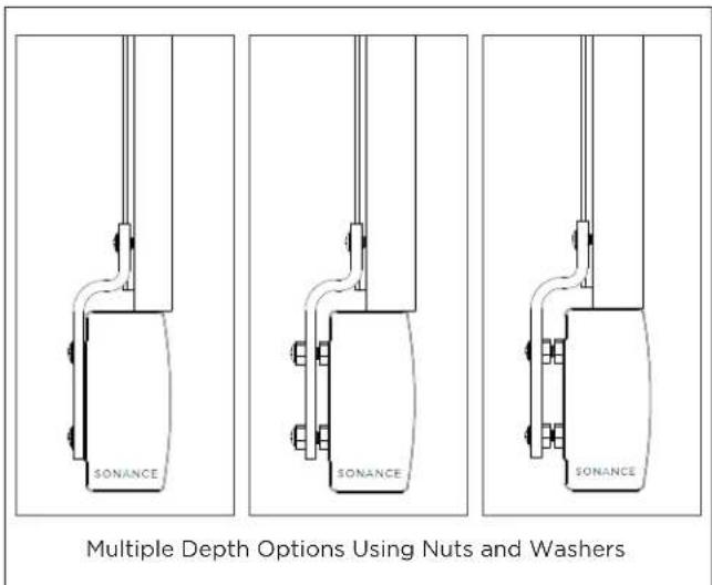
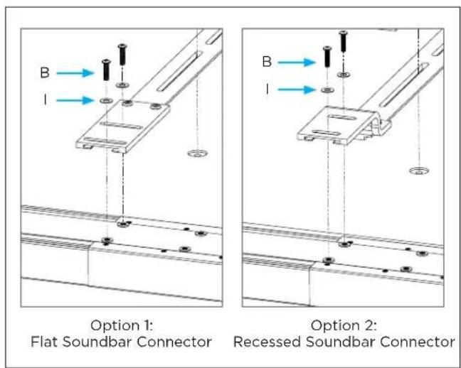
The recessed soundbar connector will align with displays from 1 7/32" (31.74mm) to 2 3/32" (53mm) deep displays. Various depths can be accomplished by using C. or D. screws accompanied by I. washers and G. nuts. Use the A. screws to attached the connector to the display attachment rails.
DISPLAY SPACERS
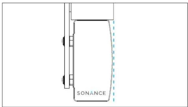
Included with your soundbar are two 8mm thick wood display spacers. The spacers allow the front surface of the display to be in line with the flat surface on the top edge of the soundbar. When using the spacers carefully place the display on top of the spacers. This will require two people. Be careful not to scratch the display. spacers do not go under the soundbar.
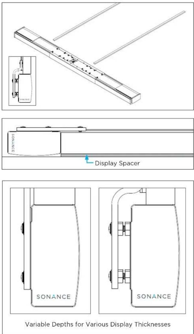
NOTE: IF THE SPACERS ARE NOT USED, THE FRONT SURFACE OF THE DISPLAY WILL BE IN LINE WITH THE FRONT RADIUS OF THE SOUNDBAR GRILLE. THIS IS DEPENDENT ON THE DISPLAY THICKNESS AND INSTALLATION PREFERENCE.
ASSEMBLING AND CONNECTING THE ATTACHMENT RAILS
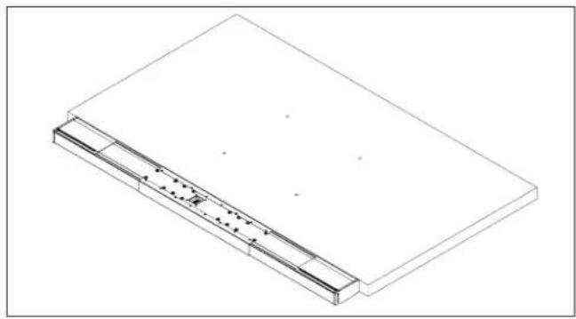
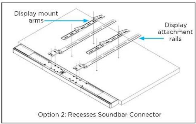
Carefully place the display face down on a soft flat surface. This will require two people. Place the soundbar face down and position it as close to the display as possible.
natural_image
Isometric line drawing of a rectangular panel with internal structure and mounting holes (no text or symbols)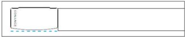
Position the soundbar display attachment rails on the back of the display mounting points. Place the display mount arms on top of the display attachment rails. The bottom end of the display attachment rails should be flush with the bottom of your display. Make sure that the screw inserts on the display and attachment rails are aligned.
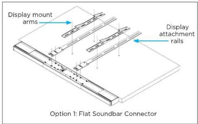
Position the soundbar as close to display as possible. Firmly fasten B. screws with I. washers to connect soundbar to the soundbar connectors.
Secure the wall bracket and attachment rails to the display using spacers and screws supplied with the wall mount or E. and F. screws with H. and I. washers (depending on the size of the display's threaded Inserts. E. and H. are M6; F. and I. are M8). Hardware will vary. It is recommended to keep spacers and hardware provided with display or display mount. Refer to your display manual for the proper torque to be applied to the screws.
ADJUSTING GRILLE WIDTH
NOTE: FOR ADJUSTABLE WIDTH SOUNDBAR MODELS ONLY: SB46 L |SB46 M
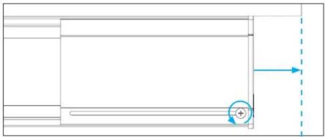
Be sure to complete this step prior to attaching the display and soundbar to wall mount bracket. Adjust the side grilles of the soundbar to achieve perfect symmetry with the display. Loosen the rear lock screw on each side grille and slide the grille out to match the width of the display. No tool required. Once the width is set tighten the lock screws finger tight.
natural_image
Pure technical diagram showing a rectangular component with a circular feature and directional arrows, no text or symbols present.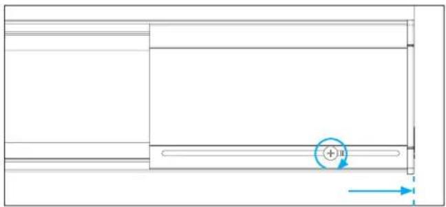
natural_image
Pure technical diagram showing a rectangular panel with horizontal lines and a circular indicator labeled '+n' (no text or symbols beyond the indicator)ADJUSTING WIDTH MODELS ONLY
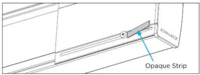
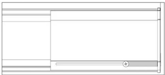
Included with your soundbar is a pair of black textured opaque strips (included with Adjustable Width soundbar models only: SB46 L and SB46 M). These are used to cover the remaining open area where the lock screw slides through. In some conditions light may pass through this area into the grille. Peel off the adhesive backing and place the strip over the open area and cut to size. The radius side fits against the lock screw.
natural_image
Pure technical line drawing of a rectangular frame with horizontal and vertical lines, no text or symbols presentWIRING THE SOUNDBAR (ALL MODELS)
We suggest leaving extra wire length to make it easy to connect the wire to the provided quick clip, 6-pin block connector prior to mounting the display. The extra wire can then be pushed back into the wall.
- Strip approximately 0.1875" (5mm) of the insulation from each wire.
NOTE: STRAY STRANDS THAT TOUCH EACH OTHER CAN CAUSE A SHORT-CIRCUIT THAT CAN DAMAGE THE AMPLIFIER.
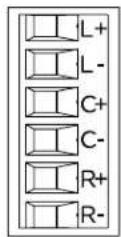
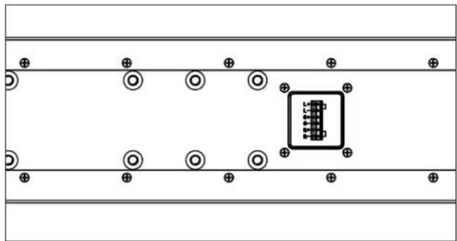
- The Sonance soundbar is designed for simple wiring using a provided 6-pin block connector. Insert the wire into the correct square opening on the connector. Use a small flat head screwdriver to tighten the corresponding screw to secure the wire. From top to bottom, as labeled, the wires should be ordered: Left positive (L+), Left negative (L-), Center positive (C+), Center negative (C-), Right positive (R+), and Right negative (R-). Once all wires are secure, snap the 6-pin block connector into position into the back of the Sonance soundbar, matching the pin connections to their appropriate placement.
natural_image
Pure electrical circuit lines without any symbolsSTEREO WIRING
If you are using a 2 channel amp or stereo receiver only hook up the left and right channels of soundbar. Connect AC power and video cable to display.
OPTION 3 - KEY HOLE WALL MOUNT
Sonance Soundbars can be mounted directly to the wall surface. Choose the soundbar location and identify the studs in the wall with a stud finder. Use a level and the supplied cardboard key hole wall mount template to mark the locations on the wall where the screws should be located. Temporarily tape the template to the wall once it is level and mark the holes with a pencil. Make sure the template is perfectly aligned with the display location then pre drill the pilot-hole locations. The 400mm mounting points correspond to the spacing of 16" on center studs.
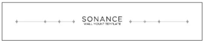
Place soundbar face down on a soft surface. Attach the two supplied key hole wall mounts to the back of the soundbar using the supplied A. screws. You can use any of the mounting points on the back of the soundbar.
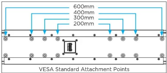
To hang key hole wall mount use only #10 - #12 pan head or flat head screws (not supplied). The screws must be firmly attached to the studs to support the weight of the soundbar. Align the screw heads into the large round portion of the key hole and gently slide into place.
NOTE: PUTTING SCREWS DIRECTLY INTO THE DRYWALL WILL NOT SUPPORT THE WEIGHT OF THE SOUNDBAR.
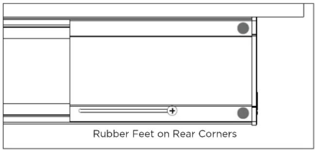
If attaching directly to drywall, we recommend self drilling drywall anchors that can easily accommodate the weight of the soundbars. Also highly recommended are the Togger® high-performance heavy duty toggle bolts. Rubber feet can be added to the left and right rear top and bottom edges of the soundbar to rest against the wall.
OPTION 4 - CABINET OR TABLE TOP INSTALLATION
Sonance Soundbars can be mounted in a cabinet or placed on a table top using the included four rubber feet. Remove the adhesive backing and place the rubber feet on the outer corners on the bottom of the soundbar. When using the soundbar in a cabinet make sure the soundbar is placed forward near the cabinet front edge, not in the rear of the cabinet. This will ensure best audio quality.
MOUNTING THE DISPLAY
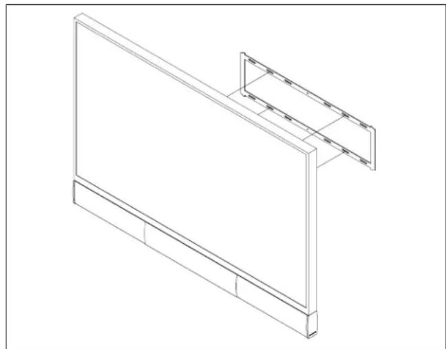
Carefully mount the display and soundbar to the third party TV wall mount. This will require two people. When lifting be careful not to place too much pressure on, or twist, the soundbar. This could bend the attachment rails.
natural_image
Isometric line drawing of a two-panel wall-mounted device with mounting brackets (no text or symbols)NOTE: WHEN LIFTING THE DISPLAY AND SOUNDBAR TOGETHER BE CAREFUL NOT TO PUT TOO MUCH PRESSURE ON THE SOUNDBAR ALONE.
CALIBRATING THE SOUNDBAR
Soundbar installation is now complete and ready for audio system calibration. Using a subwoofer is recommended. The subwoofer crossover frequency should be set to 100Hz. We recommend the Sonance VPSUB with a Sonance DSP 2-150 MKII amplifier or a Sonance Impact cabinet subwoofer. The Sonance VP46R SST/SUR, VP66R SST/SUR, and VP86 SST/SUR are perfect surround speakers to pair with the soundbar.
Use test tones in the surround processor to verify Left/ Center/Right channels have been properly connected and to set levels.
Your soundbar will sound great out of the box, however, as with any high performance loudspeaker, a 40 hour play period will “break in” the drivers and enhance the overall listening experience. This only needs to be done once.
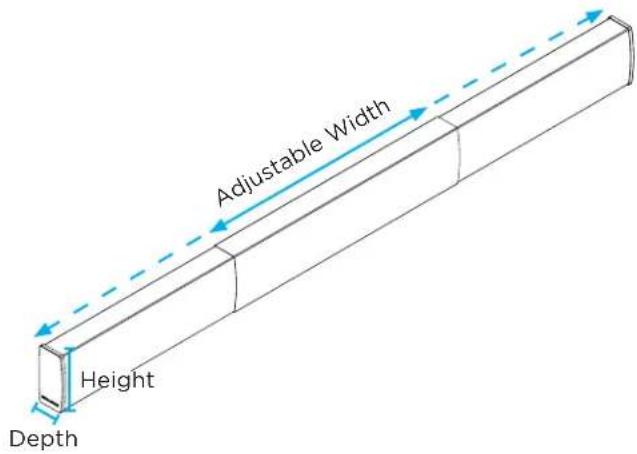
ADJUSTABLE WIDTH SOUNDBARS DIMENSIONS
Model SB46 M
Height 5 9/32" (134mm)
Depth 2 9/16" (65mm)
Adjustable Width 43 7/8" to 59 5/8" (1114mm to 1514mm)
Display Size Range 50" to 65" diagonal (127cm to 165cm)
Model SB46 L
Height 5 9/32" (134mm)
Depth 29/16" (65mm)
Adjustable Width 61 1/2" to 77 5/16" (1562mm to 1964mm)
Display Size Range 70" to 80" diagonal (178cm to 203cm)
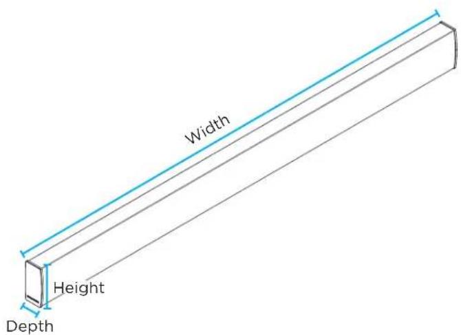
SOUNDBAR DIMENSIONS
| Model | SB46-55 | ||
| Height | 5 9/32" (134mm) | ||
| Depth | 2 9/16" (65mm) | ||
| Width | 48" | (1219.2mm) | |
| Model | SB46-65 | ||
| Height | 5 9/32" (134mm) | ||
| Depth | 2 9/16" (65mm) | ||
| Width | 56.25" | (1428.8mm) | |
| Model | SB46-75 | ||
| Height | 5 9/32" (134mm) | ||
| Depth | 2 9/16" (65mm) | ||
| Width | 65" | (1651mm) | |
| Model | SB46-85 | ||
| Height | 5 9/32" (134mm) | ||
| Depth | 2 9/16" (65mm) | ||
| Width | 73.75" | (1873.3mm) |
LIMITED ONE (1) YEAR WARRANTY
Sonance warrants to the first end-user purchaser that this Sonance-brand product (“Product”), when purchased from an authorized Sonance Dealer/Distributor, will be free from defective workmanship and materials for the period stated below. Sonance will at its option and expense during the warranty period, either repair the defect or replace the Product with a new or re-manufactured Product or a reasonable equivalent.
EXCLUSIONS
TO THE EXTENT PERMITTED BY LAW, THE WARRANTY SET FORTH ABOVE IS IN LIEU OF, AND EXCLUSIVE OF, ALL OTHER WARRANTIES, EXPRESS OR IMPLIED, AND IS THE SOLE AND EXCLUSIVE WARRANTY PROVIDED BY SONANCE. ALL OTHER EXPRESS AND IMPLIED WARRANTIES, INCLUDING THE IMPLIED WARRANTIES OF MERCHANTABILITY, IMPLIED WARRANTY OF FITNESS FOR USE, AND IMPLIED WARRANTY OF FITNESS FOR A PARTICULAR PURPOSE ARE SPECIFICALLY EXCLUDED.
No one is authorized to make or modify any warranties on behalf of Sonance. The warranty stated above is the sole and exclusive remedy, and Sonance's performance shall constitute full and final satisfaction of all obligations, liabilities, and claims with respect to the Product.
IN ANY EVENT, SONANCE SHALL NOT BE LIABLE FOR CONSEQUENTIAL, INCIDENTAL, ECONOMIC, PROPERTY, BODILY INJURY, OR PERSONAL INJURY DAMAGES ARISING FROM THE PRODUCT, ANY BREACH OF THIS WARRANTY, OR OTHERWISE.
This warranty statement gives you specific legal rights, and you may have other rights which vary from state to state. Some states do not allow the exclusion of implied warranties or limitations of remedies, so the above exclusions and limitations may not apply. If your state does not allow disclaimer of implied warranties, the duration of such implied warranties is limited to period of Sonance's express warranty. Your Product Model and Description: Sonance SB46 L | SB46 M | SB46-55 | SB46-65 | SB46-75 | SB46-85 Soundbars. Warranty Period for this Product: One (1) years from the date on the original sales receipt or invoice or other satisfactory proof of purchase. Additional Limitations and Exclusions from Warranty Coverage: The warranty described above is nontransferable, applies only to the initial installation of the Product, does not include installation of any repaired or replaced Product, does not include damage to allied or associated equipment which may result for any reason from use with this Product, and does not include labor or parts caused by accident, disaster, negligence, improper installation, misuse (e.g. overdriving the amplifier or speaker, excessive heat, cold or humidity, mishandling, etc.), or from service or repair which has not been authorized by Sonance. Obtaining Authorized Service: To qualify for the warranty, you must contact your authorized Sonance Dealer/Installer or call Sonance Customer Service at (949) 492-7777 within the warranty period, must obtain a return merchandise number (RMA), and must deliver the Product to Sonance shipping prepaid during the warranty period, together with the original sales receipt, or invoice or other satisfactory proof of purchase.
SONANCE
©2022 Sonance. All rights reserved. Sonance is a registered trademarks of Dana Innovations. Due to continuous product improvement, all features and specifications are subject to change without notice. For the latest Sonance product specification information visit our website: www.sonance.com
SONANCE • 991 Calle Amanecer • San Clemente, CA 92673 USA
PHONE: (949) 492-7777 • FAX: (949) 361-5151 • Technical Support: (949) 492-7777 • www.sonance.com
336-0063 v2.21
- ADJUSTABLE WIDTH MODELS
- TABLE OF CONTENTS
- IMPORTANT SAFETY INSTRUCTIONS
- READ THIS DOCUMENT IN ITS ENTIRETY BEFORE ATTEMPTING USE
- INTRODUCTION
- BOX CONTENTS
- HARDWARE PACK
- WALL MOUNT INSTALLATIONS
- SB46 M
- SB46 L
- SB46-55
- SB46-65
- SB46-75
- SB46-85
- NOTE: VERIFY WALL MOUNT WILL SUPPORT COMBINED WEIGHT OF DISPLAY AND SOUNDBAR.
- NOTE: CAREFULLY FOLLOW INSTALLATION DIRECTIONS FOR THE THIRD PARTY DISPLAY WALL MOUNT.
- NOTE: CONSULT LOCAL BUILDING CODES BEFORE RUNNING SPEAKER AND ELECTRICAL WIRES THROUGH WALLS.
- PLACEMENT AND OPTIONS OVERVIEW
- FLAT MOUNT INSTALLATION OPTION 1
- RECESSED MOUNT INSTALLATION OPTION 2
- TABLE TOP INSTALLATION OPTION 3
- KEYHOLE WALL MOUNT INSTALLATION OPTION 4
- SOUNDBAR CONNECTORS FOR WALL MOUNT BRACKETS
- ATTACHING THE SOUNDBAR CONNECTOR
- OPTION 1 - FLAT SOUNDBAR CONNECTOR
- OPTION 2 - RECESSED SOUNDBAR CONNECTOR
- DISPLAY SPACERS
- ASSEMBLING AND CONNECTING THE ATTACHMENT RAILS
- ADJUSTING GRILLE WIDTH
- NOTE: FOR ADJUSTABLE WIDTH SOUNDBAR MODELS ONLY: SB46 L |SB46 M
- ADJUSTING WIDTH MODELS ONLY
- WIRING THE SOUNDBAR (ALL MODELS)
- NOTE: STRAY STRANDS THAT TOUCH EACH OTHER CAN CAUSE A SHORT-CIRCUIT THAT CAN DAMAGE THE AMPLIFIER.
- STEREO WIRING
- OPTION 3 - KEY HOLE WALL MOUNT
- NOTE: PUTTING SCREWS DIRECTLY INTO THE DRYWALL WILL NOT SUPPORT THE WEIGHT OF THE SOUNDBAR.
- OPTION 4 - CABINET OR TABLE TOP INSTALLATION
- MOUNTING THE DISPLAY
- NOTE: WHEN LIFTING THE DISPLAY AND SOUNDBAR TOGETHER BE CAREFUL NOT TO PUT TOO MUCH PRESSURE ON THE SOUNDBAR ALONE.
- CALIBRATING THE SOUNDBAR
- ADJUSTABLE WIDTH SOUNDBARS DIMENSIONS
- SOUNDBAR DIMENSIONS
- LIMITED ONE (1) YEAR WARRANTY
- EXCLUSIONS
- SONANCE
Brand : SONANCE
Model : SB46-75
Category : Soundbar