DX-TX-4K60 - Extendeur AV AMX - Free user manual and instructions
Find the device manual for free DX-TX-4K60 AMX in PDF.


| Product Type | HDMI Extender (4K60) over HDBaseT |
| Brand | AMX |
| Model | DX-TX-4K60 |
| Video Resolution | Up to 4K @ 60Hz (4:4:4), 1080p @ 60Hz |
| Audio Support | HDMI audio pass-through, up to 7.1 channels PCM, Dolby TrueHD, DTS-HD |
| Transmission Distance | Up to 100 m (328 ft) over CAT6/6A/7 |
| Input Interface | 1x HDMI Type A female |
| Output Interface | 1x RJ45 (HDBaseT) female |
| Power Supply | 24V DC, 0.5A (included) or PoE (IEEE 802.3af) |
| Power Consumption | <10W |
| Dimensions (W x D x H) | 120 x 70 x 25 mm (approx.) |
| Weight | 200 g (approx.) |
| Operating Temperature | 0°C to 40°C |
| Storage Temperature | -20°C to 60°C |
| Humidity | 10% to 90% RH (non-condensing) |
| Features | EDID management, HDCP 2.2 compliant, IR pass-through (bidirectional), PoE support |
| Maintenance | Clean with dry cloth; avoid liquids. Do not use solvents. |
| Safety | Use only supplied power adapter. Do not expose to moisture or extreme temperatures. |
| Spare Parts | Power adapter, IR emitter/receiver (included), mounting brackets (optional) |
| Reparability | No user-serviceable parts. Contact AMX support for repairs. |
| Certifications | CE, FCC, RoHS |
| Included Accessories | Power adapter, IR emitter/receiver, mounting brackets, quick start guide |
Frequently Asked Questions - DX-TX-4K60 AMX
User questions about DX-TX-4K60 AMX
0 question about this device. Answer the ones you know or ask your own.
Ask a new question about this device
Download the instructions for your Extendeur AV in PDF format for free! Find your manual DX-TX-4K60 - AMX and take your electronic device back in hand. On this page are published all the documents necessary for the use of your device. DX-TX-4K60 by AMX.
USER MANUAL DX-TX-4K60 AMX
DIP Switch Toggles - Default OFF (for Auto-setup, see next page)
Before installing the units, find the scenario you are using in the table below and set the DIP switch toggles accordingly. Toggle #4 is reserved for future functionality.
For standalone pair upgrades, set Toggles #1-2-3 to ON and connect one unit to a Controller.
| COMMON SCENARIOS | TOGGLES |
| Standalone Setup | 1 - 2 - 3 |
| AV signals only (plus serial/IR passthrough) | OFF - OFF - OFF |
| AV with Ethernet passthrough to networked device (plus serial/IR passthrough)* | ON - OFF - OFF |
| AV with NetLinx control of TX/RX unit and serial/IR ports** | ON - ON - ON |
| AV with NetLinx control of TX/RX unit and serial/IR ports, plus Ethernet passthrough to network device* | ON - ON - ON |
| Switcher Setup (TX/RX with Enova DGX/DVX /DGX 100 Series Switcher) | 1 - 2 - 3 |
| AV signals only | OFF - OFF - OFF |
| AV with Ethernet passthrough to networked device* | ON - OFF - OFF |
| AV with NetLinx control of TX/RX unit and serial/IR ports | OFF - OFF - ON |
| AV with NetLinx control of TX/RX unit and serial/IR ports, plus Ethernet passthrough to network device* | ON - OFF - ON |
* Connect ICS LAN port of DXLink unit to network device (e.g., laptop, IP controlled projector, ICSLan Device). In standalone setup, connect ICS LAN port of other DXLink unit to network.
** In standalone setup using NetLinx control of DXLink serial/IR ports, only one of the DXLink units should be connected to network (the unit with #1 Toggle enabled).

FIG. 1 DIP SWITCH TOGGLES ENABLE/DISABLE SPECIAL FUNCTIONALITY
Overview
The DX-TX-4K60 and DX-RX-4K60 transmit HDMI, audio, USB and control over twisted pair cable. The TX also has an HDMI local loop out. DXLink Modules can be set up in one of three ways:
- Endpoint Mode (Switcher) – connect one or more to a switcher with an Integrated Controller.
- Endpoint Mode (Standalone) – connect TX/RX pair directly to each other with one connected to a NetLinx Central Controller via LAN or directly to Controller.
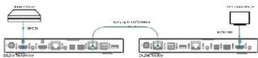
Extender Mode (Standalone) – connect TX/RX pair directly to each other.
These Modules support InstaGate Pro® and SmartScale® Technology.
The Hardware Reference Manual – DXLink Twisted Pair 4K60 Transmitters/Receiver contains complete documentation (including full specifications and supported input and output resolutions); for details, see www.amx.com.
System Setup
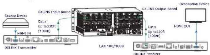
The DX-TX-4K60 and DX-RX-4K60 work with a switcher that supports DXLink Technology or as a stand-alone pair to transmit audio, video and control signals. The Transmitter receives audio and video from the HDMI source and transmits both audio and video over the DXLink twisted pair cable. This DXlink cable can be connected directly to a DXLink Receiver or to a DXLink input on a DXLink switcher where it can be routed to a DXLink output and connected to a DXLink Receiver. The DXLink Receiver converts the DXLink input to HDMI and analog audio outputs. On the Transmitter, stereo audio connections are provided as a supplemental audio input. Both the Transmitter and the Receiver support RS-232 for serial data transfer, USB, IR, and Ethernet.
flowchart
graph LR
    A["Source Device"] --> B["DXLINK Input Board"]
    B --> C["DXLINK Transmitter"]
    C --> D["LAN 100/1000"]
    D --> E["DXLINK Receiver"]
    E --> F["Destination Device"]
    G["Cat x Up to330F (100m)"] --> B
    H["Cat x Up to330F (100m)"] --> D
    I["HDMI OUT"] --> E
FIG. 2 DXLINK TX AND RX AS ENDPOINTS WITH COMPATIBLE DXLINK EQUIPMENT
flowchart
graph TD
    A["Router"] --> B["Server"]
    B --> C["Data port (BOSDA Server)"]
    C --> D["COSM Server"]
    D --> E["Server"]
    E --> F["Data port (COSM Server)"]
FIG. 3 DXLINK TX AND RX AS EXTENDER SOLUTION
Mounting Options (Rack Trays and Mounting Brackets)
For details on the four versatile mounting kit options for V Style modules (rack tray, rack tray with fill plates, surface mount, and pole mount), see www.amx.com
IMPORTANT: When mounting under a surface, the module should be mounted upright and lowered in the mounting bracket slots to provide an airflow gap between the surface and the vent holes. If not using V Style brackets, be sure to leave a gap between the top of the unit and the surface for heat to escape.
Twisted Pair Cable Pinouts and RJ-45 LEDs
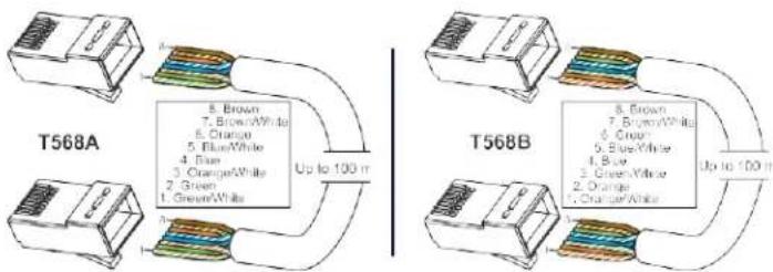
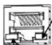
The DXLink and ICS LAN 10/100 ports both use twisted pair cable. FIG. 4 shows two pinouts that can be used for either port. FIG. 5 shows the LEDs for each port.
flowchart
graph TD
    subgraph T568A
        A["Green/White"] --> B["Brown/White"]
        B --> C["Orange/White"]
        C --> D["Blue/White"]
        D --> E["Brown/White"]
        E --> F["Orange/White"]
        F --> G["Brown/White"]
        G --> H["Blue/White"]
        H --> I["Brown/White"]
        I --> J["Orange/White"]
        J --> K["Brown/White"]
    end
    subgraph T568B
        L["Blue/White"] --> M["Brown/White"]
        M --> N["Orange/White"]
        N --> O["Brown/White"]
        O --> P["Orange/White"]
        P --> Q["Brown/White"]
        Q --> R["Blue/White"]
        R --> S["Brown/White"]
        S --> T["Orange/White"]
        T --> U["Brown/White"]
    end
    T568A -->|Up to 100 m| T568B
    T568B -->|Up to 100 m| T568A
FIG. 4 RJ-45 PINOUTS
Yellow LED
On - Speed status is 100 Mbps Off- Speed status is 10 Mbps
ICS LAN 10/100 Port
Green LED
On - Link status is active
Off- Link status is not active
FIG. 5 RJ-45 PORTS
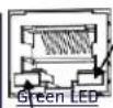
Yellow LED
On - Authenticated HDCP Flashing - Video active; no HDCP Off - No Video
DXLink Port
On - Connection established
Off- Connection not established
Attaching Signal, Transport, and Control Cables
Important Twisted Pair Cabling Requirements and Recommendations:
- DXLink cable runs require shielded category cable (STP) of Cat 6 (or better).
- For cable runs longer than 70 meters total, shielded category cable (STP) of Cat 6A or better is required.
- DXLink twisted pair cable runs for DXLink equipment shall only be run within a common building.*
- DXLink (RJ-45) connectors must not be used for connecting to a standard Ethernet Network. The connector is used for signal transport.
- Do not create a network (Ethernet) loop. A network loop is created when the enclosure and one or more of its DXLink Modules are connected to a common LAN (or a standalone pair when both endpoints connect to the same network).
- DXLink delivers 10.2Gb/s throughput over shielded category cable. Based on this bandwidth requirement, we recommend following industry standard practices designed for 10 Gigabit Ethernet when designing and installing the cable infrastructure.
- The cables should be no longer than necessary to reach the end-points. We recommend terminating the cable to the actual distance required rather than leaving any excess cable in a service loop.
- For more information, see the Hardware Reference Manual – DXLink Twisted Pair 4K60 Transmitters/Receiver.
* "Common building" is defined as: Where the walls of the structure(s) are physically connected and the structure(s) share a single ground reference.
For more details and helpful cabling information, reference the white paper titled "Cabling for Success with DXLink" available at www.amx.com or contact your AMX representative.
Transmitter panel description and installation steps:
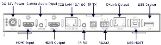
FIG. 6 TRANSMITTER PANEL DESCRIPTION
To attach signal, transport, and control cables to the Transmitter:
- Set DIP switch toggles if necessary (for settings, see the previous page).
- HDMI In – Attach an HDMI cable from the source to the HDMI In connector.
- DXLink connector – Attach a twisted pair cable to the DXLink output and to a DXLink input connector on the switcher (or on the RX for a standalone pair).
- Stereo Audio In jack (optional) – Insert analog audio cable from source.
- HDMI Output (optional) – Insert an HDMI cable from the display to HDMI Out connector.
- ICS LAN10/100 port (optional) – Use to attach twisted pair cable to LAN.
Receiver panel description and installation steps:
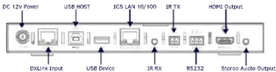
FIG. 7 RECEIVER PANEL DESCRIPTION
To attach signal, transport, and control cables to the Receiver:
- Set DIP switch toggles if necessary (for settings, see previous page).
- DXLink input connector – Attach a twisted pair cable from the DXLink output connector on the switcher (or on a TX) to the DXLink Input.
- HDMI Out - Attach HDMI cable from this port to the destination.
- Stereo Audio Out Jack (optional) – Connect analog audio cable from port to destination.
Applying Power
A desktop power supply is provided with each module. Power can be supplied to DXLink Twisted Pair Modules in the following ways:
• Over local power by connecting the supplied desktop power supply to the 12V input
• Over the DXLink connection from a powered DXLink port on a DGX or DVX
• Over the DXLink connection using a PS-POE-AT-TC (FG423-84) or PDXL-2 (FG1090-170).
Note: Local power takes precedence over DXLink power.
Power Budget: For TXs and/or RXs connected to an Enova DGX, use the Enova DGX Configuration Tool (www.amx.com/enova) to determine power requirements of a configuration and if any DXLink TXs or RXs should use the local power. The tool contains instructions on how to use it.
IMPORTANT: If a desktop power supply is used to power the unit, it must be the one provided, which must not be altered in any way. AMX does not support the use of any other power supplies or PoE injectors as they may potentially damage the DXLink equipment.
LED Status Indicators:
| INDICATOR LEDS | NORMAL POWER UP | INDICATES |
| Power | Green | Power is applied |
| Status (NetLinx) Indicator | Green | Controller is programmed and communicated properly |
| HDCP Indicator | Yellow (On/Blinking ) | HDCP-protected content is being transmitted or not |
| RX - Scaling | Blue or Off | Scaling on or off |
| Netlinx Link/Act | Green (On/Blinking - #3 Toggle OFF) | Active LAN connection to an AMX Network or receiving Ethernet data packets |
DXLink Auto-setup with Enova DGX 100 Series Switchers
Auto-setup is the default for using DXLink Modules with Enova DGX 100 Series Switchers. When all of the following conditions are met, the modules automatically go into Auto-setup Mode and can communicate through the ICS LAN port with the integrated Controller:
- Endpoints must be set to DHCP Mode (default) and use the NDP connection mode (default).
- Endpoints must not be bound to a Controller.
IMPORTANT: On the switcher, the ICS LAN port acts as a DHCP server (private LAN) and the LAN 100/1000 port acts as a DHCP client (public LAN) with each port on a separate network. In order to avoid a Network Loop, do not connect any device on the private network to any branch on the public network.
IP Addressing Modes
DHCP Mode (enabled when #3 Toggle is flipped ON)
In DHCP Mode, the Module attempts to get a DHCP lease (consisting of an IP address, gateway, and other network parameters). If the attempt fails, the Module configures itself for a link-local address, but periodically re-tries DHCP and re-assigns the IP to a valid DHCP grant if successful. At any time, if the Module determines that its IP address has changed, it will disconnect and reconnect to the Controller.
Static IP Mode (set with ID button or Telnet command)
With #3 Toggle set to ON, press ID for 10 seconds to assign address or use a Telnet command to set unit to Static IP Mode (see the manual).
Enova DGX/DVX and DXLink IP Setup (systems without auto-setup)
To setup DXLink Modules with an Enova DGX or DVX without auto-setup, you must configure the Device ID for each connected DXLink module and then connect (bind) the modules to the DGX or DVX unit. Complete instructions for DXLink setup on systems that don't support auto-setup can be found in the Hardware Reference Manual – DXLink Twisted Pair 4K60 Transmitter/Receiver.
RS-232 Serial Data (Optional)
The 232 port label is relative to data flow. Data enters at RX label on the Transmitter, is sent via a DXLink cable through the switcher, and leaves at TX label on Receiver. Flow is vice versa from Receiver to Transmitter. Applies to all DXLink modules – wire RS-232 port for serial data transfer according to pinout above connectors (TXD-RXD-Ground).
IR Control (Optional)
The IR Receiver connects to the IR RX port on the Transmitter and the IR Emitter connects to the IR TX port on the Receiver or vice versa, depending on the installation. The signal is sent via DXLink cable through the switcher.
When a Transmitter and Receiver are used as a standalone pair, IR control acts as a passthrough.
Configuring and Using USB Ports
- Each TX and RX has a Host Port (USB-B) and a Device Port (USB-A), but only one port is active at a time depending on the position of the USB DIP Switch.
- The active USB port is set by the USB DIP Switch on the front panel of the TX/RX. The default setting is TX as Host, RX as device.
- Set the USB Mode to Host when connecting to a USB host like a PC. Set the USB Mode to Device when connecting to USB devices like keyboards, mice or cameras.
- When connecting to a DGX DXLink 4K60 input/output board or a DVX-4K Presentation Switcher, the DGX or DVX will automatically detect the setting on the TX/RX and will set the function of the associated Micro-USB A/B portaccordingly.
- Some USB2.0 devices can only be powered by the TX/RX USB port when the TX/RX is powered via the local power connector.
Note:
- A reboot is required for changes to the USB Mode switch to takeeffect.
• USB ports can also be used to upgrade firmware. See Hardware Reference.
• See the detail white list for supported HID device at www.amx.com. - When a TX and RX are connected point-to-point, the USB mode switches on the TX and RX cannot be set to the same mode.
ID Button (Front)
The ID button on the front can be used to toggle between static and DHCP IP addressing, assign a device address, reset the factory defaults, and restore the factory firmware image (for details, see the manual).
Additional Information Covered in Manual
For information on the following, see the Hardware Reference Manual – DXLink Twisted Pair 4K60 Transmitters/Receiver at www.amx.com.
- NetLinx control and programming commands; Telnet commands;
- IR file transfers; upgrading firmware image; restoring factory defaultsettings;
• Web UI configurations.
Important Safety Information
Get the newest EC and FCC Declaration of Conformity at www.amx.com

Last Revised: 2020/12/14
© 2020 Harman. All rights reserved. SmartScale, NetLinx, Enova, AMX, AV FOR AN IT WORLD, and HARMAN, and their respective logos are registered trademarks of HARMAN. Oracle, Java and any other company or brand name referenced may be trademarks/registered trademarks of their respective companies.
AMX does not assume responsibility for errors or omissions. AMX also reserves the right to alter specifications without prior notice at any time. The AMX Warranty and Return Policy and related documents can be viewed/downloaded at www.amx.com.
3000 RESEARCH DRIVE, RICHARDSON, TX 75082 AMX.com | 800.222.0193 | 469.624.8000 | +1.469.624.7400 | fax 469.624.7153 AMX (UK) LTD, AMX by HARMAN - Unit C, Auster Road, Clifton Moor, York, YO30 4GD United Kingdom • +44 1904-343-100 • www.amx.com/eu/
5121555 REV:8


- DIP Switch Toggles - Default OFF (for Auto-setup, see next page)
- Overview
- System Setup
- Mounting Options (Rack Trays and Mounting Brackets)
- Twisted Pair Cable Pinouts and RJ-45 LEDs
- Attaching Signal, Transport, and Control Cables
- To attach signal, transport, and control cables to the Transmitter:
- To attach signal, transport, and control cables to the Receiver:
- Applying Power
- DXLink Auto-setup with Enova DGX 100 Series Switchers
- IP Addressing Modes
- DHCP Mode (enabled when #3 Toggle is flipped ON)
- Static IP Mode (set with ID button or Telnet command)
- Enova DGX/DVX and DXLink IP Setup (systems without auto-setup)
- RS-232 Serial Data (Optional)
- IR Control (Optional)
- Configuring and Using USB Ports
- Note:
- ID Button (Front)
- Additional Information Covered in Manual
- Important Safety Information
Brand : AMX
Model : DX-TX-4K60
Category : Extendeur AV