Pick your language and provide your email: we'll send you a specifically translated version.
This manual is not available in your language
Product Type
Alarm System
Brand
FBT
Model
VAIE 7500
Dimensions (Control Panel)
250 x 200 x 50 mm
Weight (Control Panel)
1.2 kg
Power Supply
AC 230V, 50Hz; backup battery 12V 7Ah
Power Consumption
Standby: 15W, Alarm: 25W
Number of Zones
8 wired zones, expandable to 16
Wireless Support
Up to 32 wireless detectors (868 MHz)
Siren Output
105 dB internal siren, external siren support
Communication
GSM/GPRS module optional, SMS alerts
Main Functions
Intrusion detection, panic alarm, fire detection, tamper protection
Control Interface
LCD display, keypad, remote control (RF)
Operating Temperature
-10°C to 50°C
Operating Humidity
Up to 85% non-condensing
Maintenance
Check battery annually, test sensors monthly
Security Features
Tamper switches, password protection, encryption
Spare Parts & Repairability
Batteries, sensors, remotes available; service centers in major cities
Warranty
2 years limited warranty
Compliance
CE, RoHS
Frequently Asked Questions - VAIE 7500 FBT
How do I reset the alarm after a false trigger?
Enter your master code on the keypad and press the 'Disarm' button. If the siren continues, check the zone that triggered and clear the detector.
Can I add wireless sensors to the VAIE 7500?
Yes, the system supports up to 32 wireless detectors (868 MHz). Refer to the manual for pairing instructions.
What should I do if the keypad is unresponsive?
First, check if the system is powered. Try a hard reset by disconnecting the backup battery and mains power for 30 seconds.
How do I change the backup battery?
Open the control panel enclosure, locate the 12V 7Ah lead-acid battery, disconnect the terminals, and replace with the same type. Reconnect and close.
Can the system send SMS alerts?
Yes, with the optional GSM/GPRS module. You can program up to 5 phone numbers to receive alarm SMS.
What is the maximum distance for wireless sensors?
In open space, up to 200 meters. Walls and obstacles reduce range. For best performance, keep sensors within 50 meters of the panel.
How do I set the time and date?
Press 'Menu', navigate to 'System Settings', then 'Time/Date'. Use the keypad to enter the correct values and confirm.
Why does the alarm trigger randomly?
Possible causes: low battery in a sensor, improper mounting, or pet movement. Check sensor alignment and sensitivity settings.
Can I use the system without a landline?
Yes, the control panel works standalone. For remote monitoring, use the GSM module or a broadband communicator.
How do I clear a memory fault?
View the alarm memory by pressing 'History'. To clear, enter your master code and select 'Clear Memory'. This erases all past events.
User questions about VAIE 7500 FBT
0 question about this device. Answer the ones you know or ask your own.
Ask a new question about this device
No questions yet. Be the first to ask one.
Download the instructions for your Alarm system in PDF format for free! Find your manual VAIE 7500 -
FBT and take your electronic device back in hand. On this page are published all the documents necessary for the use of your device. VAIE 7500 by FBT.
USER MANUAL VAIE 7500 FBT
VAIE 7502 500W / 2 ZONE
VAIE 7504 500W / 4 ZONE
VAIE 7506 500W / 6 ZONE
INSTRUCTIONS FOR USE
TABLE OF CONTENTS
1. WARNINGS 4
1.1 Power supply and earthing 4
1.2 Safety notes 4
2. INTRODUCTION 5
2.1 Overview of the system 5
2.2 Functional features 5
2.3 Typical configuration 6
3. GENERAL DESCRIPTION 7
3.1 Front panel 7
3.2 Inside view 8
4. INSTALLATION AND CONNECTIONS
4.1 Wall mounting 9
4.2 Connections 10
4.2.1 Connection of emergency units 11
4.2.2 Connection of paging units 11
4.2.3 Connection to other VAIE 7500 units 12
4.2.4 Connection of auxiliary input 12
4.2.5 Connection of music input 13
4.2.6 Connection of input contacts 13
4.2.7 Connection of relay outputs 14
4.2.8 21 to 29V connection 14
4.2.9 Connection of loudspeaker lines 14
4.2.10 Connection of standby amplifier 15
4.2.11 Connection of power supplies 17
5. OPERATIONAL CONDITIONS AND TERMINOLOGY
5.1. Signalling of operating conditions 18
6. DEFINITIONS
7. MENU STRUCTURE
8. USING THE SYSTEM
8.1. Conf i guration of the system 21
8.2. Menu 25
8.3.
9. FAILURE STATUS
9.1. System operation and signalling in a generic failure condition 47
9.2. System operation and signalling with a fault on a loudspeaker line 47
10. TECHNICAL SPECIFICATIONS
48
1. WARNINGS
1.1 POWER SUPPLY AND EARTHING
These items of equipment are intended to work on a 230 VAC +10% / -15%, 50/60 Hz mains voltage and a 24 VDC supply from the internal batteries.
N.B. – FEATURES OF THE WIRING SYSTEM
The mains AC power MUST be supplied through a two-pole differential thermal-magnetic circuit breaker with a current of 10 to 16A dedicated SOLELY to the equipment.
N.B.
These devices have been designed to be connected to an earthed power supply.
Make sure that the equipment is always connected to earth in accordance with legal regulations.
1.2 SAFETY NOTES
All FBT equipment is made according to the strictest international standards and complies with European Union requisites. For correct and effective use of the equipment it is important to be aware of all the characteristics by reading carefully these instructions and warnings. While the equipment is in use, it is necessary to ensure adequate ventilation, above all leaving the slits for providing air for the cooling fans free.
REFER TO THE 'INSTALLATION AND CONNECTIONS' SECTION FOR THE RELEVANT PROCEDURES, TO BE CARRIED OUT BY TRAINED SPECIALISED PERSONNEL ONLY.
Important information for correct disposal of the product in accordance with EC Directive 2002/96/EC
his product must not be disposed of as urban waste at the end of its working life. It must be taken to a special waste collection centre licensed by the local authorities or to a dealer providing this service. Separate disposal of electric and/or electronic equipment (WEEE) will avoid possible negative consequences for the environment and for health resulting from inappropriate disposal, and will enable the constituent materials to be recovered, with significant savings in energy and resources. As a reminder of the need to dispose of this equipment separately, the product is
marked with a crossed-out wheeled dustbin.
This product is in keeping with the relevant European Community Directives.
2. INTRODUCTION
2.1 OVERVIEW OF THE SYSTEM
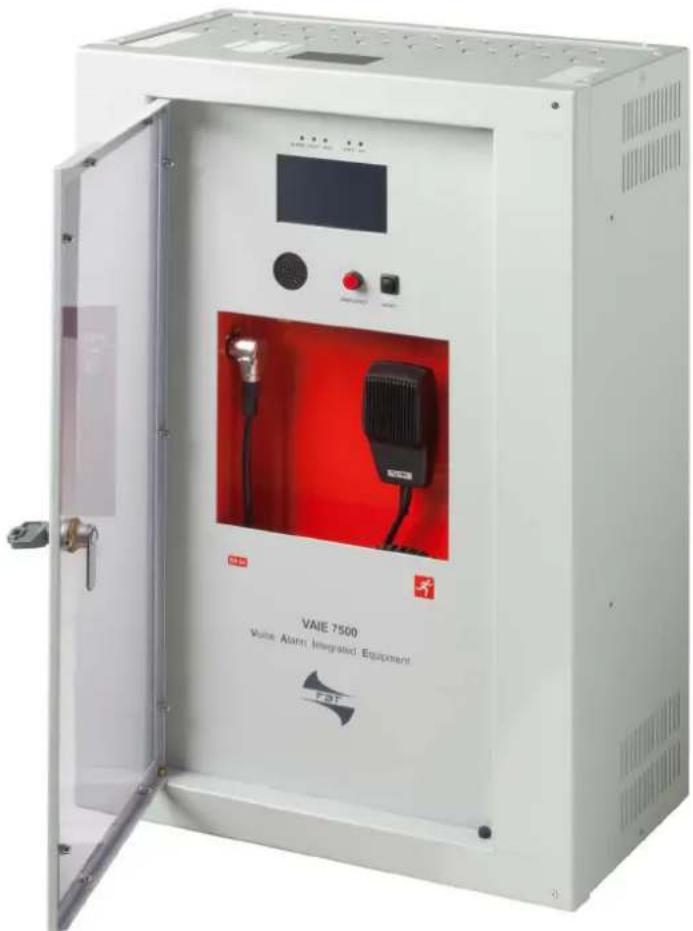
The new VAIE 7500 range includes three integrated voice evacuation systems for emergency facilities, designed specifically for wall-mounting and equipped with control units, certified in compliance with EN 54-16:2008 / EN 54-4 standards. Depending on the model, these systems are capable of managing from 2 to 6 alarm zones, each driven by a single amplifier, as well as remote microphone stations and controlled inputs to be connected to a central fi re-fi ghting system.
It is possible to connect up to a maximum of 6 of these systems to one other (for managing an overall maximum of 36 zones).
2.2 FUNCTIONAL FEATURES
Rated audio output: 500 W overall, distributable freely among the zones with a maximum limit of 250 W per single zone.
Backlit 4.3" display with touch screen for selecting the alert and evacuation zones and enabling navigation for adjusting volume levels, confi guring the equipment and viewing failures.
- Handheld fireman's paging microphone.
- Sending out of pre-recorded EVACUATION and ALERT messages.
- Sending out of pre-recorded BROADCAST messages (i.e. spots, announcements, sound bells).
- Playing back of pre-recorded messages via monitor loudspeaker.
- 7 off controlled input contacts, configurable for playing the evacuation and/or alert messages to the programmed zones or for resetting the messages.
• 1 off music input for sound sources.
- 1 off auxiliary input configurable as a music source, a call with precedence activation or a call with automatic activation (VOX).
• 3 off confi gurable relay outputs.
• Double A+B output for each zone.
- Event log (list of failures and/or alarms that have occurred in the system).
- Double LINK line for connecting other VAIE 7500 (up to a total of 6 units).
• Multilanguages management.
- Protected local button for placing the system in an emergency state, equipped with its own LED.
- Local reset button.
• 3-band equalisation for each zone output.
• 3-band equalisation for each music input.
- Optional internal expansion card for two additional music inputs (EXT 1 and EXT 2).
- Optional internal expansion card with DSP for six additional music inputs.
• Built-in SD/USB input for background music MP3 player.
- Independent selection on each zone of the various audio sources (MUSIC IN, AUX IN, MP3 player and EXT).
- Up to 8 pre-recorded messages can be retrieved from outside through input contacts (of which 2 fixed emergency messages - plus 6 that can be classed as emergency / evacuation / broadcast messages).
- Possibility of setting up to 16 timers for the programmed playing out of the broadcast messages with the possible activation of signalling relays.
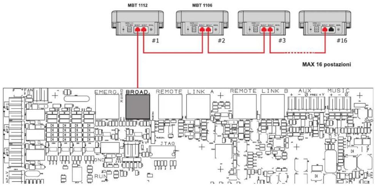
- Up to 16 MBT 1106 and/or MBT 1112 broadcasting microphone stations can be connected.
- Up to 4 of the above mentioned stations can be set for local calls only (zones of the card-cage to which they are connected).
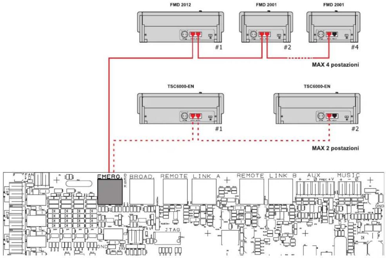
- Up to 4 FMD 2001 and FMD 2012 remote emergency units can be connected (or, as an alternative, up to 2 touch screen units TSC6000-EN).
- EN54-4 certifi ed battery charge unit for 24VDC secondary power supply (batteries not included).
- Mounting on 19" rack (optional, with accessory kit).
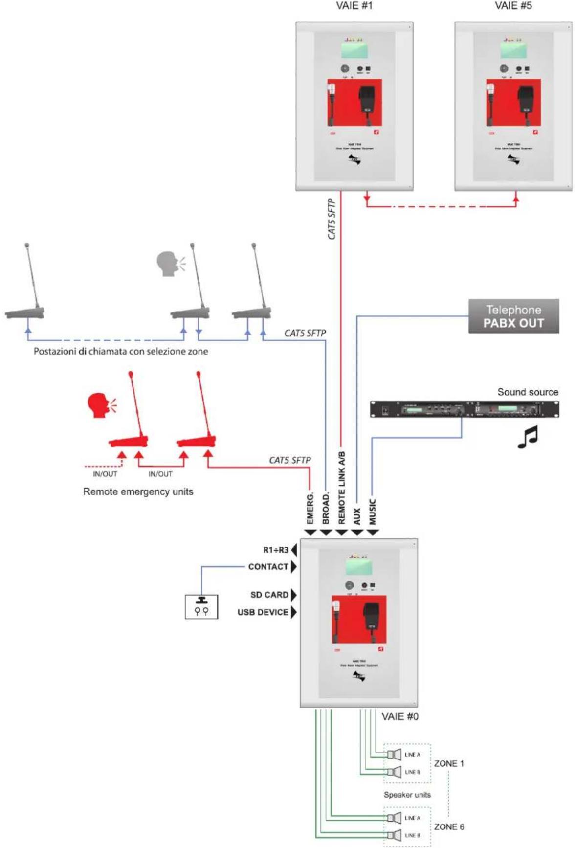
2.3 TYPICAL CONFIGURATION
flowchart
graph TD
    A["VAIE #1"] -->|CAT5 SFTP| B["Remote emergency units"]
    C["VAIE #5"] -->|CAT5 SFTP| B
    B -->|IN/OUT| D["Postazioni di chiamata con selezione zone"]
    B -->|IN/OUT| E["Remote emergency units"]
    B -->|CAT5 SFTP| F["Telephone PABX OUT"]
    F --> G["Sound source"]
    G --> H["MUSIC"]
    H --> I["VAIE #0"]
    I --> J["Speaker units"]
    I --> K["ZONE 6"]
    I --> L["ZONE 1"]
    I --> M["LINE A"]
    I --> N["LINE B"]
    I --> O["Line A"]
    I --> P["Line B"]
    I --> Q["R1÷R3"]
    I --> R["CONTACT"]
    I --> S["SD CARD"]
    I --> T["USB DEVICE"]
3. GENERAL DESCRIPTION
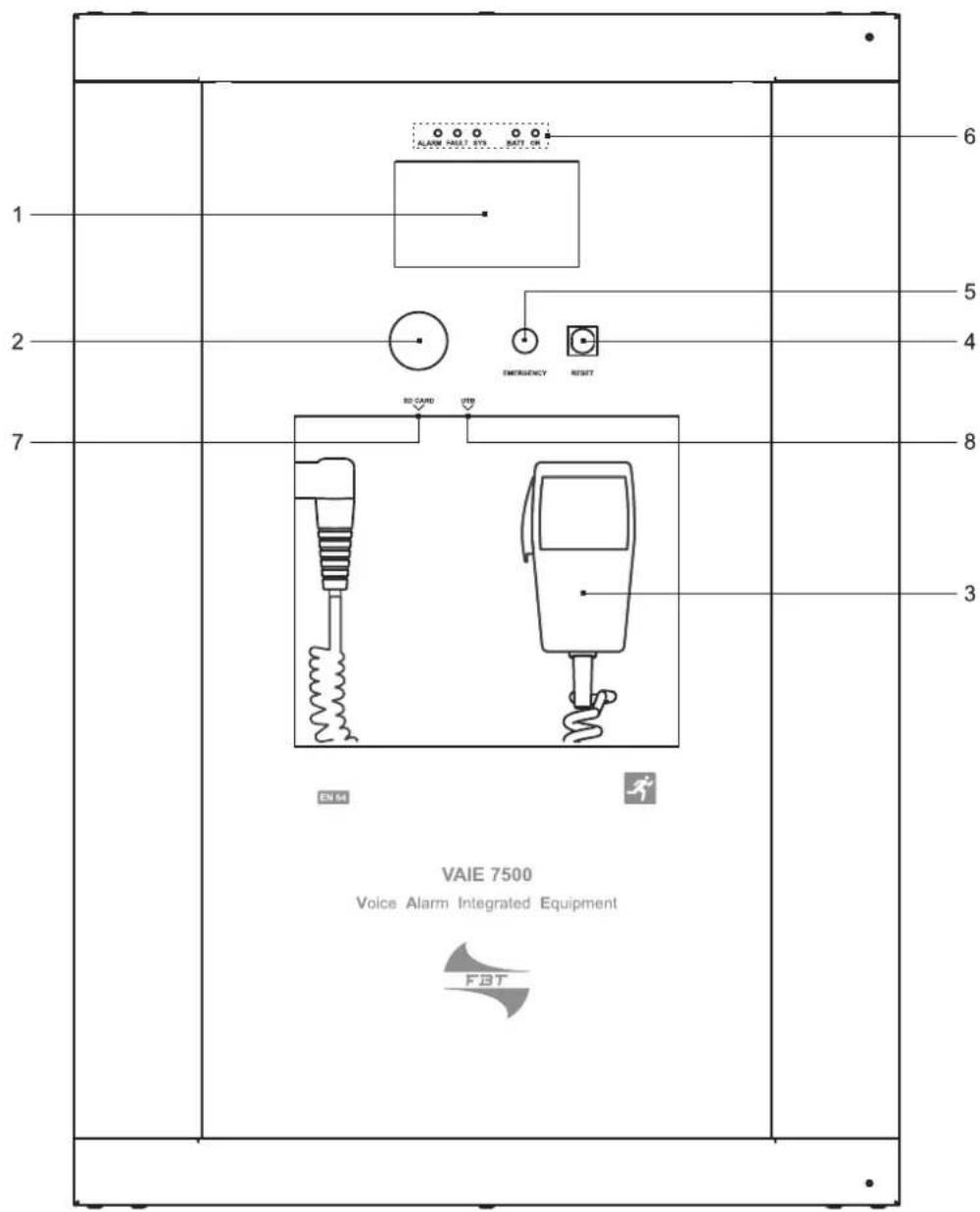
3.1 FRONT PANEL
1) Backlit 4.3" display with touchscreen for selecting the Alert/Evacuation zones and for navigation for adjusting volume levels, confi guring the equipment and viewing failures.
2) Integrated loudspeaker for playing back the output signals from the zones or the signals of the input sources and for replaying the acoustic signal indicating that a failure has been detected (beep). The signalling tone will be automatically muted if the conditions of failure end. Furthermore, in accordance with the regulations, the beep is muted by the system while the Emergency Microphone is being used.
3) Handheld fi reman's paging microphone.
4) RESET button.
5) EMERGENCY button.
6) Status LEDs.
7) SD card slot.
8) USB socket for external device.
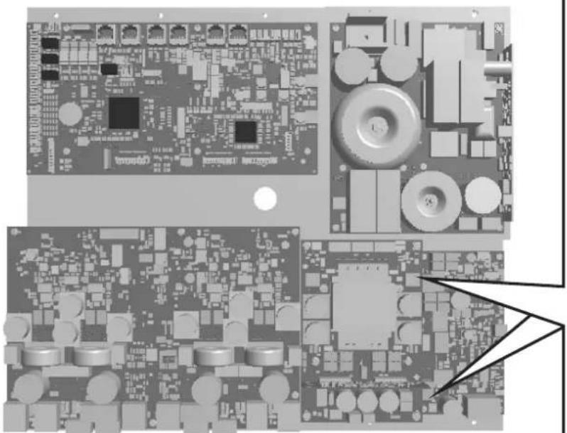
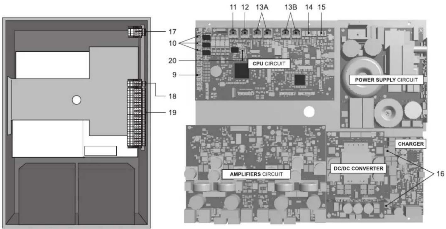
3.2 INSIDE VIEW
9) 7 off controlled input contacts.
10) 3 off relay output contacts.
11) Input for emergency microphone stations (max. 4).
12) Input for paging microphone stations (max. 16).
13) Input/output sockets REMOTE LINK A/B for connection to other VAIE 7500 units (overall max. of 6).
14) Input terminal strip for auxiliary sources with precedence contact.
15) Input terminal strip for music sources.
16) Connection to 24 VDC battery power.
17) Connection to 230 VAC power supply.
18) Connection of standby amplifier.
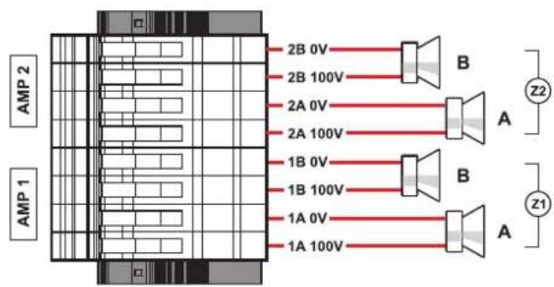
19) Connection of loudspeakers lines.
20) Terminal strip for 21 to 29 V connection.
4. INSTALLATION AND CONNECTIONS
! N.B.
Please remind that the operations illustrated in this part of the manual must be carried out by specialised personnel ONLY, trained and qualified in the equipment installation and maintenance. When the VAIE is opened, parts entailing a high risk of electric shocks become accessible.
It is advisable to install the equipment in a closed and sheltered place, protected against possible sources of damage (rain, moisture, high temperatures, etc.).
Depending on requirements, the cables can be inserted by eliminating either the plugs sealing the holes in the top or the rear door (in both cases use a fl at screwdriver or a cutter to lift them and remove them).
It is important to keep the power cables separate from those dedicated to the other connections.
4.1 WALL MOUNTING
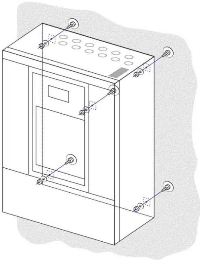
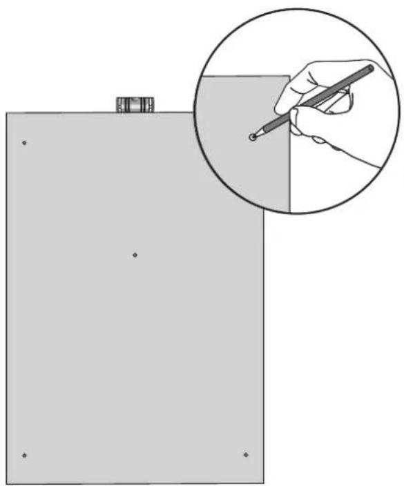
Take the cardboard template included in the package and position it at a suitable height so that it is accessible to the user. Ideally, the front display should be at eye level.
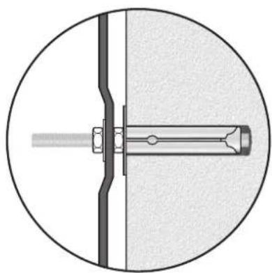
Having decided on the position, mark the fi ve points on the wall and fi t Fischer wall plugs (min. ∅ 9 mm) equipped with bolts into them.
Using the wall plugs as reference pins, lift the equipment and hook it to the wall. It is advisable for this activity to be carried out by two people.
Tighten the bolts.
natural_image
Technical line drawing of a cabinet or enclosure with mounting holes and ventilation grilles (no text or symbols)
natural_image
Diagram showing a hand holding a pen writing on a line, with an inset magnified view of the pen tip (no text or symbols present)
natural_image
Cross-sectional diagram of a mechanical assembly with a central shaft and bolted joint (no text or labels)
NOTE:
For rack mounting, it is necessary to use the relevant optional accessory and to follow the indications provided on its instruction sheet.
4.2 CONNECTIONS
! N.B.
Check that the main thermal-magnetic circuit breaker is switched OFF.
If it is not, switch it OFF before carrying out any other activities in the cabinet as there is a danger of electric shocks.
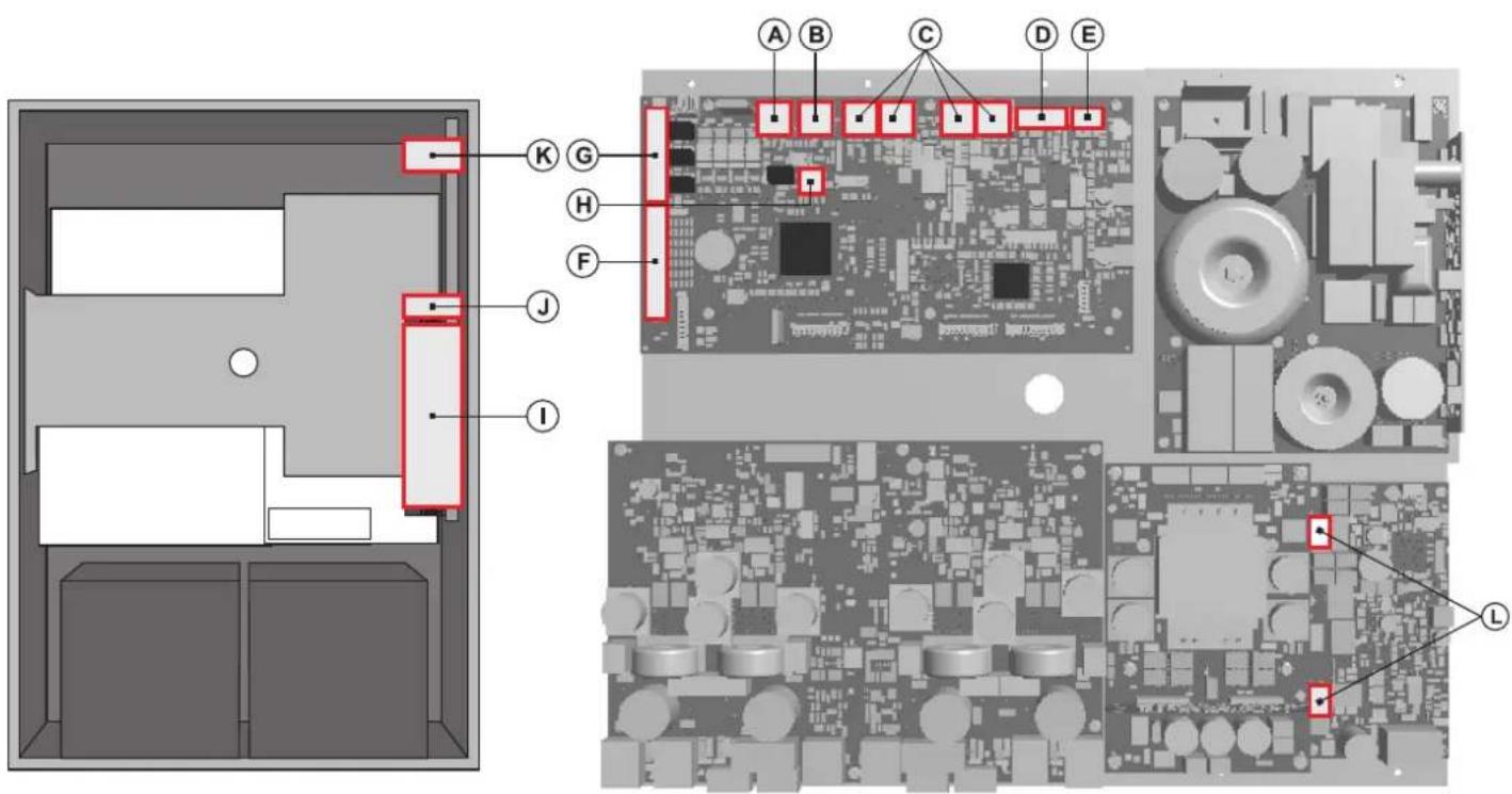
Proceed with connection of the various devices, referring to the appropriate points of the manual:
CPU circuit
A) Point 4.2.1 Connection of emergency units (page 11)
B) Point 4.2.2 Connection of paging units (page 11)
C) Point 4.2.3 Connection to other VAIE 7500 systems (page 12)
D) Point 4.2.4 Connection of auxiliary input (page 12)
E) Point 4.2.5 Connection of music input (page 13)
F) Point 4.2.6 Connection of input contacts (page 13)
G) Point 4.2.7 Connection of relay outputs (page 14)
(H) Point 4.2.8 21 to 29V connection
(page 14)
AMPLIFIER circuit
H) Point 4.2.8 Connection of the loudspeaker lines (page 14)
I) Point 4.2.9 Connection of the standby amplifier (page 15)
Once the basic connections have been made, it is possible to go on to connect the power supplies:
J/K) Point 4.2.10 Connection of power supplies (page 17)
N.B.: It is essential to follow the correct sequence for powering up the equipment, failing which it could be damaged.
4.2.1 CONNECTION OF EMERGENCY UNITS [CPU CIRCUIT]
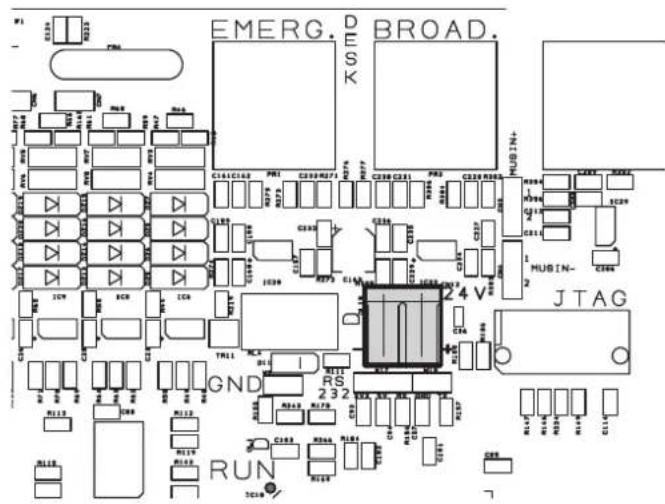
Use a CAT. 5e SF/UTP cable for connecting the EMERG. socket (11) to the 'IN/OUT' sockets of the FMD remote emergency units (up to 4). As an alternative, it is possible to connect up to 2 touch screen units TSC6000-EN. The length of the link between the card-cage and the last station must not exceed 1000 metres at most.
4.2.2 CONNECTION OF PAGING UNITS [CPU CIRCUIT]
Use a CAT. 5e SF/UTP cable for connecting the BROAD. socket (12) to the 'IN/OUT' sockets of the MBT 1106 / MBT 1112 paging units. The length of the link between the card-cage and the last station must not exceed 1000 metres at most.
4.2.3 CONNECTION TO OTHER VAIE 7500 UNITS [CPU CIRCUIT]
Use CAT. 5e SF/UTP cables for connecting other VAIE 7500 units (up to a maximum total of 6 per system) via the REMOTE LINK A/B sockets (13). The length of the link between the first card-cage and the last unit must not exceed 1000 metres at most.
flowchart
graph TD
    subgraph_VAIE_750x_1["VAIE 750x"]
        A1["LINK A IN OUT"] -->|Red Arrow Down| B1["VAIE 750x"]
        A2["LINK B IN OUT"] -->|Red Arrow Up| B2["VAIE 750x"]
    end
    subgraph_VAIE_750x_2["VAIE 750x #2"]
        C1["LINK A IN OUT"] -->|Red Arrow Down| D1["VAIE 750x"]
        C2["LINK B IN OUT"] -->|Red Arrow Up| D2["VAIE 750x"]
    end
    A1 -->|Red Arrow Down| B1
    A2 -->|Red Arrow Up| B2
    C1 -->|Red Arrow Down| D1
    C2 -->|Red Arrow Up| D2
    style A1 fill:#f9f,stroke:#333
    style A2 fill:#f9f,stroke:#333
    style C1 fill:#ccf,stroke:#333
    style C2 fill:#ccf,stroke:#333
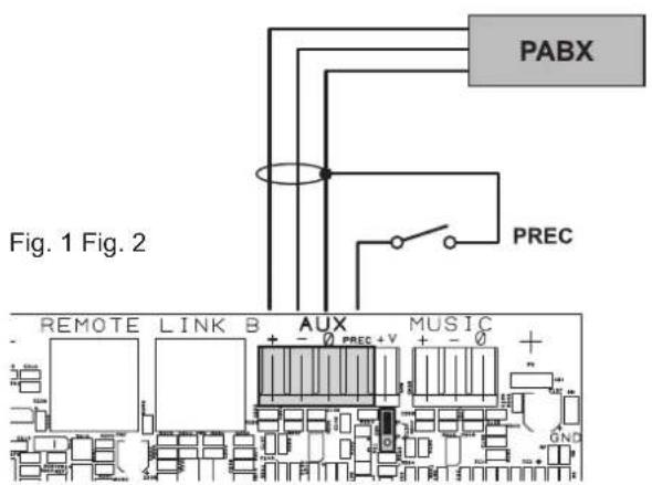
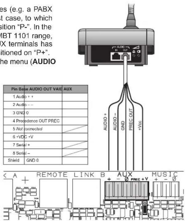
4.2.4 CONNECTION OF AUXILIARY INPUT [CPU CIRCUIT]
The AUX terminals (14) are available for connecting auxiliary sources (e.g. a PABX or a base for announcements with a precedence contact). In the first case, to which Fig. 1 refers, it is necessary to fit a jumper onto connector CN9 in position "P-". In the second case, on the other hand, using a pre-amplified station of the MBT 1101 range, connection between the AUDIO OUT socket of the base and the AUX terminals has to be made as indicated in Table 1 and the jumper will have to be positioned on "P+". NOTE: Selection between modes P- and P+ must be made also via the menu (AUDIO SETTING > set>AUX, CHIME, page 27).
For details concerning connection and the colours of the wires, refer to the manual of the MBT 1101 base range (code FBT 37781).
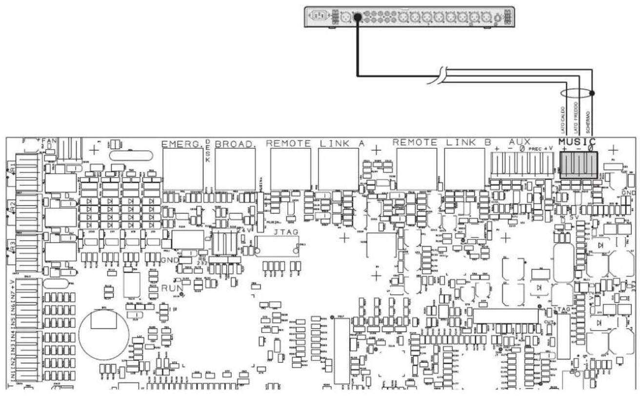
4.2.5 CONNECTION OF MUSIC INPUT [CPU CIRCUIT]
The MUSIC terminals (15) are available for connecting outside music sources (CD player, tuner etc.).
4.2.6 CONNECTION OF INPUT CONTACTS [CPU CIRCUIT]
There are 7 input contacts on the CONTACT terminal strip (9): the figure shows an example of a connection in which contacts 1, 2, 3, 5 and 6 are of the monitored type while contacts 4 and 7 are not.
flowchart
graph TD
    A["CONT.1"] --> B["R1 10K"]
    A --> C["R2 10K"]
    B --> D["R3 10K"]
    C --> E["R4 10K"]
    D --> F["R5 10K"]
    E --> G["R6 10K"]
    H["CONT.2"] --> I["R7 10K"]
    H --> J["R8 10K"]
    I --> K["CONT.3"]
    J --> L["CONT.4"]
    K --> M["+Vcc"]
    L --> M
    M --> N["CONT.4"]
    M --> O["CONT.7"]
    N --> P["CONT.6"]
    O --> Q["CONT.6"]
    P --> R["CONT.5"]
    Q --> S["CONT.5"]
    R --> T["+Vcc"]
    S --> U["+Vcc"]
    T --> V["CONTACT"]
    U --> V
    V --> W["LCD"]
4.2.7 CONNECTION OF RELAY OUTPUTS [CPU CIRCUIT]
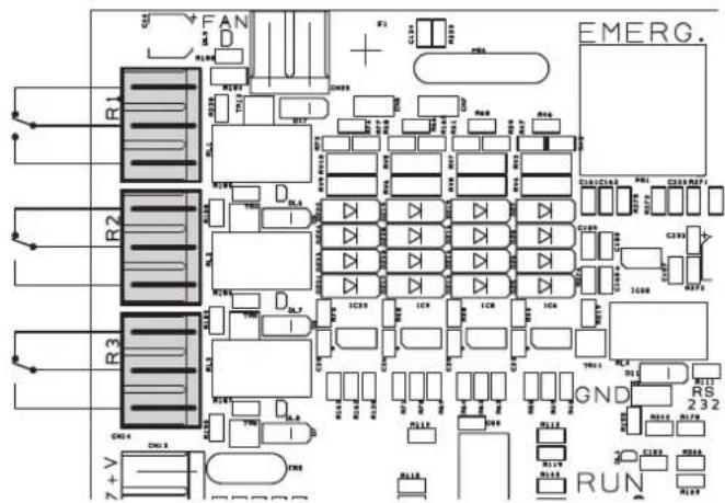
Three relay outputs are available on terminals R1, R2 and R3 (10) for signalling towards outside peripheral units.
4.2.8 21 TO 29 V CONNECTION [CPU CIRCUIT]
Depending on how the VAIE will be working, it is possible to receive a 21 to 24V power supply on the 24V terminals (20), with a maximum absorption of 50 mA.
4.2.9 CONNECTION OF LOUDSPEAKER LINES
[AMPLIFIERS CIRCUIT / TERMINAL STRIP]
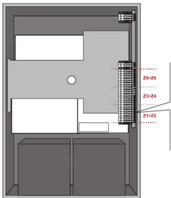
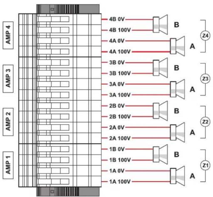
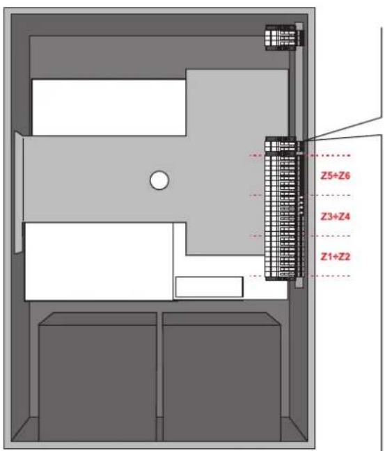
Terminals A/B (19) are dedicated terminals for connection of the loudspeaker lines. The wiring of a VAIE 7502 model (2 zones) is shown in the figure below.
VAIE 7502
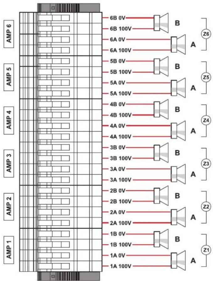
The connections for 4 and 6 zone models (respectively VAIE 7504 and VAIE 7506) are shown in this figure.
VAIE 7504 VAIE 7506
4.2.10 CONNECTION OF THE STANDBY AMPLIFIER [TERMINAL STRIP]
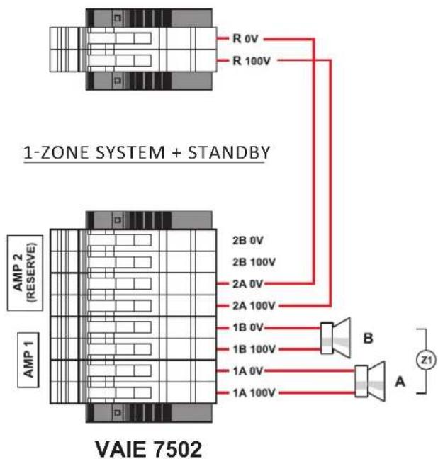
Using both terminal strip R (18) and A/B (19) it is possible to set a standby amplifier: here's the connection of a VAIE 7502 model (1 zone + standby amplifier). In the following pages, the connections for VAIE 7504 model (3 zones + standby amp) and VAIE 7506 (5 zones + standby amp).
Check that the main thermal-magnetic circuit breaker is switched OFF. If it is not, switch it OFF before carrying out any other activities in the cabinet as there is a danger of electric shocks.
!N.B.
These devices have been designed to be connected to an earthed power supply. Make sure that the equipment is always connected to earth in accordance with legal regulations.
It is essential to follow the correct sequence for powering up the equipment, failing which it could be damaged.
1> Check that the main thermal-magnetic circuit breaker is switched OFF.
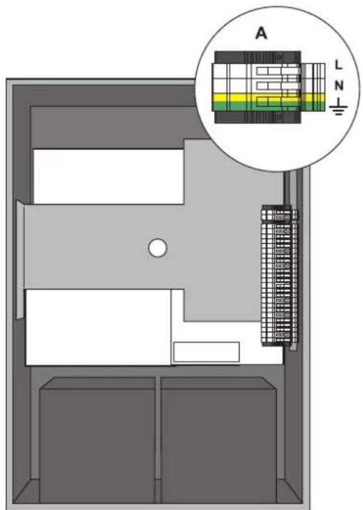
2> Connect the power cable coming from the thermal-magnetic circuit breaker and the earth cable to the contacts on the terminal strip (A) - see figure.
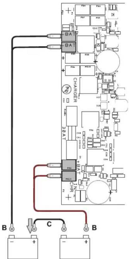
3> Connect the external terminals (B) of the batteries, observing the correct polarities.
4> Switch the thermal-magnetic circuit breaker ON.
natural_image
Top-down view of a printed circuit board with various components and traces (no visible text or symbols)
5> Make a jumper between the inside terminals of the batteries using the cable (C) included in the supply
6> Close the front door, tightening the screws firmly.
From now on the VAIE is working.
NOTE:
If the front door is opened, the amplifiers are deactivated automatically, and can be re-activated by specialised personnel only by using a specific menu item.
5. OPERATIONAL CONDITIONS AND TERMINOLOGY
Following is a list of how the operating conditions of the system are signalled and of the definitions used on the subsequent pages of the manual, completed by indications of a general nature.
5.1 SIGNALLING OF OPERATING CONDITIONS
The VAIE is designed to signal the different operating conditions as defined below:
Idle state (ALARM, FAULT and SYS LEDs off)
Normal operating condition, with no current faults or emergencies.
Alarm Status (ALARM LED on)
Operating condition signalling the presence of at least one alarm signal, either pre-recorded or live, in at least one output zone.
Faulty status (FAULT LED on)
Operating condition signalling the presence of at least one fault detected by the internal diagnostic system, with the relevant LED turning on.
System failure (SYS LED on)
Operating condition signalling that the system has crashed due to temporary or permanent CPU malfunctioning, detected by the watchdog device.
Automatic Emergency (Display showing 'AUTOMATIC EMERGENCY' with active zones)
Sequence of operations recalled by an external peripheral unit connected to the control inputs that, depending on how these are programmed, activates the Alarm Status or resets the alarms.
Manual Emergency (LED of the EMERGENCY button steady ON or flashing)
Procedure of action on the system manual controls by an authorised operator, in order to activate emergency sources.
Operations in the Manual Emergency mode have priority over those activated in the Automatic Emergency mode.
6. DEFINITIONS
BGM source (Background Music)
One of the audio sources that can occupy the "Music" amplification channel.
PA source (Public Address)
One of the audio sources that can occupy the "Voice" amplification channel for service announcements.
Emergency Source
One of the audio sources that can occupy the "Voice" and/or "Music" channels for voice emergency announcements (pre-recorded messages announcing an Alert and/or Evacuation, live messages from the local microphone, a call from a remote emergency microphone station). Activation of an Emergency Source generates the operational condition of "State of Alarm".
Priority
Occupation of the output zones by an audio signal or a reset order is governed hierarchically by the priority level assigned to each active source. The current activation of the area can be stopped only by another with a higher priority.
7. MENU STRUCTURE
The VAIE allows system functions to be accessed through a series of Management Panels grouped, according to their operational typology and intended use, in Option Menus accessible from the MAIN MENU window. Furthermore, the following Option Menus have been assigned to different levels of access, with reference to the various circumstances requiring different degrees of skill and authorisation of the personnel assigned. In each menu it is possible to browse through the options listed by running a finger over the sidebar or pressing the 'Up' and 'Dn' (Down) buttons. To select an item, press the appropriate button. Similarly, the levels can be adjusted simply by moving the cursor along the indicator bar.
MENU | BASE LEVEL
flowchart
graph TD
    A["BACKGROUND MUSIC"] --> B["Levels"]
    A --> C["MP3 file"]
    A --> D["Main menu"]
    B --> E["No paging active"]
    F["Zone 1"] --> G["-6dB"]
    H["Zone 2"] --> I["MP3"]
    J["No"] --> K["-6dB"]
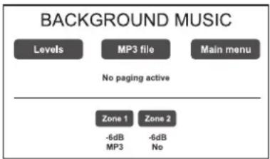
Default window for using the system in normal Idle State conditions, enabling controlling of the BGM (Background Music) sources, the selection of MP3 files from external devices (an SD card or a USB key) and adjustment of the volumes of the music section.
At this basic level, the RESET button is not operational.
This panel is shown immediately when the system is switched ON.
To access the Main Menu press the 'Main Menu' button.
For the specific features of the MUSIC menu, see page 25.
MENU | BASE LEVEL

Main menu for selecting the four VAIE operational levels.
At this basic level the RESET button is not operational.
To go back to the MUSIC Menu press the 'Music Menu' button.
To select the required item press the relevant key.
Other manuals FBT
Discover other manuals and user guides for the brand FBT
💬 Hi! I'm your manual assistant.I know your FBT VAIE 7500.
How can I help you? (use, settings, error codes, maintenance, explaining a step from the manual, etc.)💡 Examples :
• How do I use it ?
• Error code E3 ?
• How do I clean it ?









![FBT VAIE 7500 - CONNECTION TO OTHER VAIE 7500 UNITS [CPU CIRCUIT] - 1](/content/2026/05/1043914/images/725d69a430bd2cdd7dd3ce005588822d33cae1bb2a604e082e1d76243fe847b9.jpg)
![FBT VAIE 7500 - CONNECTION OF INPUT CONTACTS [CPU CIRCUIT] - 1](/content/2026/05/1043914/images/9d1b64c1dc6d371996f317385310cc9549f492537a61f9d8ec98b0812b5dba5f.jpg)