
161 - Audio Compressor DBX - Free user manual and instructions
Find the device manual for free 161 DBX in PDF.


| Type de produit | Audio Dynamics Processor |
| Marque | DBX |
| Modèle | 161 |
| Catégorie | Compresseur/Limiteur |
| Dimensions (L x H x P) | 48.3 x 4.4 x 20.3 cm (19" rack, 1U) |
| Poids | 2.3 kg |
| Alimentation | 115/230 V AC, 50/60 Hz, 20 W |
| Entrées audio | 2 x XLR (symétrique), 2 x TRS (symétrique) |
| Sorties audio | 2 x XLR (symétrique), 2 x TRS (symétrique) |
| Rapport signal/bruit | > 100 dB (A pondéré) |
| Plage dynamique | > 110 dB |
| Réponse en fréquence | 20 Hz - 20 kHz, ±0.5 dB |
| Fonctions principales | Compression, limitation, gate, expansion |
| Contrôles | Seuil, Ratio, Attack, Release, Gain Makeup, Bypass |
| Indicateurs | LED de niveau d'entrée/sortie, LED de réduction de gain |
| Entretien et nettoyage | Nettoyer avec un chiffon sec et non pelucheux. Éviter les liquides. |
| Sécurité | Débrancher avant tout entretien. Utiliser uniquement dans un environnement sec. |
| Pièces détachées et réparabilité | Contacter un service agréé DBX pour les pièces et réparations. |
| Informations générales | Conçu pour studio et sonorisation. Garantie 2 ans. |
Frequently Asked Questions - 161 DBX
User questions about 161 DBX
0 question about this device. Answer the ones you know or ask your own.
Ask a new question about this device
Download the instructions for your Audio Compressor in PDF format for free! Find your manual 161 - DBX and take your electronic device back in hand. On this page are published all the documents necessary for the use of your device. 161 by DBX.
USER MANUAL 161 DBX
INDEX
| INTRODUCTION | 2 |
| GENERAL INFORMATION | 3 |
| Models | 3 |
| Applications | 3 |
| Stereo Tracking | 4 |
| The Compressor as a Tool | 5 |
| FRONT PANEL CONTROLS & METERING | 6 |
| INSTALLATION | 7 |
| AC Power | 7 |
| Signal Connections | 7 |
| Input Impedance & Terminations | 10 |
| OPERATION | 10 |
| Power Switch | 10 |
| Threshold & Compression Ratio Adjustments | 10 |
| Output Gain Control Adjustment | 11 |
| Meter Calibration & Use | 11 |
| The 160 or 161 as a Line Amplifier | 11 |
| A REVIEW | 12 |
| SPECIFICATIONS 160 | 13 |
| 161 | 14 |
| WARRANTY | 15 |
| FACTORY SERVICE | 15 |
| GLOSSARY | 1 |
| SCHEMATICS | VII |
| ILLUSTRATIONS | VIII |
| Fig. 1 - Front Panel | 6 |
| Fig. 2A - Connecting the 160 in a Balanced Circuit | 8 |
| Fig. 2B - Connecting the 160 in an Unbalanced Circuit | 8 |
| Fig. 3A - Connecting the 161 in a Balanced Circuit | 9 |
| Fig. 3B - Connecting the 161 in an Unbalanced Circuit | 9 |
| Fig. 4 - Attack & Release Times “track” the envelope of the input signal | 12 |
| Fig. 5 - Input and Output Levels at various compression ratios | 12 |
INTRODUCTION
2
The dbx 160 and 161 are single-channel compressor/limiters combining sophisticated technology and user-oriented features in a compact package. Unique circuit designs, such as true rms level-detection and feed-forward gain reduction, place the 160 and 161 in a completely different class from conventional compressor/limiters.
The dbx technique of true rms level-detection gives you audible benefits. Most compressor/limiters use some form of peak detection, with fast response characteristics that can have a disturbing effect on program material. True rms level detection closely simulates the response of the human ear. Even at high compression ratios, the gain changing action of the 160 Series is highly listenable and natural sounding.
Because of the unique feed-forward approach, dbx 160 and 161 limiters can achieve infinite compression with complete stability and inaudible distortion. The dbx approach is quite unlike gain reduction in a conventional compressor/limiter. Traditional gain reduction is accomplished by sensing signal level at the device's output and applying a correction signal, via a feedback loop. At progressively higher compression ratios, the feedback loop's gain increases, distortion increases, and eventually instability or oscillation occurs. To avoid this problem, many conventional units restrict the maximum amount of feedback, thus restricting the maximum compression ratio to some lower ratio, such as 10:1 or 20:1. The dbx 160 and 161 are free of the instability of excessive loop gain, and can provide infinite compression (approximately 120:1).
In addition to increasing the stability and the available range of compression, dbx's feed-forward approach makes it possible for the attack and release times to "track" the signal envelope. In conventional compressor/limiters, the attack and release times depend on feedback loop gain, which means they constantly must be readjusted for optimum results at different compression ratios. Since the attack and release times of dbx units vary automatically with the rate of level change in the program material (the envelope shape), operation is simplified; no manual attack/release adjustments are required. At the same time, the "naturalness" of any given sound is better preserved.
GENERAL INFORMATION
Models
The Model 160 is a fully professional compressor/limiter with a balanced differential input, with an automatic ground-loop compensated output (hum resulting from any ground loop at the output is automatically sensed and attenuated at least 40dB), and with a special protection circuit that blocks power turn-on and turn-off transients from the output.
The Model 161 is nearly the same as the 160, but is priced for the smaller studio, or the semi-pro user. It has the same advanced rms detection and feed-forward circuitry as Model 160, but it lacks turn-on/turn-off transient protection, and ground-loop compensation. The 161's input and output are unbalanced and terminated in RCA-type phono jacks.
Both models have adjustable threshold, and a pair of LED's that indicate when the input level is above or below the threshold. An illuminated meter displays a full 60dB range and is switchable to read input level, output level, or gain change. The meter's sensitivity is continuously variable, so "zero VU" can be adjusted to equal your system's nominal operating level, anywhere from +10 to -10dB. Output line level is also adjustable, ±20dB. Maximum output on the 160 is +26dB (15.5V) into a high impedance, or +24dBm (12.3V) into 600 ohms. Maximum output on the Model 161 is +18dB (6.14V) into a high impedance, or +16dBm (4.89V) into 600 ohms.
Attractively styled and functionally designed, either model can stand alone or can be mounted in a standard 19" rack. Two units can be mounted side-by-side in just 3½" of panel space with the optional dbx RM-150-C rack mount kit; the RM-150-D is for rack mounting of a single unit.
Applications
dbx noise reduction systems now make it possible to process programs with 100dB, or greater, dynamic range. Unfortunately, in some applications it is necessary to restrict dynamic range. While dbx noise reduction systems are used in the studio, for record production, to maintain wide dynamic range, this range must often be restricted to optimize the sound for broadcast and home playback. The restriction of dynamic range is usually done with a compressor, in the final stages of recording (or record mastering). In the broadcast field, where many stations compete for an audience, a high average audio level can make a big difference to radio station ratings. Compression is used to attain high average levels. However, unless a high-quality compressor/limiter is utilized, distortion and unwanted audible side-effects may degrade the sound so badly that the advantages of high average level are overcome, and audience interest can be lost. The 160 and 161 do a great job in both recording and broadcast applications.
The dynamic range of a live musical performance can be even greater than 100dB. A high-quality compressor/limiter, used judiciously, can restrict the dynamic range, raise the average level, help the operator avoid clipping distortion, and improve the overall sound quality. Because the 160 and 161 sound so natural, they won't displease performers, making them especially well suited to sound reinforcement applications.
Compressor/limiters can be useful in other applications too. The 160 and 161 are ideal for use as a high quality line amplifier because of their low noise and distortion and high output drive. The 160 and 161 have the added advantage of allowing you to conveniently dial in compression at any time. In any application requiring high-quality compression
or limiting the dbx 160 and 161 provide superior performance at a reasonable price.
Stereo Tracking
Some compressor/limiters have jacks that ostensibly equip the units for stereo operation. The jacks "strap" the gain control sections of the two single-channel units together so that the stereo image remains stable even when the signal level is radically different in the two channels. dbx's Model 160 and 161, are not equipped for stereo operation. The lack of "strapping" provisions is no oversight; it is a well thought out engineering decision. The reason for this decision is simple, if not immediately obvious.
Stereo tracking between two separate compressor/limiters requires great accuracy. This tracking accuracy has little to do with the quality or the ability of a single-channel unit to meet its specifications. Even with better than average component tolerances, component-to-component variation is typically 10%; most potentiometers have 20% tolerances. Such tolerances are perfectly acceptable, and will not degrade the performance of an individual single-channel unit. Internal trimmers are adjusted to provide any needed correction, and any critical components are matched or have precision tolerances.
While the front panel settings of two “strapped” units may be identical, component tolerances can cause the actual performance to vary from unit to unit by as much as 20%. Even small tolerance differences will cause the stereo image to shift rapidly from right to left. These normal component tolerances only become a problem if two units are strapped together for stereo operation.
If any given pair of single-channel units ever manufactured could be strapped together for accurate stereo tracking, individual component tolerances in each unit would have to be very tightly controlled. This approach would not improve the performance of any one single-channel unit, but it would make the cost of all units prohibitive.
There are three other ways to build compressors with stereo strapping jacks: (The easy way out) Put in the jacks on production units that are not critically matched, and ignore the resulting problems: (The expensive way out) install highly accurate, precision components throughout the compressor for accurate stereo tracking performance, and charge every purchaser for the stereo capability, whether or not it is needed, or (The hard way out for you) install enough external trim-pots so that, if you had the right test equipment, you could adjust the tracking accuracy yourself . . . as often as required by component aging or touring abuse.
None of the above solutions were very palatable to dbx (nor would the results have been to you, the user). dbx decided that omitting the stereo tracking feature would improve the overall value of the product, and would help dbx to keep its commitment to product excellence at reasonable cost. There is no reason for people who need a single-channel compressor/limiter to pay for precision parts or matching that they do not need. Neither is there any reason for someone who needs a stereo compressor/limiter to accept inferior performance from units with strapping jacks but no matched or precision components that would provide precise stereo tracking accuracy.
Instead, dbx decided to offer another model, the 162, which is a two-channel compressor/limiter designed and built for the user who needs precise stereo tracking. The 162 utilizes matched components and close-tolerance parts to achieve precise tracking, with easy, single-knob adjustments. The 162 does the job at an attractive price. It makes a lot of sense when you think about it: a precise dbx
compressor/limiter for single-channel jobs, and another for precise stereo operation.
The Compressor/Limiter as a Tool
Set up properly, a compressor can be a useful device. Figure 4, Curve A shows the envelope of an input signal with no compression. (The "envelope" of a signal is a graph of its instantaneous level.) Curve B shows the envelope of the same signal after 2:1 compression has reduced its level. Curve C shows the results of extreme 20:1 compression (limiting). At this extreme compression ratio, the output level is essentially constant for any input above the threshold.
Much of the character of music is contained below the attacks or peaks. If the threshold is set 10dB or more above the average level of the input signal, then compression will take place primarily on the uppermost peaks or attacks of the signal, minimizing musical alteration. However, if the threshold is set to a level that is lower with respect to the average level, noticeable musical alteration may occur.
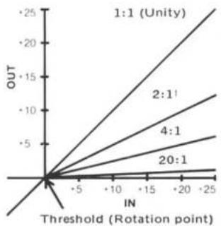
With a 2:1 compression ratio, a 2dB increase in input level (above threshold) causes the output to rise only 1dB. With a 4:1 ratio, a 4dB increase at the input results in a 1dB increase at the output. With a 10:1 ratio, a 10dB increase at the input results in a 1dB increase at the output, and so forth. Therefore, the amount of musical alteration also depends on the compression ratio used, as well as the threshold setting.
Music listening pleasure is greatest with full, unaltered dynamic range. Because dbx noise reduction systems afford a useable dynamic range of over 100dB, dbx recommends their use whenever practical. Limiting or compression can be used in conjunction with dbx noise reduction systems, for effect only.
A compressor/limiter, as with any useful tool, can be
misused. In fact, many people refuse to use compression, even when it would improve the audio quality, because they have heard compression being misused all to often. One of the nicest aspects of dbx compressor/limiters is the fact that they are easy to use and they sound better than competitive units... even when using more extreme compression.
Fig. 1 - Front Panel

*Controls and functions are identical for the Model 160 and Model 161.
INSTALLATION
The units are supplied in handsome cabinets that can be placed almost anywhere. Self-adhesive rubber feet are supplied for protection of delicate finishes that might otherwise be marred by the compressor/limiter's wood cabinet. Avoid mounting a unit above any source of heat or strong electro-magnetic fields, such as those generated by power amplifiers or vacuum tube equipment. Two dbx compressor/limiters can be mounted side-by-side in a standard 19-inch rack with a dbx Rack Mount Kit RM-150-C, or a single unit can be rack mounted in a 19" rack with a dbx Rack Mount Kit RM-150-D.
AC Power
Connect the Model 160 or 161 to a 117V AC, 50 or 60Hz AC power source only. Models for use with foreign power sources are available. Contact the dbx factory for information. The Model 160 or 161 requires 8 watts of AC power (Maximum). As a precaution, do not connect the AC power cable until all signal connections have been made.
Signal Connections
MODEL 160
Make input and output connections to the barrier strip on the rear panel, as shown in Figure 2. Note that the 160's input impedance is 50k -ohms when connected in the "balanced" mode, but is 25k -ohms if connected in an unbalanced configuration. When using an unbalanced input connection, reversing the "+" and "-" input terminals will cause the output signal to be 180 degrees out-of-phase with the input signal.
When the output is connected to an unbalanced load, special circuits in the 160's output stage sense any ground-loop current (hum). The ground-loop compensation then applies a precise correction signal to the 160 output, at the proper level and phase to reduce hum in the output signal by up to 40dB. For maximum hum reduction, avoid common grounding at the input and output (avoid "double-grounding"). One grounding method that usually works is to ground the shield at the 160's output "Gnd" terminal and also ground it at the input of the following device. Do not connect the shield at the 160's input "Gnd" terminal. Leave the input shield connected only to the output of device feeding the 160.
NOTE: Connecting the “-” and “shield” leads together at the 160's output, instead of at the input of the following device, defeats the ground-loop compensation circuitry.

Fig. 2A - Connecting the 160 in a Balanced Circuit

Fig. 2B - Connecting the 160 in an Unbalanced Circuit
MODEL 161
The 161's input and output are unbalanced, terminating in RCA pin jacks. Thus, it has no ground-loop compensation circuitry. Make signal connections to the 161 as shown in
Figure 3.

Fig. 3A - Connecting the 161 in a Balanced Circuit

Fig. 3B - Connecting the 161 in an Unbalanced Circuit

Input Impedance & Terminations
There is sometimes a misunderstanding regarding the nature of matching and bridging inputs, the use of terminating resistors, and the relationship between actual input impedance and nominal source impedance. Most electronic outputs work well when "terminated" by an input (connected to an input) having the same or a higher actual impedance. Outputs are usually overloaded when terminated by an impedance that is lower than the source impedance. When the input impedance is nearly the same impedance as the source, it is known as a "matching" input. When an input is 10-times the source impedance, or more, the input is considered to be a "bridging" input.
The dbx 160 and 161 have respective actual input impedances of 50,000 ohms and 25,000 ohms (they are high- Z^* inputs). This makes the dbx inputs suitable for use with virtually any nominal source impedance, low or high. The dbx inputs will bridge 150-ohm or 600-ohm (low- Z ) lines, and will match 10,000-ohm or greater impedance (high- Z ) lines. It seldom is necessary to place a 600-ohm "terminating resistor" across the input of the dbx unit. In fact, most 600-ohm outputs operate normally when bridged by a high impedance; it is as though no load were connected to the source device. The only instance where a terminating resistor may be required is when the manufacturer of the source device specifically states that a terminating resistor is necessary. In such cases, there is usually a special type of output transformer in the source device, and the terminating resistor assures optimum frequency response in that device. Terminating resistors are not needed for the dbx unit to operate correctly. If a 150-ohm or 600-ohm resistor is specified for the source device, it should be installed at the end of the cable nearest the dbx unit in order to minimize possible hum, noise or signal losses in the cable.
*“Z” is an accepted abbreviation for “impedance.”
Power Switch
Depress the "Power" switch for the 160 or 161. The "BELOW THRESHOLD" LED and the meter lamps should illuminate. It is normal for the "ABOVE THRESHOLD" LED to flicker with no input signal applied during the time when the power is turned on or off.
Threshold & Compression Ratio Adjustments
INITIAL CONTROL SETTINGS
THRESHOLD fully clockwise (3V), OUTPUT GAIN at "12 o'clock" (0dB), COMPRESSION RATIO at the appropriate ratio, low settings for compression (1:1 to 4:1), high settings for limiting (10:1 to infinity).
PROCEDURE
Apply normal-level program material to the input. The BELOW THRESHOLD LED will remain on, except when input levels exceed the threshold setting. The ABOVE THRESHOLD LED indicates when compression is taking place. Starting with the THRESHOLD fully clockwise, rotate it counterclockwise until the ABOVE THRESHOLD LED begins the flicker. At this setting, compression will begin whenever the input level exceeds the threshold setting. Further counterclockwise rotation of the THRESHOLD control will cause compression to begin at a lower point relative to the maximum input level.
For a further discussion of the use of the COMPRESSION RATIO, and THRESHOLD controls, refer to the final section of this manual, "COMPRESSION RATIO, A REVIEW."
NOTE: The 160's ground-loop compensation circuitry and power turn-on turn-off transient protection circuitry operate normally at any settings of front panel controls.
Output Gain Control Adjustment
When the 160 or 161 is used as a compressor, OUTPUT GAIN can be used to increase overall level that is partially decreased by compression. The effect is to raise the average level of the program material, while decreasing its dynamic range. To increase the gain, rotate the OUTPUT GAIN control clockwise past the "0dB" position; to decrease the gain, rotate the control counterclockwise.
Audio signals often have peaks that are 20dB above VU meter readings (VU meters indicate average levels). Even when compressed at a 2:1 ratio, such peaks can still reach 10dB above VU-indicated levels. To avoid clipping, use an average input level, such as -10 to +8dB, that is below the maximum specified input levels (+21dB for the 160, +17 dB for the 161). When the COMPRESSION RATIO is set at a low factor*, extreme clockwise rotation of OUTPUT GAIN may cause the 160 or 161 output stage to clip program peaks ... even when maximum input levels are not exceeded.
Due to the fact that 20dB of gain can be added in the 160 or 161's output stage, raising the output level substantially above the input level may cause clipping. It is suggested that, for normal operation, OUTPUT GAIN be set at 12 o'clock (0dB) position.
Meter Calibration & Use
The meter in the 160 and 161 is factory calibrated to read "0" at +4dB (1.23V) output level. To recalibrate the meter, depress the INPUT LEVEL meter function switch. Feed a 1kHz signal, at your selected nominal operating level (the level desired for a "0" meter reading) to the compressor/limiter input. Then adjust the 160 or 161 meter calibration control (on the rear panel) until the meter indicates "0dB". To check the meter calibration, rotate
*The term "factor" refers to the compression ratio.
THRESHOLD fully clockwise past the 3V position, and set COMPRESSION RATIO completely counterclockwise, (to the "1:1" position). Connect an accurate, VU-reading voltmeter to the 160 or 161 output terminals, and adjust the OUTPUT GAIN control to produce a reading on the outboard meter that is identical to the input level. Then, depress the meter OUTPUT button on the front panel. If the 160 meter still reads "0dB", the unit is properly calibrated.
The 160 or 161 as a Line Amplifier
To use either model as a line amplifier, adjust COMPRESSION RATIO to its maximum counterclockwise position ("1:1"), THRESHOLD to its maximum clockwise position ("3V"), and OUTPUT GAIN to whatever setting is needed for the application. Remember that, as with any amplifier, excessive gain may cause output clipping of high-level signals (see "Output Gain Control Adjustment" in preceding paragraphs). To add compression, adjust the COMPRESSION RATIO and the THRESHOLD to the desired settings.
A REVIEW
12
Compressor
A variable gain amplifier whose gain decreases as its input level increases past the threshold point.
Limiter
A compressor with a high compression ratio; the high ratio maintains essentially constant output level despite any increase in input level above the threshold.
Compression Ratio
The ratio, in dB, of input level change above threshold, to output level change. A compressor whose output level changes 1dB for a 2dB input level change has a 2:1 Compression Ratio.
Threshold
The level at which compression begins. dbx Model 160 and Model 161 compressor/limiters have adjustable thresholds. When the input level is below the set threshold, and the Output Gain control is set at "0dB" (12 o'clock), the unit functions as a 1:1 amplifier (a unity gain device). When the input level is above the set threshold, the unit functions as a compressor, or as a limiter, depending on the compression ratio selected.
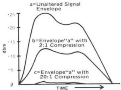
Fig. 4 - Attack & Release Times "track" the envelope of the input signal.
line
| IN (Rotation point) | OUT (1:1 Unity) | OUT (2:1') | OUT (4:1) | OUT (20:1) | | ------------------- | --------------- | ---------- | --------- | ---------- | | 0 | 0 | 0 | 0 | 0 | | +5 | ~5 | ~3 | ~2 | ~1 | | +10 | ~10 | ~6 | ~4 | ~2 | | +15 | ~15 | ~9 | ~6 | ~3 | | +20 | ~20 | ~12 | ~8 | ~4 | | +25 | ~25 | ~15 | ~10 | ~5 |Fig. 5 - Input and Output Levels at various compression ratios.
SPECIFICATIONS—160
| INPUT | TypeActual ImpedanceConnectorMaximum Level | Balanced (differential) transformerless.50K-ohms (25K-ohms when used in unbalanced mode, one side tied to ground).Jones-type barrier strip.+21dB (8.7V) |
| OUTPUT | TypeActual ImpedanceConnectorMax. Level Bridging(10K-ohm or greater Z)Matching(600-ohms)Output Level Adjust(Continuous)Protection | Single-ended, ground-compensated; suitable for driving balanced or unbalanced loads.25 ohms (typical); will drive low or high impedance loads.Jones-type barrier strip.+26dB (15.5V)+24dBm (12.3V) ± 20dB from unity gain point.FET circuits prevent power turn-on or turn-off transients from reaching the output. |
| DISTORTION* | 0.075% 2nd harmonic at infinite compression at +4dBm output0.5% 3rd harmonic typical at infinite compression ratio | |
| EQUIVALENT INPUT NOISE(Unweighted) | -78dBm, typical, (input shorted). | |
| ATTACK TIME** (Time to reduce signal by 63% of level change) | 15 milliseconds for 10dB level change above threshold. 5 milliseconds for 20dB level change above threshold. 3 milliseconds for 30dB level change. | |
| RELEASE RATE** | 120dB/second | |
| COMPRESSION RATIO | Continuously variable from 1:1 to 120:1 (infinity). | |
| THRESHOLD | Continuously variable from 10mV(-38dB) to 3V(+12dB). | |
| INDICATORS | One L.E.D. indicator turns “on” to show when the input level is below set threshold; another turns “on” when the input level is above threshold. A steady-state, sine-wave tone exactly at the threshold voltage causes both L.E.D.’s to remain dimly illuminated. | |
| METERING | RangeFunctionCalibration | 60dB (-40dB to +20dB)Switchable for input level, output level or gain change.Rear panel potentiometer sets “0dB” for any level from -10dB(250mV) to +10dB(2.5V). |
| POWER REQUIREMENTS | 117V AC, 50 or 60Hz. 8 watts maximum. | |
*The wideband distortion figures appear to suggest that 3rd-harmonic distortion is dominant. Thus, an unweighted T.H.D. (Total Harmonic Distortion) figure would be similar to the 3rd-harmonic value. However, the specific breakdown of distortion is more informative. 3rd-harmonic distortion in the 160 Series decreases linearly as the frequency rises: at 100Hz 3rd-harmonic distortion is 1/2 the value at 50Hz, etc.
**Attack and release rates automatically vary with rate of change of program level (attack and release rates "track" the signal envelope). Specifications are subject to change without notice.
| INPUT | TypeActual ImpedanceConnectorMaximum Level | Unbalanced25K-ohmsRCA pin jack (phono connector).+17dB (5.5V) |
| OUTPUT | TypeActual ImpedanceConnectorMax. Level Bridging(10K-ohm or greater Z)Matching(600-ohms)Output Level Adjust(Continuous) | Unbalanced100 ohms (typical); will drive low or high-Z loads.RCA pin jack+18dB (6.16V)+16dBm (4.9V)±20dB from unity gain point. |
| DISTORTION* | 0.75% 2nd harmonic at infinite compression at +4dBm output0.5% 3rd harmonic typical at infinite compression ratio | |
| EQUIVALENT INPUT NOISE(Unweighted) | -78dBm, typical, (input shorted). | |
| ATTACK TIME**(Time to reduce signal by 63% of level change) | 15 milliseconds for 10dB level change above threshold. 5 milliseconds for 20dB level change above threshold. 3 milliseconds for 30dB level change. | |
| RELEASE RATE** | 120dB/second | |
| COMPRESSION RATIO | Continuously variable from 1:1 to 120:1 (infinity). | |
| THRESHOLD | Continuously variable from 10mV(-38dB) to 3V(+12dB). | |
| INDICATORS | One L.E.D. indicator turns “on” to show when the input level is below set threshold; another turns “on” when the input level is above threshold. A steady-state, sine-wave tone exactly at the threshold voltage causes both L.E.D.’s to remain dimly illuminated. | |
| METERING | RangeFunctionCalibration | 60dB (-40dB to +20dB)Switchable for input level, output level or gain change.Rear panel potentiometer sets “0dB” for any level from -10dB(250mV) to +10dB(2.5V). |
| POWER REQUIREMENTS | 117V AC, 50 or 60Hz. 8 watts maximum. | |
*The wideband distortion figures appear to suggest that 3rd-harmonic distortion is dominant. Thus, an unweighted T.H.D. (Total Harmonic Distortion) figure would be similar to the 3rd-harmonic value. However, the specific breakdown of distortion is more informative. 3rd-harmonic distortion in the 160 Series decreases linearly as the frequency rises: at 100Hz 3rd-harmonic distortion is 1/2 the value at 50Hz, etc.
**Attack and release rates automatically vary with rate of change of program level (attack and release rates "track" the signal envelope). Specifications are subject to change without notice.
dbx PRODUCT WARRANTY
All dbx products are covered by a Limited Warranty. Consult your warranty card or local dealer for details.
FACTORY SERVICE
The dbx Customer Service Department is prepared to give additional assistance in the use of this product. All questions regarding interfacing dbx equipment with your system, service information or information on special applications will be answered. You may call during normal business hours – Telephone: 617-964-3210 or write to:
dbx, Inc.
71 Chapel Street
Newton, MA 02195
Attn: Customer Service Department
Should it become necessary to have your equipment factory serviced;
-
Please repack the unit including a note describing the problem along with the day, month and year of purchase.
-
Send the unit freight prepaid to:
dbx, Inc.
224 Calvary Street
Waltham, MA 02154
Attn: Repair Department
- We recommend that you insure the package and send it via United Parcel Service wherever possible.
- Please direct all inquiries to the dbx Customer Service Department.
Outside the United States — contact your nearest dbx dealer for the name of an authorized repair center.

Manufactured under one or more of the following U.S. patents: 3,681,618; 3,714,462; 3,789,143; 4,101,849; 4,097,767. Other patents pending.
SCHEMATIC dbx 161

Asperity Noise
This is a swishing type of background noise that occurs with tape recordings in the presence of strong low frequency signals, especially when there are no high frequency signals to mask the hiss. Asperity noise is caused by minute imperfections in the surface of the tape, including variations in the magnetic particle size in the tape's oxide coating. The imperfections increase or decrease the strength of the magnetic field passing the play head in a random manner, resulting in audible noise. Asperity noise may be present even when no program is recorded. When a program is recorded, asperity noise becomes superimposed on the signal, creating modulated asperity noise, or "modulation noise." Using high-quality tape with a calendered surface helps reduce asperity and modulation noise (calendered tape is pressed smooth by high-pressure rollers).
Attack Time
Attack time may mean different things, depending on the context. In music, the time it takes for a note to reach its full volume is the attack time of the note. Percussive instruments have short attack times (reach maximum volume quickly) and wind instruments have long attack times (reach maximum volume more gradually).
When a compressor (or expander) changes the level of an incoming signal, the circuitry actually requires a finite amount of time to complete that change. This time is known as the attack time. More precisely, the attack time is the interval (usually measured in milliseconds or microseconds) during which the compressing or expanding amplifier changes its gain from the initial value to 63% of the final value.
Aux Input (Aux Level)
Aux inputs, an abbreviation for auxiliary inputs, are low sensitivity jacks provided on most hi-fi and semi-professional equipment. Aux inputs (also known as "aux level" or "line level" inputs) have "flat" frequency response and are intended to be used with preamplified signals. Aux-level (line-level) signals are medium-level, higher than microphone levels, but not enough power to drive a speaker. The advantage to these levels is that they are less susceptible to hum and noise than are microphone levels. Typical items which might be connected to aux inputs are tape machine "play" outputs, tuner outputs, and dbx "play" outputs. Mic-level or phono-level signals are considerably lower in level than aux inputs (approx. -60 to -40dBV), so they will not produce adequate volume when connected to an aux input. Moreover, phono cartridge outputs require RIAA equalization which is not provided by aux inputs.
Bandwidth
Bandwidth refers to the "space" between two specific frequencies which are upper and lower limits; alternately, bandwidth refers to the absolute value of the range of frequencies between those limits. Thus, a filter which passes frequencies from 1,000Hz to 10,000Hz may be said to have a bandwidth of 1kHz-10kHz, or it may be said to have a 9kHz bandwidth (10kHz minus 1kHz equals 9kHz).
Bandwidth is not necessarily the same as frequency response. Bandwidth may be measured at low levels, and frequency response at higher levels. Moreover, bandwidth may refer only to certain portions of the circuitry within a piece of equipment, whereas frequency response may refer to the overall performance of the equipment. Thus, while the overall input-to-output frequency response of dbx type II equipment is 20Hz to 20kHz, the bandwidth of the RMS detection circuitry within that equipment is 30Hz to 10kHz.
Bass
The low audio frequency range below approximately 500Hz. For the purpose of discussion or analysis, the bass range may be further divided into upper bass (250 to 500Hz), mid bass (100-200Hz), low bass (50-100Hz), and ultra-low bass (20-50Hz).
Bass Boost
An accentuation of the lower audio frequencies (bass frequencies), whereby they are made louder than other frequencies.
Biamplified
Descriptive of a sound system which utilizes a low level cross-over network to divide the full-spectrum audio signal into low and high frequency ranges. These ranges are then fed to separate power amplifiers, which in turn feed low frequency speakers (woofers) and high frequency speakers (tweeters).
Bias
Bias, as the term is used in tape recording, is a very high frequency signal (usually over 100kHz) that is mixed with the program being recorded in order to achieve linear magnetization of the tape. If only the audio program were applied to the recording head, a very distorted recording would result because lower-energy portions of the program would not be able to overcome the initial magnetization threshold of the tape (known as hysteresis).
The frequency of the bias signal is not critical, so long as the record and erase bias are synchronized. However, the bias
energy level has a direct effect on the recorded level, background noise, and the distortion. It is sometimes necessary to reset the bias level for optimum performance with different types of recording tape, and professional tape machines are equipped with continuously variable bias controls; many consumer tape machines are now equipped with bias selector switches.
Clipping
Clipping is a very distorted sound. It occurs when the output capabilities of an amplifier are exceeded, and the amp can no longer produce any more voltage, regardless of how much additional gain or how much more input signal is present. Clipping is relatively easy to see on an oscilloscope, and it is sometimes audible as an increase in harmonic distortion. In severe cases of clipping (hard clipping), sine-waves begin to resemble square waves, and the sound quality is very poor. Often, the maximum output level of an amplifier is defined as that level where clipping begins to occur. There is a phenomenon known as input clipping, and this may occur where the input signal is so high in level that it exceeds the level-handling ability of the transformer and/or of the input amplifier. Clipping also occurs when tape is saturated by excessive record levels.
So-called "soft clipping" is usually the result of transformer saturation, and it may be somewhat less objectionable than the "hard clipping" that occurs when output voltage limits are reached. Aside from degrading the sound quality, clipping can damage loudspeakers. Output clipping may be avoided by reducing the level of the input signal, reducing the gain of the amplifier, or using a larger amplifier. Input clipping may be avoided by reducing the level of the incoming signal, and then increasing the gain of the amplifier.
Clipping Level
This is the signal level at which clipping just begins to occur. Clipping level is not always easy to define. It may be a matter of visually judging the waveform on an oscilloscope as the level is increased; alternately, clipping level may be defined as the level at which harmonic distortion reaches a given value. Tape clipping, or saturation, is defined as the 3% harmonic distortion level.
Compression
Compression is a process whereby the dynamic range of program material is reduced. In other words, the difference between the lowest and highest audio levels is "squeezed" into a smaller dynamic range. A compressed signal has higher average level, and therefore may have more apparent loudness than an uncompressed signal, even though the peaks are no higher in level. Compression is
achieved with a compressor, a special type of amplifier that decreases its gain as the level of the input signal increases. The amount of compression is expressed as a ratio of the input dynamic range to the output dynamic range; thus, a compressor that takes a program input with 100dB of dynamic range and yields an output program of 50dB dynamic range may be said to have a 2:1 compression ratio.
Compressor
A compressor is an amplifier that decreases its gain as the level of the input signal increases to reduce the dynamic range of the program (see "compression"). A compressor may operate over the entire range of input levels, or it may operate only on signals above and/or below a given level (the threshold level).
Crossover Frequency
In loudspeaker systems and multi-amplifier audio systems, the transition frequency (actually a frequency range) between bass and midrange or midrange and treble speakers or amplifiers.
Crossover Network
A circuit which divides the audio spectrum into two or more frequency bands for distribution to different speakers (high level crossover) or different amplifiers which then feed different speakers (low level crossover).
High level crossovers are usually built into the speaker cabinet, and are passive (they require no power supply). Low level crossovers are used in biamplified or triamplified sound systems. They are usually self-contained, and come before the power amplifiers. Low level crossovers may be passive or active; active low level crossovers are known as "electronic crossovers."
Damping Factor
The ratio of loudspeaker impedance to the amplifier's output source impedance. Damping describes the amplifier's ability to prevent unwanted, residual speaker movement. The higher the numerical value, the better the damping.
DB (Decibel) also, dBv dBV dB SPL dBm dB
One dB is the smallest change in loudness the average human ear can detect. 0dB SPL is the threshold of human hearing whereas the threshold of pain is between 120 and 130dB SPL. The term dB is an abbreviation for decibel, or 1/10 of a Bel. The decibel is a ratio, not an absolute number, and is used to express the difference between two power, voltage or sound pressure levels. (dB is 10 times the logarithm of a power ratio or 20 times the logarithm of a voltage
or sound pressure ratio,) if the number of "dB's" are referenced to a given level, then the value of the dB number becomes specific.
dBV expresses a voltage ratio. 0dBV is usually referenced to 1.0V RMS. Thus 0dBV=1V RMS, +6dBV=2V RMS, +20dBV=10V RMS, etc.
dB SPL expresses a Sound Pressure Level ratio. dB SPL is a measure of acoustic pressure (loudness), not acoustic power, which would be measured in acoustic watts. 0dB SPL is equal to 0.0002 dynes/square centimeter (the threshold of human hearing at 1kHz). As with dBV, an increase of 6dB SPL is twice the sound pressure, and an increase of 20dB SPL is an increase of 10 times the sound pressure.
dBm expresses a power ratio. 0dBm is 1 milliwatt (.001 watts), or 0.775V rms delivered to a 600-ohm load. +3 dBm=2 milliwatts, or 1.096V into 600 ohms ( 2 times 0dBm), +10dBm=10 milliwatts, or 2.449V into 600 ohms (3.16 times 0dBm), etc. dBV and dBm differ by 2.21 when dealing with 600-ohm circuits. However, when the impedance is other than 600 ohms, the value of dBV remains the same if the voltage is the same, whereas the value of dBm decreases with increasing impedance.
dB alone, without any suffix, doesn't mean anything unless it is associated with a reference. It may express the difference between two levels. Thus, the difference between 10dBV and 15dBV, the difference between 0dBm and 5dBm, and the difference between 90dB SPL and 95dB SPL are all differences of 5dB.
Decay Time
Decay time may mean different things, depending on the context. A compressor's decay time is also known as its release time or recovery time. After a compressor (or expander) changes its gain to accommodate an incoming signal, and the signal is then removed, the decay time is the amount of time required for the circuitry to return to "normal." More precisely, the decay time is the interval (usually measured in microseconds or milliseconds) during which the compressing or expanding amplifier returns to 90% of the normal gain. Very fast decay times can cause "pumping"
or "breathing" effects, whereas very slow decay times may cause moderate-level program which follows high-level program or program peaks to be too low in level.
Decoder
When a circuit restores an original program from a specially treated version of that program, the circuit may be said to decode the program. The equipment or circuit which performs this function is known as a decoder. Decoders must be used only with programs which have been encoded by complementary encoding circuitry. Typical decoders include: FM tuners that use multiplex decoders to extract left and right stereo signals from left-plus-right and left-minus-right signals, matrix quadraphonic decoders that extract four channels of program from the stereo program on encoded recordings, and dbx decoders that retrieve wide-dynamic range programs from the compressed programs on dbx-encoded recordings.
De-emphasis & Pre-emphasis
De-emphasis and pre-emphasis are related processes that are usually done to avoid audio noise in some storage or transmission medium. Pre-emphasis is a boost at specific higher frequencies, the encoding part of an encoding/decoding system. De-emphasis is an attenuation at the same frequencies, a reciprocal decoding that counteracts the pre-emphasis. In dbx noise reduction, de-emphasis is performed by the decoder (the play circuitry). The de-emphasis attenuates high frequencies, thereby reducing tape modulation noise and restoring the original frequency response of the program before it was dbx encoded. There are other types of pre-emphasis and de-emphasis. For example, in FM tuners, de-emphasis is used to compensate for special equalization (known as 75-microsecond pre-emphasis) applied at the station's transmitter.
Dynamic Range
The dynamic range of a program is the range of signal levels from the lowest to the highest level. In equipment, the dynamic range is the "space," in dB, between the residual noise level and the maximum undistorted signal level. A program with wide dynamic range has a large variation from the softest to the loudest passages, and will tend to be more lifelike than programs with narrow dynamic range.
Encoder
When a circuit processes an original program to create a specially treated version of that program, the circuit may be said
to encode the program. The equipment or circuit which performs this function is known as an encoder. Encoded programs must decoded only with complementary decoding circuitry. Typical encoded programs include: FM multiplex broadcasts, matrix quadraphonic recordings, and dbx encoded recordings.
Envelope
In music, the envelope of a note describes the change in average signal level from initial attack, to peak level, to decay time, to sustain, to release time. In other words, the envelope describes the level of the note as a function of time. Envelope does not refer to frequency.

The outline is the envelope, the signal is within the envelope.
In fact, any audio signal may be said to have an envelope. While all audio frequencies rise and fall in instantaneous level from 40 to 40,000 times per second, an envelope may take many milliseconds, seconds or even minutes to rise and fall. In dbx processing, the envelope is what "cues" the rms level detection circuitry to compress and expand the signal; the peak or average level of individual cycles of a note would be useless for level detection because the gain would change much too rapidly for audibly pleasing sound reproduction.
EQ (Equalization)
EQ or equalization, is an intentional change in the frequency response of a circuit. EQ may be used for boosting (increasing) or cutting (decreasing) the relative level of a portion of the audible spectrum. Some EQ is used for achieving sound to suit personal listening tastes, while other types of EQ are specifically designed to correct for non-linearities in the system; these corrective EQ "curves" include tape (NAB or CCIR) equalization, and phonograph (RIAA) equalization. In a sense, the pre-emphasis and de-emphasis used in dbx processing are special forms of equalization.
There are two common types of EQualization curves (characteristics): PEAKING and SHELVING. Shelving EQ is used in most Hi-Fi bass and treble tone controls. Peaking EQ is used in Hi-Fi midrange tone controls, in graphic equalizers, and many types of professional sound mixing equipment.
EQ is performed by an equalizer, which may be a specially built piece of equipment, or it may be no more than the tone control section of an amplifier. Graphic equalizers have many controls, each affecting one octave, one-half octave, or one-third octave of the audio spectrum. (An octave is the interval between a given tone and its repetition eight tones above or below on the musical scale; a note which is an octave higher than another note is twice the frequency of the first note.)
Expander
An expander is an amplifier that increases its gain as the level of the input signal increases, a characteristic that "stretches" the dynamic range of the program (see "expansion"). An expander may operate over the entire range of input levels, or it may operate only on signals above and/or below a given level (the threshold level).
Expansion
Expansion is a process whereby the dynamic range of program material is increased. In other words, the difference between the lowest and highest audio levels is "stretched" into a wider dynamic range. Expansion is sometimes used to restore dynamic range that has been lost through compression or limiting done in the original recording or broadcast; expansion is an integral part of commander-type noise reduction systems, including dbx. Expansion is achieved with an expander, a special type of amplifier that increases its gain as the level of the input signal increases. The amount of expansion is expressed as a ratio of the input dynamic range to the output dynamic range; thus, an expander that takes a program input with 50dB of dynamic range and yields an output program of 100dB dynamic range may be said to have a 1:2 compression ratio.
Fundamental
A musical note is usually comprised of a basic frequency, plus one or more whole-number multiples of that frequency. The basic frequency is known as the fundamental, and the multiples are known as harmonics or overtones. A pure tone would consist of only the fundamental.
Ground Compensated Output
This is a sophisticated output circuit that senses the potential difference between the ground of the dbx unit and the shield ground of unbalanced inputs to which the dbx unit is connected. Ideally, the dbx unit and the input of the following device should be at the same level (potential). However, where grounding is not "right" (where so-called "ground loops" exist), this circuit calculates the ground error and adds a correction signal to the high side of the output, thereby cancelling much of the hum, buzz and noise that might otherwise have been introduced by ground loops.
Harmonic Distortion
Harmonic distortion consists of signal components appearing at the output of an amplifier or other circuit that were not present in the input signal, and that are whole-number multiples (harmonics) of the input signal. For example, an amplifier given a pure sine-wave input at 100Hz may produce 200Hz, 300Hz, 400Hz, 500Hz, 600Hz and even 700Hz energy, plus 100Hz, at its output (these being the 2nd, 3rd, 4th, 5th, 6th and 7th order harmonics). Usually, only the first few harmonics are significant, and even-order harmonics (i.e. 2nd and 4th) are less objectionable than odd-order harmonics (i.e. 3rd and 5th); higher harmonics may be negligible in comparison to the fundamental (100Hz) output. Therefore, rather than specifying the level of each harmonic component, this distortion is usually expressed as T.H.D. or Total Harmonic Distortion. While T.H.D. is the total power of all harmonics generated by the circuitry, expressed as a percentage of the total output power, the "mixture" of different harmonics may vary in different equipment with the same T.H.D. rating.
Harmonics
Overtones which are integral multiples of the fundamental.
Headroom
Headroom refers to the "space," usually expressed in dB, between the nominal operating signal level and the maximum signal level. The input headroom of a circuit that is meant to accept nominal -10dB levels, but can accept up to +18dB without overdrive or excessive distortion, is 28dB (from -10 to +18 equals 28dB). Similarly, the output headroom of a circuit that is meant to supply nominal +4dBm drive levels, but that can produce +24dBm before clipping is 20dB. A circuit that lacks adequate headroom is more likely to distort by clipping transient peaks, since these peaks can be 10 to 20dB above nominal operating signal levels.
I.M. (Intermodulation Distortion)
Intermodulation distortion consists of signal components appearing at the output of an amplifier or other circuit that were not present in the input signal, that are not harmonically related to the input, and that are the result of interaction between two or more input frequencies. I.M. distortion, like harmonic distortion, is usually rated as a percentage of the total output power of the device. While some types of harmonic distortion are musical, and not particularly objectionable, most I.M. distortion is unpleasant to the ear.
Impulse Response
Related to the rise time of a circuit, the impulse response is a measurement of the ability of a circuit to respond to sharp sounds, such as percussion instruments or plucked strings. A circuit with good impulse response would tend to have good transient response.
Level Match
The dbx noise reduction system is unlike competitive systems in that there is no one threshold at which compression or expansion begins. Instead, compression occurs linearly, with respect to decibels, over the full dynamic range of the program. By necessity, there is an arbitrary signal level which passes through the encoder and decoder without being changed in level. This level is known as the level match point (transition point). Some dbx equipment provides for user adjustment of the level match point, for monitoring purposes only. Although this is not necessary for proper encode/decode performance, by setting the level match point to be approximately equal to the nominal (average) signal level, there will be no increase or decrease in level as you switch from monitoring "live" program to monitoring dbx-processed program.
Limiter
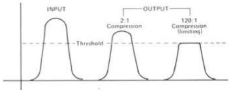
A limiter is a type of compressor, one with a 10:1 or greater compression ratio. A limiter with a high compression ratio (120:1) can be set so that no amount of increase in the input signal will be able to raise the output level beyond a preset value. The difference between limiting and compression is that compression gently "shrinks" dynamic range, whereas limiting is a way to place a fixed "ceiling" on maximum level, without changing the dynamic range of program below that "ceiling," or threshold.
Line Level (Line Input)
Line level refers to a preamplified audio signal, in contrast to mic level, which describes a lower-level audio signal. The actual signal levels vary. Generally, mic level is nominally -50dBm (with typical dynamic range of -64dBm to +10dBm). Line level signals vary, depending on the audio system. Hi-Fi line levels are nominally -15dBV, whereas professional line levels are nominally +4dBm or +8dBm (with typical dynamics ranging from -50dBm to +24dBm).
Line inputs are simply inputs that have sensitivities intended for line level (preamplified) signals. Often, the nominal impedance of a line level input will be different than the nominal impedance of a mic level input.
Modulation Noise
Modulation noise is a swishing type of background hiss that occurs with tape recordings in the presence of strong low frequency signals. The noise depends on the level of the recorded signal; the higher the recorded signal level, the higher the modulation noise. Modulation noise has typically been "masked," hidden by the dominant signal and/or by the background hiss of the tape. However, when the background hiss is removed, as with dbx processing, modulation noise could become audible. This would happen primarily with strong, low-frequency signals, but in fact it is minimized by dbx's pre-emphasis and de-emphasis.
Octave
In music or audio, an interval between two frequencies having a ratio of 2:1.
Overshoot
When a compressor or expander changes its gain in response to a fast increase or decrease in level, the maximum gain change should be directly proportional to the actual signal level. However, in some compressors the level detection and gain changing circuitry develop a kind of "inertia," over-reacting to changes in level, increasing or decreasing the gain more than the fixed ratio asked for. This over-reaction is known as overshoot, and it can cause audibly non-linear compression (distortion). dbx circuits have minimal overshoot, so they provide highly linear compression and expansion.
Peak Level
An audio signal continuously varies in level (strength, or maximum voltage) over any period of time, but at any instant, the level may be higher or lower than the average. The maximum instantaneous value reached by a signal is its peak level (see RMS level).
Phase Shift
"Time shift" is another way to describe phase shift. Some circuitry, such as record electronics and heads, will delay some frequencies of an audio program with respect to other portions of the same program. In other words, phase shift increases or decreases the delay time as the frequency increases. On an absolute basis, phase shift cannot be heard, but when two signals are compared to one another, one having a phase shift relative to the other, the effects can be very noticeable, and not very desirable. Excessive phase shift can give a tunnel-like quality to the sound. Phase shift also can degrade the performance of commander type noise
reduction systems which depend on peak or average level detection circuitry.
Power Amplifier
A unit that takes a medium-level signal (e.g., from a pre-amplifier) and amplifies it so it can drive a loudspeaker. Power amplifiers can operate into very low impedance loads (4-16 ohms), whereas preamplifiers operate only into low impedance (600 ohms) or high impedance (5,000 ohms or higher) loads. Also known as a main amplifier, the power amplifier may be built into an integrated amplifier or a receiver.
Preamplifier
A device which takes a small signal (e.g., from a microphone, record player), or a medium-level signal (e.g., from a tuner or tape recorder), and amplifies it or routes it so it can drive a power amplifier. Most preamplifiers incorporate tone and volume controls. A preamp may be a separate component, or part of an integrated amplifier or of a receiver.
Pre-Emphasis (See "de-emphasis")
Receiver
A single unit that combines tuner, preamp and power amplifier sections.
Release Time or Release Rate (See "decay time" and "attack time")
Rise Time (Attack Time)
This is the ability of a circuit to follow (or "track") a sudden increase in signal level. The shorter the rise time, the better the frequency response. Rise time is usually specified as the interval (in microseconds) required to respond to the leading edge of a square-wave input.
RMS Level
RMS level (Root Mean Square) is a measurement obtained by mathematically squaring all the instantaneous voltages along the waveform, adding the squared values together, and taking the square root of that number. For simple sine waves, the RMS value is approximately 0.707 times the peak value, but for complex audio signals, RMS value is more difficult to calculate. RMS level is similar to average level, although not identical (Average level is a slower measurement).
Sub Harmonic
A sub-multiple of the fundamental frequency. For example, a wave the frequency of which is half the fundamental frequency of another wave is called the second sub harmonic of that wave.
Sub Woofer
A loudspeaker made specifically to reproduce the lowest of audio frequencies, usually between 20Hz and 100Hz.
Synthesizer
An ELECTRONIC MUSIC SYNTHESIZER is an audio processor that has a built-in sound generator (oscillator), and that alters the envelope of the sound with voltage controlled circuitry. Synthesizers can produce familiar sounds and serve as musical instruments, or they can create many unique sounds and effects of their own.
A SUB HARMONIC SYNTHESIZER is a device which is not used to create music, but to enhance an existing audio program. In the case of the dbx Model 100, the unit creates a new signal that corresponds to the volume of the input signal, but is at 1/2 the frequency of the input signal.
Tape Saturation
There is a maximum amount of energy that can be recorded on any given type of magnetic tape. When a recorder "tries" to record more energy, the signals become distorted, but are not recorded at any higher levels. This phenomenon is called tape saturation because the magnetic oxide particles of the tape are literally saturated with energy and cannot accept any more magnetization.
T.H.D. (Total Harmonic Distortion) (See "Harmonic Distortion")
Threshold
Threshold is the level at which a compressor or limiter ceases to have linear gain, and begins to perform its gain-changing function (i.e., where the output level no longer rises and falls in direct proportion to the input level). In most systems, the threshold is a point above which the level changes, although there are compressors that raise signal levels below a threshold point. Some compander-type noise reduction systems, such as Dolby, ^® have upper and lower threshold between which the gain changes; these systems require careful level calibration for proper encode/decode performance, dbx noise reduction systems have no threshold at which compression or expansion factors change, so level calibration is not critical.
* 'Dolby' is a trademark of Dolby® Laboratories, Inc.
line
| Condition | Value | | ---------------------- | ----- | | 2:1 Compression | Peak | | 120:1 Compression (limiting) | Peak |Tracking Accuracy
Tracking refers to the ability of one circuit to "follow" the changes of another circuit. When two volume controls are adjusted in exactly the same way, the corresponding "sameness" of the output levels can be expressed as the tracking accuracy of the controls.
The level detection circuitry in a dbx encoder senses the signal level, changes the gain, and creates an encoded signal. The corresponding "sameness" of the original signal and the encoded/ decoded signal can be expressed as the tracking accuracy of the noise reduction system. (dbx systems are non-critical for the operator, and are built to close tolerances, so that tracking accuracy is excellent, even if the encoder and decoder are in different pieces of dbx equipment.)
Transition Level (See Level Match)
When a circuit has uniform compression or expansion throughout its full dynamic range, there must be some level which passes through the unit without being raised or lowered (where gain is unity). This unity gain level is the transition level or transition point. The transition point is a "window" 1dB wide, in a dbx encoder (compressor), all signals above the transition point are decreased in level, and all signals below the point are increased in level. Conversely, in a dbx decoder (expander), all signals above the transition point are increased in level, and all signals below the point are decreased in level. The transition level is similar to a "threshold," except it does not refer to a point at which compression or expansion factors change.
Triamplified
Similar to biamplified. A sound system where a passive cross-over network creates three frequency ranges, and feeds three power amplifiers: one for bass, one for mid, and one for high frequencies. The amplifiers are connected directly to the woofers, midrange drivers and tweeters without a passive, high-level crossover network.
Tuner
A unit which receives radio broadcasts and converts them into audio frequency signals. May be part of a receiver.
VCA (Voltage Controlled Amplifier)
Traditionally, amplifiers have been designed to increase signal levels (to provide gain). If an amplifier were required to decrease the level (to attenuate), it could become unstable, and might even oscillate. The gain (amount of amplification) in these traditional amplifiers would be adjusted by one of three methods (1) attenuating the audio signal fed to the input of the amplifier, (2) attenuating the audio output of the amplifier, or (3) changing the negative feedback (feeding more or less signal from the output back to the input, but in reversed polarity).
The VCA is a special type of amplifier that can be used to increase or decrease levels over a wide dynamic range. Instead of using signal attenuation or negative feedback, the gain (or loss) is adjusted by means of an external dc control voltage. dbx has a unique, patented VCA design that has extremely low noise and very wide dynamic range; the dbx VCA is the heart of dbx noise reduction equipment.
Woofer
A loudspeaker which reproduces only low frequencies.
- INDEX
- INTRODUCTION
- GENERAL INFORMATION
- Models
- Applications
- Stereo Tracking
- The Compressor/Limiter as a Tool
- INSTALLATION
- AC Power
- Signal Connections
- MODEL 161
- Input Impedance & Terminations
- Power Switch
- Threshold & Compression Ratio Adjustments
- INITIAL CONTROL SETTINGS
- PROCEDURE
- Output Gain Control Adjustment
- Meter Calibration & Use
- The 160 or 161 as a Line Amplifier
- A REVIEW
- Compressor
- Limiter
- Compression Ratio
- Threshold
- SPECIFICATIONS—160
- dbx PRODUCT WARRANTY
- FACTORY SERVICE
- Asperity Noise
- Attack Time
- Aux Input (Aux Level)
- Bandwidth
- Bass
- Bass Boost
- Biamplified
- Bias
- Clipping
- Clipping Level
- Compression
- Crossover Frequency
- Crossover Network
- Damping Factor
- DB (Decibel) also, dBv dBV dB SPL dBm dB
- Decay Time
- Decoder
- De-emphasis & Pre-emphasis
- Dynamic Range
- Encoder
- Envelope
- EQ (Equalization)
- Expander
- Expansion
- Fundamental
- Ground Compensated Output
- Harmonic Distortion
- Harmonics
- Headroom
- I.M. (Intermodulation Distortion)
- Impulse Response
- Level Match
- Line Level (Line Input)
- Modulation Noise
- Octave
- Overshoot
- Peak Level
- Phase Shift
- Power Amplifier
- Preamplifier
- Receiver
- Rise Time (Attack Time)
- RMS Level
- Sub Harmonic
- Sub Woofer
- Synthesizer
- Tape Saturation
- T.H.D. (Total Harmonic Distortion) (See "Harmonic Distortion")
- Tracking Accuracy
- Transition Level (See Level Match)
- Triamplified
- Tuner
- VCA (Voltage Controlled Amplifier)
- Woofer
Brand : DBX
Model : 161
Category : Audio Compressor