
PC189/9 - Air conditioner Foster - Free user manual and instructions
Find the device manual for free PC189/9 Foster in PDF.

| Product Type | Food Processor |
| Brand | Foster |
| Model | PC189/9 |
| Dimensions (H x W x D) | 35 x 25 x 30 cm |
| Weight | 5 kg |
| Power Consumption | 1200 W |
| Bowl Capacity | 2 L |
| Functions | Chopping, Blending, Grating, Slicing, Mixing |
| Speed Settings | 2 speeds plus pulse |
| Safety Features | Safety lock, overload protection, non-slip feet |
| Material | Stainless steel blade, plastic bowl |
| Dishwasher Safe Parts | Bowl, lid, blade, accessories |
| Maintenance | Wipe motor base with damp cloth; dry thoroughly |
| Spare Parts Available | Replacement bowl, blade, lid, pusher |
| Reparability | Spare parts accessible; service centers available |
| Energy Class | A |
| Cord Length | 1.2 m |
| Color | White/Black |
| Warranty | 2 years |
Frequently Asked Questions - PC189/9 Foster
User questions about PC189/9 Foster
0 question about this device. Answer the ones you know or ask your own.
Ask a new question about this device
Download the instructions for your Air conditioner in PDF format for free! Find your manual PC189/9 - Foster and take your electronic device back in hand. On this page are published all the documents necessary for the use of your device. PC189/9 by Foster.
USER MANUAL PC189/9 Foster
natural_image
Illustration of two industrial air conditioning units with ventilation grilles, no text or symbols presentIMPORTANT RECOMMENDATIONS
* The installation of this equipment should be entrusted to technicians approved by the vendor and in compliance with standards and rules in force.
* Before installing the unit ensure that the circulation and volume of air are sufficient to allow normal cooling of the condenser and compressor.
* Avoid installing the cabinet near major sources of heat or in direct sunlight.
* Note that too high ambient operating temperature can reduce performance.
* When connecting electrically earth continuity must be maintained between the unit and the supply socket.
* For cabinets supplied with a supply cable note that this is a specific part and should only be replaced with an original part. Being considered as a circuit-breaker, ensure that the plug is easily accessible as a means of electrical isolation.
* Protection against electrical overload or faults is the responsibility of the installer. Ensure that a circuit breaker or fuses are fitted in the supply circuit (See Name plate).
* All operations on the electrical or refrigeration circuits, including cleaning operations should only be undertaken with the unit DISCONNECTED (unplugged socket).
* The air-cooled compressor condenser must be cleaned regularly (every 3 to 6 months).
* The unit should not be sprayed or splashed with water:
- Do not use a jet wash on the exterior or technical parts of the unit.
- The equipment must not be installed in the open air or exposed to the elements.
* During any intervention it is imperative that the factory systems are respected so as not to compromise safety.
* The correct operation of this equipment depends on the safety and operating systems functioning as designed in the factory. We cannot be held responsible for poor operation that results from inappropriate modifications.
* The manufacturer can not be held responsible for usage other than that for which the equipment was designed.
TABLE OF CONTENTS
PAN CHILL
- Technical characteristics 2
1.1 Pan Chill 97/4 2
1.2 Pan Chill 140/6 3
1.3 Pan Chill 150/7 4
1.4 Pan Chill 189/9 5
-
Nameplate 6
-
Installation 6
3.1 General requirements 6
3.2 Handling 6
3.3 Unpacking and installation 6
3.4 Kit assemblies 7
3.5 Connections 12
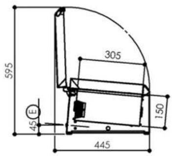
1. TECHNICAL CHARACTERISTICS
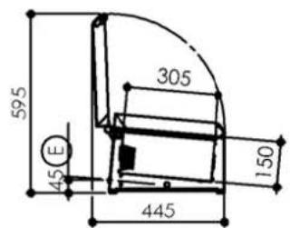
1.1 PC 97/4
| Dimensions (mm) | Length | Width | Height | |
| Outer - closed- open- glazing kit | 969 | 391,5445391,5 | 262595399 | |
| Liner | 688,5 | 305 | 150 | |
| Weight (Kg) | ||||
| Gross | 25 | |||
| Electricity | ||||
| Voltage 230V 1~ | ||||
| Frequency 50 Hz | ||||
| Protection | aM 2A | |||
| Maximum power 140 W | ||||
| Refrigeration | ||||
| Evaporator type | 345 at -10/+50°C | |||
| Compressor type | Hermetic | |||
| Refrigerant | Static | |||
| Heat emission | R290 | |||
| Refrigerant charge | (see nameplate) | |||
| Expansion | Capillary | |||
| Condensation | Air | |||
| Capacities | ||||
| Gross volume (L) | 30 | |||
| Capacity | 4 GN1/3 or multiple(not supplied) | |||
| Temperatures | ||||
| Max. ambient | +25°C | |||
| Temperature range | 0/+12°C | |||
| Construction | ||||
| Type | Monoblock type | |||
| Outer Finish | 5 sides stainless steel 304 | |||
| Liner Finish | Stainless steel 304 | |||
| Insulation | 35 mm thick polyurethane | |||
| Normes | ||||
| Safety : EN 60 335-1 | ||||
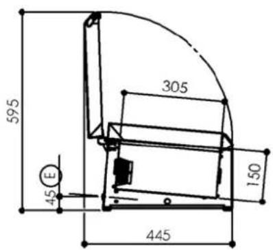
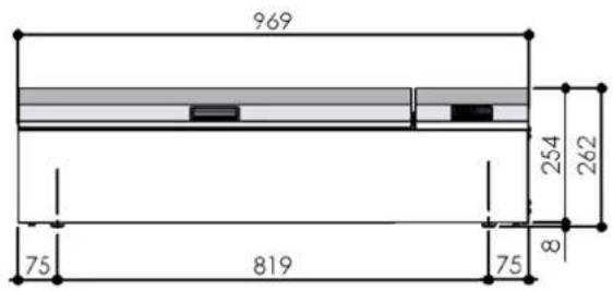
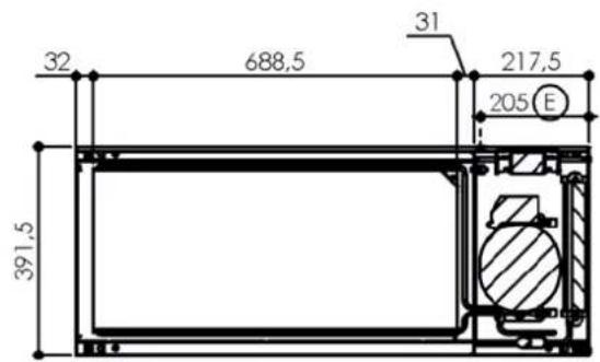
E : Output electric cable
Sound Level < 70 dBA
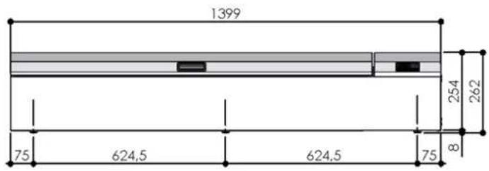
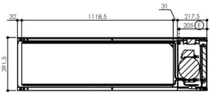
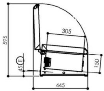
1.2 PC 140/6
| Dimensions (mm) | Length | Width | Height | |
| Outer - closed | 1399 | 391,5 | 262 | |
| - open | 445 | 595 | ||
| - glazing kit | 391,5 | 399 | ||
| Liner | 1118,5 | 305 | 150 | |
| Weight (Kg) | ||||
| Gross 27 | ||||
| Electricity | ||||
| Voltage 230V 1~ | ||||
| Frequency | 50 Hz | |||
| Protection | aM 2A | |||
| Maximum power 140 W | ||||
| Refrigeration | ||||
| Refrigerating power (W) | 345 at -10/+50°C | |||
| Compressor type | Hermetic | |||
| Evaporator type | Static | |||
| Refrigerant | R290 | |||
| Heat emission | 4306 W/24h | |||
| Refrigerant charge | (see nameplate) | |||
| Expansion | Capillary | |||
| Condensation | Air | |||
| Capacities | ||||
| Gross volume (L) | 50 | |||
| Capacity | 6 GN1/3 or multiple(not supplied) | |||
| Temperatures | ||||
| Max. ambient | +25°C | |||
| Temperature range | 0/+12°C | |||
| Construction | ||||
| Type | Monoblock type | |||
| Outer Finish | 5 sides stainless steel 304 | |||
| Liner Finish | Stainless steel 304 | |||
| Insulation | 35 mm thick polyurethane | |||
| Normes | ||||
| Safety : EN 60 335-1 | ||||
E: Sortie cable électrique
E : Output electric cable
Sound Level < 70 dBA
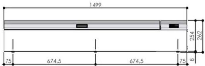
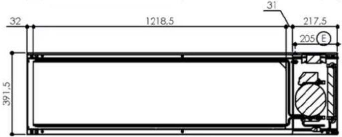
1.3 PC 150/7
| Dimensions (mm) | Length | Width | Height | |
| Outer - closed- open- glazing kit | 1499 | 391,5445391,5 | 262595399 | |
| Liner | 1218,5 | 305 | 150 | |
| Weight (Kg) | ||||
| Gross 28 | ||||
| Electricity | ||||
| Voltage 230V 1~ | ||||
| Frequency 50 Hz | ||||
| Protection | aM 2A | |||
| Maximum power | 140 W | |||
| Refrigeration | ||||
| Refrigerating power (W) | 345 at -10/+50°C | |||
| Compressor type | Hermetic | |||
| Evaporator type | Static | |||
| Refrigerant | R290 | |||
| Heat emission | 4306 W/24h | |||
| Refrigerant charge | (see nameplate) | |||
| Expansion | Capillary | |||
| Condensation | Air | |||
| Capacities | ||||
| Gross volume (L) | 55 | |||
| Capacity | 7 GN1/3 or multiple(not supplied) | |||
| Temperatures | ||||
| Max. ambient | +25°C | |||
| Temperature range | 0/+12°C | |||
| Construction | ||||
| Type | Monoblock type | |||
| Outer Finish | 5 sides stainless steel 304 | |||
| Liner Finish | Stainless steel 304 | |||
| Insulation | 35 mm thick polyurethane | |||
| Normes | ||||
| Safety : EN 60 335-1 | ||||
E : Output electric cable
Sound Level < 70 dBA
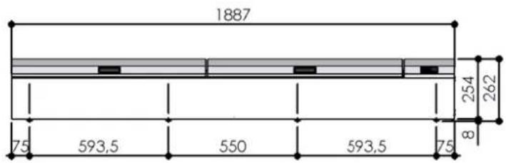
1.4 PC 189/9
| Dimensions (mm) | Length | Width | Height | |
| Outer - closed- open- glazing kit | 1887 | 391,5445391,5 | 262595399 | |
| Liner | 1606,5 | 305 | 150 | |
| Weight (Kg) | ||||
| Gross 30 | ||||
| Electricity | ||||
| Voltage 230V 1~ | ||||
| Frequency 50 Hz | ||||
| Protection | aM 2A | |||
| Maximum power | 140 W | |||
| Refrigeration | ||||
| Refrigerating power (W) | 345 at -10/+50°C | |||
| Compressor type | Hermetic | |||
| Evaporator type | Static | |||
| Refrigerant | R290 | |||
| Heat emission | 4306 W/24h | |||
| Refrigerant charge | (see nameplate) | |||
| Expansion | Capillary | |||
| Condensation | Air | |||
| Capacities | ||||
| Gross volume (L) | 75 | |||
| Capacity | 9 GN1/3 or multiple(not supplied) | |||
| Temperatures | ||||
| Max. ambient | +25°C | |||
| Temperature range | 0/+12°C | |||
| Construction | ||||
| Type | Monoblock type | |||
| Outer Finish | 5 sides stainless steel 304 | |||
| Liner Finish | Stainless steel 304 | |||
| Insulation | 35 mm thick polyurethane | |||
| Normes | ||||
| CE | Safety : EN 60 335-1 | |||
other
| Dimension | Value | | --------- | ----- | | Total Length | 1887 | | Upper Diameter | 254 | | Middle Diameter | 262 | | Lower Diameter | 8 | | Total Width | 75 | | Upper Width | 593.5 | | Middle Width | 550 | | Lower Width | 593.5 | | Total Height | 75 |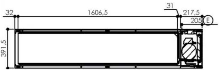
E : Output electric cable
Sound Level < 70 dBA
2. NAMEPLATE
The nameplate is to be found fixed on the back of the appliance.
For all correspondence relating to your equipment remember:
- The unit code (Type)
- The serial number (N° SERIE)
- The date (Date)
The main characteristics are reported on a label fixed to :
- The left hand internal panel
3. INSTALLATION
3.1 GENERAL REQUIREMENT
The installation, any repairs or alterations to this equipment should be undertaken by qualified specialists according to good practice.
3.2 HANDLING
The unit should be moved with adapted lifting gear.
If the unit has to be transported this should be done on its original pallet.
If moving the appliance without its pallet, it must be carried and not pulled.
The appliance must be stacked in horizontal position so that the arrows printed on the packaging are pointing upwards (the top of the device)
3.3 UNPACKING AND INSTALATION
3.3.1 UNPACKING
When unpacking, make sure that the unit is permanently in a horizontal position.
3.3.2 INSTALLATION
Once a location has been chosen ensure that the air around the unit is sufficient to provide adequate cooling to the condenser and compressor.
Allow a 5 to 10cm clearance between the walls and the cabinet.
Avoid proximity to any heat source.
3.4 KIT ASSEMBLIES
3.4.1 NIGHT COVER KIT
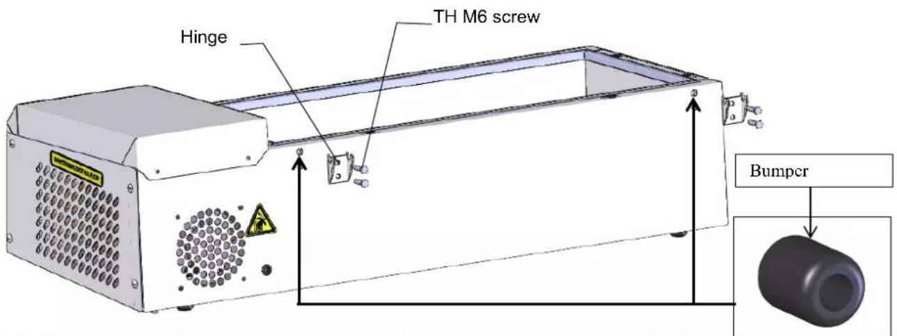
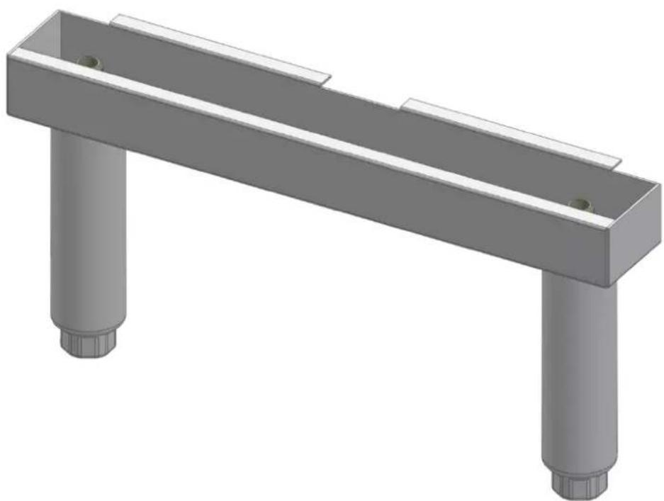
Fix the hinges on to appliance with TH M6 screws and galvanised L6N washers.
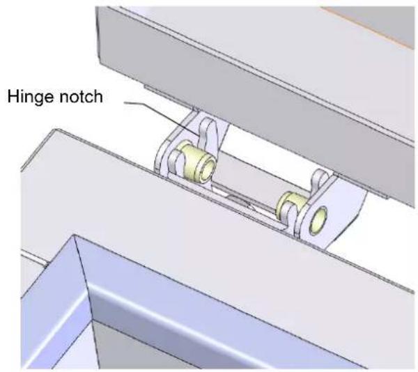
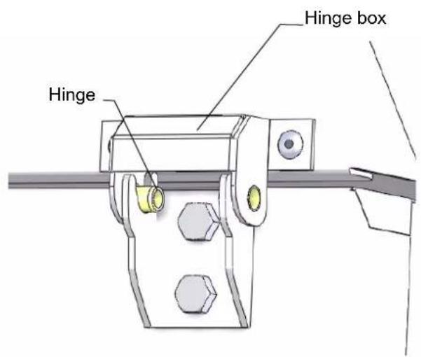
Simply click the cover on the appliance by placing the pivots (installed on the hinge boxes of the hood) into the hinge notches.
3.4.2 BRAKETS
Find a place or install the device while ensuring that nothing clutter the layout of it.
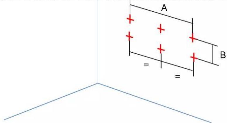
Trace on the wall 4 fixing positions taking account of the position of the height of the appliance (distance B between the two fixations of a wall = 131mm). For versions PC 189 and PC 221, there will be 3 brackets, so 6 fixing positions (3rd bracket is in the middle distance equivalent to two others).
Côte A :
PC 97 = 918mm
PC 140 = 1348mm
PC 150 = 1448mm
PC 189 = 1836mm
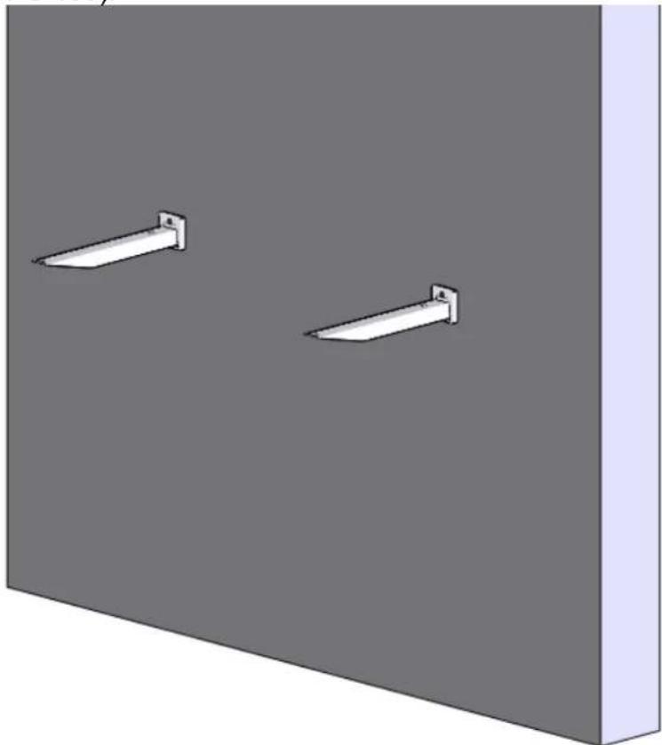
On these plots, drill holes in order to introduce dowels attachments adapted to the wall (screws and dowels, recommended M10 are not supplied with the kit) and then screw 2 wall fixings (or 3 version PC 189).
natural_image
3D rendering of two white wall-mounted sensors mounted on a gray panel against a dark background (no text or symbols)Then the fixing supports can be assembled on wall fixings.
Place the unit on the fixing supports and fix it with the TH M6 screws and L6N washers.
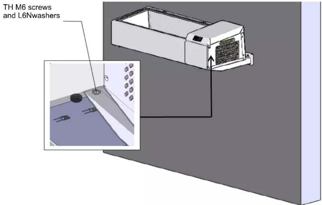
3.4.3 LEG'S SUPPORT
Fix 2 legs on 2 leg's support. (rigth leg's support and left leg's support)
natural_image
3D rendering of a mechanical support base with two cylindrical legs and a central horizontal beam (no text or symbols)The right leg's support has a shorter folding and the left leg's support has an extra notch.
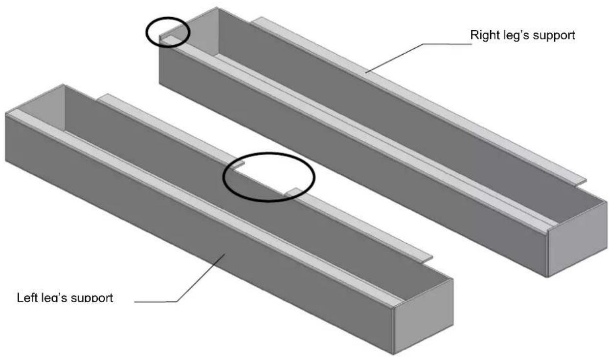
Fix the leg's supports in the device.
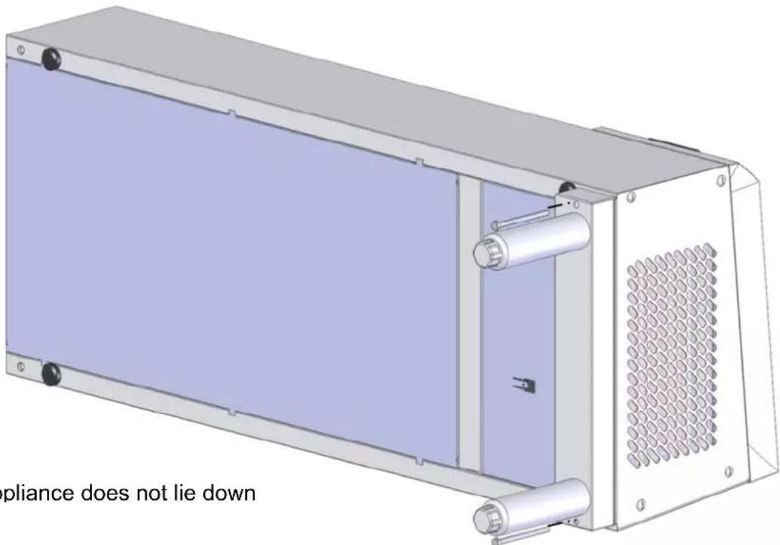
Nota:
The appliance does not lie down
With the shorter folding of right leg's support we can it install under the device without to being hindered by the lower folding of the right side.
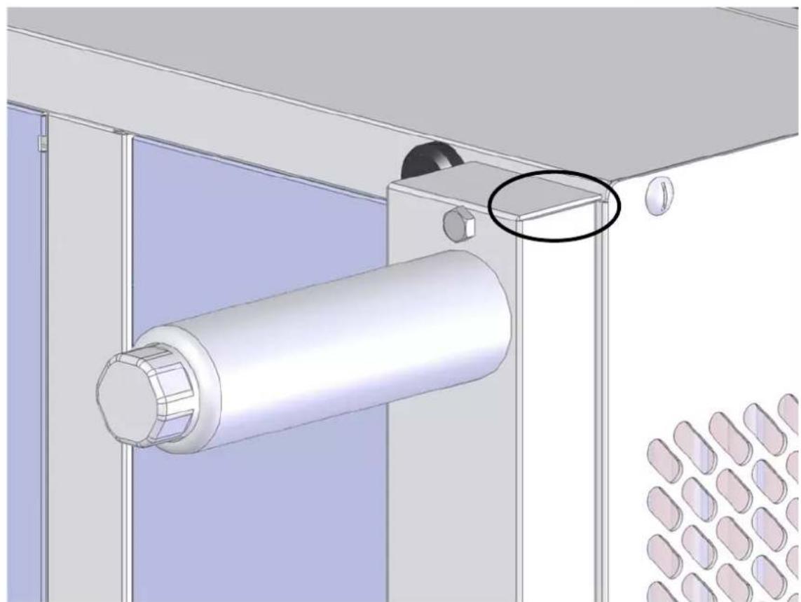
natural_image
3D mechanical assembly diagram showing a cylindrical component mounted on a panel, with a magnified inset highlighting a specific part (no text or symbols present)3.5 CONNECTIONS (SEE § 1 "Technical characteristics")
3.5.1 ELECTRICS
The unit is fitted with a supply cable which must not be removed.
EARTH continuity must be maintained (see § Important recommendations).
Provision of a circuit breaker or fuses to protect the supply is the responsibility of the installer.
USER MANUAL
PAN CHILL
FOSTER
PC 97/4
PC 140/6
PC 150/7
PC 189/9
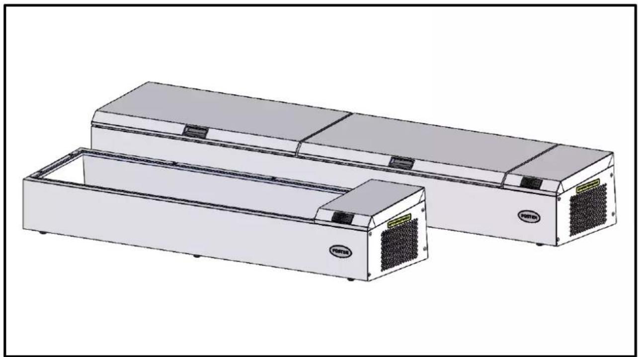
natural_image
Illustration of two industrial air conditioning units with ventilation grilles and a label 'PORTER' on one (no text or symbols on the devices themselves)IMPORTANT RECOMMENDATIONS
* This cabinet is designed for use in restaurants, catering facilities, etc... It is not intended for industrial use.
* It should be installed by a specialised installer.
* Avoid installing the cabinet near a major source of heat or in direct exposure to sunlight.
* Note that too high ambient temperature can impair performance.
* The air condenser must be cleaned regularly (every 3 to 6 months) by a refrigeration engineer.
* Do not modify the electrical connection made by the installer, particularly the earth continuity circuit. In case of a problem on the electric circuit, only the installer or the builder are competent for servicing
* The supply cable that is fitted is a specific part and should only be replaced with an original part. Being considered as a circuit-breaker, make sure that the plug is easily accessible as a means of isolation.
* Observe the rules of hygiene by regularly cleaning the :
. interior fittings
. interior lining
Do not use corrosive or acid products.
* Water spraying can cause damage.
. Do not clean with a water jet in order to avoid spraying the appliance.
. Do not install the appliance in the open air or exposed to the elements.
* Correct functioning depends on the factory fitted safety systems being respected. No responsibility can be accepted for malfunctions that result from modifications made to the equipment.
* The manufacturer can not be held responsible if the equipment is used for anything other than the purpose it was designed for.
ALL SPECIFICATIONS AND CHARACTERISTICS IN THIS MANUAL MAY BE SUBJECT TO CHANGE WITHOUT NOTICE.
TABLE OF CONTENTS
PAN CHILL
- Control panel 2
1.1 Description of the control panel 2
1.2 Utilisation of the controller 2
- Utilisation 4
2.1 General requirements 4
2.2 Loading 4
2.3 Temperature alarm 7
- Cleaning 7
3.1 Liner cavity 7
3.2 Surface in stainless steel 7
3.3 Regular cleaning 7
- Maintenance 8
4.1 Foreword relating to stainless steel 8
4.2 The commonest cases of corrosion 9
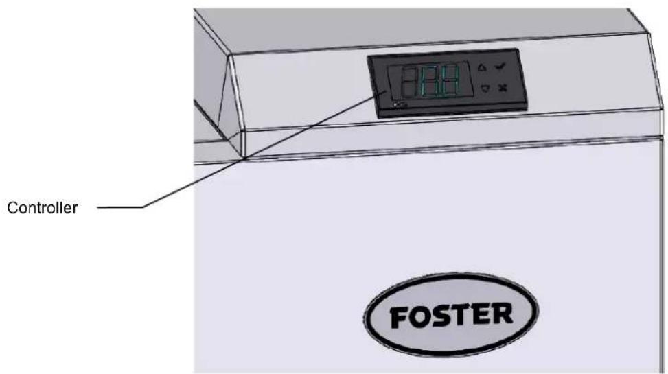
1. CONTROL PANEL
IMPORTANT
If the unit is not going to be used for a prolonged period, unplug or turn off at the isolator to protect the refrigeration equipment.
In standby mode the controller does not cut off general supply to the appliance and, as a consequence, only the compressor and condenser are switched off.
1.1 DESCRIPTION OF THE CONTROL PANEL
1.2 CONTROLLER USING
CD5 MODE D'EMPLOI
DESCRIPTION
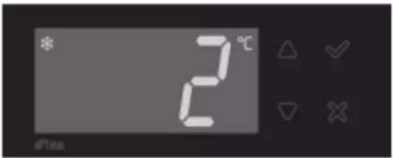

Increase
Validate


Decrease
Cancel

OPERATION
DISPLAY
During normal operation, the display shows either the temperature measured or one of the following indications:
| OFF | Controller in stand-by | HC | High temperature condenser |
| DEF | Defrost in progress | ALR | Digital input alarm |
| DO | Door open alarm | E1 | Probe T1 failure |
| HI | Room high temperature alarm | E2 | Probe T2 failure |
| LO | Room low temperature alarm | E3 | Probe T3 failure |
INFO MENU
The information available in this menu is:
| T1 | Instant probe 1 temperature | LOC | Keypad state lock |
| T2 | Instant probe 2 temperature | PSD | Password |
| T3 | Instant probe 3 temperature |
SETTING
| Setpoint: display and modification | Standby (SB=YES) | Light ON/OFF |
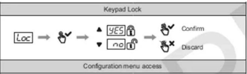
flowchart
graph LR
    A["Loc"] --> B{Yes}
    B --> C{No}
    C --> D["Confirm"]
    C --> E["Discard"]
DEFROST START
2. UTILISATION
2.1 GENERAL REQUIREMENTS
When starting or if the unit has been out of use for some time, the full start up procedure should be followed
Loading should not take place until the set temperature adjusted by the controller has been obtained.
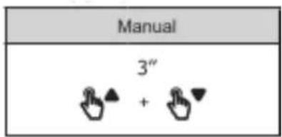
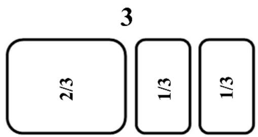
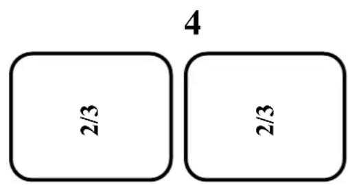
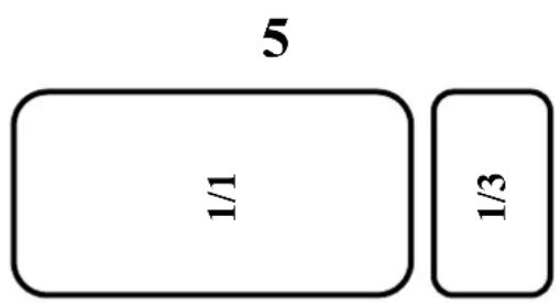
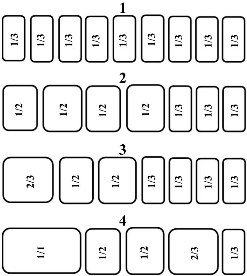
2.2 LOADING
It is imperative to set all stainless steel pans (and trough compensation when necessary on 1400 GN 1/3 and 1800 GN 1/3 versions) in the unit for correct operation.
examples some combinations of stainless steel pans assembly.
2.2.1 97/4
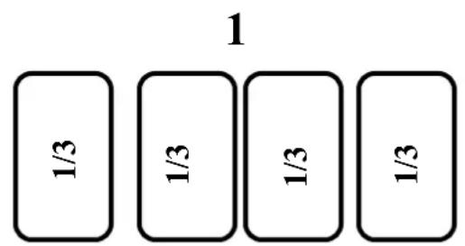
2.2.2 140/6
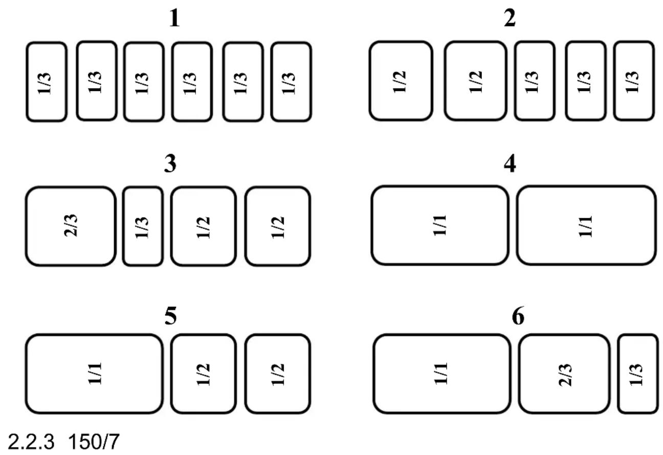
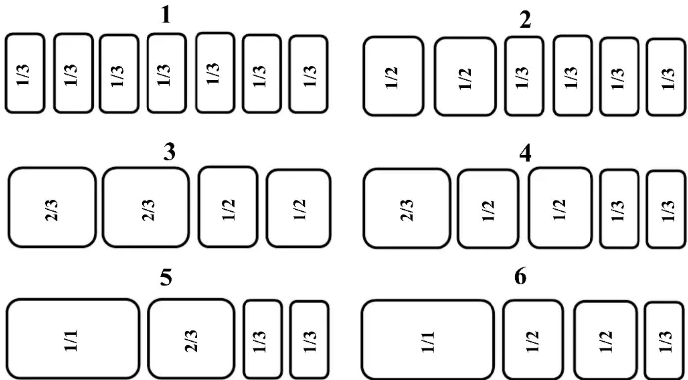
2.2.4 189/9
2.3 TEMPERATURE ALARM
A high limit alarm is factory set at +10°C with an exclusion period of 120 min.
In specific cases these settings can be changed to suit different requirements by the installing engineers (see Installation Manual).
3. CLEANING
WARNING
Before all cleaning operations the unit should be SWITCHED OFF.
- THE USE OF CLEANING PRODUCTS AT A TEMPERATURE OF OVER 60°C IS STRICTLY PROHIBITED.
- Using a high pressure jet or lance is also prohibited on external and technical parts of the equipment.
◆ The interior cavity may be jet washed.
◆ The warranty will not cover problems that result from failure to heed the above warnings.
3.1 LINER CAVITY
All traces of dirt should be eliminated on a daily basis.
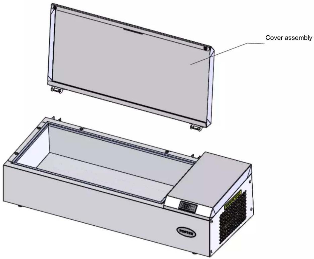
Particularly clean glazing and cover kit with a wet wipe in order to remove particles that may be inserted in folds and corners.
Being just put the kit cover can be removed for easy cleaning.
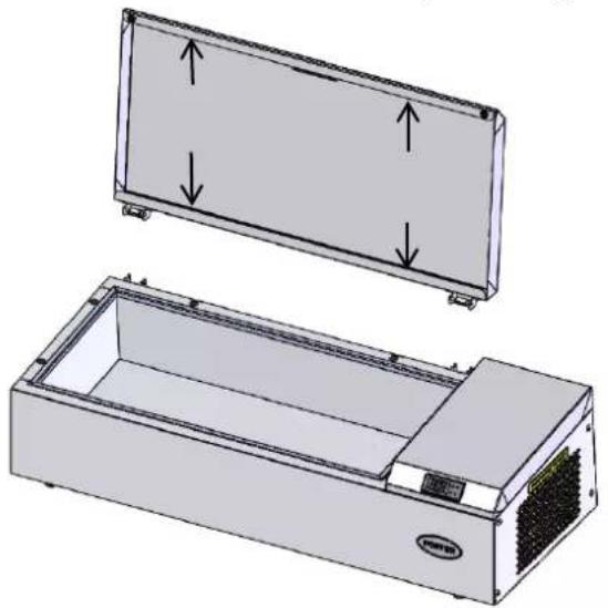
natural_image
Technical illustration of a rectangular electronic device with internal components and mounting holes, showing two views of the lid (top: front, side) and a smaller internal casing (bottom: top).3.2 STAINLESS STEEL SURFACES
Wash these surfaces with soap and water or a neutral nonabrasive detergent. RINSE THOROUGHLY and dry
Do not use abrasive products, plastic or steel wool pads: these will scratch the surface.
Never rub stainless steel with steel wool but only Scotch Brite pad or similar product when this is absolutely necessary and only in the same direction as the grain of the polish.
3.3 REGULAR CLEANING
In order to maintain refrigeration performance and ensure the longevity of the compressor, cleaning is required to clear dust from the condenser every 3 to 6 months. This should only be undertaken by the installation engineer.
4. MAINTENANCE
4.1 FOREWORD RELATING TO STAINLESS STEELS
Stainless steel is a type of steel designed to allow a thin protective layer to form on the metal surface to protect it against corrosion (Oxide film resulting from the chemical reaction of oxygen on the metal surface).
Any element disturbing the formation of this film or making its partial destruction easier (Food deposits, spills, stagnant liquids...) all degrade the resistance to corrosion.
Just because the composition of stainless steel allows it to resist some chemical aggression better than ordinary steel, do not imagine that stainless steel is indestructible.
3 main factors of corrosion to watch for:
- The chemical environment
In general :
* Diverse brines (Concentrations of salt, sauerkrauts...)
* Chlorides, particularly in: - Cleaning products - Bleach.
- Temperature:
Any chemical environment becomes considerably more aggressive towards stainless steel at higher temperatures.
- Time: The longer the contact time the more perceptible the consequences of the corrosion will be.
The combination of these three factors can lead to the destruction of interior surfaces even those of high quality stainless steel.
It should be noted that when stainless steel corrodes it is extremely rare that the corrosion comes from the steel itself. Generally inappropriate or badly used cleaning products, poor maintenance or extreme conditions of use are found to be the cause of the problems encountered.
WARNING
The manufacturer can not be held responsible for cases of corrosion encountered in such conditions and no warranty will then apply.
A list of the most common causes follows, to help you identify them and maintain your equipment service life for as long as possible.
4.2 THE COMMONEST CASES OF CORROSION
Floor cleaning
Cleaning floor tiles (after building work or during normal service) is often carried out with very aggressive products. If such products are sprayed under pressure without caution, the splashes beneath appliances cause corrosion of bases and panels.
Even worse the vapours from these products fall onto the equipment and extend the corrosion to all surfaces unless the area is immediately and forcefully ventilated.
Inappropriate cleaning products (Bleach, acids, soda)
If such products or any others that are not specifically designed for use on stainless steel are used an irreversible attack occurs on the stainless steel surface.
Cleaning products applied at too high a temperature
All cleaning products become more aggressive if applied hot or to a hot surface. As a general rule the temperature should not exceed 60 °C , so as not to attack the stainless steel and provoke irreversible blackening of the surface...
Cleaning products not rinsed off properly
If interior surfaces once cleaned are not thoroughly rinsed in order to eliminate any trace of cleaning product this residue will in time continue its action and provoke corrosion.
Even worse if such surfaces are heated to over 60^ C with such products still on them the problems mentioned already will inevitably occur.
Stagnation of cleaning products
In the same way any area that can retain cleaning chemicals notably gulleys, drains ...must be rinsed thoroughly and abundantly. (Use a nylon brush and fresh water to strengthen the rinsing action).
Salt concentration
Salt found in every kitchen is often the cause of pitting in stainless steel. Any spillage should be cleaned off immediately.
Use in an intensive brined environment
Certain products such as Sauerkraut (acidity) and seafood (presence of salt), and as a general rule all brines require particular attention. Occasional use should not present problems provided everything is carefully and systematically cleaned after every operation.
High chlorination levels in water
At times certain water supplies have too high a chlorine content. In such cases it is not rare to encounter the problems mentioned above.
Cleaning aluminium or aluminium coated accessories
The presence of aluminium-coated sheet in a chlorinated solution considerably increases the level of attack on stainless steel.
Do not leave aluminium accessories such as trays in the bottom of cabinets. One night is sufficient to attack the equipment's surface at the points of contact.
- IMPORTANT RECOMMENDATIONS
- TABLE OF CONTENTS
- PAN CHILL
- TECHNICAL CHARACTERISTICS
- PC 97/4
- PC 150/7
- PC 189/9
- NAMEPLATE
- INSTALLATION
- GENERAL REQUIREMENT
- HANDLING
- UNPACKING AND INSTALATION
- UNPACKING
- INSTALLATION
- KIT ASSEMBLIES
- NIGHT COVER KIT
- BRAKETS
- LEG'S SUPPORT
- CONNECTIONS (SEE § 1 "Technical characteristics")
- ELECTRICS
- USER MANUAL
- FOSTER
- CONTROL PANEL
- IMPORTANT
- DESCRIPTION OF THE CONTROL PANEL
- CONTROLLER USING
- CD5 MODE D'EMPLOI
- DESCRIPTION
- OPERATION
- DISPLAY
- INFO MENU
- SETTING
- DEFROST START
- UTILISATION
- GENERAL REQUIREMENTS
- LOADING
- 97/4
- 140/6
- 189/9
- TEMPERATURE ALARM
- CLEANING
- WARNING
- LINER CAVITY
- STAINLESS STEEL SURFACES
- REGULAR CLEANING
- MAINTENANCE
- FOREWORD RELATING TO STAINLESS STEELS
- THE COMMONEST CASES OF CORROSION
- Floor cleaning
- Inappropriate cleaning products (Bleach, acids, soda)
- Cleaning products applied at too high a temperature
- Cleaning products not rinsed off properly
- Stagnation of cleaning products
- Salt concentration
- Use in an intensive brined environment
- High chlorination levels in water
- Cleaning aluminium or aluminium coated accessories
Brand : Foster
Model : PC189/9
Category : Air conditioner