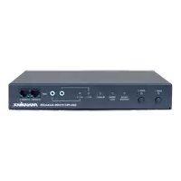
SM3-PRO - Multiprise avec gestion d'alimentation Panamax - Free user manual and instructions
Find the device manual for free SM3-PRO Panamax in PDF.


| Product Type | Power Management with Remote Cloud-based Control and Monitoring |
| Brand | Panamax |
| Model | SM3-PRO |
| AC Operating Voltage | 120 Vac |
| Current Capacity | 15 A |
| UL 1449 Voltage Protection Rating | 330V L-N, 400V L-G, 400V N-G |
| Nominal Discharge Current | 3 kA |
| Energy Dissipation | 1,575 Joules |
| Overvoltage Shutoff | 134 Vac |
| Undervoltage Shutoff | 95 Vac |
| EMI/RFI Noise Filtration | -18.7 dB @ 10 kHz, -50.5 dB @ 100 kHz, -43.9 dB @ 1 MHz |
| Number of Outlets | 3 (Rear Panel, 2 Switchable Banks: Bank 1: 1 outlet, Bank 2: 2 outlets) |
| Remote Control | BlueBOLT® Cloud-based Control and Monitoring |
| Automatic Voltage Monitoring (AVM) | Yes – Disconnects equipment during unsafe voltage conditions |
| Protect-or-Disconnect Circuitry | Yes – Disconnects AC power during catastrophic surges |
| Ethernet Switch | 2-Port 10/100 BaseT |
| Accessory Ports | 2 Mini-plug ports for 5VDC sensors (e.g., ELAN SENSE) |
| Circuit Breaker | Resettable 15A |
| Power Cord | Detachable 2 ft. (IEC 320-C13 with retention clip) |
| Mounting | Universal Mounting Bracket Included |
| Safety Features | Wiring Fault Indicator, Unsafe Voltage Indicator, BlueBOLT Indicator |
| Sequential Startup/Shutdown | Programmable delays for each outlet bank (via BlueBOLT or UDP) |
| Warranty | 3-Year Limited Product Warranty; Connected Equipment Policy up to $5,000,000 |
Frequently Asked Questions - SM3-PRO Panamax
User questions about SM3-PRO Panamax
0 question about this device. Answer the ones you know or ask your own.
Ask a new question about this device
Download the instructions for your Multiprise avec gestion d'alimentation in PDF format for free! Find your manual SM3-PRO - Panamax and take your electronic device back in hand. On this page are published all the documents necessary for the use of your device. SM3-PRO by Panamax.
USER MANUAL SM3-PRO Panamax
Power Management with Remote Cloud-based Control and Monitoring.
• 15 Amp Capacity
• 3 Rear Panel Outlets in 2 Controllable and Monitored banks
- Fully Programmable
• BlueBOLTED
• AVM & Protect-or-Disconnect Circuitry
• 2-Port 10/100 Ethernet Switch
• Linear Filtration,-18.7dB@10kHz, -50.5dB@100kHz, -43.9dB@1MHz
- Accessory Inputs for External Sensors
- Rear Panel Circuit Breaker
• Universal Mounting Bracket Included
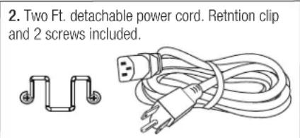
• Detachable 2 ft. Power Cord
Important: You will need the SM3-PRO's unique MAC Address and Challenge Key (provided on the 2 labels attached to the cover of the Quick Start Guide which is included in the SM3-PRO packaging). One label is permanently adhered to the Quick Start Guide and the other is removable for your convenience.
Introduction
Congratulations for purchasing the Panamax SM3-PRO Power Management with remote, cloud based control and monitoring. The SM3-PRO features Panamax's revolutionary AVM (Automatic Voltage Monitoring) circuit, and our exclusive Linear Filtering Technology (LiFT). Together, these technologies comprise precisely what our customers have come to expect from Panamax: uncompromised AC protection and purification.
Outlets: Rear panel outlets are controlled in two power filtered banks. They are grouped into two (2) switched banks. BlueBOLT® is included, providing secure, hosted IP system control and monitoring for the SM3-PRO.
Table of Contents
Feature Descriptions.... pg. 1
Important Safety Instructions, Front Panel Features Overview.... pg. 2
Rear Panel Features Overview, Bubble of Protection.... pg. 3
BlueBOLT® Setup, Registration, Trouble Shooting.... pg. 4
Outlet Sequencing and SM3-PRO Specifications....pg. 5
Diagram to Identify Connected Equipment, Additional Notes....pg. 6
Advanced Operation, Communication and Messaging Protocol ......pgs. 7-13
FCC Notice, Contacting Customer Service....pg. 13
Limited Product Warranty and Connected Equipment Policy.... pg. 14
Before You Begin Inspect Upon Receipt.
Box should contain the following, including the Quick Start Guide:


PANAMAX®
BlueBOLT®:
Remote Power Management technology provides secure, hosted IP (Internet Protocol) system control. With BlueBOLT™, custom electronics installers, integrators and end-users can remotely monitor and control power to home theater equipment by accessing power management components from anywhere in the world. From simple system reboots to comprehensive monitoring of power status, BlueBOLT™ provides the power to control complex A/V systems from their most fundamental level: their power source SM3-PRO).
LiFT Technology EMI/RFI Noise Filtration :
Your audio/video components are constantly being bombarded by electromagnetic interference (EMI) and radio frequency interference (RFI) through their AC power source. This contaminated power can affect audio/video equipment and will degrade the overall performance of your entire system. Common symptoms of contaminated power include loss of picture detail, dull colors, pops, hisses, hums and visual artifacts.
Protect-or-Disconnect:
In the event of a catastrophic power surge, such as a direct lightning hit, the Panamax unit will disconnect AC power to connected equipment.
Automatic Over & Under Voltage Protection (AVM):
Panamax's patented power monitoring circuitry constantly monitors the AC line voltage for unsafe voltage conditions such as momentary spikes or prolonged over-voltages and under-voltages (brownouts). These unsafe conditions pose a very dangerous threat to all electronic equipment within the home. If the SM3-PRO senses an unsafe power condition, it will automatically disconnect your equipment from the power to protect equipment from damage. Once the voltage returns to a safe level, the SM3-PRO will automatically reconnect the power.
- When subjected to a 6,000V (open circuit voltage) / 3,000A (short circuit current) surge, the SM3-PRO limits its voltage output to less than 330V peak, UL's lowest rating.
- If the magnitude of the surge is greater than the capacity of the surge protection components, the SM3-PRO's Protect or Disconnect Circuitry will disconnect your equipment in order to protect it. The SM3-PRO will need to be repaired or replaced by Panamax if this occurs within the product's 3 year warranty.
Sequential Startup/Shutdown:
Audio/video systems and networking systems often function best when powered up and down in a sequential manner. In an A/V system, components can be powered up and given a few moments to stabilize before an amplifier or powered subwoofer is turned on, avoiding annoying and potentially dangerous speaker "thumps" that can occur when all components are turned on simultaneously, or when amplifiers or subwoofers are turned on prior to other equipment. Networking systems also benefit from sequential turn on as often a modem will need time to boot up prior to turning on a router, switch or other downstream components. The SM3-PRO provides the ability to set turn on delays, turn off delays, and power cycle delays for each bank in the BlueBOLT® or via UDP command.
Accessory Port for Sensors:
The SM3-PRO includes two accessory ports for 5VDC sensors. These sensors allow outlet banks to be triggered on or off based on a variety of environmental conditions. Sensors are set up and indicated in the BlueBOLT® interface.
The accessory ports are compatible with the following ELAN™ SENSE sensors:
• AUDSENSOR Audio Sensor
• VIDSENSOR Video Sensor
• CTSENSOR Contact Closure Sensor
• VTSENSOR Voltage Sensor
• LTSENSOR Light/LED Sensor
• CRSENSOR Current/Magnetic Field Sensor
Ethernet Switch
A two-port Ethernet switch is provided for connecting an additional Ethernet-connected device without having to run a second LAN cable to the location.
Mounting
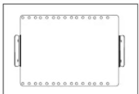
Mounting Bracket is provided for a variety of installation configurations. Mount bracket to desired location and snap SM3-PRO into the bracket. The SM3-PRO is held in place by two spring buttons located on each side of unit.
natural_image
Simple line drawing of a rectangular frame with rounded corners and two side connectors (no text or symbols)- Install Mounting Bracket
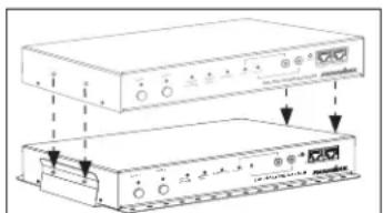
- Snap SM3-PRO into Mounting Bracket.
Important Safety Instructions
- Read these instructions.
- Keep these instructions.
- Heed all warnings. 4. Follow all instructions.
- WARNING: Do not use this apparatus near water. To reduce the risk of fire or electric shock, do not expose this apparatus to rain or moisture.
- Clean only with dry cloth.
- Do not install near any heat sources such as radiators, heat registers, stoves, or other apparatuses that produce heat.
-
Do not defeat the safety purpose of the polarized or grounding type plug. A polarized plug has two blades, with one wider than the other. A grounding type plug has two blades and a third grounding prong. The wide blade or the third prong is provided for your safety. If the provided plug does not fit into your outlet, consult an electrician for replacement of the obsolete outlet.
-
Protect the power cord from being walked on or pinched, particularly at plugs, convenience receptacles, and the point where they exit from the apparatus.
- Only use attachments/accessories specified by the manufacturer.
- Refer all servicing to qualified service personnel. Servicing is required when the apparatus has been damaged in any way, such as power-supply cord or plug is damaged, liquid has been spilled or objects have fallen into the apparatus, the apparatus has been exposed to rain or moisture, does not operate normally, or has been dropped.
- Where the power cord is used as the main disconnect device, the disconnect device shall remain readily accessible.
- This device must be connected to a main socket outlet with a protective earthing connection.
Front Panel Features Overview

1. Outlet Bank 1 and 2 Buttons
The blue light above each outlet bank button indicates its present ON/OFF state. Pressing the button for less than 5 seconds toggles the corresponding Outlet Bank's ON/OFF state. Pressing the button for 5 seconds or more initiates a reboot sequence for the corresponding Outlet Bank.
2. Unsafe Voltage Indicator
If the line voltage is less than 95 Vac or greater than 134 Vac, the outlets will shut off and this light will flash red. When the line voltage comes back to the safe operating range, an outlet turn-on sequence is initiated 5 seconds later.
3. Wiring Fault Indicator
Illuminates red if the outlet wiring is reverse-wired or the ground is not connected.
| Color/State | Status |
| OFF | The wall-outlet is properly wired |
| RED | The wall outlet is reversed-wired or the ground is not connected |
- BlueBOLT Indicator
| Color | Status |
| OFF Not connected to an active local area network (LAN) | |
| Blue Connected to an active LAN and is connected to the BlueBOLT server/cloud | |
5. Accessory 1 and 2 Status LEDs
Indicates accessory port activity/status
6. Two Mini-plug Accessory Ports
Interface to accessory modules to extend the functionality of the unit. 1/8" stereo phone jacks. Provides power (5VDC/400mA) and half-duplex serial communication to accessory modules.
7. Reset Button
Communication connectors reset / restore.
8. Ethernet 1 and 2 Connectors / 2-Port 10/100 BaseT Switch
Connect one port to an active local area network.
Connect the other port to an Ethernet-connected device (optional).
Link LED: Illuminated - Green when connected to an active LAN.
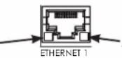
- Activity LED: Flashes to indicate that LAN connection is active.

Outlets: The three rear panel outlets are grouped into two switched outlet banks. (Outlets within an outlet bank are controlled together).
- Bank 1 has one outlet.
-
Bank 2 has two outlets.
-
Resettable 15A Circuit Breaker
- Power Inlet: 120 Vac / 15A, IEC 320-C13 with plug/cord retention clip.
- Ground Lug: connect to Panamax MOD-series signal protection module grounding busses with 14AWG (<12" length) wire to expand the signal protection capabilities.
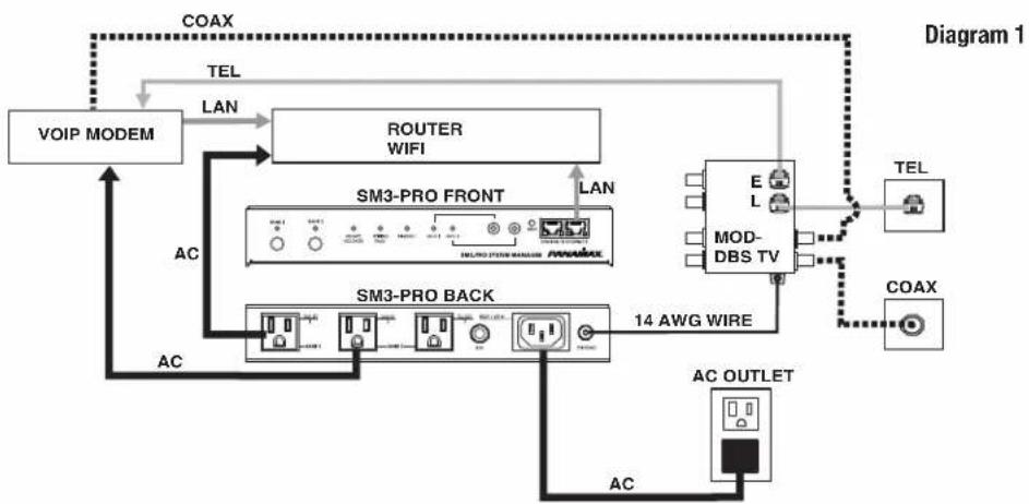
Typical Application Diagrams for Proper Connections
Sample setups to indicate the basic configuration for proper connections. Protecting all AC and signal lines will keep your system safe and ensure compliance with Panamax's Connected Equipment Policy.
flowchart
graph TD
    A["VOIP MODEM"] -->|LAN| B["ROUTER WIFI"]
    B -->|LAN| C["SM3-PRO FRONT"]
    C -->|LAN| D["MOD-DBS TV"]
    D --> E["TEL"]
    D --> F["COAX"]
    C --> G["SM3-PRO BACK"]
    G --> H["14 AWG WIRE"]
    H --> I["AC OUTLET"]
    I --> J["AC"]
    J --> K["AC"]
    K --> A
    style A fill:#f9f,stroke:#333
    style B fill:#ccf,stroke:#333
    style C fill:#cfc,stroke:#333
    style D fill:#fcc,stroke:#333
    style E fill:#cff,stroke:#333
    style F fill:#ffc,stroke:#333
    style G fill:#cfc,stroke:#333
    style H fill:#fcc,stroke:#333
    style I fill:#ffc,stroke:#333
    style J fill:#cfc,stroke:#333
    style K fill:#fcc,stroke:#333

flowchart
graph TD
    A["DISPLAY"] -->|HDMI| B["SAT"]
    A -->|HDMI| C["MEDIA PLAYER"]
    C -->|LAN| D["SM3-PRO FRONT"]
    D -->|LAN| E["LAN"]
    D --> F["SM3-PRO BACK"]
    F --> G["AC OUTLET"]
    G --> H["TEL"]
    G --> I["COAX"]
    H --> J["14 AWG WIRE"]
    I --> J
    J --> K["MOD-DBSTV"]
    K --> L["TEL"]
    K --> M["COAX"]
    style A fill:#f9f,stroke:#333
    style B fill:#ccf,stroke:#333
    style C fill:#ccf,stroke:#333
    style D fill:#cfc,stroke:#333
    style F fill:#cfc,stroke:#333
    style G fill:#cfc,stroke:#333
    style H fill:#cfc,stroke:#333
    style I fill:#cfc,stroke:#333
    style K fill:#fcc,stroke:#333
    style L fill:#fcc,stroke:#333
Note: You will need the SM3-PRO's unique MAC ADDRESS and CHALLENGE KEY (duplicate labels provided in packaging on cover of Quick Start Guide as well as on the underside of the unit itself) in order to register the BlueBOLT® device.
SYSTEM SETUP
Step 1. Connect Ethernet cable from router/modem to BlueBOLT input on SM3-PRO.
Step 2. Plug in SM3-PRO.
Step 3. Wait for the BlueBOLT light to turn on.

BlueBOLT® Online Registration
Note: Make sure to complete system setup before registering.
Step 1. Log into http://www.mybluebolt.com for online registration.
Your BlueBOLT® enabled SM3-PRO Power Management Component is completely plug-and-play and does not require any software installation or network configuration (including configuring of network ports). The online BlueBOLT® control interface is operated through your web browser.
Step 2. Using any Internet connected computer go to www.mybluebolt.com in your standard Internet browser. Please make sure your browser is up to date with the latest software for best BlueBOLT interface performance.
Step 3. Follow the on screen instructions to create an account and/or take control of your BlueBOLT enabled product.
Once you input the MAC ADDRESS and included CHALLENGE KEY, if BlueBOLT™ cannot detect your device (please allow up to 60 seconds), please follow the on-screen troubleshooting guide. Also confirm an Internet connection by accessing a general website – example www.panamax.com.
Troubleshooting
Q. Is your Power Management Component receiving power?
A. Check the power cable and confirm the unit's breaker has not been tripped.
Q. Is your Internet connection functioning?
Q. Can you access a general web page?
Q. Is your SM3-PRO connected to your internet router or modem?
A. Check the Ethernet cable and confirm that the unit is connected to an active Internet connection, and make sure those connected devices are receiving power.
If you have answered "Yes" to all of these questions and are still unable to connect your SM3-PRO component, please contact Panamax customer service at 1-800-472-5555.
POWER CYCLE AND OUTLET SEQUENCING
The outlet banks of the SM3-PRO are configured to turn on and off in a programmed sequence where each outlet bank has a set of programmed delay times.
The delay times are pre-programmed but may be changed on the BlueBOLT web site or by issuing the
| Outlet Bank | Power Cycle | Delay | Turn On Delay | Turn Off | Delay | |
| 1 | 5 | seconds | 0 | seconds | ||
| 2 | 10 | seconds | 0 seconds | 10 seconds |
Power Cycle Delay: When a Power Cycle is initiated, the outlet bank will immediately turn off and then turn back on after the Power Cycle Delay time
Turn On Delay: When a Turn On Sequence is initiated, the outlet bank will turn ON after the Turn On Delay time.
Turn Off Delay: When a Turn Off Sequence is initiated, the outlet bank will turn OFF after the Turn Off Delay time.
SM3-PRO Specifications
| AC POWER | ||||||||
| Operating Voltage | 120 | Vac | ||||||
| Current Capacity | 15 | A | ||||||
| UL 1449 Voltage Protection Rating | 330V L-N, 400V L-G, 400V N-G | |||||||
| UL | 1449 | Nominal | Discharge | Current | 3 | |||
| Initial | Clamping | Level | 200V | |||||
| Energy | Dissipation | 1,575 | Joules | |||||
| Overvoltage | shutoff | 134 | Vac | ± | ||||
| Undervoltage | shutoff | 95 | Vac | ± | ||||
| EMI | / | RFI | Noise | Filtration | -1 | |||
| -50.5dB | @ | 100kHz | ||||||
| -43.9dB | @ | 1MHz | ||||||
Specifications subject to change due to product upgrades and improvements.
Identify Connected Equipment
Use this diagram to write in what pieces of equipment are plugged into each outlet for an easy reference.

flowchart
graph TD
    subgraph LAN 1
        A["OUTLE 1"] --> B["SANK 1"]
        C["OUTLE 2"] --> D["SANK 2"]
        E["OUTLE 3"] --> F["TA"]
        G["CROCK NO"] --> H["PO Box"]
    end
    subgraph LAN 2
        I["PO Box"] --> J["SME PRO SYSTEM MANAGER"]
        K["PO Box"] --> L["STRESS - IR EPERT 2"]
    end
    subgraph Outlet 1
        M["OUTLE 2"] --> N["PO Box"]
        O["OUTLE 3"] --> P["PO Box"]
    end
    subgraph Outlet 2
        Q["PO Box"]
        R["PO Box"]
    end
    subgraph Outlet 3
        S["PO Box"]
    end
Additional Notes:
Name / Location of Installation
MAC ADDRESS ____ ____ ____ ____ ____ ____
CHALLENGE KEY ____ - ____ - ____
Phone Number(s)
SM3-PRO provides a built-in HTTP (web page server at default port 80) which can be accessed via a typical "web page browser" allowing the user to configure the network settings.
• DHCP or static IP address assignment
- IP address
- Subnet mask
- Gateway Address
• DNS server Address 1
On start-up, SM3-PRO will use two IP addresses on its Ethernet connection:
- A random link-local address can be discovered by link-local utilities such as the Bonjour zero-configuration networking utility by Apple.
- A local network address, either statically assigned, or from DHCP. If the address was assigned by DHCP it can be discovered by inspection of your router's connected devices table.
In addition to providing external access and control via Panamax/Furman's hosted BlueBOLT platform, SM3-PRO may also be interfaced to control and automation systems on the local area network. Command, information and event messages are provided in standard XML format over UDP port 57010.
GENERAL
All messages are encapsulated in standard XML format. As per XML standard, It is required that the XML version declaration be included at the start of each message. Messages that do not conform to the standard will be ignored. In addition to the XML version declaration, every message must also specify the type of device (model) and its unique MAC ID (mac) in its root element using the
<?xml version="1.0"?><device class="sm3" id="1065a3040000">...</device>
This would be considered the "envelope" for all messages, where the "..." is to be considered the content of the message.
There are three types of messages: event messages, information messages and command messages.
Event messages are sent in response to a change of device status or settings. It should be noted that events are not sent in reply to a query.
Command messages are set to the SM3-PRO to query information, change settings or initiate an action.
Information messages are sent from SM3-PRO in response to a query command.
In messages that contain timestamps, the timestamp will be expressed in standard UNIX time. UNIX time is expressed with up to a 10 decimal digit characters that represents the number of seconds that have passed since January 1st 1970 GMT.
Examples of the message format are provided in the table below.
| Example Event Message | Example Command Message | Example Information Message |
| Event message for outlet bank 2 switched ON | Command to switch outlet bank 2 OFF | Snippet of the response toquery |
The following sections document the possible message content and it should be assumed that the contents are always enclosed by the “envelope” and that the “envelope” text will not be repeated, unless needed for clarity.
Action and Queries
Command messages are sent to the SM3-PRO to have it perform a task. The task can be to perform a physical action such as switching an outlet bank and is referred to as an action. When the task is to transmit data such as device status it is referred to as a query. Whether the task is an action or query, the message is classified as a command.
If the command is for an action such as switching an outlet bank, the SM3-PRO will not necessarily provide a response message. If it is desired to receive an acknowledgement of receiving the command, the optional "xid" attribute may be included in the
<?xml version="1.0"?><device class="sm3" id="1065a3040000">
<command xid="123"><outlet id="1">0</outlet></command></device>
Is received by the SM3-PRO, it will perform the action (switch outlet bank 1 off) and respond with
<?xml version="1.0"?><device class="sm3" id="1065a3040000"><ack xid="123"></device>
General Query Element Structure
All query command messages are contained within a
For example, the query
<?xml version="1.0"?><device class="sm3" id="1065a3040000">
    <command><sendinfo></command></device>
Results in the following response:
<?xml version="1.0"?><device class="sm3" id="1065a3040000">
    <info time="1403729752">
    <sernum>12345678</sernum>
    <fwver>1.0</fwver>
    <bootcodever>1.0</bootcodever>
    <ipaddr>3194548209</ipaddr>
    </info></device>
</info>
Send Information Query
The Send Information query is used to retrieve the following system-level information from the SM3-PRO. Information elements are enclosed in the
Query
Response
| Time stamp of the data, provided in UNIX time | |
| Serial number | |
| firmware version | |
| boot loader firmware version | |
| ipaddress IP address, provided as a 32-bit (base-10) decimal value |
Send Status Query
The Send Status query is used to retrieve the following outlet status and electrical measurement information from the SM3-PRO-PRO. Status elements are enclosed in the
Query
Response
| stamp of the data, provided in UNIX time | |
| line voltage, 1 Vac precision | |
| voltage pkvolts, occurred at time “t”. | |
| amps Measured load current on outlet bank “bank”, 0.1 Ampere precision | |
| watts Measured power consumption on outlet bank “bank”, 1 Watt precision | |
| voltamps Measured volt-ampere consumption on outlet bank “bank”, 1 VA precision | |
| powerfactor Measured load power factor on outlet bank “bank”, 0.01 precision | |
| outlet sequencing status: 0 = no sequence, 1 = sequencing ON, 2 = sequencing OFF | |
| Power Condition: 0 = normal, 1 = fault recovery, 2 = under voltage, 3 = over voltage | |
| wiringfault Outlet wiring fault: 0 = no fault, 1 = reverse wiring or open ground fault | |
| Accessory port “port” input usage: 0 = no signal cable connected, accyportconnected 1 = signal cable connected | |
| accyportstate Accessory port “port” input status: 0 = sensor condition not sensed; 1 = sensor condition sensed | |
| state On/Off state for outlet bank “bank”; 0 = outlet bank OFF, 1 = outlet bank ON | |
| For Core Brands use only |
Send Settings Query
The Send Settings query is used to retrieve the device settings from the SM3-PRO such as outlet bank delays & trigger enable and display brightness level. Settings elements are enclosed in the
Query
Response
| Time stamp of the data, provided in UNIX time time="timestamp"... | ||
| Delay for outlet bank "bank" act="action"> delay time, in seconds | Action: 0 = turn off delay, 1 = turn on delay, 2 = power cycle delay |
General Command Element Structure
Command messages are contained within a
Sample command to switch outlet bank 2 OFF, the first with no acknowledgement, the second with acknowledgement:
| Command | Response |
| ... | |
Switch Outlet Bank
Command an outlet bank to turn ON or turn OFF
| Command | Control an outlet bank | |
| Attribute: id = “bank” | Which outlet bank to control | |
| Content 0 | 1 | 0 = turn outlet bank OFF | 1 = turn outlet bank ON |
| Example: | 0 | Turn OFF outlet bank 2 |
Cycle Outlet Bank
Command an outlet bank to turn OFF, wait for its power cycle delay time and then turn back ON.
| Command | Power cycle an outlet bank | |
| Attribute: id = “bank” | Which outlet bank to control | |
| Content | None | |
| Example: | Power cycle outlet bank 1 |
Power Sequence
Command the SM3-PRO to initiate a power on/off sequence. For a turn on sequence, the outlet banks will turn on after their turn on delay time. For a turn off sequence, the outlet banks will turn off after their turn off delay time.
| Command | Power sequence | |||||
| Attribute: | None | |||||
| Content 0 | 1 | 0 = Initiate power OFF sequence | 1 = Initiate power ON sequence | ||||
| Example: | 1 Initiate a power ON sequence | |||||
Reboot
Command the SM3-PRO to reboot all of its systems, equivalent to pulling the plug and plugging it back into an electrical outlet. Upon reboot, all outlets will turn off; outlets are restored to their on/off state prior to reboot; network connection is restored; connection to BlueBOLT is reestablished
| Command | Reboot SM | |
| Attribute: | None | |
| Content | None | |
| Example: |
Set Settings
This command is used to change one of more of the SM3-PRO configuration settings. All settings within the
Set Outlet Bank Delays
| Command | Set delay settings for an outlet bank | |
| Attribute: id="bank" act= 0 | 1 |2 Action: 0=OFF delay, 1=ON delay, 2=Power cycle delay | ||
| Content delay | Delay time, in seconds, 65536 seconds max | |
Set Settings Example:
| ... | |
| 10 | Set bank 1 for 10 second turn off delay |
| 1 | Set bank 1 for 1 second turn on delay |
| 30 | Set bank 1 for 30 second power cycle delay |
| 1 | Set bank 2 for 1 second turn off delay |
| ... |
EVENTS
Event messages are sent autonomously from SM3-PRO when some change occurs within the device – they are not replies to a query.
Subscribing to Event Messages
After start-up, SM3-PRO will not send any event messages. To receive event messages a command to "subscribe" to events must be sent.
The event subscription command is enclosed within the XML declaration and
...<commands><eventmgr><subscribe uri="ctrlsys://IPADDR:PORT"/></eventmgr></commands>...
IPADDR is the IP address and port number where the event messages should be sent. It may be a different IP address than the control system which sent the request.
PORT is the UDP port number.
Only one IP address / port event subscription is allowed.
For example, to have event messages sent from a SM3-PRO with MAC address 10-65-A3-03-FF-FF to a control system at IP address 192.168.0.127 listening on port 1726:
<?xml version="1.0"?><device class="sm3" id="1065a304ffff"><command><eventmgr><subscribe uri="ctrlsys://192.168.0.127:1726"/></eventmgr></command></device>
The unsubscribe command follows the same format
...<commands><eventmgr><unsubscribe uri="ctrlsys://IPADDR:PORT"/></eventmgr></commands>...
General Event Element Structure
All event messages are contained within an
A subscriber ID, "subsid" is assigned to each event subscription and is included in every event message sent to the subscriber.
A sample event message for outlet bank 2 switching ON:
...<event time="1234567890" evtid="123" subsid="1"><outlet id="2">1</outlet></event></device>
Event messages will be repeated until an acknowledgement message is sent back to SM3-PRO, or after a timeout period of approximately 20 minutes. The acknowledgement message syntax is:
...<command><eventmgr><ack evtid="123" subsid="1"></eventmgr></command></device>
Event Messages:
Outlet State Change
An Outlet State Change event is posted when any of the outlet banks turn ON->OFF or OFF->ON.
| Element | Tag: | |
| Attribute: | id = "bank" "bank" is the affected outlet bank number | |
| Content | 0 | 1 0 = outlet bank is OFF | |
| 1 = outlet bank is ON | ||
| Example: | 0 Outlet bank 1 is OFF | |
Sequence Status
A Sequence Status event is posted when a power on or power off sequence is initiated or completed.
| Element Tag: | ||||||||
| Attribute: | None | |||||||
| Content 0 | 1 | 2 0 = sequence done/finished/complete | 1 | = | turn | on | sequence | |||
| 2 | = | turn | off | sequence | ||||
| Example: | 0</seq> | Sequence has completed | ||||||
initiate initiate
Power Condition
A Power Condition event is posted when the unit enters or recovers from over-voltage or under-voltage shutdown mode.
| Element Tag: | |||||
| Attribute: | None | ||||
| Content 0 | 1 | 2 | 3 | 0 = power normal | ||||
| 1 = | fault | recovery | |||
| 2 = | under | voltage | |||
| 3 = | over | voltage | |||
| Example: | 3 Overvoltage condition | ||||
Wiring Fault
A Wiring Fault event is posted when a change to the outlet wiring condition is detected.
| Element | Tag: | |
| Attribute: | None | |
| Content | 0 | 1 0 = no wiring fault detected | 1 = wiring fault detected |
| Example: | 1 Wiring fault detected | |
Accessory Port Jack Sensed
An Accessory Port Jack Sensed event is posted when a connector is inserted into or removed from an accessory port input jack.
| Element Tag: | |||||||
| Attribute: | "id" | Accessory port number | |||||
| Content 0 | 1 0 = Connector was disconnected | 1 = Connector was connected | ||||||
| Example: Sensed that a connector was plugged into accessory port 1 id="1">1 | |||||||
Accessory Port Status
An Accessory Port Status event is posted when the connected sensor sense condition changes.
| Element | Tag: | |||||
| Attribute: | "id" | Accessory | port | number | ||
| Content | 0 | 1 0 = Condition sensed ON->OFF | 1 = | Condition | sensed | OFF->ON | |
| Example: | 1 Accessory port 2 sense condition OFF->ON | |||||
Settings Changed
A Settings Changed event is posted when the device settings such as outlet bank delays, outlet bank trigger enable and display brightness is changed. Information for all settings is transmitted, not just for the individual settings that changed.
| Element Tag: | ||
| Attribute: | None | |
| Content... | See Settings Event section for details | |
| Example:<delay id="1" act="2">12 | <set>Outlet bank 1-power cycle delay=12 sec</set> | |
Scheduled Action Fired
A Scheduled Action Fired event is posted when the M4000-PRO performs a scheduled operation.
| Element Tag: | ||
| Attribute: | None | |
| ContentSee the Outlet Command section for detailsaction | Scheduled days. See below. | |
| Elapsed minutes since midnight | ||
| Example:11550550550550550550550550550550550550550550550550550550550550550550550550550550550550550550550550550550 | Scheduled event fired scheduled for Monday-Friday at minute 550 of today the event was a command | |
| for outlet 2 to turn ON | ||
The
| Scheduled day(s) of the week | daysofweek | Binary |
| Thursday | 1 | 0000001 |
| Friday | 2 | 0000010 |
| Saturday | 4 | 0000100 |
| Sunday | 8 | 0001000 |
| Monday | 16 | 0010000 |
| Tuesday | 32 | 0100000 |
| Wednesday | 64 | 1000000 |
| Monday – Friday | 115 | 1110011 |
| Saturday-Sunday | 12 | 0001100 |
FCC Notice
This equipment has been tested and found to comply with the limits for a Class B Digital Device, pursuant to Part 15 of the FCC Rules. These limits are designed to provide reasonable protection against harmful interference in residential installation. This equipment generates, uses, and can radiate radio frequency energy and, if not installed and used in accordance with the instructions, may cause harmful interference to radio communications. However, there is no guarantee that interference will not occur in a particular installation. If this equipment does cause harmful interference to radio or television reception, which can be determined by turning the equipment off and on, the user is encouraged to try to correct the interference by one or more of the following measures:
(1) Reorient or relocate the receiving antenna.
(2) Increase the separation between the equipment and receiver.
(3) Connect the equipment into an outlet on a circuit different from that to which the receiver is connected.
(4) Consult the dealer or an experienced radio/TV technician for help. Any special accessories needed for compliance must be specified in the instruction.
CAUTION: Any changes or modifications not expressly approved by the guarantee of this device could void the user's authority to operate the equipment.
Contacting Tech Support
If you require technical support or equipment service, please contact Panamax Tech Support at 800-472-5555. You may also email info@Panamax.com.
All equipment being returned for repair must have a Return Authorization (RA) number. To get an RA number, please call Panamax Tech Support.
Before returning any equipment for repair, please be sure that it is adequately packed and cushioned against damage in shipment, and that it is insured. We suggest that you save the original packaging and use it to ship the product for servicing. Also, please enclose a note giving your name, address, phone number and a description of the problem.
SM3-PRO Limited Product Warranty and Connected Equipment Policy Information
CAUTION!
All Panamax Warranties and Connected Equipment Policies are valid only in the United States and Canada.
CAUTION!
Audio/Video, computer and/or telephone system installations can be very complex systems, consisting of many interconnected components.
Due to the nature of electricity and surges, a single protector may not be able to completely protect complex installations. In those cases, a systematic approach using multiple protectors must be employed. Systematic protection requires professional design. AC power, satellite cables, CATV cables, telephone/network lines, signal lines or any other electrical conductors, entering the system that do not pass through this surge protector may invalidate the Panamax Connected Equipment Protection Policy. For additional information on how to protect your system, please contact Panamax before connecting your equipment to the surge protector.
CAUTION!
WARRANTY LIMITATION FOR INTERNET PURCHASERS
Panamax products purchased through the Internet do not carry a valid Product Warranty or Connected Equipment Protection Policy unless purchased from an Authorized Panamax Internet Dealer and the original factory serial numbers are intact (they must not have been removed, defaced or replaced in any way). Purchasing from an Authorized Panamax Internet Dealer insures that the product was intended for consumer use, has passed all quality inspections and is safe. Buying through auction sites or unauthorized dealers may result in the purchase of salvaged, failed and/or products not intended for use in the US. In addition, Authorized Panamax Internet dealers have demonstrated sufficient expertise to insure warranty compliant installations. For a list of Authorized Panamax Internet Dealers go to www.panamax.com. If you have any questions regarding these requirements, please contact Panamax Customer Relations.
Product Upgrade Program
If your Panamax power conditioner sacrifices Itself while protecting your connected equipment, you have an option to upgrade to the latest technology. Please go to our web site www.panamax.com or contact Panamax Customer Relations at 800-472-5555 for details.
Panamax Power Conditioner Limited Product Warranty
Panamax warrants to the purchaser of this Panamax audio/video component style power conditioner, for a period of three (3) years from the date of purchase, that the unit shall be free of defects in design, material or workmanship, and Panamax will repair or replace any defective unit. For product replacement see "NOTIFICATION" section (3).
Panamax Power Conditioner Limited Connected Equipment Protection Policy
It is the policy of Panamax that it will, at its election, either replace, pay to replace at fair market value, or pay to repair, up to the dollar amount specified below, equipment that is damaged by an AC power, cable, telephone, or lightning surge while connected to a properly installed Panamax power conditioner. To be eligible for compensation, repair and or replacement, the power conditioner must shows signs of surge damage or that it is operating outside of design specifications, relative to its surge protection capability, and under all of the circumstances failed to protect your connected equipment.
SM3-PRO: \$5,000,000
THE CONNECTED EQUIPMENT POLICY IS SUBJECT TO THE FOLLOWING CONDITIONS AND LIMITATIONS
1. ORIGINAL OWNERSHIP REQUIREMENT:
Panamax's connected equipment policy extends to the original purchaser of the Panamax product only and is non-transferable. Original purchase receipts must accompany any product return or claim for connected equipment damage.
-
PROPER INSTALLATION: Panamax AC protectors must be directly plugged into a properly grounded 3-wire AC outlet. Extension cords*, non-grounded two prong adapters, or other non-Panamax surge products must not be used. Building wiring and other connections to protected equipment must conform to applicable codes (NEC or CEC). No other ground wires or ground connections may be used. All wires (including, e.g., AC power lines, telephone lines, signal/data lines, coaxial cable, antenna lead-ins) leading into the protected equipment must first pass through a single Panamax protector designed for the particular application. The protector and the equipment to be protected must be indoors in a dry location, and in the same building. Panamax installation instructions and diagrams must be followed
-
NOTIFICATION: You must notify Panamax within ten days of any event precipitating request for product replacement or payment for connected equipment damage. A return authorization (RA) number must first be obtained from the Panamax Customer Relations Department at www.panamax.com** before returning the protector Panamax. At this time, you must notify Panamax if you believe you have a claim for damaged connected equipment. Once you obtain an RA number, please mark the number on the bottom of the unit and pack it in a shipping carton/box with enough packing material to protect it during transit. The RA number must also be clearly marked on the outside of the carton. Ship the unit Panamax. Please note that you are responsible for any and all charges related to shipping the unit to Panamax. If connected equipment damage was indicated on your RA request, Panamax will mail you claim kit to be completed and returned within 30 days. A connection diagram of your system will be required as part of the claim kit. Be sure to note its configuration before disconnecting your equipment.
-
DETERMINATION OF FAILURE: Panamax will evaluate the protector for surge damage. The Panamax protector must show signs of surge damage or must be performing outside ( >10% ) of design specifications relative to its surge protection capability. Opening the enclosure, tampering with, or modifying the unit in any way shall be grounds for an automatic denial your request for payment. Panamax, after evaluating all Information provided, will determine whether or not your request is eligible for payment. If the surge protector shows no signs of AC power or signal line surge damage and is working within design specifications, Panamax will return the unit to you with a letter explaining the test results Exceptions:
If a dealer or installer replaces the protector for the customer, replacement will be returned to the dealer installer; or if the protector is a pre-1996 model, it will be replaced; or, for a Canadian customer, the protector will be replaced. Panamax reserves the right to inspect the damaged connected equipment, parts, or circuit boards. Please note that you are responsible for any and all charges related to shipping the damaged equipment to Panamax. Panamax also reserves the right to inspect the customer's facility. Damaged equipment deemed uneconomical to repair must remain available for inspection by Panamax until the claim is finalized.
-
REQUEST PAYMENTS: Once Panamax has determined that you are entitled to compensation, Panamax will, at its election, either pay you the present fair market value of the damaged equipment, or pay for the cost of the repair, or send you replacement equipment, or pay the equivalence of replacement equipment.
-
OTHER INSURANCE/WARRANTIES: This coverage is secondary to any existing manufacturer's warranty, implied or expressed, or any insurance and/or service contract that may cover the loss.
-
EXCLUSIONS: THE PANAMAX CONNECTED EQUIPMENT PROTECTION POLICY DOES NOT APPLY TO: Service charges, installation costs, reinstallation costs; setup cost; diagnostic charges; periodic checkups; routine maintenance; loss of use of the product; costs or expenses arising out of reprogramming or loss of programming and/or data; shipping charges or fees; service calls; loss or damage occasioned by fire, theft, flood, wind, accident, abuse or misuse, and products subject to manufacturer's recall or similar event.
-
DISPUTE RESOLUTION: Any controversy or claim arising out of or relating to Panamax's Connected Equipment Protection Policy, or the alleged breach thereof, shall be settled by arbitration administered by the American Arbitration Association under its Commercial Arbitration Rules. You may file for arbitration at any AAA location in the United States upon the payment of the applicable filling fee. The arbitration will be conducted before a single arbitrator, and will be limited solely to the dispute or controversy between you and Panamax. The arbitration shall be held in any mutually agreed upon location in person, by telephone, or online. Any decision rendered in such arbitration proceedings will be final and binding on each of the parties, and judgment may be entered thereon in a court of competent jurisdiction. The arbitrator shall not award either party special, exemplary, consequential, punitive,
incidental or indirect damages, or attorney's fees. The parties will share the costs of arbitration (including the arbitrator's fees, if any) in the proportion that the final award bears to the amount of the initial claim.
- GENERAL: If you have any questions regarding the product warranty or the connected equipment protection policy, please contact the Panamax Customer Relations Department at www.panamax.com. The Limited Product Warranty and Connected Equipment Policy herein supersede all previous warranties and/or Connected Equipment repair/replacement policies.
THE LIMITED PRODUCT WARRANTY IS THE ONLY WARRANTY PROVIDED WITH THIS PANAMAX PRODUCT AND ANY OTHER IMPLIED OR EXPRESSED WARRANTIES ARE NON-EXISTENT.
This warranty may not be modified except in writing, signed by an officer of the Panamax Corporation.
* The use of a Panamax extension cord or equivalent (UL or CSA listed, minimum 14AWG, 3-wire grounded) will not invalidate the warranty.
** Forms are available on the Panamax web site for requesting RAs and opening a claim for connected equipment damage.
Contacting Panamax
Panamax, Inc.
1800 South McDowell Blvd.
Petaluma, CA 94954
Phone - 707-283-5900 or 800-472-5555
Fax - 707-283-5901
Web - www.panamax.com
Customer Relations
6:00 AM - 4:00 PM, (PST) M-F
Email - custrelations@panamax.com
PANAMAX
www.panamax.com
MODEL - SM3-PRO
Warranty DOC. NO. DWS-00002-2-11-15
Effective Date 2/12/15
10005610-A 2/19/15
- Power Management with Remote Cloud-based Control and Monitoring.
- Introduction
- Table of Contents
- Before You Begin Inspect Upon Receipt.
- BlueBOLT®:
- LiFT Technology EMI/RFI Noise Filtration :
- Protect-or-Disconnect:
- Automatic Over & Under Voltage Protection (AVM):
- Sequential Startup/Shutdown:
- Accessory Port for Sensors:
- Ethernet Switch
- Mounting
- Important Safety Instructions
- Front Panel Features Overview
- Outlet Bank 1 and 2 Buttons
- Unsafe Voltage Indicator
- Wiring Fault Indicator
- Accessory 1 and 2 Status LEDs
- Two Mini-plug Accessory Ports
- Reset Button
- Ethernet 1 and 2 Connectors / 2-Port 10/100 BaseT Switch
- Typical Application Diagrams for Proper Connections
- SYSTEM SETUP
- BlueBOLT® Online Registration
- Troubleshooting
- POWER CYCLE AND OUTLET SEQUENCING
- Identify Connected Equipment
- Additional Notes:
- GENERAL
- Action and Queries
- General Query Element Structure
- Send Information Query
- Send Status Query
- Send Settings Query
- General Command Element Structure
- Switch Outlet Bank
- Cycle Outlet Bank
- Power Sequence
- Reboot
- Set Settings
- EVENTS
- Subscribing to Event Messages
- General Event Element Structure
- Event Messages:
- Outlet State Change
- Sequence Status
- Power Condition
- Wiring Fault
- Accessory Port Jack Sensed
- Accessory Port Status
- Settings Changed
- Scheduled Action Fired
- FCC Notice
- Contacting Tech Support
- SM3-PRO Limited Product Warranty and Connected Equipment Policy Information
- WARRANTY LIMITATION FOR INTERNET PURCHASERS
- Product Upgrade Program
- Panamax Power Conditioner Limited Product Warranty
- Panamax Power Conditioner Limited Connected Equipment Protection Policy
- THE CONNECTED EQUIPMENT POLICY IS SUBJECT TO THE FOLLOWING CONDITIONS AND LIMITATIONS
- ORIGINAL OWNERSHIP REQUIREMENT:
- THE LIMITED PRODUCT WARRANTY IS THE ONLY WARRANTY PROVIDED WITH THIS PANAMAX PRODUCT AND ANY OTHER IMPLIED OR EXPRESSED WARRANTIES ARE NON-EXISTENT.
- Contacting Panamax
- PANAMAX
- www.panamax.com
Brand : Panamax
Model : SM3-PRO
Category : Multiprise avec gestion d'alimentation