
Grasshopper2 - Thermal camera FLIR - Free user manual and instructions
Find the device manual for free Grasshopper2 FLIR in PDF.


| Product Type | Thermal Camera |
| Brand | FLIR |
| Model | Grasshopper2 |
| Sensor Type | Uncooled Microbolometer |
| Resolution | 640 x 480 pixels |
| Spectral Range | 7.5 - 13 µm |
| Temperature Range | -20°C to 120°C |
| Accuracy | ±2°C or ±2% |
| Image Frequency | Up to 60 Hz |
| Interface | GigE Vision |
| Lens Mount | C-Mount (CS-Mount compatible) |
| Optics | 9 mm, f/1.4 (standard) |
| Dimensions (without lens) | 29.0 x 29.0 x 41.0 mm |
| Weight (without lens) | 90 g |
| Power Supply | 12 - 24 V DC, GPIO |
| Power Consumption | < 2.5 W |
| Operating Temperature | 0°C to 50°C |
| Storage Temperature | -20°C to 60°C |
| Humidity | 20% to 80% non-condensing |
| Digital Zoom | 4x continuous |
| Maintenance | Clean lens with soft, dry cloth; avoid solvents |
| Safety | Do not point at intense radiation sources (e.g., sun, lasers) |
| Spare Parts & Repairability | No user-serviceable parts; contact FLIR support |
| General Information | Scientific/industrial grade thermal camera; GigE Vision compliant |
Frequently Asked Questions - Grasshopper2 FLIR
User questions about Grasshopper2 FLIR
0 question about this device. Answer the ones you know or ask your own.
Ask a new question about this device
Download the instructions for your Thermal camera in PDF format for free! Find your manual Grasshopper2 - FLIR and take your electronic device back in hand. On this page are published all the documents necessary for the use of your device. Grasshopper2 by FLIR.
USER MANUAL Grasshopper2 FLIR
Will your system support the Do you have a downloads account? Do you have all the parts you camera?
Recommended System Configuration:
■ OS—Vista SP1, Windows7
■ CPU—Intel Core 2 dual
■ RAM-2 GB
■ Video—PCI Express 128 MB
■ Ports—GigE
■ Software—Microsoft Visual Studio 2005 SP1 SP1 Update for Vista (to compile and code using FlyCapture)
The Point Grey downloads page has many resources to start help your camera you will need the following you operate your camera effectively, including: components:
■ Software, including Drivers (required for installation)
■ Firmware updates and release notes
■ Dimensional drawings and CAD models
■ Documentation
To access the downloads resources you must have run example downloads account.
- Go to the Point Grey downloads page.
- Under Register (New Users), complete the form, then click Submit.
After you submit your registration, you will receive an email with instructions on how to activate your account.
on) Ethernet cable
■ 8-pin GPIO cable
■ C-mount Lens
■ Tripod adapter (optional)
Point Grey sells a number of the additional parts required for installation. To purchase, visit the Pc Grey website Accessories page.
For More Information
| For more information about... | See... |
| Your camera's settings and capabilities | Technical Reference Manual |
| Using the GigE Configurator | the Online Help Included with the tool |
| Using the FlyCap demo program | the Online Help Included with the to |
| Accessing customer downloads | Knowledge Base Article 10142 |
| Selecting a lens | Knowledge Base Article 10269 |
| Setting Up Multiple GigE Cameras | Technical Application Note 10351 |
The FlyCapture SDK help and other technical references can be found in the Programs>Point Grey Research>PGR FlyCapture>Documentation directory. Our online Knowledge Base addresses many questions.
Camera Interface
Ethernet Connector
The 8-pin RJ-45 Ethernet jack is equipped with two (2) M2 screwholes for secure connection. Pin assignments conform to the Ethernet standard.
General Purpose I/O Connector
The camera has an 8-pin GPIO connector on the back of the case; diagram for wire color-coding.
| Diagram | Color | Pin | Function | Description |
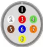 | Black | 1 | IO | Opto-isolated input (default Trigger In) |
| White | 2 O1 | Opto-isolated output | ||
| Red | 3 | IO2 | Input/Output/serial transmit (TX) | |
| Green | 4 | IO3 | Input/Output/serial receive (RX) | |
| Brown | 5 | GND | Ground for bi-directional IO, V3.3 V pins | |
| Blue | 6 | OPTO_GND | Ground for opto-isolated IO pins | |
| Orange | 7 | V_EXT | Allows the camera to be powered externally | |
| Yellow | 8 | +3.3 V | Power external circuitry up to 15 | |
| To configure the GPIO pins, consult the General Purpose Input/Out of your camera's Technical Reference Manual. | ||||
Status Indicator LED
| LED Status | Description |
| Off | Not receiving power |
| Steady green, high Intensity (~5 seconds) | 1. Camera powers up |
| Green/Red, flashing (~2 seconds) | 2. Camera programs the FPGA |
| Green flashing quickly, low Intensity | 3. Establishing IP connection. The camera a to establish an IP connection in the follow |
| One green blink (~1-2 seconds)Two green blinks (~1-2 seconds)Three green blinks (~1-2 seconds)Three red blinks (~1-2 seconds) | i) A persistent IP address, if enabled and II) a DHCP address, if enabled and availab III) a link-local address (LLA).iv) Failure to establish connection |
| Steady green, high Intensity | 4. Camera is streaming Images |
| Red/Green flashing quickly | Firmware update in progress |
| Red flashing slowly | General error - contact technical support |
Camera Care
To clean the imaging surface of your camera, follow the steps outlined in Knowledge Base Article 10243.
Extended exposure to bright sunlight, rain, dusty environments, etc. may problems with the electronics and optics of the system.
Avoid excessive shaking, dropping, or mishandling of the device.

Do not open the camera housing. Doing so voids the Hardwa. Avoid electrostatic charging. For more details, consult Knowledge Base Article 10147.
Contacting Point Grey Research
For all general questions please contact us at info@ptgrey.com.
For technical support (existing customers only) contact us at www.ptgrey.com/support/ticket/.
Main Office:
section Mailing Address:
Point Grey Research, Inc.
12051 Riverside Way
Richmond, BC, Canada V6W
Tel: +1 (604) 242-9937
Toll Free1(866) 765-0827
(North America only)
Fax: +1 (604) 242-9938
1K7Email: sales@ptgrey.com
Installing Your Interface Card and Software
- Install your Interface Card
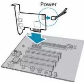
Ensure the card is installed per the manufacturer's instructions.
Connect the internal IDE or SATA power connector on the card to the computer power supply.
Alternatively, use your PC's built-in host controller, if equipped.
Installing Your Camera
- Install the Tripod Mounting Bracket (optional)
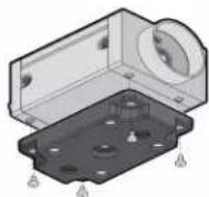
The ASA and ISO-compliant tripod mounting bracket attaches to the camera using the included plastic metal screws.

Cameras with metal cases should use metal screws; cameras with plastic cases should use plastic screws. improper screws may cause damage to the camera.
Open the Windows Device Manager. Ensure the card is properly installed under Network Adapters. An exclamation point (!) next to the card indicates 2theAttach a Lens driver has not yet been installed.
- Install the FlyCapture® Software
Unscrew the dust cap from the C-mount lens holder to install a lens
- Connect the interface Card and Cable to the Camera

For existing users who already have FlyCapture installed, we recommend ensuring you have the latest version for optimal performance of your camera. If you do not need to install FlyCapture, use the DriverControlGUI to install and enable drivers for your card.
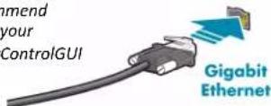
Plug the interface cable into the host controller card and the camera. The cable jack screws can be used for a secure connection.
a. Login to the Point Grey downloads page.
b. Select your Camera and Operating System from the drop-down lists and click the Search button.
c. Click on the Software search results to expand the list.
d. Click the appropriate link to begin the download and installation.
After the download is complete, the FlyCapture setup wizard begins. If Inthe GigE Configurator:
wizard does not start automatically, double-click the .exe file to open the steps in each setup dialog.
- Enable the Drivers for the card
During the FlyCapture installation, you are prompted to select your interface driver.
In the Interface Driver Selection dialog, select the I will use GigE cameras.
This selection ensures the Point Grey Image Filter driver is installed and enabled. The Image Filter Driver operates as a network service between GigE Vision cameras and the Microsoft built-in UDP stack to filter out Vision stream protocol (GVSP) packets. Use of the filter driver is recommended, as it can reduce CPU load and improve image streaming performance.
Alternatively, Point Grey GigE Vision cameras can communicate directly with the Microsoft UDP stack.
- Plug in the GPIO connector
The wiring harness must be compatible with a Hirose HR25 8-pin fer GPIO connector.
- Configure IP Settings
Inthe GigE Configurator:
it: Follow in the left pane, select your GigE Vision camera. (Note: there may be a delay of several seconds before the camera is detected by the GigE Conf on startup.)
Under "Current IP Configuration," review the IP address. By default, a dynamic IP address is assigned to the camera according to the protocol. If DHCP addressing fails, a link-local address is assigned necessary, change the IP address of the camera to be on the subnet as the NIC. If the subnets do not match, the camera "BAD" on the left pane.
SigFder "Packet Size Discover," click Discover Maximum Packet Size and note the value.
b. Close the GigE Configurator.
- Confirm Successful Installation and Configure Packet Size
a. Run the FlyCap program: Start-> FlyCapture SDK-> FlyCap
b. In the camera selection dialog, select the GigE camera that was in click Configure Selected.
c. In the Camera Control dialog, click Custom Video Modes. By default, Packet Size is set to 1400 bytes. We recommend increasing this value to noteP in the GigE Configurator, as maximizing packet size reduces overhead.
The FlyCap program can be used to test the camera's image acquisition capabilities through the Ethernet connection.
card changes to your camera's installation configuration can be made using from available in the FlyCapture SDK.

GigE Vision cameras on Linux systems use native Ubuntu drivers.
To uninstall or reconfigure the driver at any time after setup is complete, DriverControlGUI.
- Configure IP Settings
After installation is complete, the Point Grey GigE Configurator opens. allows you to configure the IP settings of the camera and network If the GigE Configurator does not open automatically, open the tool Menu>FlyCapture SDK>Utilities>GigE Configurator. If prompted to enable GigE enumeration, select Yes.
a. In the left pane, select the Local Area Connection corresponding to the network interface card (NIC) to which the camera is connected.
b. In the right pane, review maximum transmission unit (MTU). If not 9000, enable jumbo frames on the NIC by clicking Open Network Connections. (While most NICs support 9000-byte jumbo frames, this feature is often disabled by default.)
Brand : FLIR
Model : Grasshopper2
Category : Thermal camera