
DS-3T0310P - Switch Hikvision - Free user manual and instructions
Find the device manual for free DS-3T0310P Hikvision in PDF.


| Product Type | Unmanaged PoE Switch |
| Brand | Hikvision |
| Model | DS-3T0310P |
| Ports | 10 x 10/100 Mbps RJ45 PoE |
| PoE Standard | IEEE 802.3af/at |
| PoE Power Budget | 60 W |
| Switching Capacity | 1.6 Gbps |
| MAC Address Table | 1024 entries |
| Dimensions (W x D x H) | 200 x 120 x 44 mm |
| Weight | 0.6 kg |
| Power Supply | 100-240 V AC, 50/60 Hz |
| Power Consumption | ≤ 72 W (max) |
| Operating Temperature | 0 °C to 40 °C |
| Storage Temperature | -40 °C to 70 °C |
| Humidity | 5% to 90% non-condensing |
| Standards Compliance | IEEE 802.3, 802.3u, 802.3x, 802.3af/at |
| Fanless Design | Yes (silent operation) |
| Mounting | Desktop or wall-mountable |
| Safety | CE, FCC, RoHS |
| Cleaning Instructions | Wipe with a dry soft cloth; avoid liquids |
| Repairability | No user-serviceable parts; contact support for issues |
| Warranty | 2 years |
Frequently Asked Questions - DS-3T0310P Hikvision
User questions about DS-3T0310P Hikvision
0 question about this device. Answer the ones you know or ask your own.
Ask a new question about this device
Download the instructions for your Switch in PDF format for free! Find your manual DS-3T0310P - Hikvision and take your electronic device back in hand. On this page are published all the documents necessary for the use of your device. DS-3T0310P by Hikvision.
USER MANUAL DS-3T0310P Hikvision
natural_image
Abstract geometric design with red diamonds, gray squares, and a white globe symbol on a red background (no text or symbols)4/8 Series Ethernet Switch
User Manual
UD03706B
User Manual
COPYRIGHT ©2016 Hangzhou Hikvision Digital Technology Co., Ltd.
ALL RIGHTS RESERVED.
Any and all information, including, among others, wordings, pictures, graphs are the properties of Hangzhou Hikvision Digital Technology Co., Ltd. or its subsidiaries (hereinafter referred to be "Hikvision"). This user manual (hereinafter referred to be "the Manual") cannot be reproduced, changed, translated, or distributed, partially or wholly, by any means, without the prior written permission of Hikvision. Unless otherwise stipulated, Hikvision does not make any warranties, guarantees or representations, express or implied, regarding to the Manual.
About this Manual
This Manual is applicable to DS-C10S-SXXT Series Video Wall Controller.
The Manual includes instructions for using and managing the product. Pictures, charts, images and all other information hereinafter are for description and explanation only. The information contained in the Manual is subject to change, without notice, due to firmware updates or other reasons. Please find the latest version in the company website (http://overseas.hikvision.com/en/).
Please use this user manual under the guidance of professionals.
Trademarks Acknowledgement
HIKVISION
and other Hikvision's trademarks and logos are the properties of Hikvision in various Other trademarks and logos mentioned below are the properties of their respective
Legal Disclaimer
TO THE MAXIMUM EXTENT PERMITTED BY APPLICABLE LAW, THE PRODUCT DESCRIBED, WITH ITS HARDWARE, SOFTWARE AND FIRMWARE, IS PROVIDED "AS IS", WITH ALL FAULTS AND ERRORS, AND HIKVISION MAKES NO WARRANTIES, EXPRESS OR IMPLIED, INCLUDING WITHOUT LIMITATION, MERCHANTABILITY, SATISFACTORY QUALITY, FITNESS FOR A PARTICULAR PURPOSE, AND NON-INFRINGEMENT OF THIRD PARTY. IN NO EVENT WILL HIKVISION, ITS DIRECTORS, OFFICERS, EMPLOYEES, OR AGENTS BE LIABLE TO YOU FOR ANY SPECIAL, CONSEQUENTIAL, INCIDENTAL, OR INDIRECT DAMAGES, INCLUDING, AMONG OTHERS, DAMAGES FOR LOSS OF BUSINESS PROFITS, BUSINESS INTERRUPTION, OR LOSS OF DATA OR DOCUMENTATION, IN CONNECTION WITH THE USE OF THIS PRODUCT, EVEN IF HIKVISION HAS BEEN ADVISED OF THE POSSIBILITY OF SUCH DAMAGES.
REGARDING TO THE PRODUCT WITH INTERNET ACCESS, THE USE OF PRODUCT SHALL BE WHOLLY AT YOUR OWN RISKS. HIKVISION SHALL NOT TAKE ANY RESPONSIBILITES FOR ABNORMAL OPERATION, PRIVACY LEAKAGE OR OTHER DAMAGES RESULTING FROM CYBER ATTACK, HACKER ATTACK, VIRUS INSPECTION, OR OTHER INTERNET SECURITY RISKS; HOWEVER, HIKVISION WILL PROVIDE TIMELY TECHNICAL SUPPORT IF REQUIRED.
SURVEILLANCE LAWS VARY BY JURISDICTION. PLEASE CHECK ALL RELEVANT LAWS IN YOUR JURISDICTION BEFORE USING THIS PRODUCT IN ORDER TO ENSURE THAT YOUR USE CONFORMS THE APPLICABLE LAW. HIKVISION SHALL NOT BE LIABLE IN THE EVENT THAT THIS PRODUCT IS USED WITH ILLEGITIMATE PURPOSES.
IN THE EVENT OF ANY CONFLICTS BETWEEN THIS MANUAL AND THE APPLICABLE LAW, THE LATER PREVAILS.
Regulatory Information
FCC Information
Please take attention that changes or modification not expressly approved by the party responsible for compliance could void the user's authority to operate the equipment.
FCC compliance: This equipment has been tested and found to comply with the limits for a Class A digital device, pursuant to part 15 of the FCC Rules. These limits are designed to provide reasonable protection against harmful interference when the equipment is operated in a commercial environment. This equipment generates, uses, and can radiate radio frequency energy and, if not installed and used in accordance with the instruction manual, may cause harmful interference to radio communications. Operation of this equipment in a residential area is likely to cause harmful interference in which case the user will be required to correct the interference at his own expense.
FCC Conditions
This device complies with part 15 of the FCC Rules. Operation is subject to the following two conditions:
- This device may not cause harmful interference.
- This device must accept any interference received, including interference that may cause undesired operation.
EU Conformity Statement
CE
This product and - if applicable - the supplied accessories too are marked with "CE" and comply therefore with the applicable harmonized European standards listed under the EMC Directive 2014/30/EU, the LVD Directive 2014/35/EU, the RoHS Directive 2011/65/EU.

2012/19/EU (WEEE directive): Products marked with this symbol cannot be disposed of as unsorted municipal waste in the European Union. For proper recycling, return this product to your local supplier upon the purchase of equivalent new equipment, or dispose of it at designated collection points. For more information see: www.recyclethis.info

2006/66/EC (battery directive): This product contains a battery that cannot be disposed of as unsorted municipal waste in the European Union. See the product documentation for specific battery information. The battery is marked with this symbol, which may include lettering to indicate cadmium (Cd), lead (Pb), or mercury (Hg). For proper recycling, return the battery to your supplier or to a designated collection point. For more information see: www.recyclethis.info
Industry Canada ICES-003 Compliance
This device meets the CAN ICES-3 (A)/NMB-3(A) standards requirements.
Preparing for installation
The HIKVISION 4/8 Series Ethernet Switch includes the following models:
| Model | Name |
| 4 | Ethernet Switch |
| 8 |
Symbol Conventions
The symbols that may be found in this document are defined as follows.
| Symbol | Description |
 | Provides additional information to emphasize or supplement important points of the main text. |
 | Indicates a potentially hazardous situation, which if not avoided, could result in equipment damage, data loss, performance degradation, or unexpected results. |
 | Indicates a hazard with a high level of risk, which if not avoided, will result in death or serious injury. |
Table of Contents
Chapter 1 4/8 Switch Overview .... 1
1.1 Standard Configuration .... 1
Chapter 2 Installation Preparation....4
2.1 Cautions ...... 4
2.2 Safety Advice....4
2.2.1 Safety Principles....4
2.2.2 Safety Notices ....4
2.2.3 Safety Principles for Live Working....4
2.2.4 Electrostatic Discharge Damage Prevention 5
2.3 Requirements for Common Locations 5
2.3.1 Environment 5
2.3.2 Location Configuration Prevention 6
2.3.3 Cabinet Configuration....6
2.4 Installation Tools and Device 6
Chapter 3 Installing the 4/8 Switch....7
3.1 installation equipment....7
3.2 Track installation....7
3.3 connection protected ground line 8
3.4 Connecting the SFP Ports 9
3.4.1 Connecting 100M Ethernet Base-T Ports....10
3.5 Checkup after Installation 11
Chapter 4 Specifications .... 12
Chapter 1 4/8 Switch Overview
The document describes the characteristics and parameters of 4/8 and gives an overview of 4/8. (Note: the access line should not exceed 10m. The input voltage is less than 50V, the maximum output power is less than 30W, the input voltage is more than 50V, and the maximum output power is 30W.)
1.1 Standard Configuration
4/8 series switch has two parts: 4/8 IEEE802.3af/at 100M Ethernet Base-T ports, 2 gigabit Base-T ports. See the following table: (Take 8 switch as an example)
Table 1-1 Attributes of necessary ports
| Port | Features |
| Gigabit Ethernet ports | Optical port: 100/1000M SFP port, with LINK/ ACT indicators |
| 100M PoE port | Base-T port: a rate of 10/100M auto-adaptation, MDI/MDIX auto-identification, UTP(RJ45) interface |
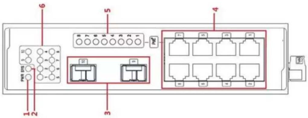
Figure 1-1 Front template of the 8 switch
| No. | Abbrev. | Name | Remarks |
| 1 | PWR | power indicator | If the switch is powered on, the indicator is on. |
| 2 | SYS | System indicator | If the indicator is always on, the system works normally. |
| 3 | / | 2 SFP ports | Realizes the forward of gigabit Ethernet optical signals. |
| 4 | / | 8 RJ45 ports | Realizes the PoE function and forwards 10/100M Ethernet electrical signals |
| 5 | PoE | PoE indicator corresponding to each port | If the indicator is always on, the PoE works normally.If the indicator is off, the PoE does not work. |
| 6 | Lnk/Act | Lnk/Act indicator corresponding to each port | Indicator lamp, indicating detectionThe indicator light is always bright, indicating LINK,The indicator light is always bright, indicating LINK, indicating lights flashing, indicating data transceiver. |
Table 1-2 Parts at the front template of the 8 switch
Besides, 4/8 switch provides with a grounding column and a power socket.
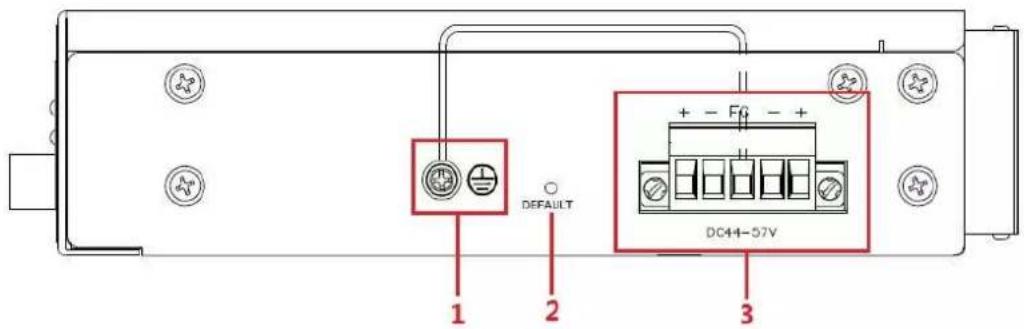
Figure 1-2 Back template of the 8 switch
Table 1-3 Parts at the rear template of the 4/8 switch
| No. | Abbrev. | Name | Remarks |
| 1 | / | The grounding column | The grounding must be fine. |
| 2 | / | DEFAULT | Press DEFAULT key for more than 5 seconds to restore to factory settings. |
| 2 | / | DC power socket | 44~57VDC |
Chapter 2 Installation Preparation
2.1 Cautions
Similar to other electronic products, the semiconductor chip easily gets damaged if you power on and off abruptly and frequently. To restart up the switch of 4/8 switch, you have to open the power on-off three or five seconds after the power is cut off.
Avoid severe collision or falling down from the height to protect the parts in the switch.
Use correct outside ports to connect the switch of 4/8 switch. Do not insert the Ethernet plug into the console port (RJ45 8-line socket). Similarly, do not insert the console cable into the console port (RJ45 8-line socket).
Note:
1) When you plug or dial out the power line, keep the power line horizontal with the power socket.
2) When the lifetime of our products ends, handle them according to national laws and regulations, or send these products to our company for collective processing.
2.2 Safety Advice
2.2.1 Safety Principles
- Keep dustless and clean during or after the installation.
- Put the cover at the safe place.
- Put tools at the right place where they are not easily falling down.
- Put on relatively tight clothes, fasten the tie or scarf well and roll up the sleeve, avoiding stumbling the chassis.
- Put on the protective glasses if the environment may cause damage to your eyes.
- Avoid incorrect operations that may cause damage to human or devices.
2.2.2 Safety Notices
The safety notices mentioned here means that improper operation may lead to body damage.
- Read the installation guide carefully before you operate the system.
- Only professionals are allowed to install or replace the switch.
- Please cut off the direct-current connection when you operate the hull or work near the power supply.
- The final configuration of products must comply with relative national laws and regulations.
2.2.3 Safety Principles for Live Working
When you work under electricity, following the following principles:
- Put off ornaments, such as ring, necklace, watch and bracelet, before you operate under live working. When metal articles connect the power to the ground, short circuit happens and components may be damaged.
- Please cut off the direct-current connection when you operate the hull or work near the power supply.
- When the power is on, do not touch the power.
- Correctly connect the device and the power socket.
- Only professionals are allowed to operate and maintain the device.
- Read the installation guide carefully before the system is powered on.
Note:
1) Check potential dangers, such as the humid floor, ungrounded extensible power line and tatty power line.
2) Install the emergent on-off at the working room for turning off the power when trouble happens.
3) Plug off the power line before installing or uninstalling the machine box or working beside the power.
4) Do not work alone if potential dangers exist.
5) Cut off the power before checkout.
6) If trouble happens, take the following measures:
A. Cut off the system's power.
B. Alarm.
C. Take proper measures to help persons who are hit by the disaster. Artificial respiration is needed if necessary.
D. Seek for medical help, or judge the loss and seek for available help.
2.2.4 Electrostatic Discharge Damage Prevention
Electrostatic discharge may damage devices and circuits. Improper treatment may cause the switch to malfunction completely or discontinuously.
Move or locate the devices according to the measures of electrostatic discharge prevention, ensuring the machine box connects the ground. Another measure is to wear the static-proof hand ring. If there is no hand ring, use the metal clip with the metal cable to clip the unpainted metal part of the machine box. In this case, the static is discharged to the ground through the metal cable of the clip. You can also discharge the static to the ground through your body.
2.3 Requirements for Common Locations
This part describes the requirements for the installation locations.
2.3.1 Environment
4/8 switch adopts the wall-mounted installation mode. The switch has no fan, so an environment with good ventilation is needed for the heat cooling of the switch.
For location planning and device locating, refer to section 2.3.2 "Location Configuration Prevention".
2.3.2 Location Configuration Prevention
The following preventive measures assist you to design the proper environment for the switch.
- Make sure that the workshop is well-ventilated, the heat of TX devices is well-discharged and sufficient air circulation is provided for device cooling.
- Put the chassis at the place where cool air can blow off the heat inside the chassis. Make sure the chassis is sealed because the opened chassis will reverse the cool air flow.
2.3.3 Cabinet Configuration
The following content assists you to make a proper cabinet configuration:
- Each device on the cabinet gives off heat when it runs. Therefore, the sealed cabinet must have the heat-discharge outlet and the cooling fan. Do not put the devices too close, avoiding bad ventilation.
- When you install the chassis at the open cabinet, prevent the frame of the cabinet from blocking the airway of the chassis.
- Ensure that nice ventilation is provided for the devices installed at the bottom of the cabinet.
- The clapboard separates exhaust gas and inflow air, and boost the cool air to flow in the chassis. The best location of the clapboard is decided by the air flow mode in the chassis, which can be obtained through different location tests.
2.4 Installation Tools and Device
The tools and devices to install the 4/8 switch are not provided by the 4/8 switch. You yourself need to prepare them. The following are the tools and devices needed for the typical installation of the 4/8 switch:
- Screwdriver
- Static armguard
- Bolt
- Ethernet cable
● Other Ethernet terminal devices - Control terminal
Chapter 3 Installing the 4/8 Switch
Caution:
Only professionals are allowed to install or replace the devices of the switch.
3.1 installation equipment
The switch adopts the way of clamping rail installation. Please select the most suitable installation location according to the specific installation environment
3.2 Track installation
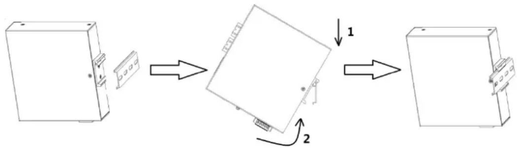
The switch supports card rail installation, and the specific installation steps are as follows:
- select the installation location of the switch to ensure that there is adequate installation space.
- insert the upper part of the DIN card rail seat into the DIN rail and rotate the device at the lower end of the switch, as shown in the arrow 2 in the next figure, and card the DIN card rail into the DIN rail to ensure that the device is safely and reliably installed on the DIN rail as shown in the following diagram.
flowchart
graph TD
    A["Initial State"] --> B["Intermediate State"]
    B --> C["Final State"]
    style A fill:#f9f,stroke:#333
    style B fill:#ccf,stroke:#333
    style C fill:#cfc,stroke:#333
Figure 3-1 track installation diagram
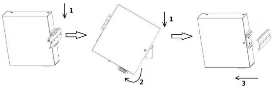
The demolition process is similar to the installation process. The specific steps are as follows:
- as shown in arrow 1 below, press down the switch slightly down.
- switch the switch in the direction of arrow 2 and move the lower end of the switch outward. If arrow 3 shows, the device can be removed from the DIN rail.
flowchart
graph TD
    A["Step 1: Initial block"] --> B["Step 2: Rotation arrow"]
    B --> C["Step 3: Final device with directional arrows"]
Figure 3-2 track installation diagram
3.3 connection protected ground line
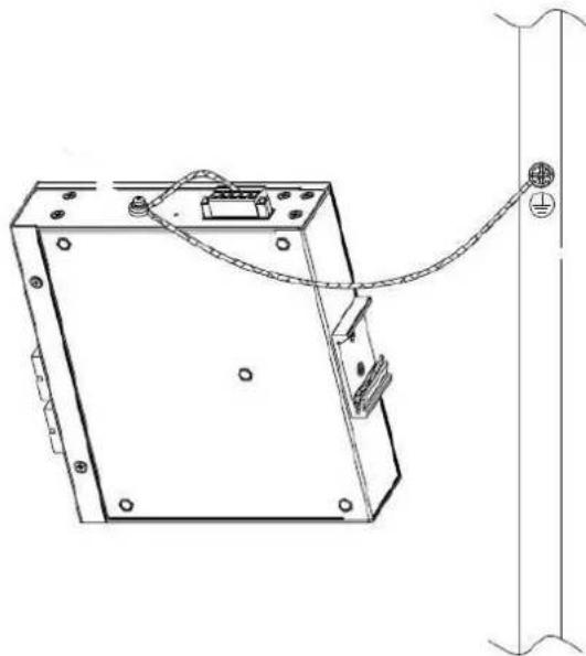
Connecting the ground wire is not only to release the overvoltage and overcurrent caused by lightning stroke as soon as possible, but also a necessary measure to ensure personal safety.
The side panel of the industrial switchboard provides a grounding bolt, which is an important guarantee for the equipment to prevent thunder and prevent interference, so the user must be grounded correctly. The GND pin on the power supply terminal has been connected to the ground screw and grounded before power up. As shown in the figure below, unscrew the combined screws on the housing.
● the line that is drawn from the GND foot on the power terminal.
- is the grounding wire, one end of which is placed on the gasket after the cold pressure terminal is pressed. According to the order shown below, the earth screws are fixed on the "shell ground" with the grounding screws, and the other end is reliably connected to the earth. When the power is broken, the grounding wire is broken. The applicable power line diameter is 10AWG; the applicable fastening torque is 5NM\~6NM; please use the stainless steel M4 nut to lock.
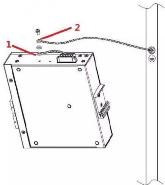
Figure 3-3 track Equipment grounding
natural_image
Technical line drawing of a mechanical or electrical component with mounting holes and wiring (no text or symbols)Figure 3-4 track Ground completion schematic
3.4 Connecting the SFP Ports
4/8 switch provides 2 gigabit SFP optical ports. Each port corresponds to one indicator respectively, which is used for indicating the port Link/ACT state. When the indicator is always on, the link is normal; when it flickers, the data receives and forwards. To use the optical port, you need connect it to the SFP optical module, and then to other Ethernet terminal devices through an optical fiber. (Take 8 switch as an example)
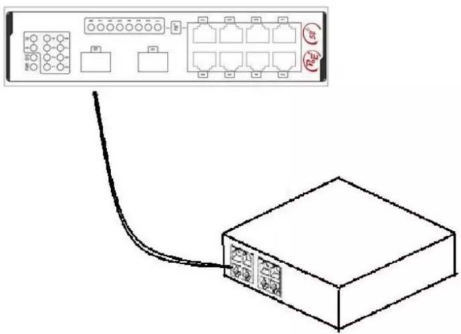
Figure 3-5 Connecting the SFP ports and other Ethernet terminals
3.4.1 Connecting 100M Ethernet Base-T Ports
The 4/8 switch has 4/8 10/100Base-TX ports. Each port has one indicator, which indicates the state of Link/ACT. If the indicator is always on, the port is linked up; if the indicator flickers, the data is transmitted on the port. The numbering order of the pins in the UTP port is the same as the console port.
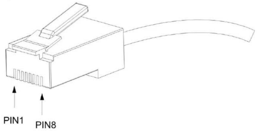
Figure 3-6 RJ-45 connector of the console port
Because 8 10/100Base-TX ports of 8 switch support the MDI/MDIX auto-identification of the cable, 4/8 switch can adopt five classes of direct-through/cross network cables when it connects other Ethernet terminals. (Take 8 switch as an example)
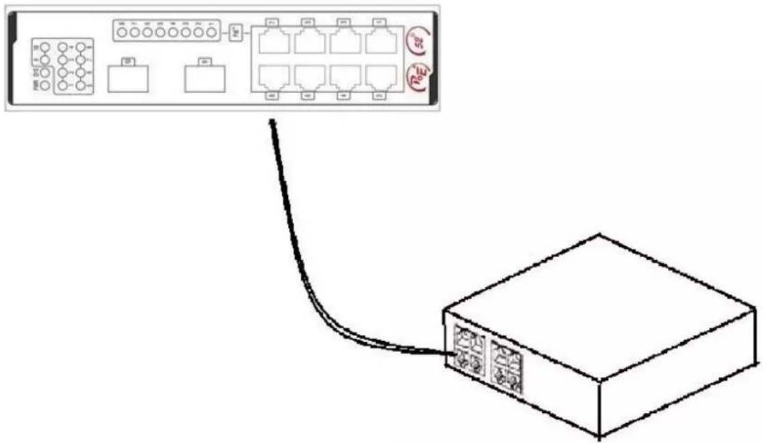
Figure 3-7 Connecting Base-T ports and other Ethernet terminal
| No. | Pin name | Symbol | Note |
| 1 | Sending the normal phase of the data | TXD1+ | Output |
| 2 | Sending the paraphase of the data | TXD1- | Output |
| 3 | Receiving the normal phase of the data | RXD1+ | Input |
| 4 | Sending the normal phase of the data | TXD2+ | Output |
| 5 | Sending the paraphase of the data | TXD2- | Output |
| 6 | Receiving the paraphase of the data | RXD1- | Input |
| 7 | Receiving the paraphase of the data | RXD2+ | Input |
| 8 | Sending the paraphase of the data | RXD1- | Input |
Table 3-1 Definition of the pins of the RJ45 port
The direct-through or cross network cable has the function of auto-identification, so the five classes of direct-through/cross network cables can be used to connect other Ethernet devices.
3.5 Checkup after Installation
Before feeding power to start the switch, perform the following checkups after the switch is installed:
- If the switch is installed on the DIN rail, check whether the installation is strong. If the switch is installed on the desk, check whether there is enough space for the switch to discharge its heat and whether the desk is stable.
- Check whether the connected power supply meets the power requirements of the switch.
- Check whether the grounding line of 4/8 switch is correctly connected.
- Check whether 4/8 switch is correctly connected to other terminal devices.
Chapter 4 Specifications
| Item | DS-3T0306P | DS-3T0310P |
| Backplane | 8.8Gbps | 8.8Gbps |
| Forwarding rate | 3.6Mpps | 4.2Mpps |
| MAC | 4K | 4K |
| Ports | 4 100M Base-T ports+2 1000Base-X ports | 8 100M Base-T ports+2 1000Base-X ports |
| Dimensions(W× D× H)(mm) | 155x130x42 | 170x156x42 |
| Consumption | <9W | <9W |
| POE/POE+ | Support | Support |
| Power supply | DC: 44 ~ 57VDC | |
| Environment | Operating temperature/humidity: -40°C-75°C, 5%-95% non-condensingStorage temperature/humidity: -40°C-85°C; 5%-95% non-condensing | |
| Protection Grade | IP40 | |
| EMI | FCC 47 CFR Part 15 Class AEN55022 Class A | |
| EMS | IEC (EN)61000-4-2, Class 4IEC (EN)61000-4-4, Class 2IEC (EN)61000-4-5, Class 2IEC (EN)61000-4-11, Class 4IEC (EN)61000-4-12, Class 4 | |
First Choice for Security Professionals
- User Manual
- ALL RIGHTS RESERVED.
- About this Manual
- Trademarks Acknowledgement
- HIKVISION
- Legal Disclaimer
- Regulatory Information
- FCC Information
- FCC Conditions
- EU Conformity Statement
- Industry Canada ICES-003 Compliance
- Preparing for installation
- Symbol Conventions
- Table of Contents
- Chapter 1 4/8 Switch Overview
- Standard Configuration
- Chapter 2 Installation Preparation
- Cautions
- Note:
- Safety Advice
- Safety Principles
- Safety Notices
- Safety Principles for Live Working
- Electrostatic Discharge Damage Prevention
- Requirements for Common Locations
- Environment
- Location Configuration Prevention
- Cabinet Configuration
- Installation Tools and Device
- Chapter 3 Installing the 4/8 Switch
- installation equipment
- Track installation
- connection protected ground line
- Connecting the SFP Ports
- Connecting 100M Ethernet Base-T Ports
- Checkup after Installation
- First Choice for Security Professionals
Brand : Hikvision
Model : DS-3T0310P
Category : Switch