
MX-14XE - Deep fryer Anets - Free user manual and instructions
Find the device manual for free MX-14XE Anets in PDF.


| Product Type | Deep Fryer |
| Brand | Anets |
| Model | MX-14XE |
| Energy Type | Gas (Natural Gas or Propane) |
| Gas Input (BTU/hr) | 111,000 |
| Gas Supply Pressure (Natural Gas) | 6" W.C. minimum |
| Gas Supply Pressure (Propane) | 11" W.C. minimum |
| Manifold Pressure (Natural Gas) | 3.5" W.C. |
| Manifold Pressure (Propane) | 10" W.C. |
| Electrical Requirements | 120 V, 60 Hz, 1-phase, 2 A |
| Kettle Capacity (Shortening) | 35-50 lb (3.5-6 gal) |
| Number of Kettles | 1 |
| Material | Stainless Steel |
| Legs | 4 adjustable legs (standard) |
| Optional Casters | Available (2 locking front, 2 fixed rear) |
| Pilot Ignition | Piezo-electric spark igniter with dual pilots |
| Temperature Control | Thermostat with knob |
| Safety Features | High-limit thermostat, gas control valve with safety shutoff, restraining device required |
| Accessories Included | 2 fryer baskets, 1 screen, 4 adjustable legs, 1 drain valve extension, 1 basket hanger |
| Ventilation Clearance | 10" minimum from flue top to hood |
| Warranty | 1 year parts and labor; 10-year frypot (parts only) for Gold Line |
Frequently Asked Questions - MX-14XE Anets
User questions about MX-14XE Anets
0 question about this device. Answer the ones you know or ask your own.
Ask a new question about this device
Download the instructions for your Deep fryer in PDF format for free! Find your manual MX-14XE - Anets and take your electronic device back in hand. On this page are published all the documents necessary for the use of your device. MX-14XE by Anets.
USER MANUAL MX-14XE Anets
Anets, Inc PO Box 501, Concord, NH 03302-0501
Tel: 603-225-6684 Fax: 603-225-5231

natural_image
Modern stainless steel kitchen appliance with dual fins and wheels (no visible text or symbols)MX-14E shown with optional casters
ANETS
FRYER
Models
MX-14E, MX-14-2E,
MX-7E,
MX-14AA, MX-14-2AA,
MX-7A
Installation,
User Operation,
&
Maintenance
Manual

DANGER
Improper installation, adjustment, alteration, service, or maintenance can cause property damage, injury or death. Read the installation, operating and maintenance instructions thoroughly before installing or servicing this equipment.

FOR YOUR SAFETY
DO NOT store or use gasoline or other flammable vapors or liquids in the vicinity of this or any other appliance.

WARNING
After installation of this equipment, immediately contact your local gas supplier to obtain information about what action to take whenever any person smells gas. Post this information in a prominent location.
Keep this Manual in a Convenient Location for Reference
CONTENTS
Shipping Container Inspection .... 3
Fryer Gas Supply Specifications ....4
Fryer Electrical Specifications ....5
Figure 1 - Fryer MX-14E Wiring Diagram .... 5
Code Requirements 6
Figure 2 - Fryer Site Installation Requirements ....6
Installation Requirements 7
Installation Instructions ....7
Leg Installation Instructions ....7
Figure 3 - Typical Leg Installation .... 8
Leg Leveling Instructions ....8
Caster Installation Instructions ....8
Figure 4 - Typical Caster Installation ...... 9
Caster Leveling Instructions 9
Fryer Restraining Device Installation Instructions 10
Gas & Electric Connection Instructions 10
Fryer Operating Instructions 11
Fryer Preparation For Use (“Boil Out” Instructions) ......12
Figure 5 - Draining the Kettle .... 12
Lighting Procedure 13
Figure 6 - Gas Control Valve & Knob Positions ..... 13
Shutdown Procedure 14
Food Product Frying Time Charts 15, 16
Daily Cleaning Procedure 17
Monthly Maintenance Instructions 18
Fryer Troubleshooting Guide 19 - 26
Fryer Warranty 27

DANGER
Read these specifications, Code Requirements, Installation Requirements, Installation Instructions, and Operating Instructions very carefully. Failure to follow the Instructions could cause the fryer to malfunction. A fryer malfunction can result in property damage, serious bodily injury, or death.
SHIPPING CONTAINER INSPECTION
- Carefully examine the shipping container for external damage. When damage is noted, notify the delivery carrier immediately. Save all packing materials for damage claim examination.
- If no external damage is noted, remove the shipping container from the fryer and examine the fryer carefully for damage. Place the fryer in a safe location, if damage is noted, so that the freight damage claims adjuster can examine the fryer.
- Save the shipping container for use during leg/caster installation. Refer to the Installation Instructions for that procedure.
Models Covered By This Manual
| MX-14E | High Efficiency Stainless Steel Fryer |
| MX-14-2E | High Efficiency Stainless Steel Split Pot Fryer |
| MX-14-7E | High Efficiency Stainless Steel Half Size Fryer |
| MX-14A A | High Efficiency Stainless Steel Fryer With Automatic Lifts |
| MX-14-2AA | High Efficiency Stainless Steel Split Pot Fryer With Automatic Lifts |
| MX-7A | High Efficiency Stainless Steel Half Size Fryer With Automatic Lifts |
Standard Accessories furnished in the shipping carton with this fryer include:
Models MX-14AA, -14-2AA, MX-14E, and MX-14-2E Models MX-7A and MX-7E
2 Fryer Baskets 1 Screen 1 Fryer Basket 1 Screen
4 Adjustable Legs 1 Basket Hanger* 4 Adjustable Legs 1 Basket Hanger*
1 Drain Valve Extension 2 Basket Lift Frames ** 1 Drain Valve Extension 1 Basket Lift Frame **
*- Basket Hanger for MX-14E, MX-14-2E, or MX-7E only.
** - Basket Lift Frame for MX-14AA, MX-14-2AA, or MX-7A only.
NOTE: Other available optional equipment may include a sediment tray; a microprocessor-based cooking computer with shortening melter, boil-out mode, and digital timers (Fri-tronic ^® ); a built-in filter system (Filtronic ^™ II or Filter Mate ^™ ); a fryer cover; a drain table; a front drain tray; or four casters.
NOTE: A Parts List for each Anets Fryer is among the items shipped with each fryer. If an additional copy of this list is needed, please contact the factory as directed on the back cover.
FRYER GAS SUPPLY SPECIFICATIONS
Please make sure that your desired fryer location has gas supply factors that are suitable for this product:
Models MX-14E, MX-14-2E, MX-14AA, &MX-14-2AA
| INPUT REQUIRED:111,000 BTU/Hr * | Natural Gas Propane Gas | |
| MANIFOLD PRESSURE | 3 12 " W.C. ** | 10" W.C. |
| SUPPLY PRESSURE*** | 6" W.C., minimum 11" | W.C., minimum |
Models MX-7E & MX-7A
| INPUT REQUIRED:55,000 BTU/Hr * | Natural Gas Propane Gas | |
| MANIFOLD PRESSURE | 3 12 " W.C. ** | 10" W.C. |
| SUPPLY PRESSURE*** | 6" W.C., minimum | 11 " W.C., mini- |
* - BTU/Hr Rating is based on sea level operation. For sites above 2000 feet, reduce this rating 4% for each 1000 feet above sea level.
** - " W.C. = Inches, Water Column.
*** - Measure Supply Pressure when all other gas-powered equipment is operating.
Gas Supply Inlet Pipe must be 34 " NPT (National Pipe Thread) standard gas line. The gas supply inlet line should be as straight as possible (fewest bends or elbows) to obtain the highest available gas pressure at the appliance. Locate this inlet line horizontally at the center of the desired fryer location, approximately 814 " above the floor.
NOTE: Using a flexible inlet line permits variation in the gas supply line location, both horizontally and vertically.
Anets fryers are only for use with the type of gas specified on the spec plate. If a fryer requires modification to use a gas other than that which is identified on the fryer spec plate, contact your Anets representative or call (1-603-225-6684.
FRYER ELECTRICAL SPECIFICATIONS
Please make sure that your desired fryer location has electrical supply factors that are suitable for this product:
120 Volts, 60 Hz, (Refer to Table 1 for amperage requirements), 1-phase, three-wire connection, including an electrical ground, via a dedicated circuit breaker. A model-specific electrical circuit diagram is mounted inside the front door of each fryer.
Table 1. Fryer Amperage Requirements
| Model | Amperage |
| MX-14E | 2 A. |
| MX-14-2E | 4 A. |
| MX-7E | 2 A. |
| MX-14AA | 7 A. |
| MX-14-2AA | 9 A. |
| MX-7A | 5 A. |
Install a dedicated, three-prong, outlet/ receptacle within 5 feet of the desired fryer location to allow the fryer's power cable to be connected. Ensure that the green (ground) wire of the fryer's power cable is attached to the fryer's structure, providing an electrical ground in accordance with applicable local codes, or in the absence of local codes, with the National Electrical Code, ANSI/NFPA 70 (latest edition) or the Canadian Electrical Code, CSA C22.1 (latest edition) and CSA C22.2 (latest edition).
Figure 1 is the basic wiring diagram of an MX-series fryer showing a typical circuit. Some fryers may have other options that do not appear in this basic wiring diagram. A model-specific wiring diagram included with each fryer shows all the actual parts and their associated wiring connections. In addition, fryers equipped with a built-in filter system (Filtronic II or Filter Mate) and/or built-in computer controls (Fri-tronic) have a supplementary manual included for each option.

WARNING
Electrical Grounding Instructions
(See inside of door for wiring diagram.) This appliance is equipped with a three-prong (grounding) plug for your protection against shock hazard, and should be plugged directly into a properly grounded, three-prong receptacle. DO NOT cut or remove the grounding prong from this plug.

flowchart
graph TD
    A["PLUG 120 VAC 60 Hz"] --> B["BURNER INDICATOR"]
    B --> C["CONTROL THERMOSTAT"]
    C --> D["POWER SWITCH"]
    D --> E["THERMOSTAT PROBE"]
    E --> F["THERMOCOUPLE"]
    F --> G["DUAL PILOT"]
    G --> H["SPARK IGNITOR"]
    H --> I["HIGH LIMIT"]
    style A fill:#f9f,stroke:#333
    style B fill:#ccf,stroke:#333
    style C fill:#cfc,stroke:#333
    style D fill:#fcc,stroke:#333
    style E fill:#cff,stroke:#333
    style F fill:#ffc,stroke:#333
    style G fill:#cfc,stroke:#333
    style H fill:#fcc,stroke:#333
    style I fill:#fff,stroke:#333
Figure 1. Fryer Model MX-14E Wiring Diagram
CODE REQUIREMENTS
IMPORTANT: Read the Code Requirements and the Installation Requirements and Instructions carefully, before starting the installation. Contact the factory 1-603-225-6684 if any problems or questions arise.
The fryer installation must conform with local codes, or in the absence of local codes, with the National Fuel Gas Code, ANSI Z223.1 (latest edition); the Natural Gas Installation Code, CAN/CGA-B149.1 (latest edition); or the Propane Gas Installation Code, CAN/CGA-B149.2 (latest edition), as applicable, including:
a. Disconnect the fryer and its individual shutoff valve from the gas supply piping system during any pressure testing of the gas supply system at test pressures in excess of 12 psig (3.45 kPa).
b. Isolate the fryer from the gas supply piping system during any pressure testing of the gas supply system at test pressures equal to or less than 12 psig (3.45 kPa).
c. For fryers utilizing floor casters, the fryer installation shall be made with a connector that complies with the Standard for Connectors for Movable Gas Appliances, ANSI Z21.69 (latest edition) or CAN/CGA 6.16 (latest edition), and a quick-disconnect device that complies with the Standard for Quick-Disconnect Devices for Use with Gas Fuel, ANSI Z21.41 or CAN/CGA 1-6.9 (latest edition).
d. Restrict the movement of a caster-equipped fryer by using a limiting device (for example, a cable attached both to the fryer and to a fixture attached to the site structure) to avoid depending on the connector and the quick-disconnect device or its associated piping to limit fryer movement.
e. Install this fryer on a non-combustible floor with its back and sides at least 6" away from any combustible wall, as shown in Figure 2.

WARNING
Install this fryer under a ventilation hood that conducts combustion products outside the building. Venting must comply with ANSI/NFPA 96 (latest edition).
f. Install this fryer in a location where adequate combustion and ventilation air is available. Keep the area directly in front of the fryer open for adequate air flow to the burners. DO NOT obstruct the flow of combustion and ventilation air.
g. Keep the fryer area free and clear from combustibles and debris.
h. Attach a restraining device to each fryer, to prevent the unit from tipping, which could cause splashing of hot liquid.
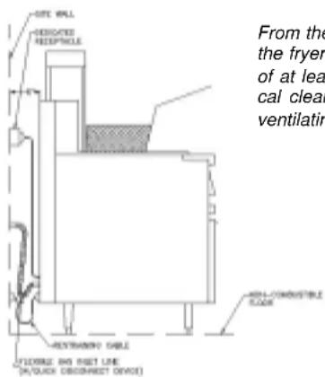
From the top of the flue on the fryer, allow a minimum of at least 10 inches vertical clearance beneath a ventilating hood.

Figure 2. Fryer Site Installation Requirements
INSTALLATION REQUIREMENTS
Install the fryer in accordance with the preceding Code Requirements, as well as the following Installation Requirements.
- DO NOT install this fryer in a mobile home, trailer, or recreational vehicle.
- Install this fryer in a location that has the fryer's electrical receptacle nearby (5 feet or less away) to avoid straining the fryer's power cord. (See Figure 2.)
- Install this fryer in a location that allows it to be moved away from other adjacent appliances for cleaning and maintenance.
NOTE: If the fryer is installed among a row of appliances (“banked”), with its only convenient movement forward, sufficient room must be available in front of the fryer to permit its separation from adjacent appliances for cleaning and maintenance.
- Tightly fasten the legs (or casters) to the bottom of the fryer using the supplied hardware, to prevent the fryer from tipping, wobbling or rocking when it is in its desired location. Refer to the following Leg Installation Instructions or Caster Installation Instructions for leg or caster attachment and leveling information.

CAUTION: Hood make-up air MUST NOT flow in a manner that restricts or impedes the natural flow of combustion or ventilation air.
- Confirm that the air from the ventilation hood flowing near the fryer after installation is NOT blowing on the rear of the unit, to prevent affecting the burner flames and possibly causing damage to plastic parts.
INSTALLATION INSTRUCTIONS
LEG INSTALLATION INSTRUCTIONS
- Flatten the shipping carton (after unpacking the fryer and its parts and accessories) for fryer surface protection during leg installation.
- Position the side of the fryer flat on the carton, exposing the fryer bottom mounting brackets for leg installation, as shown in Figure 3.
- Place the leg mounting plate flush against the mounting bracket on the fryer bottom, while aligning the mounting holes.
-
Insert one mounting bolt through a flat washer and then through the proper hole in the fryer mounting bracket and through the leg mounting plate.
-
Screw a locking nut several turns onto the mounting bolt.
- Repeat steps 4 and 5 until all four mounting bolts for a leg are in place with locking nuts.
- Tighten the four locking nuts evenly and securely to hold the leg mounting plate against the fryer bottom mounting bracket.
INSTALLATION INSTRUCTIONS (Continued)

Figure 3. Typical Leg Installation
LEG LEVELING INSTRUCTIONS
- Move the fryer to its desired location.

WARNING
The fryer MUST NOT tip, rock or wobble, to avoid splashing or spilling its HOT shortening contents during operation.
CASTER INSTALLATION INSTRUCTIONS
- Flatten the shipping carton (after unpacking the fryer and its parts and accessories) for surface protection during caster installation.
- Position the side of the fryer flat on the carton, exposing the fryer bottom mounting brackets for caster installation, as shown in Figure 4.
- Mount locking casters on the front of the fryer and fixed casters on the rear, by placing each caster mounting plate flush against the mounting bracket on the fryer bottom.
-
Insert one mounting bolt through a flatwasher
-
Turn the screw-type leg adjustment ends as necessary to level the fryer, until NO tipping, rocking, or wobbling is evident.
- Perform the Fryer Restraining Device Installation Instructions, referring to Figure 2.
(supplied) and the mounting bracket, then through the caster mounting plate.
- Screw a locking nut several turns onto the mounting bolt.
- Repeat steps 4 and 5 until all four mounting bolts for a caster are in place with locking nuts.
- Tighten the four bolts evenly and securely to hold the caster mounting plate against the fryer mounting bracket.
INSTALLATION INSTRUCTIONS (Continued)

Figure 4. Typical Caster Installation
CASTER LEVELING INSTRUCTIONS
- Move the fryer to its desired location.
- Determine whether the fryer tends to wobble or rock when in its desired location. If it does, perform steps 3 through 9. If it does not, skip to step 10, then proceed to the Installation Instructions.

WARNING
The fryer MUST NOT tip, rock or wobble, to avoid splashing or spilling its HOT shortening contents during operation.
-
Determine which caster requires adjustment and the approximate amount of change required to level the fryer.
-
Position the side of the fryer on the shipping carton, exposing the bottom of the fryer with the caster mounting plates (Figure 4).
-
Completely unscrew the bolts holding the caster mounting plate that requires the leveling adjustment. Retain the locking nuts for later reassembly.
CASTER LEVELING INSTRUCTIONS (Continued)
-
Reinsert each bolt through its flatwasher and the fryer mounting bracket; next, place a spacer of the required size on the bolt before inserting the bolt through its mounting hole on the caster mounting plate and screwing a locking nut onto the bolt.
-
Repeat step 6 for all remaining bolts.
-
Tighten all four locking nuts evenly and securely against the caster mounting plate and the fryer bottom mounting bracket.
-
Return the fryer to its desired location. Lock the front casters to prevent fryer movement and check again for wobbling or rocking. Repeat steps 3 through 9 until no wobbling or rocking occurs. When the fryer no longer wobbles or rocks, perform step 10.
-
Perform the Fryer Restraining Device Installation Instructions, referring to Figure 2.
INSTALLATION INSTRUCTIONS (Continued)
FRYER RESTRAINING DEVICE INSTALLATION INSTRUCTIONS

WARNING
Fryers MUST have a movement-limiting (restraining cable) device installed to prevent tipping that causes splashing or spilling its HOT contents.
NOTE: This movement-limiting device is to be furnished and stalled by the fryer's installing contractor before the fryer is connected to the gas line at its desired location.
- Install one restraining device connector into the structure wall directly behind the fryer's desired location, as shown in Figure 2.
- Install one restraining device connector on the rear panel of the fryer very close to the quick-disconnect device on the end of the fryer's gas line.
NOTE: Avoid interfering with the lift mechanism, on AA models. - Attach one end of the restraining cable to the wall connector. Attach the other end to the fryer connector.
- Confirm that the fryer cannot move far enough away from the wall to cause excessive movement of the flexible gas line or its associated connectors.
GAS & ELECTRIC CONNECTION INSTRUCTIONS
Installing your ANETS Fryer requires the following procedure, after its legs or casters are properly attached and it is in its desired location.
- Ensure that the gas control valve knob in the fryer has its OFF position next to the valve mark.
- Ensure that the gas supply inlet line valve is closed (handle crosswise to the line direction).
- Ensure that the circuit breaker dedicated to this fryer is OFF and that all fryer controls are set to OFF.
- Connect the 34 " gas supply line to the gas line adapter on the lower rear of the fryer.

WARNING
DO NOT use a flame to check for leaks.
- Open the gas supply line valve (handle in-line with line direction); then, confirm that all gas supply line joints and couplings are free of leaks using soap suds or a leak-check solution, after the fryer is in its desired location.
- Plug the fryer's electric power cord plug into the receptacle specified for this fryer. Switch the circuit breaker to ON.
- Refer to Fryer Operating Instructions to begin using your ANETS Fryer.
FRYER OPERATING INSTRUCTIONS

CAUTION
DO NOT operate this fryer during a power outage or interruption of gas service. Turn all fryer controls to OFF, including the gas control valve knob, then close the gas supply line valve. Also, switch off the circuit breaker controlling electric power to the fryer. When notified that the power outage has ended, perform the Lighting Procedure (later in this manual).

DANGER
NEVER operate this fryer when its flue is blocked or when the ventilation hood is not on because the combustion products can accumulate and cause serious injury or death.

DANGER
Avoid moving the fryer while it contains HOT shortening. Drain the shortening from the fryer before moving it for service, cleaning, or maintenance to avoid spilling or splashing. Burns from hot shortening can cause serious injury or death.
A. An ANETS MX-14E or MX-14AA
Fryer is designed for operation with a kettle filled with approximately 35 to 50 pounds of liquid shortening. (This is approximately 3 12 to 6 gallons.)
Each kettle of an ANETS MX-14-2AA, MX-14-2E, MX-7A, or MX-7E Fryer is designed for operation with approximately 25 pounds of liquid shortening. (This is approximately 2 12 to 3 gallons.)

CAUTION: Unless this fryer is equipped with the controls permitting the melting of shortening*, DO NOT melt solid shortening in this fryer because the melting can damage the kettle, which will void the fryer warranty.
* Fryers that are shipped with multi-product cooking computers (Fri-tronic) have an automatic ‘Melt’ selection to liquefy solid shortening.
Shortening must be melted into the liquid state before it can be used in an ANETS Fryer, unless the fryer has an automated ‘melt’ selection available on its control panel.
B. Schedule regular cleanings of the fryer to ensure long-term satisfactory operation. Refer to the Daily Cleaning Procedure, later in this manual.
C. Before servicing and maintenance, allow the fryer to cool. ALWAYS shut off electricity and gas to the fryer while working on it, to prevent electric shocks or burns.
D. Contact the factory (1)608-225-6684 ranty service authorization. [Always notify the factory the next business day about ‘after-hours’ warranty service.] Contact your local restaurant equipment service agency for other service, repairs, or mainte- nance activities, as necessary.
E. When breaded food products are being cooked, ANETS recommends using the special (optional) sediment tray to capture any breading fragments that become loosened from the food product. Periodic clearing of the sediment tray reduces premature contamination of the liquid shortening from breading fragments.
FRYER OPERATING INSTRUCTIONS
(Continued)
FRYER PREPARATION FOR USE "BOIL OUT" INSTRUCTIONS
New ANETS Fryers are cleaned and leak-tested at the factory before shipping. Before using a newly installed fryer for food preparation, clean the kettle again, as follows:
- Thoroughly wipe the interior of the kettle with clean cloths. Open the front door on the lower portion of the fryer to access the drain ball valve. Open the drain ball valve (by aligning the valve handle with the drain ball valve) and wipe the entire drain line clean.
- Close the drain ball valve (turn the valve handle cross-wise to the drain ball valve). Fill the kettle with water to about 3" from the top. Add 1 to 2 cups of low sudsing soap powder, washing soda (trisodium phosphate), or deep fat fryer kettle cleaner.
- Perform the Lighting Procedure for the fryer. (Refer to the Lighting Procedure later in this manual.)
- Set the thermostat to 190^ F. Heat, but DO NOT boil the water. Stir the water to dissolve the cleaning material.

WARNING
Hot cleaning solution can cause severe burns. Take care when handling hot cleaning solution to avoid spilling or splashing the solution.
- Clean the fryer kettle for at least 20 minutes. Use a small hand mop (an optional brush can be ordered for this purpose) to clean the upper portion of the kettle (above the 3" waterline) and the top rim of the kettle.
- Shut down the fryer using the Shutdown Procedure for the fryer. Refer to the Shutdown Procedure later in this manual. For safety, allow the water to cool (below 140°F) before draining.
FRYER PREPARATION FOR USE
(Continued)

CAUTION
For a fryer with a built-in filter system, DO NOT pump the cleaning (or rinsing) solution through the filter system, to avoid damaging the filter system pump.
- Open the front door and mount the drain extension to the drain ball valve. Position a container (bucket) capable of holding HOT cleaning solution beneath the end of the drain extension to hold the cleaning solution being drained, as shown in Figure 5.

natural_image
Technical line drawing of a mechanical assembly with a cylindrical component and vertical supports (no text or symbols)Figure 5. Draining The Kettle
- Open the drain ball valve SLOWLY, to avoid splashes while draining the cleaning solution from the kettle.
- Close the drain ball valve (valve handle cross-wise) and remove the drain extension. Close the front door.
- Safely dispose of the cleaning solution.
- Fill the kettle with water to about 3" from the top. Add 2 cups of vinegar to neutralize the cleaning solution.
- Repeat steps 3 through 10 of this procedure.
- Thoroughly wipe the interior of the kettle and the drain ball valve with clean, dry, wiping cloths to remove ALL water.
- Dry the kettle thoroughly because any remaining water can cause spattering of hot shortening when the kettle is later filled and heated.
FRYER OPERATING INSTRUCTIONS
(Continued)
Normal operation of an ANETS Fryer requires that the kettle is filled with liquid shortening above the lower indent level, marked on the rear of the kettle, before lighting the fryer's pilot and turning on the main burner.

CAUTION: Shortening MUST be in liquid form to avoid scorching or discoloration and possible damage to the kettle. Damage caused by melting solid shortening will NOT be covered by the warranty.
LIGHTING PROCEDURE
NOTE: The gas line of a new fryer installation may contain a considerable amount of air which will hinder immediate lighting. You may have to press down the control knob for as long as several minutes until the pilot flame burns steadily.
- Switch the circuit breaker controlling electric power to the fryer to ON.
- Ensure that the fryer's thermostat knob is set to OFF.
- Open the gas supply line inlet valve to the fryer by aligning the gas valve handle with the gas line piping.
- Open the front door and move the right pilot viewing/lighting port cover aside.
- Turn the gas control valve knob to align the PILOT setting with the valve mark. Figure 6 shows the possible control knob positions.
- Press, and hold down, the gas control knob to allow pilot gas to flow. Push the spark igniter pushbutton several times, until the pilot flame lights. Continue holding down the control knob for at least 30 seconds until the pilot flame burns steadily, without going out.
NOTE: A match may also be used to light the pilot flame.
-
Release the control knob and observe that the pilot flame remains lighted. Close the right pilot viewing/lighting port.
-
Light the left pilot flame by opening the left pilot viewing/lighting port and applying a match to ignite the pilot flame. Close the left pilot viewing/lighting port.

CAUTION: Ensure that both pilot viewing/lighting ports are closed, to prevent excessive heat from damaging the gas controls.
- Turn the gas control valve knob to align the ON setting with the valve mark.
- Close the front door and switch the fryer POWER switch ON.
NOTE: A fryer equipped with built-in filtering system (Filtronic or Filter Mate) requires the front door to be closed before switching the POWER switch to ON. - Turn the thermostat knob to the desired temperature.

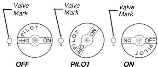
Figure 6. Gas Control Valve & Knob Positions
FRYER OPERATING INSTRUCTIONS (Continued)
SHUTDOWN PROCEDURE
NOTE: Shutdown is recommended at the end of a workday or whenever no frying is required for a period of several hours. The fryer MUST be shut down during any power outage or interruption of gas service. To prevent damage, the fryer MUST also be shutdown whenever there is no shortening in the kettle.
- Turn the thermostat knob to OFF.
- Turn the gas control valve knob to align the PILOT setting with the valve mark.
-
Open the pilot viewing/lighting port to confirm that only the pilot flame remains lighted.
-
Press, and turn, the gas control valve knob to align the OFF setting with the valve mark. Observe that the pilot flame goes out.
-
Switch the POWER switch to OFF.
NOTE: For extended periods of non-use or when servicing the fryer, close the gas supply line inlet valve to the fryer by turning the gas valve handle cross-wise with the gas line piping. Also, switch the circuit breaker for this fryer to the OFF position.
FRYER OPERATING INSTRUCTIONS (Continued)
Load the fryer basket with the food product while the basket is not in the hot liquid shortening. DO NOT overload the fryer basket. Load only a premeasured quantity of food product (1½ lb per basket, or less, if smaller portions are desired).
Model MX-14AA and MX-7A Fryers ONLY: Place the loaded fryer basket on the basket lifter frame and turn the timer control knob to the desired cooking time; press the pushbutton of the timer control to lower the loaded basket into the hot liquid shortening. When the basket of cooked food product rises from the hot liquid shortening, let it drain for approximately 15 - 30 seconds before serving.
Fryers equipped with multi-product cooking computers: Consult the instructions provided with those fryers.
NEVER increase the thermostat setting above the recommended setting to reduce the cooking time; this will produce a lower quality product and will cause more rapid shortening breakdown.
RECOMMENDED FRYING TIME FOR POTATOES
| French Fries(Typical, 1 12 lb loads) | Size | ANETSHigh PerformanceFryer | Frying Time(minutes) |
| Raw to Done | 1/4" cut | 340° F. | 5 |
| Blanched, only | 1/4" cut | 2 12 | |
| Browned, only | 1/4" cut | 2 12 | |
| Raw to Done | 3/8" cut | 6 | |
| Blanched, only | 3/8" cut | 3 | |
| Browned, only | 3/8" cut | 3 | |
| Commercially Treated | 3/8" cut | 6 | |
| Frozen, Fat Blanched | 3/8" cut | 2 | |
| Raw to Done | 1/2" cut | 7 | |
| Blanched, only | 1/2" cut | 4 | |
| Browned, only | 1/2" cut | 340° F. | 3 |
RECOMMENDED FRYING TIME FOR CHICKEN (Depending on Piece Size)
| Chicken | ANETSHigh PerformanceFryer | Frying Time(minutes) |
| Croquettes (Nuggets) | 340°F. | 3 - 4 |
| Pre-cooked, Breaded Pieces | 3 - 4 | |
| Raw to Done, Pieces* | 12 - 15 | |
| Tenders | 340°F. | 5 |
* - Usual per order = Wing, Leg, Breast, Thigh (1/2 chicken)
FRYER OPERATING INSTRUCTIONS
(Continued)
RECOMMENDED FRYING TIME FOR POPULAR FRIED FOODS
| Food Product | ANETSHigh PerformanceFryer | FryingTime(minutes) | |
| Breaded Foods | |||
| Calamari | 340°F. | 21⁄2 - 3 | |
| Cauliflower, Pre-cooked | 3 | ||
| Cheese Sticks | 3 | ||
| Clams | 1 | ||
| Egg Plant, Pre-cooked | 3 | ||
| Mushrooms | 21⁄2 - 3 | ||
| Oysters | 5 | ||
| Onion Rings | 21⁄2 - 3 | ||
| Tamale Sticks | 3 | ||
| Veal Cutlet | 3 - 4 | ||
| Calzone (Pizza Puffs) | 3 - 4 | ||
| Corn-on-the-Cob (Fresh) | 31⁄2 - 4 | ||
| Corn Dogs | 31⁄2 | ||
| Donuts, Hand-Cut, Cake | 11⁄2 | ||
| Donuts, Yeast, Raised | 1 | ||
| Fritters | 3 | ||
| French-toasted Sandwiches | 1 | ||
| Frozen Breaded Shrimp | 4 | ||
| Fresh Breaded Shrimp | 3 | ||
| Frozen Fish Fillets | 5 - 7 | ||
| Fresh Fish Fillets | 3 | ||
| Fresh Breaded Scallops | 4 | ||
| Frozen Fish Sticks | 4 | ||
| Glazed Cinnamon Apples | 3 - 5 | ||
| Tortilla Chips* | 2 - 21⁄2 | ||
| Turnovers | 340°F. | 5 - 7 | |
* - Use a second basket on top of the chips in the bottom basket, to keep them within the hot shortening; otherwise, they float before cooking completely.
FRYER OPERATING INSTRUCTIONS
(Continued)
DAILY CLEANING PROCEDURE
NOTE: Cleaning is recommended at the end of a workday, to prepare the fryer for proper operation the next time it is to be used.

DANGER
DO NOT move the fryer while it contains HOT shortening. Allow it to cool and drain the shortening from the fryer before moving it for service, cleaning or maintenance to avoid spilling or splashing. [Refer to steps 1 through 7.] Burns from HOT shortening can cause serious injury or death.
When cleaning, if relocation of your fryer is necessary, disconnect the gas supply line and unplug the electric power cable to the fryer. Also, if your fryer is caster-equipped, unlock the locking casters and disconnect the movement-limiting cable. Move the fryer as necessary to allow the following cleaning procedure to occur:
- Open the front door of the fryer. Attach the drain extension to the drain ball valve.
- Perform the Shutdown Procedure. Ensure that the gas supply line inlet valve is closed (handle cross-wise to pipe line) and the pilot flame is extinguished.
- Position a steel drum [NEVER use plastic!] with a filter cone directly beneath the drain extension end, OR if your fryer is equipped with an ANETS FiltronicII or Filter Mate unit, refer to that equipment's manual for operation details.
- Remove the fryer baskets and the sediment tray, if present, from the fryer. (If the screen is present, use the cleanout rod to lift it from the hot shortening, to avoid burns.) Clean, and rinse, these items in the sink. MAKE SURE that these items are completely dry before their next use.
DAILY CLEANING PROCEDURE
(Continued)
- Allow shortening to cool before draining. Slowly open the drain ball valve to drain the shortening. Take care to avoid spilling or splashing the shortening.
- Carefully use the Cleanout Rod to clear any sediment blocking the kettle drain. Flush out all sediment in the bottom of the kettle by pouring filtered liquid shortening into the kettle until the shortening being drained runs clear.
- Close the drain ball valve, after the kettle is completely empty of shortening and sediment. Detach the drain extension. Clean, rinse, and dry it before storing (on door bracket).

WARNING
Wait until the kettle has cooled before performing step 8, to avoid injury from burns.
-
Thoroughly wipe the kettle interior using clean cloths.
-
Periodically perform the "BOIL OUT" Instructions to ensure thorough cleaning of the kettle. (Refer to the earlier FRYER PREPARATION FOR USE section.)
-
Return the fryer to its normal operating location and reconnect both the gas supply line and the movement-limiting cable. Plug the electric power cable into its receptacle. (For caster-equipped fryers, lock the locking casters to prevent movement.)
-
Refill the kettle with filtered (or fresh) liquid shortening to the desired indent mark on the rear wall of the kettle, only if fryer operation is to continue during a subsequent shift. Otherwise, melt shortening into its liquid state and refill the kettle before fryer operation is
FRYER OPERATING INSTRUCTIONS (Continued)
DAILY CLEANING PROCEDURE
(Continued)
scheduled during the next normal working shift.
-
Return the screen (or, if used, the sediment tray) to its proper position in the kettle. Place the fryer baskets on the basket hanger (or the lifter frame) for this fryer.
-
Perform the Lighting Procedure to return the fryer to operation, when desired.
MONTHLY MAINTENANCE INSTRUCTIONS
NOTE: Regular maintenance is recommended to keep the fryer operating properly.
Once each month, before beginning fryer operation, check the flue (behind the backsplash panel) to ensure that it is clear and free of obstructions, enabling exhaust combustion gases to flow freely free flow of ventilation air. toward the ventilation hood area. DO NOT allow the flue to become excessively dirty, NEVER allow the flue to be blocked.
Monthly, observe the condition of the ventilation hood. If it shows evidence of a great deal of greasy residue, remove (clean) the residue to allow
FRYER TROUBLESHOOTING GUIDE
All service (repairs or part replacement) must be performed by a qualified Service Agency.
| PROBLEM | CAUSE | REMEDY |
| Pilot (piezo-electric) pushbutton igniter does not light the pilot flame. | 1. Electrode of igniter out of position or dirty/sooty electrode.2. Loose spark wire; loose igniter nut.3. Piezo-electric igniter does not generate a spark. | 1. Move electrode within 3/16" of pilot burner tip. Clean the electrode.2. Check spark wire connection at the igniter nut and make sure the connection is tight.3. Replace igniter mechanism (portion with pushbutton). |
| Pilot flame does not stay lighted. | 1. Dirty/sooty pilot burner.2. Low gas supply pressure [less than 6" W.C. for natural gas; (11" W.C. for propane) when all other gas-powered equipment is operating].3. Pilot flame too small to heat thermocouple.4. Pilot flame ‘wavering’ (being blown about by a draft).5. Improper thermocouple output voltage (must be at least 10 millivolts, measured at the thermocouple junction block).6. High-limit thermostat problem has shut off the gas. | 1. Clean the pilot burner. Perform the Lighting Procedure.2. Measure the gas supply pressure.Contact your local gas supplier to obtain adequate gas supply pressure.3. Adjust the pilot valve (part of the gas control valve) to increase the flame size: Unscrew and retain the slotted threaded cover; turn the pilot valve adjustment screw two turns counterclockwise; reinstall the threaded cover.4. Block or redirect the draft, to keep the flame burning steadily.5. Replace the thermocouple.6. Check for, and repair, any damaged high-limit thermostat wiring. Test the high-limit thermostat by disconnecting the thermocouple at the gas control valve. Also, disconnect the red wires to the high-limit thermostat from the gas control valve. Reconnect the thermocouple; then, perform the Lighting Procedure, to check whether the pilot flame lights. If the pilot |
| Pilot flame does not stay lighted. (Continued) | 6. High-limit thermostat problem has shut off the gas. (Continued) | 6. (Continued)flame stays lit, the high-limit thermostat has failed and must be replaced. |
| 7. Gas control valve has failed. | 7. Replace the gas control valve. | |
| Pilot flame goes out repeatedly. | 1. Low gas supply pressure [less than 6” W.C. for natural gas; (11” W.C. for propane) when all other gas-powered kitchen equipment is operating].2. Loose thermocouple or high-limit thermostat connection(s) on gas control valve.3. Pilot flame does not continuously touch the thermocouple because of excessive air flow around the pilot burner assembly.4. High-limit thermostat problem has shut off the gas. | 1. Measure the gas supply pressure.Contact your local gas supplier to obtain adequate gas supply pressure.2. Check and tighten the connections.3. Block the excessive air flow to make the pilot flame contact the thermocouple.4. Check for, and repair, any damaged high-limit thermostat wiring. Test the high-limit thermostat by disconnecting the thermocouple at the gas control valve. Also, disconnect the red wires to the high-limit thermostat from the gas control valve. Reconnect the thermocouple; then, perform the Lighting Procedure, to check whether the pilot flame lights. If the pilot flame stays lit, the high-limit thermostat has failed and must be replaced. |
| CAUTION: DO NOT return the fryer to normal operation with its high-limit thermostat bypassed/disconnected. | ||
| Main burners do not ignite. | 1. Electric power circuit breaker not switched ON.2. Electric power cord not plugged into its receptacle. | Switch the circuit breaker ON.2. Plug in the power cord. |
| Main burners do not ignite. (Continued) | 3. POWER switch of fryer not switched ON.4. Gas control valve knob set to OFF or PILOT.5. Front door open, causing the door micro-switch to actuate.NOTE: This only applies to a fryer with a built-in filter system.6. Low gas supply pressure [less than 6” W.C. for natural gas; (11” W.C. for propane) when all other gas-powered equipment is operating].7. Pilot burner problem.8. Thermostat control set below the temperature of the liquid shortening in the kettle.9. Gas control valve has failed. | 3. Press the POWER switch ON.4. Perform the normal Lighting Procedure. Turn the gas control valveknob to ON to light the main burners. If the burners do not light, the gas control valve has failed and must be replaced.5. Close the door; then switch the POWER switch OFF and back to ON. (This resets the gas control valve for proper operation.)6. Measure the gas supply pressure.Contact your local gas supplier to obtain adequate gas supply pressure.7. Refer to the preceding Pilot Burner problems and use the correct remedy.8. Increase the thermostat setting until the burners light. If this setting is greater than the desired temperature, reset the thermostat to the desired setting and allow the shortening to cool to the desired temperature.9. Replace the gas control valve. |
| Main burners do not stop burning. | 1. Thermostat has failed.2. Gas control valve has failed. | 1. Turn the thermostat control knob to OFF. If the burners do not quit burning, the thermostat has failed and must be replaced.2. Turn the gas control valve knob to OFF. If the burners do not quit burning, the gas control valve has failed and must be replaced. |
| Liquid shortening does not reach the desired for temperature for frying. | Low gas supply pressure [less than 6 " W.C. natural gas; (11 " W.C. for propane) sure, when all other gas-powered equipment is Contact operating], causing reduced heat from main burners.Low gas manifold pressure [less than 312 " W.C. for natural gas; ( 10'' W.C. for pro- the pane)].Loose knob on thermostat; or thermostat requires calibration (temperature setting differs by about 10^ from measured shortening temperature). | Measure the gas supply pres- et your local gas supplier to obtain adequate gas supply pressure.Measure the gas pressure at fryer's manifold pressure tap. Adjust the manifold pres- sure (see Figure 6), as necessary: [a] Unscrew (and re- tain) the threaded Main Burner Regulator Adjustment Cover. Use a flat-blade screwdriver to turn the regulator adjustment screw (clockwise to increase; counterclockwise to decrease) to reset the pressure adjust- ment. Reinstall, and tighten, the Regulator Adjustment Cover, when finished.Stir the shortening to mix the hot shortening with some from the lower 'cool zone' and allow it to sit for 5 minutes. Turn the thermostat knob until it 'clicks' on (causing the main burners to flame); note the setting where this occurs. Turn the thermo- stat until it 'clicks' off (causing the main burners to go out); note the setting where this occurs. Repeat this tempera- ture 'click points' step at least three times to ensure that the shortening temperature has stabilized.Measure the temperature of the shortening by inserting an accurate thermometer about 4 inches into the shortening to measure its temperature. If the temperature variation between the measured temperature and the thermostat setting is 10^ for less, the thermostat can be recalibrated. |
| Liquid shortening does not reach the desired temperature for frying. (Continued) | 3. Loose knob on thermostat; or thermostat requires calibration (temperature setting differs by about 10°F from measured shortening temperature). (Continued)4. Thermostat setting is more than 20°F different than measured shortening temperature. | 3. (Continued)Recalibrate the thermostat by: (a) removing the cap on the thermostat control knob; (b) loosening the center brass hex nut portion of the knob; (c) turn the pointer portion of the knob to the measured temperature value of the thermostat settings.Tighten the brass hex nut to lock the adjustment. Replace the cap on the knob.4. Check the thermostat setting against an accurate measure of the shortening temperature. If the temperature difference is greater than 20°F, the thermostat can possibly be recalibrated.Recalibrate the thermostat by: (a) removing the cap on the thermostat control knob; (b) loosening the center brass hex nut portion of the knob; (c) turn the pointer portion of the knob to the measured temperature.Tighten the brass hex nut to lock the adjustment. Replace the cap on the knob.If this calibration is unsuccessful, the thermostat has failed and must be replaced. |
| Basket does not lower, when the timer control pushbutton is pressed after the timer control knob is set to a time value. | 1. Electric power circuit breaker not switched ON.2. Electric power cord not plugged into its receptacle.3. POWER Switch not switched ON.4. Loosened wiring connections.5. Timer has failed. | 1. Switch the circuit breaker to ON.2. Plug in the power cord.3. Switch the POWER switch ON.4. Check wiring and tighten all connections, especially to the basket lifting devices (timer, microswitch, and motor).5. Set a time value using the timer control knob; press the push- |
| Basket does not lower, when the timer control pushbutton is pressed after the timer control knob is set to a time value. (Continued) | 5. Timer has failed. (Continued)6. Microswitch (controlling the lift motor) has failed. | 5. (Continued)button to start the timer operation. If the basket does not lower into the kettle, the timer has failed and must be replaced.To confirm that the timer is defective, connect a wire as a short circuit between the wire terminals marked “C” (white wire) and “NO” (left motor: blue wire; right motor: brown wire) on the respective timer.If the lift motor now operates to lower the basket, the timer has failed and must be replaced.If the lift motor still does not operate, the microswitch or the motor may have failed. Refer to Cause 6 of this problem.6. Set a time value using the timer control knob; press the push-button to start the timer operation. Check for 120-volt power by measuring between the “C” terminal (white wire) and the “NO” terminal (left motor: black wire; right motor: brown wire) of the microswitch. If no 120-volt power is present between these respective terminals, the microswitch is defective and must be replaced. If 120-volt power is present, but the motor still does not operate, the motor has failed and must be replaced. |
| Basket does not raise, after the timer control knob reaches a timer value of 0 (zero). | 1. Lifting mechanism or motor has failed. | 1. If the motor operates, but the basket doesn’t raise, observe whether the motor crank assembly moves. If the motor crank assembly does not move, yet the motor shaft is turning, the shear pin in the motor shaft is broken and must be replaced. |
| Basket does not raise, after the timer control knob reaches a timer value of 0 (zero). | 1. Lifting mechanism or motor has failed. (Continued) | 1. (Continued)If the motor operates, but the motor shaft is not turning, the gear inside the lift motor has failed and the lift motor must be replaced.If the motor does not operate, check for 120-volt power between the motor's terminals. If 120-volt power is present between the motor terminals, yet the motor does not operate, the motor has failed and must be replaced.If no 120-volt power is present between the motor terminals, the microswitch or timer has failed and must be replaced.Refer to the following “Causes” 2 and 3. |
| 2. Microswitch has failed. | 2. Check for 120-volt power by measuring between the “C” terminal (white wire) and the “NO” terminal (left motor: black wire; right motor: brown wire) of the microswitch. If 120-volt power is present between these respective terminals but the motor does not operate, the microswitch has failed and must be replaced. | |
| 3. Timer has failed. | 3. If no 120-volt power is present between the microswitch terminals “C” and “NO”, the timer has failed and must be replaced. | |
| Basket lowers and raises, repeatedly. | 1. Lifting mechanism microswitch is improperly positioned. | 1. Position the microswitch properly. |
| Basket raises, after the timer control knob reaches a timer value of 0 (zero), but then sinks back into the | 1. Lift motor has failed. | 1. Replace the lift motor. |
| HEATING indicator is off, while burners are aflame. | 1. HEATING indicator wiring problem.2. Indicator has failed. | 1. Repair indicator wiring if a problem is detected. Otherwise, the indicator is defective and should be replaced.2. Replace the HEATING indicator. |
| Indicator portion of POWER switch is unlighted, while fryer is operating. | 1. POWER indicator wiring problem.2. POWER indicator has failed. | 1. Repair POWER switch/indicator wiring, if a problem is detected.2. Replace the POWER switch/indicator as a unit. |
| Fryer does not begin to operate when ON portion of POWER switch is pressed. | 1. Switch portion of POWER switch has failed. | 1. Check switch wiring for problem; repair as necessary. If no wiring problem is detected, replace the faulty POWER switch/indicator as a unit. |
NOTE: A Parts List for each Anets Fryers is among the items shipped with each fryer. If an additional copy of this list is needed, please contact the factory as directed on the back cover.
ORIGINAL EQUIPMENT LIMITED WARRANTY
General Warranty
Anets, Inc. warrants to the original user of its commercial cooking appliances and related equipment that said appliances and related equipment will be free from defects in material and workmanship under normal use for a period of one (1) year from the date of installation, with appropriate documentation, to a maximum of fifteen (15) months from the date of manufacture, subject to the following additions, exceptions, exclusions and limitations.
What is covered
This warranty is limited to the repair or replacement at the Company's option, without charge, of any part found to be defective within the warranty period and reasonable expenses incurred for freight and material for the installation of such part; in addition, the Company's obligation shall be limited to reimbursement for normal labor on such parts.
Anets, Inc. agrees to pay the Authorized Service and Parts Distributor, for any labor and material required to repair or replace, at the Company's option, any part which may fail due to defects in material or workmanship during the above general warranty period.
Silver Line Fryers
In addition to the above general warranty, for its economy fryers and cookers, the Company warrants to the original user any mild. Stainless steel fry tank or cooking vessel to be free from defects for a period of one (1) year, from the date of manufacture. Labor and freight shall be the responsibility of the end user.
Gold Line Fryers
In addition to the above general warranty, for its standard fryers and cookers, the Company warrants to the original user any stainless steel fry tank or cooking vessel to be free from defects for a period of (1) year parts and labor and 10 year Frypot or cooking vessel Part only from the date of manufacture Labor and freight shall be the responsibility of the end user.
Pasta Cooker
In addition to the above general warranty, for its standard fryers and cookers, the Company warrants to the original user any stainless steel fry tank or cooking vessel to be free from defects for a period of one (1) year parts and labor and 5 years Frypot or cooking vessel part only after year one from the date of manufacture. Labor and freight shall be the responsibility of the end user.
Limitations to Fry Tank and Cooking Vessel Warranty
After the expiration of the general warranty period, any additional warranty on fry tanks or cooking vessels shall only obligate the Company to repair or replace, at its option, any fry tank or cooking vessel which it determines to be defective. Claims under this item shall be supported by a statement detailing the defect, and the Company may require the return of the fry tank or cooking vessel claimed to be defective. Labor and freight shall be the responsibility of the end user.
How to Keep Your Warranty in Force
• Make sure any shipping damages are reported immediately . Damages of this nature are the responsibility of the carrier and must be reported by the receiver.
- Install the unit properly . This is the responsibility of the installer and the procedures are outlined in the manual.
• Do not install it in a home or residence.
- Maintain it properly. This is the responsibility of the user of the appliance and the procedures are outlined in the manual.
- Adjustments, such as calibration, leveling, tightening of fasteners or plumbing or electrical connections normally associated with initial installation. These procedures are outlined in the manual and are NOT covered by warranty.
• If it is damaged due to flood, fire or other acts of God, this is not covered under this warranty.
- Use it for what it is intended. If it is used for a purpose other than for which it was intended or designed, resulting damages are not covered under the warranty.
• Make sure that it has the correct voltage, gas supply and/or good quality water. If a failure is due to poor water quality, harsh chemical action, erratic voltage or gas supplies, these damages are not covered under the warranty.
- Do not materially alter or modify from the condition in which it left the factory.
Do not obliterate, remove or alter the serial number rating plate.
- Use only Genuine OEM parts from Anets, Inc. or its Authorized Parts and Service Distributors. Repairs are not covered by the warranty.
• If any other failure occurs which is not attributable to a defect in materials or workmanship, it is not covered.
This warranty specifically excludes parts which wear or would be replaced under normal usage, including, but not limited to, electric lamps, fuses, interior or exterior finishes, o-rings and gaskets.
Limits to the Warranty
Outside the United States of America and Canada, this warranty is limited to the replacement of parts and Anets, Inc. will not bear any other expense be it labor, mileage, freight or travel.
If any oral statements have been made regarding the appliance, these statements do not constitute warranties and are not part of the contract of sale. This limited warranty constitutes the complete, final and exclusive statement with regard to warranties.
THIS LIMITED WARRANTY IS EXCLUSIVE AND IS IN LIEU OF ALL OTHER WARRANTIES WHETHER WRITTEN, ORAL OR IMPLIED, INCLUDING, BUT NOT LIMITED TO ANY WARRANTY OF MERCHANTABILITY OR FITNESS FOR A PARTICULAR PURPOSE OR WARRANTY AGAINST LATENT DEFECTS.
Limitations of Liability
In the event of a warranty or other claim, the sole obligation of Anets, Inc. will be the repair or replacement, at the Company's option, of the appliance or the component part. This repair or replacement will be at the expense of Anets, Inc. except as limited by this warranty statement. Any repair or replacement under this warranty does not constitute an extension in time to the original warranty. Parts covered under this warranty will be repaired or replaced, at the Company's option, with new or functionally operative parts. The liability of Anets, Inc. on any claim of any kind, including claims based on warranty, express or implied contract, negligence, strict liability or any other legal theories will be exclusively the repair or replacement of the appliance. This liability will not include, and the purchaser specifically renounces any right to recover special, incidental, consequential or other damages of any kind, including, but not limited to, injuries to persons, damage to property, loss of profits or anticipated loss of the use of this appliance.
If any provision of this warranty is unenforceable under the law of any jurisdiction, that provision only will be inapplicable there, and the remainder of the warranty will remain unaffected. The maximum exclusion or limitation allowed by law will be substituted for the unenforceable provision.
How to Obtain Warranty Service
First direct your claim to the Anets, Inc. Authorized Service and Parts Distributor closest to you giving complete model, serial and code numbers, voltage, gas type, and description of the problem. Proof of the date of installation and/or the sales slip may also be required. If this procedure fails to be satisfactory, write the National Service Manager, Anets, Inc., P.O. Box 501, Concord, NH. 03302-0501. USA
This warranty gives you certain specific legal rights; you may have other rights which vary from state to state.
Anets, Inc., P.O. Box 501, Jct. I-89 & I-93 Concord, NH 03302-0501
509 Route 3A, Bow, NH 03304 USA
Tel: (603)225-6684 Fax: (603)228-5231 www.ANETS.com
L14-022 R1 Printed in U.S.A.

| In the event of problems with or questions about your order, please contact the Anets your equipment, please contact the Anets factory at: Authorized Service and Parts representative(603)-225-6684 World Wide (ASAP) covering your area, or contact AnetsWebsite Address:www.anets.com | In the event of problems with or questions about your order, please contact the Anets your equipment, please contact the Anets factory at: Authorized Service and Parts representative(603)-225-6684 World Wide (ASAP) covering your area, or contact Anetsat the number listed to the left. |
| MAILING ADDRESS – P.O. BOX 501, CONCORD, NH 03302-0501SHIPPING ADDRESS – 10 FERRY STREET, CONCORD, NH 03301 | |

- ANETS
- FRYER
- DANGER
- FOR YOUR SAFETY
- WARNING
- Keep this Manual in a Convenient Location for Reference
- CONTENTS
- SHIPPING CONTAINER INSPECTION
- FRYER GAS SUPPLY SPECIFICATIONS
- FRYER ELECTRICAL SPECIFICATIONS
- CODE REQUIREMENTS
- INSTALLATION REQUIREMENTS
- INSTALLATION INSTRUCTIONS
- LEG INSTALLATION INSTRUCTIONS
- INSTALLATION INSTRUCTIONS (Continued)
- LEG LEVELING INSTRUCTIONS
- CASTER INSTALLATION INSTRUCTIONS
- CASTER LEVELING INSTRUCTIONS
- CASTER LEVELING INSTRUCTIONS (Continued)
- FRYER RESTRAINING DEVICE INSTALLATION INSTRUCTIONS
- GAS & ELECTRIC CONNECTION INSTRUCTIONS
- FRYER OPERATING INSTRUCTIONS
- CAUTION
- FRYER PREPARATION FOR USE "BOIL OUT" INSTRUCTIONS
- FRYER PREPARATION FOR USE
- LIGHTING PROCEDURE
- FRYER OPERATING INSTRUCTIONS (Continued)
- SHUTDOWN PROCEDURE
- DAILY CLEANING PROCEDURE
- (Continued)
- MONTHLY MAINTENANCE INSTRUCTIONS
- FRYER TROUBLESHOOTING GUIDE
- ORIGINAL EQUIPMENT LIMITED WARRANTY
- General Warranty
- What is covered
- Silver Line Fryers
- Gold Line Fryers
- Pasta Cooker
- Limitations to Fry Tank and Cooking Vessel Warranty
- How to Keep Your Warranty in Force
- Limits to the Warranty
- Limitations of Liability
- How to Obtain Warranty Service
Brand : Anets
Model : MX-14XE
Category : Deep fryer