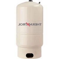
Therm-X-Trol ST-200V - Water heater Amtrol - Free user manual and instructions
Find the device manual for free Therm-X-Trol ST-200V Amtrol in PDF.


| Product Type | Water Heater Expansion Tank |
| Brand | Amtrol |
| Model | Therm-X-Trol ST-200V |
| Capacity | 2.0 Gallons |
| Maximum Working Pressure | 150 psi |
| Maximum Temperature | 200°F (93°C) |
| Pre-Charge Pressure | 40 psi |
| Connection Size | 3/4" MPT (Male Pipe Thread) |
| Material | Steel shell with butyl rubber diaphragm |
| Height | Approximately 12 inches |
| Diameter | Approximately 10 inches |
| Weight | Approximately 8 lbs |
| Orientation | Vertical or horizontal (mountable) |
| Installation | On cold water supply line to water heater |
| Function | Absorbs thermal expansion to reduce pressure buildup |
| Maintenance | Check pre-charge pressure annually; replace if leaking |
| Safety Features | Diaphragm prevents water contact with steel; ASME certified |
| Repairability | Non-repairable; replace unit if faulty |
| Warranty | Limited 3-year warranty (typical) |
Frequently Asked Questions - Therm-X-Trol ST-200V Amtrol
User questions about Therm-X-Trol ST-200V Amtrol
0 question about this device. Answer the ones you know or ask your own.
Ask a new question about this device
Download the instructions for your Water heater in PDF format for free! Find your manual Therm-X-Trol ST-200V - Amtrol and take your electronic device back in hand. On this page are published all the documents necessary for the use of your device. Therm-X-Trol ST-200V by Amtrol.
USER MANUAL Therm-X-Trol ST-200V Amtrol
Models ST-5 through ST-210V
Models T-5 and T-12

natural_image
Exterior view of a modern water tank with 'AMTROL' branding, no visible text or symbols on the main body.NOTE: Inspect for shipping damage and notify freight carrier or store where purchased immediately if damage is present. To avoid risk of personal injury and property damage, if the product appears to be malfunctioning or shows signs of corrosion, call a qualified professional immediately. Current copies of the Product manual can be viewed at www.amtrol.com. Use proper safety equipment when installing.

THIS IS THE SAFETY ALERT SYMBOL. IT IS USED TO ALERT YOU TO POTENTIAL PERSONAL INJURY AND OTHER HAZARDS. OBEY ALL SAFETY MESSAGES THAT FOLLOW THIS SYMBOL TO REDUCE THE RISK OF PERSONAL INJURY AS WELL AS PROPERTY DAMAGE.
WARNING
USE ONLY WITH RESIDENTIAL POTABLE WATER SYSTEMS. Do not operate in a setting
with freezing temperatures or where the temperature can exceed 200^ F and do not exceed the maximum working pressure specified for this Product. Do not use on a system with ASME-rated vessels.
WARNING
READ CAREFULLY THE PRODUCT INSTALLATION. OPERATING AND
MAINTENANCE MANUAL. FAILURE TO FOLLOW THE INSTRUCTIONS AND WARNINGS IN THE MANUAL MAY RESULT IN SERIOUS OR FATAL INJURY AND/OR PROPERTY DAMAGE, AND WILL VOID THE PRODUCT WARRANTY. THIS PRODUCT MUST BE INSTALLED BY A LICENSED PROFESSIONAL. FOLLOW ALL APPLICABLE LOCAL AND STATE CODES AND REGULATIONS, IN THE ABSENCE OF SUCH CODES, FOLLOW THE CURRENT EDITIONS OF THE NATIONAL PLUMBING CODE AND NATIONAL ELECTRIC CODE, AS APPLICABLE.
WARNING
This Product, like most Products under pressure, may over time corrode, weaken and burst or
explode, causing serious or fatal injury, leaking or flooding and/or property damage. To minimize risk, a licensed professional must install and periodically inspect and service the Product. Do not install this product where leaking or flooding could cause property damage to the area adjacent to the appliance or to lower floors of the structure.
WARNING
RUPTURE OR EXPLOSION HAZARD. Do not expose Product to freezing temperatures or
temperatures in excess of 200^ F. Do not adjust the pre-charge or re-pressure this Product except during installation or regular inspection. Replace the Product and do not adjust the precharge if corroded,
damaged or with diminished integrity. Adjustments to pre-charge must be done at ambient temperature only. Failure to properly size the Product or follow these instructions may result in excessive strain on the system and may lead to Product failure, serious or fatal personal injury, leakage and/or property damage.
WARNING
A relief valve must be installed to prevent pressure in excess of local code requirement or maximum
working pressure designated in the Product Manual, whichever is less. At least once every 3 years or if discharge is present, a licensed professional should inspect the temperature and pressure relief valve and replace if corrosion is evident or the valve does not function. FAILURE TO INSPECT THIS VALVE AS DIRECTED COULD RESULT IN UNSAFE TEMPERATURE OR PRESSURE BUILD-UP WHICH CAN RESULT IN PRODUCT FAILURE, SERIOUS INJURY OR DEATH AND/OR SEVERE PROPERTY DAMAGE AND VOID THE PRODUCT WARRANTY.
WARNING
Chlorine & Aggressive Water: The water quality can significantly influence the life of this Product.
You should test for corrosive elements, acidity, total solids and other relevant contaminants, including chlorine and treat your water appropriately to insure satisfactory performance and prevent premature failure.
WARNING
This product can expose you to chemicals including lead, which is known to the State of California to
cause cancer and birth defects or other reproductive harm. For more information go to www.P65Warnings.ca.gov.
PLEASE READ THE FOLLOWING INSTRUCTIONS CAREFULLY
IMPORTANT GENERAL SAFETY INFORMATION -
ADDITIONAL SPECIFIC SAFETY ALERTS APPEAR IN THE FOLLOWING INSTRUCTIONS.
Pre-Installation
1 Ensure expansion tank is sized properly for application (Figure 1).
2. Remove plastic cap from air valve.
3. With tank empty of water, adjust air precharge to match cold water supply pressure.
4. Replace and tighten plastic cap on air valve.
5. ST-5 and ST-12 only: Insert Turbulator ^™ into connector.

FAILURE TO PROPERLY SEAL VALVE CAP
WILL RESULT IN LOSS OF PRECHARGE CAUSING PRODUCT TO FAIL.
Installation
- Install the expansion tank on the cold water supply line to the water heater at a point between the water heater and backflow preventer or other one-way device (Figure 2).
Ensure that tank is
supported properly to hold the entire weight of the tank when full of water.

gh ST-210V are floor
standing and may not be hung from the piping.
- Once the expansion tank is installed, check the cold water supply line for any leakage. Make repairs if necessary.
- Before the initial firing of the water heater, open a hot water fixture and draw for one minute to purge air. Next, close and open the fixture in 30 second intervals, repeating three thimes to flush the tank and piping. Finally, turn the water heater temperature control to desired ending temperature (see water heater instructions). Do not set temperature higher than the expansion tank maximum.
- To relieve initial thermal expansion, momentarily open a hot water faucet. Continue until water heater aquastat temperature is satisfied. Once heater is at its operating range, no further bleeding of expanded water is required.
Figure 1
Expansion Tank Volume (Gal.)
Maximum Temperature Setting 140°F
| Water Heater Size (Gals.) | Static Supply Pressure (psig) | ||
| 40 60 | 80 | ||
| Tankless & POU up to 2 gal. | ST-1 | ST-1 | ST-1 |
| 40 | ST-5 | ST-5 | ST-5 |
| 50 | ST-5 | ST-5 | ST-5 |
| 60 ST-12 | ST-12 | ST-12 | |
| 80 ST-12 | ST-12 | ST-12 | |
| 120 | ST-12 | ST-12 | ST-25V |
Expansion Tank Volume (Gal.)
Maximum Temperature Setting 160°F
| Water Heater Size (Gals.) | Static Supply Pressure (psig) | ||
| 40 60 | 80 | ||
| 40 | ST-5 | ST-5 | ST-12 |
| 50 | ST-5 | ST-12 | ST-12 |
| 60 ST-12 | ST-12 ST-12 | ||
| 80 ST-12 | ST-12 ST-25V | ||
| 120 | ST-12 ST-25V | ST-25V | |
- The water heater and expansion tank will now be operational. The expansion tank will control pressure increases caused by thermal expansion to a level below the water heater relief valve setting.
Maintenance
A licensed professional should check the complete system, including the expansion tank, yearly and more frequently as the system ages. Checking the precharge allows a small quantity of air to escape and can result in an insufficient air charge. Always check the precharge while the tank is isolated and empty of water, and be sure to maintain the proper precharge whenever the tank is inspected. Monitor the tip of the indicator cap for discoloration (Figure 3) in addition to regular product inspection. Contact the installer or a plumbing professional if indicator cap is discolored; tank replacement is required. Do not rely on indicator cap as sole means of determining of tank condition.
Figure 3.
InSight® Service Indicator Cap (ST-5 and ST-12 Inline models only)

Warranty
ST-5 and ST-12 Models: Seven (7) Year Limited Warranty
ST-25V through ST-210V Models: One (1) Year Limited Warranty
T-5 and T-12 Models: One (1) Year Limited Warranty
Visit www.amtrol.com for complete warranty details.
Expansion Tank Volume (Gal.)
Maximum Temperature Setting 180°F
| Water Heater Size (Gals.) | Static Supply Pressure (psig) | ||
| 40 60 | 80 | ||
| 40 ST-12 | ST-12 ST | -12 | |
| 50 ST-12 | ST-12 ST | -12 | |
| 60 ST-12 | ST-12 ST | -25V | |
| 80 ST-12 | ST-25V | ST-25V | |
| 120 ST-25 | ST-25V | ST-25V | |
Residential sizing based on: 40°F incoming water temperature; 150 psi T&P safety relief valve; Pre-charge equal to static supply pressure.
Models: ST-5, ST-12, T-5, T-12 for residential use only.
For larger commercial applications: Visit www.amtrol.com, download the AMTROL App or contact Technical Support at 401.535.1216.
Figure 2.
In-Line Models
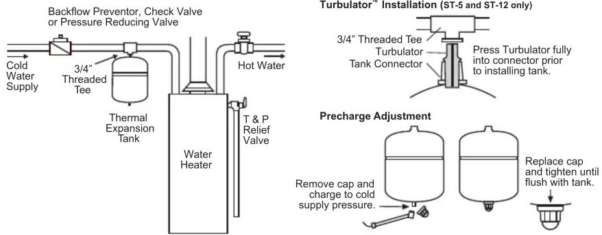
Stand Models
Backflow Preventor Check Valve or Pressure Reducing Valve

flowchart
graph LR
    A["Cold Water Supply"] --> B["Reactor"]
    B --> C["Thermal Expansion Tank"]
    C --> D["Water Heater"]
    D --> E["T & P Relief Valve"]
    E --> F["Hot Water"]

WORTHINGTON
INDUSTRIES
1400 Division Road, West Warwick, RI USA 02893
T: 800.426.8765 www.amtrol.com
© 2020 Worthington Industries Inc.
One or more features of this product are covered by U.S. patents, visit www.amtrol.com/patents for more information.



Part #: 9015-942 (06/20)
Brand : Amtrol
Model : Therm-X-Trol ST-200V
Category : Water heater