Illuminator - Uncategorized Soma - Free user manual and instructions
Find the device manual for free Illuminator Soma in PDF.


| Type of Product | LED controller / light-to-CV interface |
| Number of Channels | 8 independent channels |
| Supply Voltage | DC 12 V |
| Supply Voltage Socket | 5.5 x 2.1 mm center plus |
| Output Voltage | DC 12 V |
| Output LED Socket | 5.5 x 2.1 mm center plus |
| Maximum Total Power | 48 watts |
| Maximum Total Current | 4 A |
| Recommended Max Current per Channel | 0.5 A |
| Absolute Max Current per Channel | 1.5 A |
| Input Voltage Range | 3–20 Volts |
| Input Impedance | >5.7 kΩ (with correct sensitivity adjustment – 100 kΩ) |
| Input Sockets | 8 Eurorack mini-jacks and 9 Pulsar-23/Ornament-8 pins |
| Dimensions (WxHxD) | 275 x 70 x 40 mm |
| Weight | 300 g |
| Included Accessories | 1 Illuminator unit, 10 pcs 5.5x2.1 mm DC jacks |
| Optional Accessory | 12V 5A 60W power supply (separate purchase) |
| Compatible LED Strips | 12V LED strips; max total length 16 m (52 ft) |
| Recommended Wire | Speaker wire, copper core 0.35–1 mm² |
| Adjustment | Trimmer pots per channel for input sensitivity (default 5V) |
| Protection Features | Overload protection, short-circuit protection (with proper adjustment), reverse polarity protection on outputs |
| Advanced Use | Can drive electromagnets, motors; DC supply can vary 3-20V; peak current per channel up to 5A |
Frequently Asked Questions - Illuminator Soma
User questions about Illuminator Soma
0 question about this device. Answer the ones you know or ask your own.
Ask a new question about this device
Download the instructions for your Uncategorized in PDF format for free! Find your manual Illuminator - Soma and take your electronic device back in hand. On this page are published all the documents necessary for the use of your device. Illuminator by Soma.
USER MANUAL Illuminator Soma
natural_image
Abstract geometric logo with stylized letters (S, M, S) and shapes (circle, triangle) on black background, no text or symbols present.ILLUMINATOR
OPERATION MANUAL
ILLUMINATOR comes without LED strips, wires or PSU. The reason is simple—we don't know what colors and length of strips you need as well as what length of cables. Each installation is very personal and we can't supply something that could be called "a universal solution". You need to connect the strips yourself which requires basic soldering skills as well as simple soldering equipment. Therefore, using ILLUMINATOR requires some basic technical skills and understanding.
First of all you need to buy LED strips of desired length and color. You need 12V LED strips 1.
Typically, one meter (3 feet) of a LED strip consumes 0.2–0.35 ampere. We recommend limiting the total length of all LED strips connected to ILLU-MINATOR to a maximum of 16 meters (52 feet). Different strips connected to different channels can have different lengths.
Secondly, you need to buy wire connecting LED strips to ILLUMINATOR. We recommend standard speaker wire used for audio speakers ②. It's important that the copper core is at least 0.35 square millimeters. 0.5–1 square millimeters is the optimal thickness.
Cut your LED strips and wires into their desired lengths and connect them together and to the DC sockets supplied with ILLUMINATOR.
- LED strips have special places where you can cut the strip, usually they are copper pads like in the photo below. It's important to cut the strip on the middle line of these copper pads ③.
- You can solder the wire either directly to the copper pads or using a short wire that is often soldered to one or both ends of the LED strip by the factory. Before soldering to the copper pads you need remove the silicon layer (if present) covering the pads using a sharp knife.
- Be aware of polarity! The plus and minus on the LED strips are usually marked by + - signs. The plus wire on the speaker cable is usually marked by a special color or line on one of the wires. It doesn't really matter which of the two wires on the cable you use for plus and minus. What matters is that the plus of the LED strip is connected to the central pin on the DC jack. But don't worry. If you mix up the polarity of the strip nothing will be damaged, the strip just won't light up. In this case just try to reverse the polarity.
- The connection between the strip and the wire should be covered in several layers of isolation/electrical tape or heat shrink tubing. This serves to both isolate the connection and to give it additional mechanical strength. In case of excessive stress, this is the place where the wire will likely be ripped from the strip.
The strips are ready for use when all of them are soldered to the wires, the wires are soldered to the DC jacks and all connections are insulated.
Now you need to choose a proper power supply. You can buy a high quality PSU from us (at an additional price) or use a PSU that you already have. The PSU must be 12V and the output DC jack needs to be center plus. To calculate the current your LED strips will need, use the simple formula:
PSU max current in A is equal or more than total length of all LED strips in meters x 0.3.
If your LED installation is not big, a 1–2A PSU can be enough.
If you use a modern switching mode PSU you don't need to worry about overload. All of them have overload protection and will be shut down automatically if the load is too big. So no

natural_image
Product collage showing a 12-pin LED strip, coiled copper wire, and scissors cutting through a strip (no text or symbols visible)damage will occur. You can use a power supply that is much more powerful than your LED installation. In this case, it will just take as much power as it needs and no damage or overload will happen. It's better to use a PSU that is more powerful than what your installation needs than vice versa.
Now everything is ready to launch the ILLUMINATOR! Connect your PSU to the DC IN jack, the strips to the output jacks and CV ins to the CV outs of your analog gear using mini-jack cables or alligator clips. If you use alligator clips don't forget to connect the ground of ILLUMINATOR (the GND pin) to the ground of your CV source!
Now it's time to adjust the sensitivity of each ILLUMINATOR channel. Set up your musical gear so that the CV outputs you use with ILLUMINATOR produce maximum voltage swing. All eight ILLUMINATOR channels have trimmer pots that you can reach through the holes on the front panel using a small screwdriver. By default, all channels are set to a 5V range which is a common voltage range for a lot of music gear. To adjust ILLUMINATOR to fit a different CV range, turn the trimmer pot of each channel from the minimum clockwise until the connected LED reaches its maximum brightness, or a lower level of brightness if desired. We recommend not setting channel sensitivity much above this level as ILLUMINATOR with proper adjustment of input sensitivity has output short-circuit protection. It's not easy to damage ILLUMINATOR even with improper use, but following our guidelines ensures maximum protection.
- You can use different channels of ILLUMINATOR with different musical gear with different CV output ranges. Just adjust each ILLUMINATOR channel sensitivity according to its CV source.
• If the brightness of a channel is too high you can decrease its sensitivity using the trimmer pot.
Now ILLUMINATOR is ready for use. Attach the LED strips to any surface you want and go!!
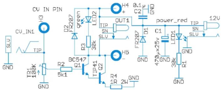
Of course the possibilities of ILLU-MINATOR are not limited to driving LED strips. It can drive many more devices including any types of LEDs that accept 12V, electromagnets, electromotors and more. The ILLU-MINATOR output contains protection diodes that dampen reverse polarity voltage that arises in electromagnets due to self induction. If you are experienced in circuitry, you can use ILLU-MINATOR in much wider applications. For example, the DC supply voltage that feeds ILLU-MINATOR can, in fact, vary from 3 to 20 volts. Peak current for one channel can be up to 5 ampere and average power dissipation on the commutation circuits up to 4 watt per channel. But such modes demand some understanding in engineering. For advanced users, here is the circuit diagram of one channel of ILLU-MINATOR with DC input chain. All 8 channels are identical.
SPECIFICATIONS
| Number of channels. | 8 independent channels |
| Supply voltage | DC 12 V |
| Supply voltage socket | 5.5 x 2.1 mm center plus |
| Output voltage | DC 12 V |
| Output LED socket | 5.5 x 2.1 mm center plus |
| Maximum total power of all channels | 48 watts |
| Maximum total current of all channels | 4 A |
| Recommended maximum current for one channel | 0.5 A |
| Absolute maximum current for one channel | 1.5 A |
| Input voltage range | 3-20 Volts |
| Input impedance | >5.7 kom |
(with correct adjustment of the input sensitivity - 100 kom)
| Input sockets | Eurorack mini-jacks and Pulsar-23/Ornament-8 pins |
| Number of mini-jack sockets. | 8 (1 for each channel) |
| Number of Pulsar-23 pins. | 9 (1 for each channel + 1 common ground) |
| Dimensions | 275x70x40 mm |
| Weight | 300 g |
If you want to use ILLUMINATOR in a permanent setup and avoid connections, you can use special pads that duplicate DC IN and all output sockets. The pads are big and comfortable for soldering and have + - marks. To access these pads remove the top panel.
WHAT'S IN THE KIT:
jkldUMINATOR-1 pc
5.5 x 2.1 mm DC jack—10pcs
Optionally available is a 12V 5A 60W power supply that allows using ILLUMINATOR at maximum power.
Enjoy your music'n'light
connection!
SOMA 2022
Brand : Soma
Model : Illuminator
Category : Uncategorized