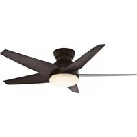
Isotope 59023 - Ceiling fan Casablanca - Free user manual and instructions
Find the device manual for free Isotope 59023 Casablanca in PDF.


| Product Type | Ceiling Fan |
| Brand | Casablanca |
| Model | Isotope 59023 |
| Fan Diameter | 52 inches (132 cm) |
| Motor Type | DC Motor |
| Number of Speeds | 6 speeds |
| Reverse Function | Yes, reversible for summer/winter operation |
| Control Type | Remote control included |
| Light Kit Compatible | Yes, with included LED light kit (dimmable) |
| Blade Material | Engineered wood with walnut finish |
| Mounting Options | Downrod or flush mount, sloped ceiling compatible |
| Input Voltage | 120V AC, 60Hz |
| Motor Wattage | 30 watts (maximum) |
| Airflow (CFM) | 5,200 CFM (high speed) |
| Weight | 18.5 lbs (8.4 kg) |
| Height | 12 inches (30.5 cm) from ceiling with standard downrod |
| Warranty | Limited lifetime motor warranty, 1 year parts |
Frequently Asked Questions - Isotope 59023 Casablanca
User questions about Isotope 59023 Casablanca
0 question about this device. Answer the ones you know or ask your own.
Ask a new question about this device
Download the instructions for your Ceiling fan in PDF format for free! Find your manual Isotope 59023 - Casablanca and take your electronic device back in hand. On this page are published all the documents necessary for the use of your device. Isotope 59023 by Casablanca.
USER MANUAL Isotope 59023 Casablanca
Isotope® Owner's Manual
READ AND SAVE THESE INSTRUCTIONS!
Safety and the proper operation of your Casablanca fan both require a thorough knowledge of the product and proper installation. Therefore, before attempting to install and operate your Casablanca fan, read this Owner's Manual completely and carefully. Retain this manual and other included documentation for future reference.
CAUTION: To avoid possible electrical shock, make certain that electricity is turned off at the circuit breaker or fuse box before attempting any installation procedure.
CONTENTS
INTRODUCTION 3
MOUNTING RECOMMENDATIONS....4
FAN INSTALLATION .... 5
MOTOR HOUSING INSTALLATION....6
BLADE INSTALLATION....10
LIGHT BULB AND GLASS INSTALLATION 11
WALL CONTROL INSTALLATION 12
Your Casablanca fan was crafted with pride and care and inspected thoroughly prior to shipment. Before you begin to assemble and install your Casablanca fan, remove all parts from the carton and check them against the Parts Guide in this manual.
Make sure all parts are included in the box using the Parts Guide on the following pages.
If there are missing or broken parts:
Call 1-888-227-2178 Monday through Friday, 7 a.m. to 4 p.m. Your request will be handled immediately. Replacement parts will be sent to you via Federal Express.
Proper Parts Handling
Do not remove light bulbs from their packaging until you are ready to install them.
Before discarding packaging materials, be certain that all parts have been removed.
Use a clean, dry paintbrush to remove small Styrofoam pieces that may remain after unpacking.
Do not brush Styrofoam into wiring cavities.
The blades in each pack are matched for equal weight to assure smooth fan operation. If more than one fan is being installed, do not mix blades from different cartons.
When cleaning, painting, or working near your fan, be cautious of the fan and blades.
Always turn power to the ceiling fan OFF before replacing light bulbs or working on your fan.
Never insert anything into the path of the fan blades while the fan is in operation.
Never install a fan over a pool or spa.
Never operate a fan that has been damaged in any way.
Install the fan according to the instructions in this manual.
If the fan does not work:
Refer to the Troubleshooting Tips in this Owner's Manual.
Call Technical Support at 1-888-227-2178.
Contact your local Authorized Service Center.
Our Web site at www.CasablancaFanCo.com contains additional information on Casablanca products, troubleshooting, and Authorized Dealer or Service Centers. Please do not return this product to the store.
RECORD MODEL NUMBER BEFORE INSTALLATION!
Please take a moment to locate the model number for your fan (see below) and record this information on the Warranty page inside the front cover of your Owner's Manual if it does not appear there already. The model number is found on the fan identification sticker affixed to the fan under the trim ring in the location shown below:

INTRODUCTION
BEFORE YOU START
- CAUTION: RISK OF ELECTRICAL SHOCK! Installation is to be in accordance with the National Electrical Code, ANSI/NFPA 70-1999, and local codes. If you are unfamiliar with the wiring codes, you should use a qualified electrician. To avoid overheating and possible damage to other equipment, do not install control to a receptacle, fluorescent light fixture, motor-operated appliance, or transformer-supplied appliance.
- This fan is designed to be installed on an existing electrical outlet box. The outlet box must be UL Listed for ceiling fan installations. If it is not, a new box must be installed.
- This ceiling fan requires a grounded electrical supply of 120 VAC, 60 Hz and a minimum 15 amp circuit. The maximum current requirement for the fan with light fixture is 1.67 amps. The fan uses about .83 amp or 100 watts. Maximum light current is about .83 amps or 100 watts of lighting.
- Where wire nuts are employed, be sure all bare wires are within the connectors. When installing the canopy, make sure all wires are within the canopy and that no wires are being pinched.
- WARNING: Do not bend the blade brackets when installing the brackets, balancing the blades, or cleaning the fan. Do not insert foreign objects in between the rotating fan blades.
Unpacking
Before assembling and installing your ceiling fan, remove all parts from the shipping cartons and check them against the parts listed in the Parts Guide. Before discarding packaging materials, be certain that all parts have been removed.
For the best performance and for your warranty to remain valid, use only genuine Casablanca blades, light fixtures, and accessories.
SAFE USE
- The blades in each pack are matched for equal weight to assure smooth fan operation. If more than one fan is being installed, be careful not to mix blades from different cartons.
- Inspect the contents of your carton for possible shipping or handling damage. If parts are missing or damaged, call 1-888-227-2178.
- It is always a good idea to have an assistant to help with the installation.
- When cleaning, painting, or working near your fan, be very careful of the fan and blades. Always turn the power OFF to the ceiling fan before working on it or replacing lightbulbs.
- Never insert anything into the path of the fan blades while the fan is in operation.
- Never install a fan over a pool or spa.
- Never operate a fan that has been damaged in any way. For assistance in obtaining service, call Casablanca Fan Company at 1-888-227-2178 or contact your local authorized Casablanca dealer.
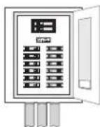
Fuse Box
(Remove fuse for the
circuit you will be
working on)

Circuit Breaker (Trip breaker for the circuit you will be working on)
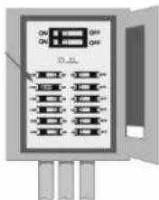

Dimensions indicated are the minimum allowable for proper installation.
MOUNTING RECOMMENDATIONS
GENERAL GUIDELINES
Before mounting your Casablanca fan, read the following helpful recommendations. The location of the fan, air circulation, and fan size are all important factors to consider before installation.
Location
Ceiling fans have practical uses in almost every room in your home. We suggest you follow these mounting recommendations as you decide where to install your Casablanca fan.
- This fan is not suitable for installation on a sloped ceiling.
- For safety reasons, the fan blades must be a minimum of 7' above the floor.
- Do not locate the fan in a doorway or above a swinging door.
- In any installation, the tips of the blades must be at least 18" from the wall in order to provide sufficient clearance for the blades.
- In bedrooms, fans work best when mounted above the foot of the bed.
• Over pool tables, be sure to provide plenty of clearance to avoid damage from pool cues.
- In kitchens be sure to allow for open cupboard doors to clear the fan blades.
- Do not install a fan close to, or over, a pool or spa. High humidity combined with corrosive gases will destroy the finish and warp the blades.
Fan Size
Variable fan speed capability permits the use of a full-size 52" fan even in smaller rooms. For very large rooms, two fans may be needed.


GETTING STARTED
Installing a New Ceiling Fixture Outlet Box
If you do not have an existing fixture located where you wish to place your Casablanca fan, an approved ceiling fixture outlet box must be installed and wired.
WARNING!
To reduce the risk of fire, electrical shock, or personal injury, mount to outlet box marked "Acceptable Fan Support of 31.8 kg (70 lbs.) Or less" using the mounting hardware provided with the outlet box.
Using Existing Ceiling Fixture Outlet Box
After turning the power OFF at its source (either the circuit breaker or fuse box), lower the old fixture and disconnect the wiring. Check the ceiling fixture outlet box to be sure it is marked "Approved for Ceiling Fan Mounting." If it is not, a new box must be installed.
Note: The weight of this fan is 28 pounds.
FAN INSTALLATION
CEILING MOUNTING PLATE INSTALLATION
CEILING HARDWARE (not to scale)

Ceiling Mounting Plate

3" Wood Screws (2) Washers (2)


Wire Nuts (3)
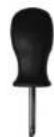
Phillips
Screwdriver
Note: After removing the old fixture, check the outlet box to ensure that it is supported by a joist or beam across its upper surface. If not, a 2 x 4 stud must be installed.
Step 1a. Carefully feed the ceiling wires through the center hole of the ceiling mounting plate. Attach the plate, as shown with ground wire down, to the ceiling fixture outlet box with the screws provided. Ensure that the outlet box wires are not pinched by the washers or between the mounting plate and the ceiling.
Step 1b. Attach the ceiling mounting plate using:
- Wood (included) screws when securing to support structure with approved electrical outlet box. Drill 9/64" pilot holes in support structure to aid in securing ceiling mounting plate with the included hardware.
- Machine screws (provided with the electrical outlet box) when securing to existing ceiling fan-rated outlet box. Make sure it is securely installed and is acceptable for fan support of 31.8 kg (70 lbs) or less.

CAUTION:
To reduce the risk of personal injury, use only the mounting hardware provided with the approved outlet box to install the crossbar mounting plate.
MOTOR HOUSING INSTALLATION
CEILING HARDWARE (not to scale)

Fan Body


Wire Nuts (3) Canopy Screws (4)
Step 2a. Unlock the canopy cover from the canopy ring tabs to loosen and bring down to fan body as shown in Figure 1.
Step 2b. Remove the fan mounting screws from the fan body and set aside. You will use these later.
Step 2d. Use the hanging hole on the body of the fan to hang the fan on the hook of the ceiling mounting plate. This will help you in making the electrical connections as shown in Figure 3 and Figure 4.
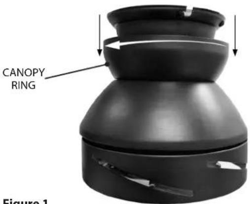
Figure 1
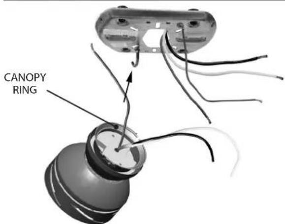
Figure 2

Figure 3
HANGING HOLE
Step 2e. Attach the fan remote wires to the ceiling bracket wiring by placing the bare end of the wires side by side and then securing with a wire nut. Test that the connection is secure by pulling on the wire nut. Connect in this order:
- GREEN leads from ceiling bracket and motor to GROUND conductor of power source. Secure with wire nut as shown in Figure 4.
- WHITE wire from receiver to the WHITE NEUTRAL conductor wire from the power source. Secure with wire nut as shown in Figure 4.
- BLACK wire from receiver to the BLACK conductor wire from the power source. Secure with wire nut as shown in Figure 4.
Step 2f. After making the wire connections, the wires should be tucked into the outlet box. The wires should be spread apart, with the three grounded conductor wires being placed on one side of the fan body and the power conductor wires being placed onto the other side of the fan body separating the connections.
Step 2g. Install two (2) of the canopy screws on the left side of each end of the mounting plate Figure 5.

Figure 4

Figure 5
CANOPY SCREWS
Step 2h. Using both hands, lift the fan body from the hook and position the hanging slots on both sides of the fan body, using the two fan mounting screws located on the ceiling mounting plate. Slide the two slots on both sides of the fan body between the head of the screws and rotate the fan body clockwise into the elongated slots as shown in Figure 6.
Step 2i. Install the other two canopy screws by holding the fan body cover to the ceiling mounting plate as shown in Figure 7 Tighten all four screws until hand tight.
Step 2j. Before going to the next step, locate the two sets of canopy ring tabs that are on the top edge of the canopy as shown in Figure 8. Now locate the two sets of canopy tab holders found at the top of the fan body near the ceiling as shown in Figure 9.

Figure 6

Figure 7

Figure 8

Figure 9
Step 2k. To install the canopy ring you will need to lift straight up on the canopy ring. Lock the CANOPY RING TABS and the CANOPY TAB HOLDERS by rotating the canopy cover clockwise as shown in Figure 10, locking the canopy ring in to place.
Step 21. Check your work by making sure the canopy cover has an even gap between the ceiling and canopy ring as shown in Figure 11.

Figure 10

Figure 11
BLADE INSTALLATION
BLADE HARDWARE (not to scale)

Blades (5)
Blade Screws and Washers (16)
Phillips Screwdriver
Blade Installation
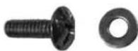
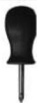
Step 3a. Slide the end of the blade with the three holes into the slot located on the blade ring. (The blades will only fit properly over the screws holes one way. If the holes do not line up, remove the blade and turn it over). Using three blade screws and washers, attach the blade to the blade ring, as shown in Figure 12. Install three screws and washer one by one using the provided screwdriver. Tighten securely by hand only. Repeat until all five blades have been installed on to the fan as shown in Figure 13.
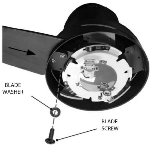
Figure 12
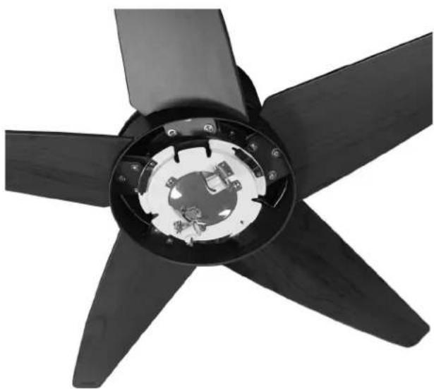
Figure 13
LIGHT BULB AND GLASS INSTALLATION
HARDWARE (not to scale)
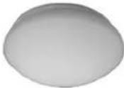
Glass Shade

50 -watt Halogen Bulbs (2)
Install Halogen Bulbs
Step 4. Screw the two bulbs into the light fixture as shown in Figure 14.
IMPORTANT! When installing a halogen bulb, carefully cut off the end of the plastic sleeve the bulb comes in and hold the bulb by the plastic sleeve to screw it into the socket.
NOTE: When replacing the bulbs, be sure to use only 50-watt maximum.
Glass Installation
Step 5a. Align the glass shade up with the bottom of the fan as shown in Figure 15 and locate the three glass holding slots. Then locate the three glass holding tabs, located on the light fixture plate.
Step 5b. Carefully lift the glass globe up inside the light fixture as far as it will go. Rotate the shade in a counter clockwise direction as shown in Figure 16, until the glass globe is held tightly in place by the three tabs.


Figure 15

Figure 16

Wall Control

Cover Plate

Switch Mounting Screws (2)

Cover Plate Screws (2)

(3) Wire Connector
WARNING! To avoid possible electrical shock, make certain that electricity is turned off at the circuit breaker or fuse box before attempting any installation or repair procedure.
CAUTION! NOT turning the power OFF at the circuit breaker or fuse box may cause damage to the electronics within the fan.
Fuse Box
(Remove fuse for the
circuit you will be
working on)

Circuit Breaker (Trip breaker for the circuit you will be working on)
WALL CONTROL INSTALLATION
NOTE: Wall Control should only be installed on Casablanca 5xxxx Series Fans.
This controller is designed to signal the fan's microcomputer as well as perform normal switching operations. For this reason the following precautions must be observed:
- Use only the Casablanca wall control.
- Do not use any additional control with your fan (for example, dimmer, or fan speed control).
WARNING! Ensure power is turned OFF at the breaker or fuse panel before starting installation.
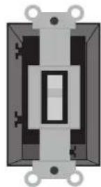
- After removing the switch plate cover, remove all wiring from the switch. Figure 17.
- Using orange wire connectors, connect the two black wires (ungrounded) from the outlet box. Also connect the two green or bare wires (grounding) from the outlet box with the grounding wire from the wall control. Figure 18.
Before
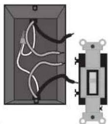
After
Figure 17

Before
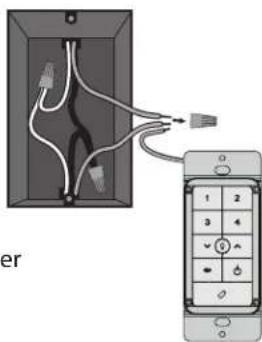
After
Figure 18
- Insert the wall control into the outlet box and secure the two screws using a Phillips head screwdriver. Figure 19.
- Install the cover plate using a Phillips Head screwdriver to secure the two cover plate screws. Figure 20.
WARNING! This device complies with Part 15 of the FCC Rules. Operation is subject to the following conditions: (1) this device may not cause harmful interference, and (2) this device must accept any interference received, including interference that may cause undesired operation.

Figure 19

Figure 20
- Before operating the wall control, press on the battery door to eject it. Unscrew the battery holder. Insert the battery, found in the control hardware bag, with the positive (+) side facing downward. Reinstall the battery holder and reinsert the battery door into the wall control. Figure 21.
- The fan must be paired before it will operate. See Pairing the Remote, page 14.
- Quickly press the up or down arrow to turn the lights off and on. Hold the up or down arrow to raise or dim the light level. The reverse button changes the direction that the blades turn. The power button turns the fan off and on. Figure 23.
- The reverse button on the wall control changes the air flow pattern. In warm weather, use (a) downward air flow pattern. In cold weather, use (b) upward air flow pattern. Figure 23.

Figure 21
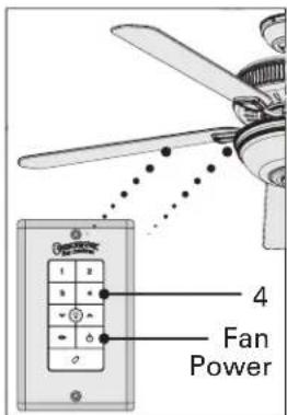
Figure 22

Figure 23
LIGHTS
To turn the lights off and on, press either the up or down arrow.
To adjust the light level, press and hold either the down arrow to dim the light or the up arrow to return the light to full brightness.
Your fan automatically detects what type of bulbs that are installed each time it is powered up. PLEASE NOTE: If CFL bulbs are detected, the dimming function will automatically be disabled. Remember to turn off the lights before replacing bulbs.

Figure 23
PAIRING THE REMOTE
NOTE: The remote must be paired before the fan will operate.
Learning Mode - This feature shall be initiated by cycling the power to the fan. For 3 minutes after cycling power to the fan, the pairing operation can be performed using the wall control.
Begin by pressing both the fan power button and the (4) button for at least 3 seconds. This will send an encoded binary bit message to a target receiver-controller. The fan will turn at the lowest speed signifying that the remote pairing process is complete.
SAFE-EXIT®
The Safe-Exit Program gives you about thirty seconds of light when you turn the lights off, enabling you to exit your home before the lights go out. To enter the Safe-Exit Program:
Incandescent Lighting
- Press the fan power button off for at least three seconds to initiate the Safe-Exit Mode.
- The lights will flash for visual confirmation.
- The lights will stay on 50% brightness for 20 seconds and then begin to dim. After a total of 30 seconds, the lights will be completely off.
CFL Lighting
- Press the fan power button off for at least three seconds to initiate the Safe-Exit Mode.
- The lights will flash for visual confirmation.
- The lights will stay on 100% brightness for 30 seconds. After a total of 30 seconds, the lights will be completely off.
TROUBLESHOOTING TIPS
Please refer to this troubleshooting guide before requesting service or contacting your dealer for assistance.
Fan doesn't work
- Press a fan speed button (1-4).
- Check the circuit breaker to ensure the power is turned on.
- Check the wall control battery.
• Make sure that you have paired the wall control.
• Make sure the blades spin freely.
- Turn off power from the circuit breaker, then check all wire connections according to the wiring instructions.
Excessive wobbling
- Tighten all of the blade and blade iron screws until they are snug.
- Turn the power off, support the fan carefully, and check that the hanger ball is properly seated.
- Use the provided balancing kit and instructions to balance the fan.
Lights do not dim
- Make sure that you do not have a CFL bulb installed. The control has a feature that automatically detects CFL bulbs and turns off dimming if a CFL bulb is installed.
Noisy Operation
- Tighten the blade and blade iron screws until they are snug.
- Check to see if any of the blades are cracked. If so, replace all of the blades.
Lights dim when turned on or do not turn on at all.
- Make sure the wattage of the light bulbs installed matches the specifications on the light sockets.
This device complies with RSS-210 of Industry Canada. Operation is subject to the following two conditions: (1) this device may not cause interference, and (2) this device must accept any interference, including interference that may cause undesired operation of the device.
-
This device complies with part 15 of the FCC Rules. Operation is subject to the following two conditions: (1) this device may not cause harmful interference, and (2) this device must accept any interference received, including interference that may cause undesired operation.
-
This equipment has been tested and found to comply with the limits for a Class B digital device, pursuant to Part 15 of the FCC Rules. These limits are designed to provide reasonable protection against harmful interference in a residential installation. This equipment generates, uses and can radiate radio frequency energy and, if not installed and used in accordance with the instructions, may cause harmful interference to radio communications. However there is no guarantee that interference will not occur in a particular installation. If this equipment does cause harmful interference to radio or television reception, which can be determined by turning the equipment off and on, the user is encouraged to try to correct the interference by one or more of the following measures: Reorient or relocate the receiving antenna, Increase the separation between the equipment and receiver, Connect the equipment into an outlet on a circuit different from that to which the receiver is connected. Consult the dealer or an experienced radio/TV technician for help. Note: Any changes or modifications to the transmitter or receiver not expressly approved by Casablanca Fan Company may void one's authority to operate this remote control.
CARE RECOMMENDATIONS
Fan Finishes
- For cleaning, a soft brush or lint-free cloth should be used to prevent scratching the finish.
- A vacuum cleaner brush nozzle can remove heavier dust.
- Surface smudges or an accumulation of dirt and dust can be removed easily using a mild detergent and slightly dampened soft cloth. An antistatic agent may be used, but never use abrasive cleaning agents as these will damage the finish.
Blades
- Wood-finish blades should be cleaned with a furniture polishing cloth. Occasionally, a light coat of furniture polish may be applied for added protection and luster.
- For painted and high-gloss blades, surface smudges or an accumulation of dirt and dust can be removed easily using a mild detergent and slightly dampened soft cloth. An antistatic agent may be used, but never use abrasive cleaning agents as these will damage the finish.
- Warning: To reduce the risk of personal injury, do not bend the blade brackets when installing the brackets, balancing the blades, or cleaning the fan. Do not insert foreign objects in between rotating fan blades.
No Need for Lubrication
- Never lubricate this fan! The precision motor at the heart of your Casablanca fan features sealed bearings that are lubricated for life.
- Do not attempt to oil the motor.
Changing Lightbulbs
- Be sure to turn the power to OFF at the wall switch or circuit breaker before changing lightbulbs.
- Replace bulbs with the same type as you removed from the light fixture.
- The maximum wattage rating for this fan's light kit is 100 watts for the light.
For questions or to locate the nearest Casablanca Authorized Service Center, call toll-free 1-888-227-2178 or visit us at www.CasablancaFanCo.com
This device complies with RSS-210 of Industry Canada. Operation is subject to the following two conditions: (1) this device may not cause interference, and (2) this device must accept any interference, including interference that may cause undesired operation of the device.
-
This device complies with part 15 of the FCC Rules. Operation is subject to the following two conditions: (1) this device may not cause harmful interference, and (2) this device must accept any interference received, including interference that may cause undesired operation.
-
This equipment has been tested and found to comply with the limits for a Class B digital device, pursuant to Part 15 of the FCC Rules. These limits are designed to provide reasonable protection against harmful interference in a residential installation. This equipment generates, uses and can radiate radio frequency energy and, if not installed and used in accordance with the instructions, may cause harmful interference to radio communications. However there is no guarantee that interference will not occur in a particular installation. If this equipment does cause harmful interference to radio or television reception, which can be determined by turning the equipment off and on, the user is encouraged to try to correct the interference by one or more of the following measures: Reorient or relocate the receiving antenna, Increase the separation between the equipment and receiver, Connect the equipment into an outlet on a circuit different from that to which the receiver is connected. Consult the dealer or an experienced radio/TV technician for help. Note: Any changes or modifications to the transmitter or receiver not expressly approved by Casablanca Fan Company may void one's authority to operate this remote control.
- ISOTOPE® OWNER'S MANUAL
- READ AND SAVE THESE INSTRUCTIONS
- CONTENTS
- MAKE SURE ALL PARTS ARE INCLUDED IN THE BOX USING THE PARTS GUIDE ON THE FOLLOWING PAGES
- PROPER PARTS HANDLING
- INSTALL THE FAN ACCORDING TO THE INSTRUCTIONS IN THIS MANUAL
- RECORD MODEL NUMBER BEFORE INSTALLATION
- INTRODUCTION
- BEFORE YOU START
- UNPACKING
- SAFE USE
- MOUNTING RECOMMENDATIONS
- GENERAL GUIDELINES
- LOCATION
- FAN SIZE
- GETTING STARTED
- INSTALLING A NEW CEILING FIXTURE OUTLET BOX
- WARNING
- USING EXISTING CEILING FIXTURE OUTLET BOX
- FAN INSTALLATION
- CEILING MOUNTING PLATE INSTALLATION
- CAUTION
- MOTOR HOUSING INSTALLATION
- BLADE INSTALLATION
- LIGHT BULB AND GLASS INSTALLATION
- INSTALL HALOGEN BULBS
- GLASS INSTALLATION
- WALL CONTROL INSTALLATION
- WARNING! ENSURE POWER IS TURNED OFF AT THE BREAKER OR FUSE PANEL BEFORE STARTING INSTALLATION
- LIGHTS
- PAIRING THE REMOTE
- SAFE-EXIT®
- TROUBLESHOOTING TIPS
- FAN DOESN'T WORK
- EXCESSIVE WOBBLING
- LIGHTS DO NOT DIM
- NOISY OPERATION
- LIGHTS DIM WHEN TURNED ON OR DO NOT TURN ON AT ALL
- CARE RECOMMENDATIONS
- FAN FINISHES
- BLADES
- NO NEED FOR LUBRICATION
- CHANGING LIGHTBULBS
- FOR QUESTIONS OR TO LOCATE THE NEAREST CASABLANCA AUTHORIZED SERVICE CENTER, CALL TOLL-FREE 1-888-227-2178 OR VISIT US AT WWW.CASABLANCAFANCO.COM
Brand : Casablanca
Model : Isotope 59023
Category : Ceiling fan