
HWS1600D - Measurement Dahua Technology - Free user manual and instructions
Find the device manual for free HWS1600D Dahua Technology in PDF.


| Product Type | Laser Distance Measurer |
| Model | HWS1600D |
| Brand | Dahua Technology |
| Measurement Range | Up to 40 m |
| Measurement Accuracy | ±2 mm |
| Laser Class | Class 2 (IEC 60825-1) |
| Power Supply | 2 x AAA batteries (1.5V) |
| Dimensions (L x W x H) | 120 x 50 x 30 mm |
| Weight | 150 g (including batteries) |
| Measurement Functions | Distance, area, volume, continuous measurement, indirect Pythagoras |
| Display | Backlit LCD with 4 rows |
| Units | m, ft, in, ± |
| Memory | Last 10 measurements |
| Auto Power Off | After 3 minutes of inactivity |
| Water Resistance | IP54 (splash proof) |
| Operating Temperature | 0°C to 40°C |
| Storage Temperature | -20°C to 60°C |
| Maintenance | Clean lens with soft, dry cloth; avoid solvents |
| Safety Precautions | Do not stare into laser beam; avoid eye exposure |
| Spare Parts | Batteries (AAA), carrying case |
| Repairability | Battery compartment user-replaceable; other repairs by authorized service |
| General Information | Compact design for indoor and outdoor use; includes belt clip |
Frequently Asked Questions - HWS1600D Dahua Technology
User questions about HWS1600D Dahua Technology
0 question about this device. Answer the ones you know or ask your own.
Ask a new question about this device
Download the instructions for your Measurement in PDF format for free! Find your manual HWS1600D - Dahua Technology and take your electronic device back in hand. On this page are published all the documents necessary for the use of your device. HWS1600D by Dahua Technology.
USER MANUAL HWS1600D Dahua Technology
Speed Measuring Device
User's Manual

natural_image
Abstract geometric composition with gray and red color blocks (no text or symbols)Foreword
General
This manual introduces the basic information, functions, and operations of the speed measuring device (hereinafter referred to as "the Device"). Read carefully before using the Device, and keep the manual safe for future reference.
Model
DHI-HWS1600D
Safety Instructions
The following signal words might appear in the manual.
| Signal Words Meaning | ||
 | DANGER | Indicates a high potential hazard which, if not avoided, will result in death or serious injury. |
 | WARNING | Indicates a medium or low potential hazard which, if not avoided, could result in slight or moderate injury. |
 | CAUTION | Indicates a potential risk which, if not avoided, could result in property damage, data loss, reductions in performance, or unpredictable results. |
 | TIPS Provides methods to help you solve a problem or save time. | |
 | NOTE | Provides additional information as a supplement to the text. |
Revision History
| Version | Revision Content | Release Time |
| V1.0.0 | First release. | August 2022 |
Privacy Protection Notice
As the device user or data controller, you might collect the personal data of others such as their face, fingerprints, and license plate number. You need to be in compliance with your local privacy protection laws and regulations to protect the legitimate rights and interests of other people by implementing measures which include but are not limited: Providing clear and visible identification to inform people of the existence of the surveillance area and provide required contact information.
About the Manual
- The manual is for reference only. Slight differences might be found between the manual and the product.
- We are not liable for losses incurred due to operating the product in ways that are not in compliance with the manual.
- The manual will be updated according to the latest laws and regulations of related jurisdictions.
For detailed information, see the paper user's manual, use our CD-ROM, scan the QR code or visit our official website. The manual is for reference only. Slight differences might be found between the electronic version and the paper version.
- All designs and software are subject to change without prior written notice. Product updates might result in some differences appearing between the actual product and the manual. Please contact customer service for the latest program and supplementary documentation.
- There might be errors in the print or deviations in the description of the functions, operations and technical data. If there is any doubt or dispute, we reserve the right of final explanation.
- Upgrade the reader software or try other mainstream reader software if the manual (in PDF format) cannot be opened.
- All trademarks, registered trademarks and company names in the manual are properties of their respective owners.
- Please visit our website, contact the supplier or customer service if any problems occur while using the device.
- If there is any uncertainty or controversy, we reserve the right of final explanation.
Important Safeguards and Warnings
This section introduces content covering the proper handling of the Device, hazard prevention, and prevention of property damage. Read carefully before using the Device, and comply with the guidelines when using it.
Transportation Requirements

- Pack the Device with packaging provided by its manufacturer or packaging of the same quality before transporting it.
- Transport the Device under allowed humidity and temperature conditions.
Storage Requirements

Store the Device under allowed humidity and temperature conditions.
Installation Requirements

WARNING
- Do not connect the power adapter to the Device while the adapter is powered on.
- Strictly comply with the local electric safety code and standards. Make sure that the ambient voltage is stable and meets the power supply requirements of the Device.
- Do not connect the Device to 2 or more kinds of power supplies, to avoid damage to the Device.
- Use the accessories suggested by the manufacturer. Installation and maintenance must be performed by qualified professionals.
- When using a laser beam device, avoid exposing the surface of the Device to laser beam radiation.
- Do not install the Device in an environment that has a large amount of metal, advertising boards, walls or electromagnetic interference. Otherwise, the performance of the Device might be affected
- Do not install 2 devices with the same frequency in the same environment. Otherwise, the Device might not work properly.

- Personnel working at heights must take all necessary measures to ensure personal safety including wearing a helmet and a safety belt.
- Do not place the Device in a place exposed to sunlight or near heat sources.
- Keep the Device away from dampness, dust, and soot.
- Put the Device in a well-ventilated place, and do not block its ventilation.
- Use an adapter or cabinet power supply provided by the manufacturer.
- The power supply must conform to the requirements of ES1 in IEC 62368-1 standard and be no higher than PS2. Please note that the power supply requirements are subject to the device label.
- The Device is a class I electrical appliance. Make sure that the power supply of the Device is
connected to a power socket with protective earthing.
- An emergency disconnect device must be installed during installation and wiring at a readily accessible location for emergency power cut-off.
- Protect the line cord and wires from being walked on or squeezed particularly at plugs, power sockets, and the point where they exit from the device.
- Make sure that the Device is installed horizontally, and that there are no items blocking the front of the Device.
Operation Requirements
!
- Check whether the power supply is correct before use.
- Do not unplug the power cord on the side of the Device while the adapter is powered on.
- Operate the Device within the rated range of power input and output.
- Use the Device under allowed humidity and temperature conditions.
- Do not drop or splash liquid onto the Device, and make sure that there is no object filled with liquid on the Device to prevent liquid from flowing into it.
- Do not disassemble the Device without professional instruction.
- Please do not touch the photosensitive device with your hands. Use an air blower to clean off the dust and filth on the lens.
- We recommend you use the Device with a lightning protection device for stronger protection against lightning. For outdoor scenarios, strictly comply with the lightning protection regulations.
- Ground the function earthing portion of the Device to improve its reliability. The Device is a class I electrical appliance. Make sure that the power supply of the Device is connected to a power socket with protective earthing.
- Charge the lithium battery with a standard adapter.
- We recommend you pull out the battery after use to avoid excessive battery consumption.
Maintenance Requirements
!
- Clean the Device with a soft dry cloth or a clean soft cloth dipped in neutral detergent.
- Use the accessories suggested by the manufacturer. Installation and maintenance must be performed by qualified professionals.
Table of Contents
Foreword ....
Important Safeguards and Warnings....III
1 Product Information .... 1
1.1 Introduction ...... 1
1.2 Main Functions.... 1
2 Structure....3
2.1 Appearance....3
2.2 Dimensions....3
2.3 Panels 4
2.3.1 Left Panel 4
2.3.2 Right Panel 5
2.3.3 Front Panel....5
3 GUI Operations....7
3.1 Introduction ......7
3.1.1 Login 7
3.1.2 Main Interface....7
3.2 Live Snapshot....8
3.2.1 Live 8
3.2.2 Snapshot....10
3.3 Image Manager....11
3.3.1 Search....11
3.3.2 Backup....13
3.4 Config....13
3.4.1 Intelligent Plan....13
3.5 Manage Info....35
3.5.1 System Info....35
3.5.2 Log Search 35
3.5.3 User Manager....36
3.5.4 Traffic Flow Statistics....37
4 Webpage Operations....39
4.1 Introduction ......39
4.1.1 Initialization....39
4.1.2 Webpage Functions....42
4.2 Live....43
4.2.1 Video Stream....43
4.2.2 Live View....44
4.2.3 Plate Number Recognition....45
4.2.4 Plate Snapshot....45
4.2.5 Functions on the Live Page 45
4.2.6 Vehicle Snapshot....46
4.2.7 Event List....46
4.3 Radar 46
4.3.1 Radar Settings 46
4.3.1.1 Calibrating the Radar....46
4.3.1.2 Configuring General Information....47
4.3.2 Radar Visualization....48
4.4 Search....49
4.4.1 Searching for Vehicles....49
4.4.2 Searching for Recorded Videos ....51
4.5 Setting....52
4.5.1 ITC....52
4.5.1.1 Smart Plan....52
4.5.1.2 ANPR Snapshot....53
4.5.1.2.1 Configuring Violation Snapshot....53
4.5.1.2.2 Configuring Intelligent Analysis ....59
4.5.1.2.3 Configuring Original Picture OSD 61
4.5.1.2.4 Configuring Combination Picture OSD 62
4.5.1.2.5 Configuring Cutout....62
4.5.1.3 E Police....62
4.5.1.3.1 Configuring Violation Snapshot....62
4.5.1.3.2 Configuring Intelligent Analysis 69
4.5.1.3.3 Configuring Original Picture OSD 71
4.5.1.3.4 Configuring Combination Picture OSD 72
4.5.1.3.5 Configuring Cutout....73
4.5.1.4 Composition & OSD....73
4.5.1.4.1 Configuring Picture Synthesis 73
4.5.1.4.2 Configuring Video OSD....74
4.5.1.5 Transfer Offline....75
4.5.1.6 Vehicle Allowlist/Blocklist....76
4.5.1.6.1 Setting Allowlist....76
4.5.1.6.2 Setting Blocklist....77
4.5.1.7 Traffic Flow....77
4.5.1.8 Watermark....78
4.5.1.8.1 Verifying Images ....78
4.5.1.8.2 Verifying Videos ....78
4.5.2 Camera....79
4.5.2.1 Image....79
4.5.2.1.1 Configuring General Parameters 79
4.5.2.1.2 Configuring Shutter....80
4.5.2.1.3 Configuring Metering Zone 82
4.5.2.2 Video....83
4.5.2.2.1 Configuring Video Parameters ....83
4.5.2.2.2 Configuring ROI....84
4.5.3 Network Settings 85
4.5.3.1 Configuring TCP/IP....85
4.5.3.2 Port....87
4.5.3.2.1 Configuring Port....87
4.5.3.2.2 Configuring ONVIF....87
4.5.3.2.3 Configuring Auto Registration 88
4.5.3.2.4 Configuring 802.1x....88
4.5.4 Event......89
4.5.4.1 Exception....89
4.5.4.2 Device Location 90
4.5.5 Peripheral....90
4.5.5.1 Device Status....90
4.5.5.2 External Light....90
4.5.6 Storage....91
4.5.6.1 Storage Spot Config 91
4.5.6.2 Local Storage 92
4.5.6.3 FTP....92
4.5.6.4 Storage Path....94
4.5.6.5 SMART....94
4.5.7 Record....94
4.5.7.1 Record Control 94
4.5.7.2 Schedule....95
4.5.8 System....96
4.5.8.1 General....96
4.5.8.1.1 General Settings 96
4.5.8.1.2 Date & Time....97
4.5.8.2 Account Management....98
4.5.8.2.1 Account....98
4.5.8.2.2 ONVIF User....99
4.5.8.3 Security 100
4.5.8.3.1 System Service....100
4.5.8.3.2 HTTPS....102
4.5.8.3.3 Firewall....104
4.5.8.4 Default....105
4.5.8.5 Import/Export....105
4.5.8.6 Maintainance Configuration 105
4.5.8.6.1 Maintenance....105
4.5.8.6.2 Emergency Maintenance....106
4.5.8.7 Update....106
4.5.9 System Information....106
4.5.9.1 Version Information 106
4.5.9.2 Log....107
4.5.9.2.1 System Log.... 107
4.5.9.2.2 Remote Log....107
4.5.9.3 Online User....108
4.5.9.4 Running Status....108
4.5.9.5 Legal Information 108
4.6 Alarm 108
Appendix 1 Cybersecurity Recommendations ...... 110
1 Product Information
1.1 Introduction
The Device adopts a fully embedded system with functions such as vehicle speed measurement, image capture, video surveillance, and automatic recognition of license plate number, lane, color, and vehicle model. Compared with traditional radar systems that separate industrial PC and IP camera, the Device combines the company's technical advantages in intelligent traffic field to provide you with stable performance, powerful functions, and ease of installation.
1.2 Main Functions
Image Composition
Supports the composition of 4 images at most.
OSD Information
Supports various OSD information such as time, location, lane information, license plate information, vehicle information, speed limit, road direction, capture direction, event information, and GPS coordinates.
Lane Monitoring
Monitors up to 4 lanes.
GPS/BeiDou Positioning
Supports GPS/BeiDou positioning.
WiFi Connection
Supports connection to a Wi-Fi network.
Time Synchronization
Supports NTP/GPS/BeiDou time synchronization and synchronization with PC time.
Storage
● Supports local storage and FTP.
- Supports setting the storage quota of images and videos.
Radar Visualization
● Supports configuring lane width and the installation parameters of the radar.
● Supports displaying the tracing effects and real-time videos.
Radar Calibration
Supports calibrating the radar based on radar and video data, which realizes the auto configuration of lane width and the installation parameters of the radar.
GUI Operations
Supports GUI operations.
2 Structure
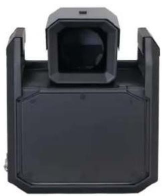
2.1 Appearance
Figure 2-1 Device appearance
natural_image
Black plastic mechanical component with a central square aperture and side brackets (no text or symbols visible)2.2 Dimensions
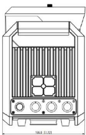
Figure 2-2 Dimensions (mm [inch])
![280.2 111.30 280.9 [4.37]](/content/2026/05/1042354/images/99aa9ebbc1e1240c14f4612129bf0e112898ddf95886ec0083ec0aa87186275b.jpg)
natural_image
Technical line drawing of a mechanical or electrical enclosure with internal components and mounting holes (no text or symbols)2.3 Panels
2.3.1 Left Panel
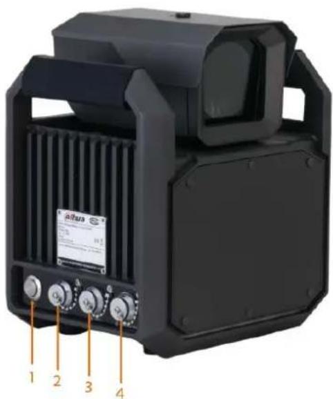
Figure 2-3 Left panel
natural_image
Exterior view of a black industrial device with labeled ports and panel (no readable text or symbols)Table 2-1 Port description
| No. Description | |
| 1 Power switch | |
| 2 24 VDC power input port | |
| 3 Ethernet port and USB port | |
| 4 | RS-232 port and RS-485 port |
2.3.2 Right Panel
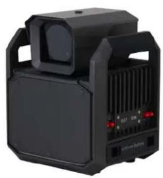
Figure 2-4 Right panel
natural_image
Black industrial electronic device with ventilation grilles and control buttons (no visible text or symbols)2.3.3 Front Panel
Figure 2-5 Front panel
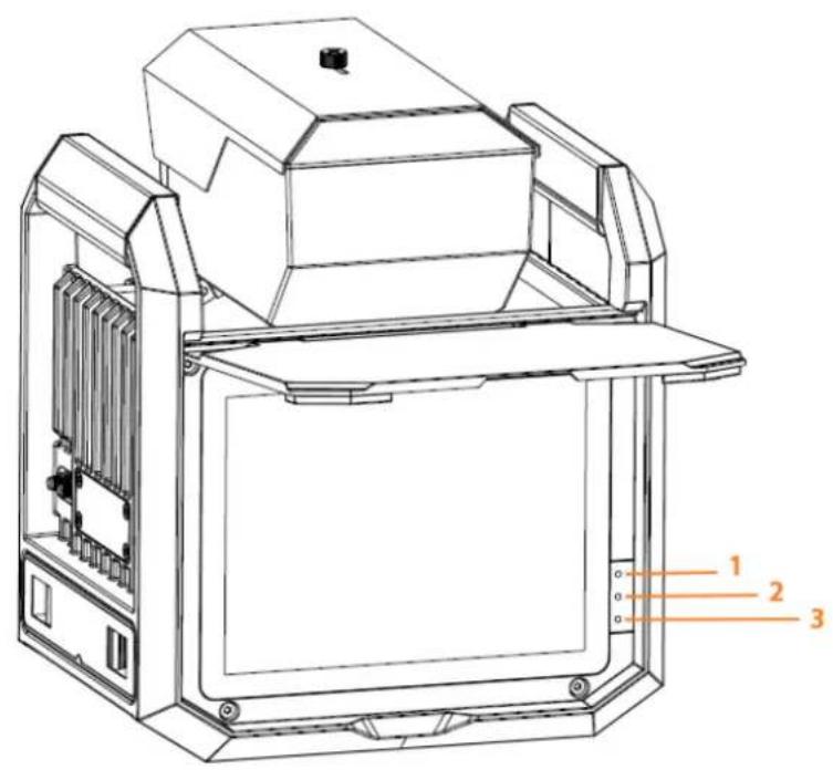
Table 2-2 Indicator light description
| No. | Icon | Color | Function |
| 1 Blue |  | Flashing: The lithium battery is being recharged.On: The recharge is completed.Off: The lithium battery is not being recharged. | |
| 2 Green |  | Flashing: The Device runs normally.Off: The Device stops working. | |
| 3 |  | Red | On: The Device is on.Off: The Device is off. |
3 GUI Operations
After you install the Device, you can set parameters on the graphic user interface (GUI) of the Device.
3.1 Introduction
3.1.1 Login
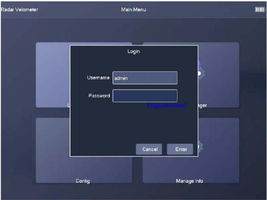
Step 1 Start the Device after it is installed and all wires are connected.
The Login dialog box appears.
Step 2 In the Login dialog box, enter the username and password, and then tapEnter.
Figure 3-1 Login
3.1.2 Main Interface
The main interface of the GUI includes 4 parts: Live Snapshot, Image Manager, Config, and Manage Info.
Figure 3-2 Main interface
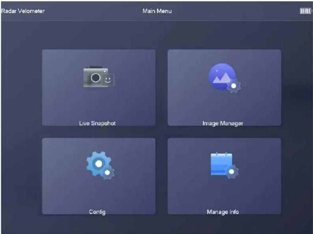
- Live Snapshot: You can view real-time video and captured images, rotate the PTZ, and configure the parameters of zoom & focus and image display.
• Image Manager: You can search for and back up captured images. - Config: You can configure various parameters of the Device.
- Manage Info: You can view system information, manage users, and search for logs and traffic flow data.
3.2 Live Snapshot
3.2.1 Live
Tap Live Snapshot on the main interface, and theLive tab appears.
Figure 3-3 Live
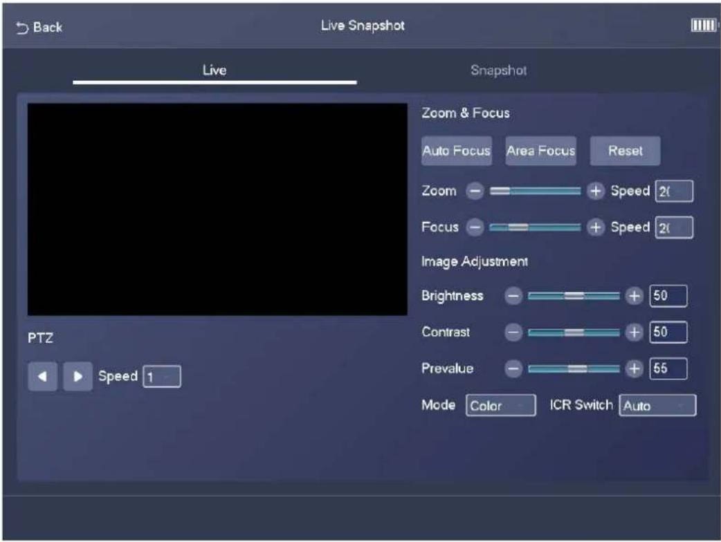
Table 3-1 Parameters on the Live tab
| Module Parameter Description | ||
| PTZ Speed | The speed at which the PTZ moves.Click or to make the PTZ horizontally move to the left or right. | |
| Zoom & Focus | Auto Focus | After you tap the icon, the system automatically focuses the camera. |
| Area Focus | After you tap the icon and select an area on the video, the system focuses the camera for the selected area. | |
| Reset | After you tap the icon, the system resets zoom and focus parameters. | |
| Image Adjustment | Brightness | The brightness of the image. |
| Contrast | The contrast of the image. | |
| Prevalue | The preset value of brightness. | |
| Mode | Color: The image is always colored.Auto: When the brightness is higher than the preset value, the image automatically changes to color. When it is below the preset value, the image changes to black and white.B/W: The image is always black and white. | |
| ICR SwitchAuto: You need to pre-set the brightness in this mode. When the ambient brightness is higher than the preset value, the polarizer will start to work.Polarizer: The polarizer is always running. Applicable to scenarios with high brightness.IR Mode: Applicable to scenarios with low brightness. | ||
3.2.2 Snapshot
Tap Live Snapshot on the main interface, and then tap Snapshot. The Snapshot tab displays snapshots and related information including date, plate number, vehicle speed, vehicle type, lane number, and the number of snapshots on the current day.
Figure 3-4 Snapshot
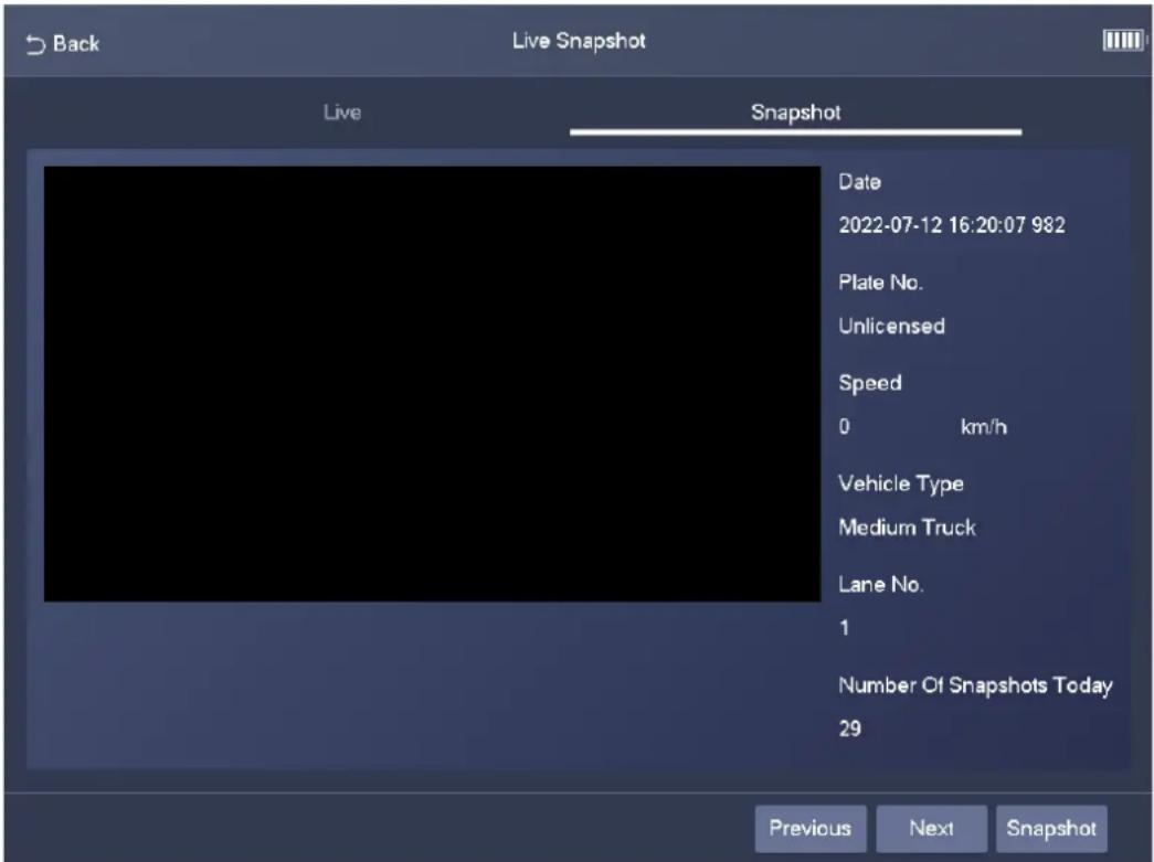

- Tap Previous to view the previous snapshot.
- Tap Next to view the next snapshot.
- Tap Snapshot to take a snapshot.
3.3 Image Manager
3.3.1 Search
Step 1 Tap Image Manager on the main interface, and then the Search tab appears.
Figure 3-5 Search
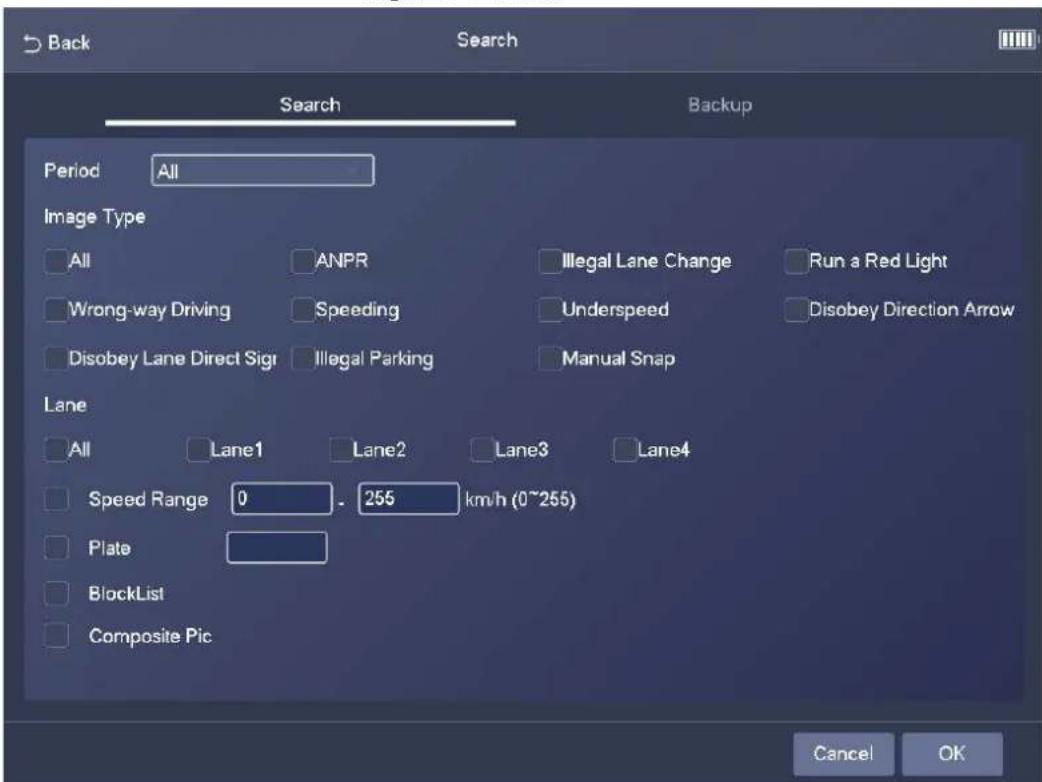
Step 2 Set filter conditions, including period, image type, lane number, speed range, and plate number.
Step 3 Select BlockList and Composite Pic as needed, and then tap OK. The search results are displayed in a list.
Figure 3-6 Search results
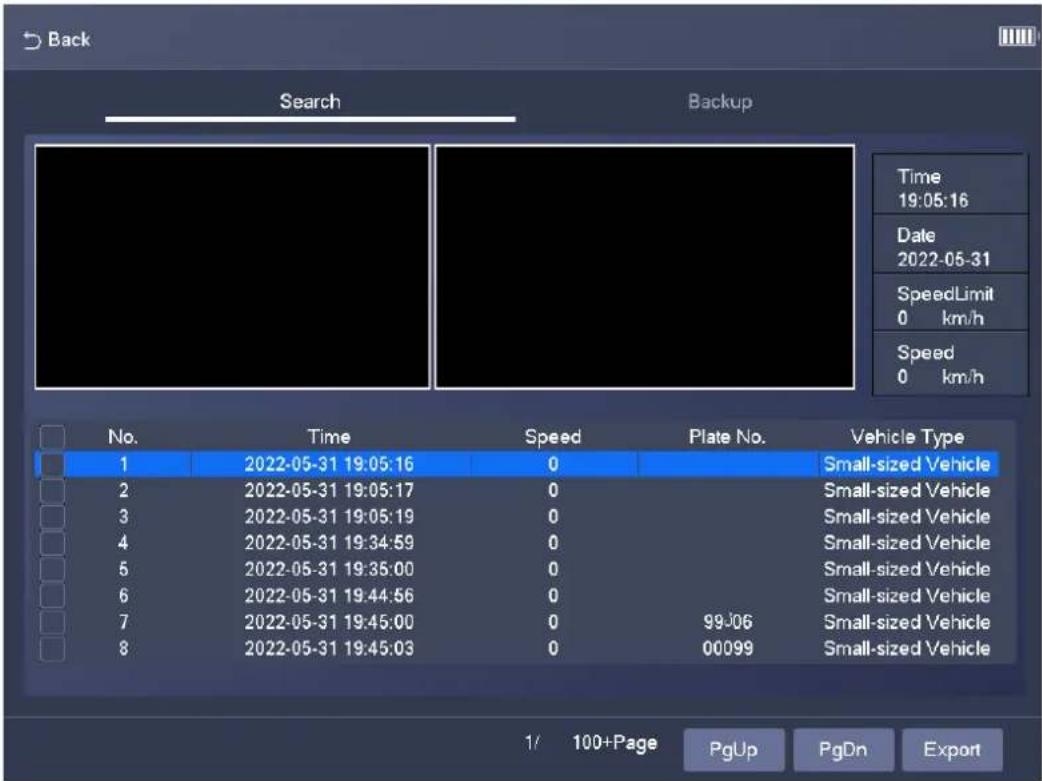
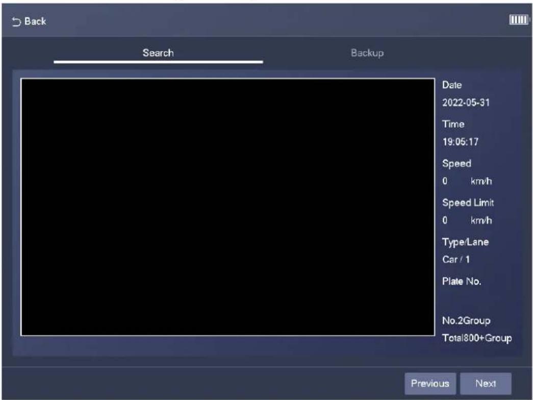
Step 4 Tap a search result, and then the related image and its information are displayed.
Figure 3-7 Image details
3.3.2 Backup
Step 1 Tap Image Manager on the main interface, and then tap Backup.
Figure 3-8 Backup
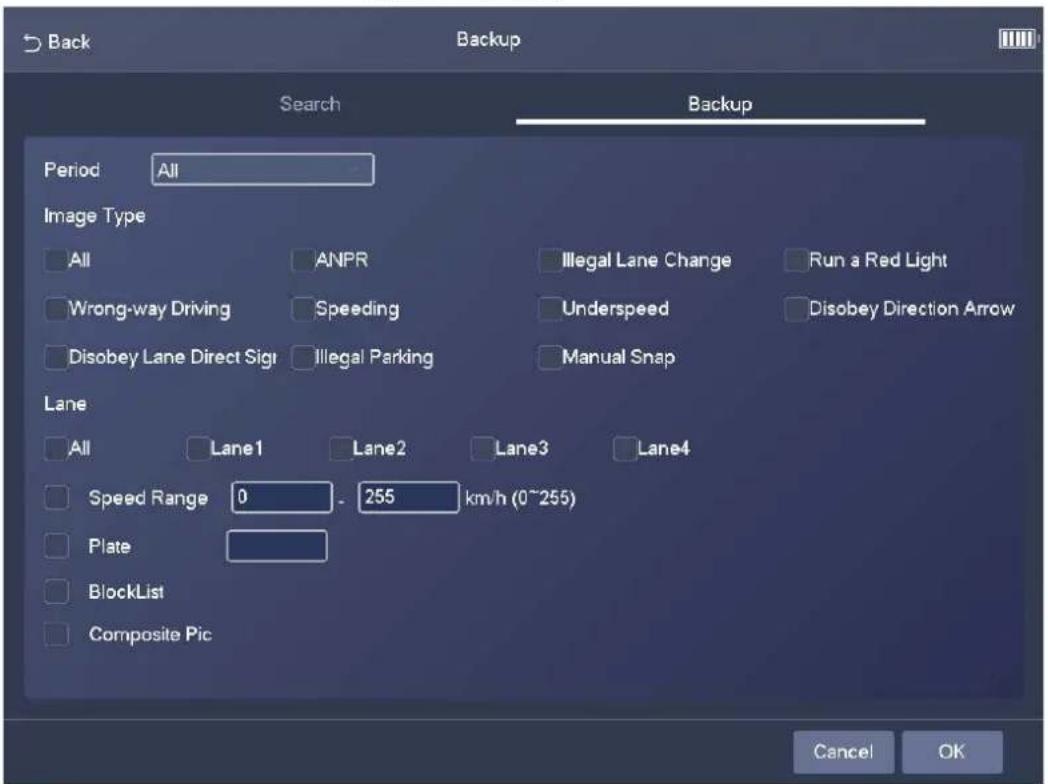
Step 2 Set filter conditions, including period, image type, lane number, speed range, and plate number.
Step 3 Select BlockList and Composite Pic as needed, and then tap OK. The images that meet the filter conditions are backed up.
3.4 Config
Step 2 Configure the parameters.
Table 3-2 Description of ANPR parameters
| Parameter Description | |
| ANPR Enable | Specifies whether to enable the ANPR mode. |
| Snap Mosaic | Specifies whether to enable image mosaic. |
| IFS The frame interval of capturing 2 images. | |
Step 3 Enable traffic rules for different lanes, and then tap Save.
3.4.1.2 E-police
Step 1 Select Config > Intelligent Plan > E-police.
Figure 3-10 E-police
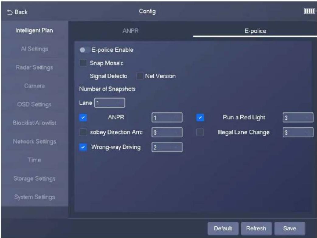
Step 2 Configure the parameters.
Table 3-3 Description of E-police parameters
| Parameter Description | |
| E-police Enable | Specifies whether to enable E-police mode. |
| Snap Mosaic | Specifies whether to enable image mosaic. |
| Signal Detector | SelectNet Versionto enable the light connected through the network. |
Step 3 Enable rules for different lanes, and then tap OK.
3.4.2 AI Settings
3.4.2.1 Scene Config
Step 1 Select Config > AI Settings > Scene Config.
Step 2 Select a lane for which you want to draw lines or regions.
Figure 3-11 Scene config
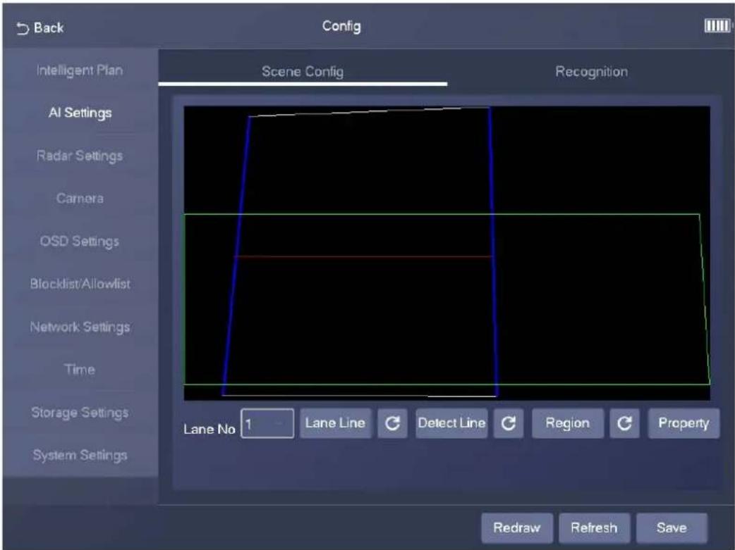
- Tap Lane Line, and then draw a lane line.
- Tap Detect Line, and then draw a detection line.
- Tap Region, and then draw a region.
- Tap G to delete the lines or regions you have drawn.
Step 3 Tap Save.
3.4.2.2 Recognition
Step 1 Select Config > AI Settings > Recognition.
Step 2 Configure the parameters.
Figure 3-12 Recognition
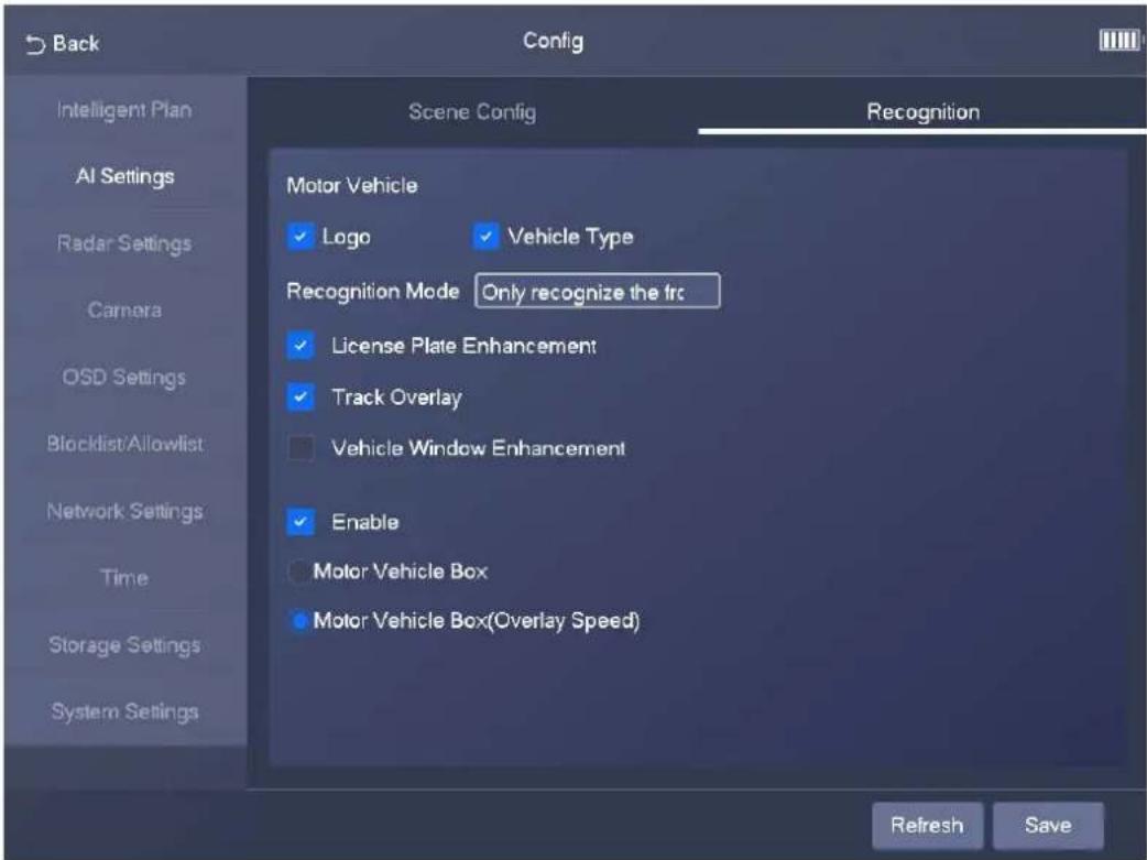
Table 3-4 Description of recognition parameters
| Parameter Description | |
| Motor Vehicle | Supports recognizing vehicle logs and vehicle types. |
| License Plate Enhancement | Select the checkbox to enhance the effect of license plate images. |
| Vehicle Window Enhancement | Select the checkbox to enhance the effect of vehicle window images. |
| Track Overlay Select the checkbox to enable Track Overlay. | |
| Recognition Mode | Only recognize the front plate: Recognizes and captures the license plate on the vehicle head.Only recognize the rear plate: Recognizes and captures the license plate on the vehicle rear.Front plate priority: Head plate has the priority.Rear plate priority: Rear plate has the priority. |
3.4.3 Radar Settings
3.4.3.1 Parameters
Step 1 Select Config > Radar Settings > Parameters.
Figure 3-13 Parameters
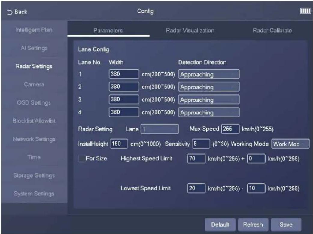
Step 2 Configure the parameters.
Table 3-5 Description of radar parameters
| Parameter Description | |
| Width The width of the lane. | |
| Detection Direction | The driving direction that triggers detection. |
| Max Speed | The maximum vehicle speed that can be recognized by the radar. |
| InstallHeight | The installation height of the Device. |
| Working Mode | Work Mode: Use this mode in actual situation.Soak Mode: Use this mode for product certification. |
| For Size | After you select the checkbox, the Device can distinguish large vehicles from small vehicles. |
| Highest Speed Limit | The allowed highest vehicle speed. If a vehicle runs over the highest speed, the vehicle is overspeed. |
| Lowest Speed Limit | The lowest vehicle speed. If a vehicle runs below the lowest speed, the vehicle is underspeed. |
Step 3 Tap Save.
3.4.3.2 Radar Visualization
On the Radar Visualization tab, you can view the effect of radar detection in real time and modify some of the radar parameters.
Step 1 Select Config > Radar Settings > Radar Visualization.
Step 2 Adjust the value of angle correction and horizontal offset.
Figure 3-14 Radar visualization
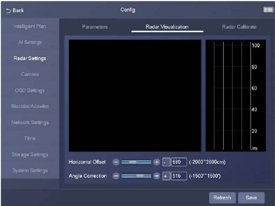
Step 3 Tap Save.
3.4.3.3 Radar Calibration
Make sure that the camera can capture right targets when the radar sends signals to the camera.

Radar calibration on the GUI is similar to that on the webpage. For details on radar calibration, see "4.3.1.1 Calibrating the Radar".
Step 1 Select Config > Radar Settings > Radar Calibrate.
Step 2 Set Area Width to the width of the actual road.
After you set the width of the calibration area to the width of the actual road, the algorithm will automatically calibrate the radar.
Step 3 Tap Save.
3.4.4 Camera
3.4.4.1 Shutter
You can configure shutter mode, exposure mode, and gain mode.
Step 1 Select Config > Camera > Shutter.
Figure 3-15 Shutter
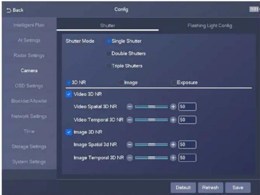
Step 2 Configure the parameters.
Shutter parameters on the GUI are similar to those on the webpage. For details, see Table 4-30.
Step 3 Tap Save.
3.4.4.2 Flashing Light Config
You can configure the work mode of the flashing lights and strobes connected to the Device.
Step 1 Select Config > Camera > Flashing Light Config
Figure 3-16 Flashing light config
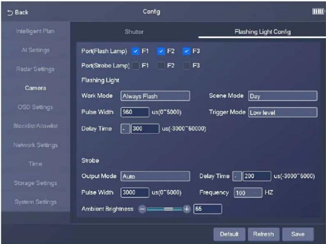
Step 2 Configure the parameters.
Flashing light parameters on the GUI are similar to those on the webpage. For details on flashing light parameters, see Table 4-37.
Step 3 Tap Save.
3.4.5 OSD Settings
3.4.5.1 OSD Road Section
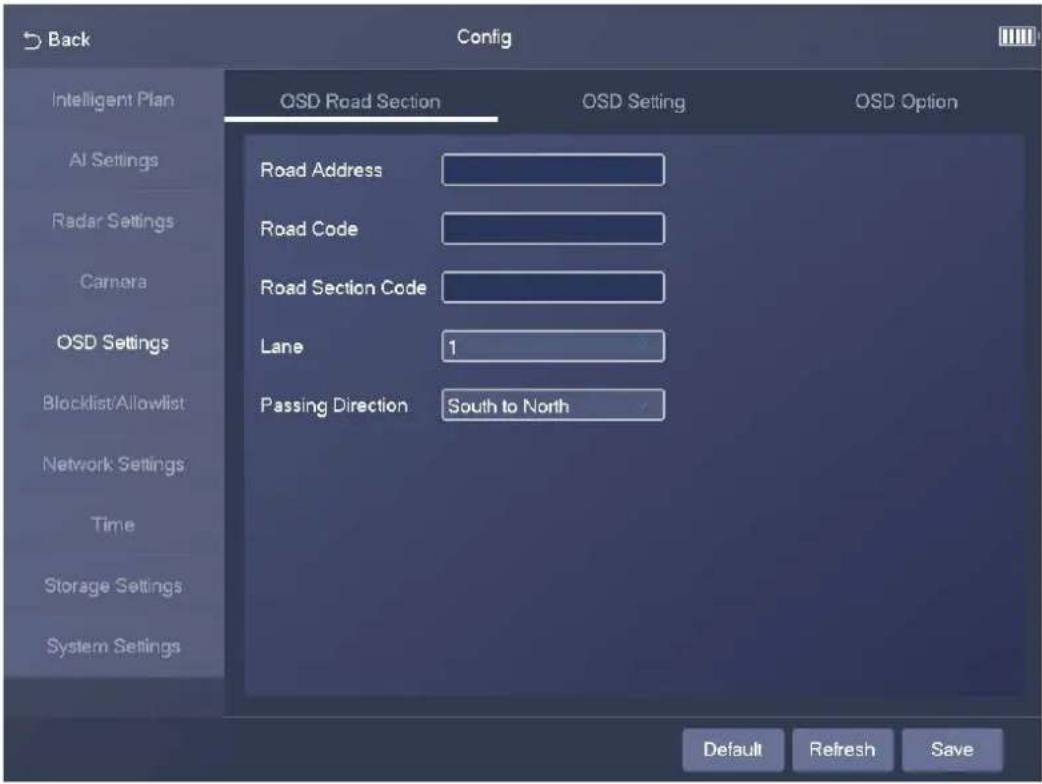
Select Config > OSD Settings > OSD Road Section. On the OSD Road Section tab, you can configure road information, including road address, road code, road section code, lane number, and passing direction.
Figure 3-17 OSD road section
3.4.5.2 OSD Setting
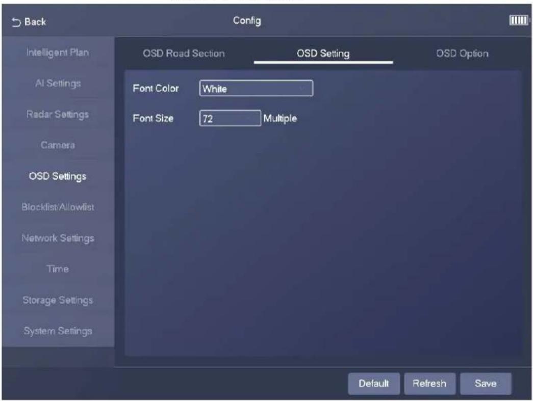
Select Config > OSD Settings > OSD Setting. On the OSD Setting tab, you can configure the font color and font size of OSD information.
Figure 3-18 OSD setting
3.4.5.3 OSD Option
Step 1 Select Config > OSD Settings > OSD Option.
Figure 3-19 OSD information
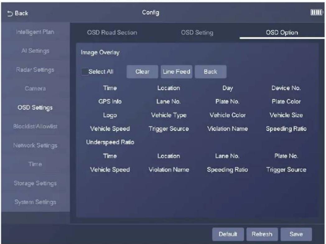
Step 2 Add OSD options.
- Tap an OSD option to add it.
- Select Select All to add all OSD information.
Step 3 Tap Save.
3.4.6 Blocklist/Allowlist
Set the allowlist and blocklist of vehicles.
- Allowlist: When vehicles in the allowlist are detected, the Device discards the captured vehicle violation images without any processing.
- Blocklist: When vehicles in the blocklist are detected, the Device triggers linked actions.
3.4.6.1 Allowlist
Step 1 Select Config > Blocklist/Allowlist > Allowlist.
Step 2 Tap Add, and then configure the parameters.
Figure 3-20 Add
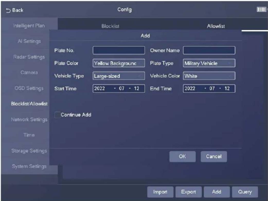
Step 3 Tap OK.

Select Continue Add, and then you can continue to add more plate numbers after you tap OK.
3.4.6.2 Blocklist
Select Config > Blocklist/Allowlist > Blocklist. The setting of a blocklist is similar to that of an allowlist. For details, see "3.4.6.1 Allowlist".
3.4.7 Network Settings
3.4.7.1 Network Settings
Step 1 Select Config > Network Settings > Network Settings.
Figure 3-21 Network settings
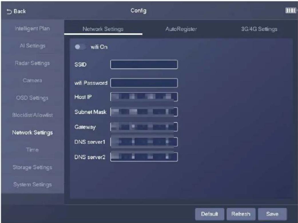
Step 2 Tap to enable Wi-Fi.
• SSID: the name of the Wi-Fi network.
- wifi Password: the password of the Wi-Fi network.
Step 3 Configure the network settings, including host IP address, subnet mask, gateway, and DNS server.
Step 4 Tap Save.
3.4.7.2 Auto Register
Step 1 Select Config > Network Settings > AutoRegister.
Figure 3-22 Auto register
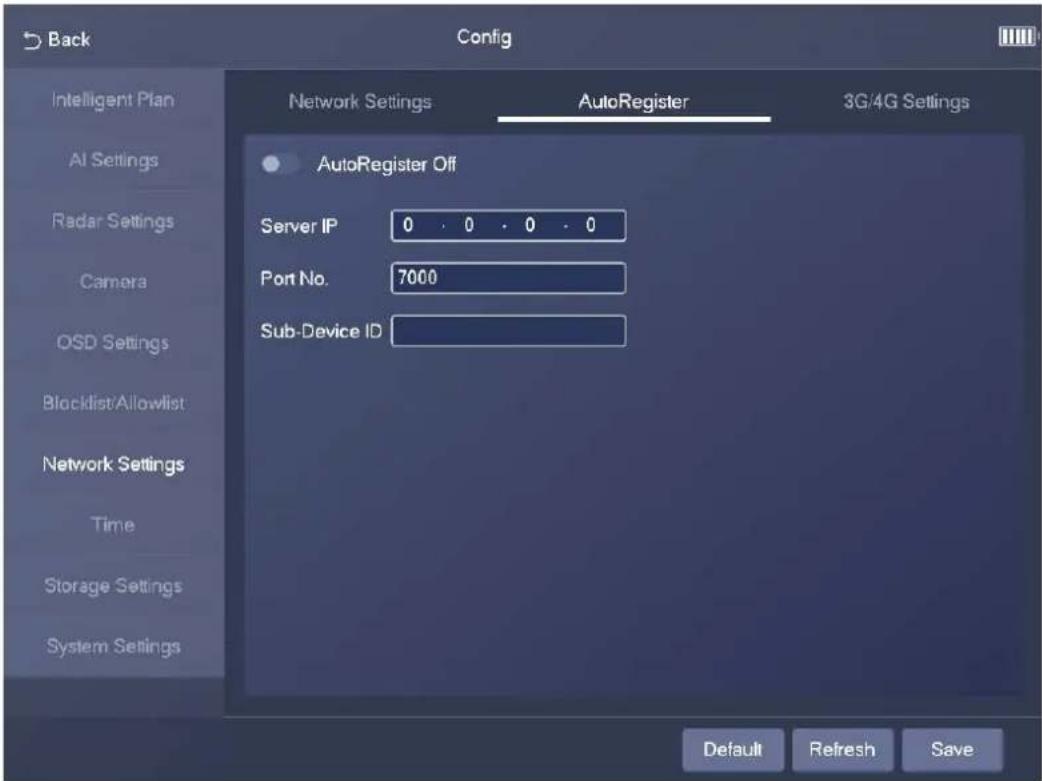
Step 2 Tap to enable the auto register function.
Step 3 Enter the IP address of server that needs to be registered, and also the port for auto registration.
Step 4 Enter the Sub-Device ID, which is the device ID assigned by the server for auto registration. Make sure that there are no repeated device IPs.
Step 5 Tap Save.
3.4.7.3 3G/4G Settings
Step 1 Select Config > Network Settings > 3G/4G Settings.
Figure 3-23 3G/4G settings
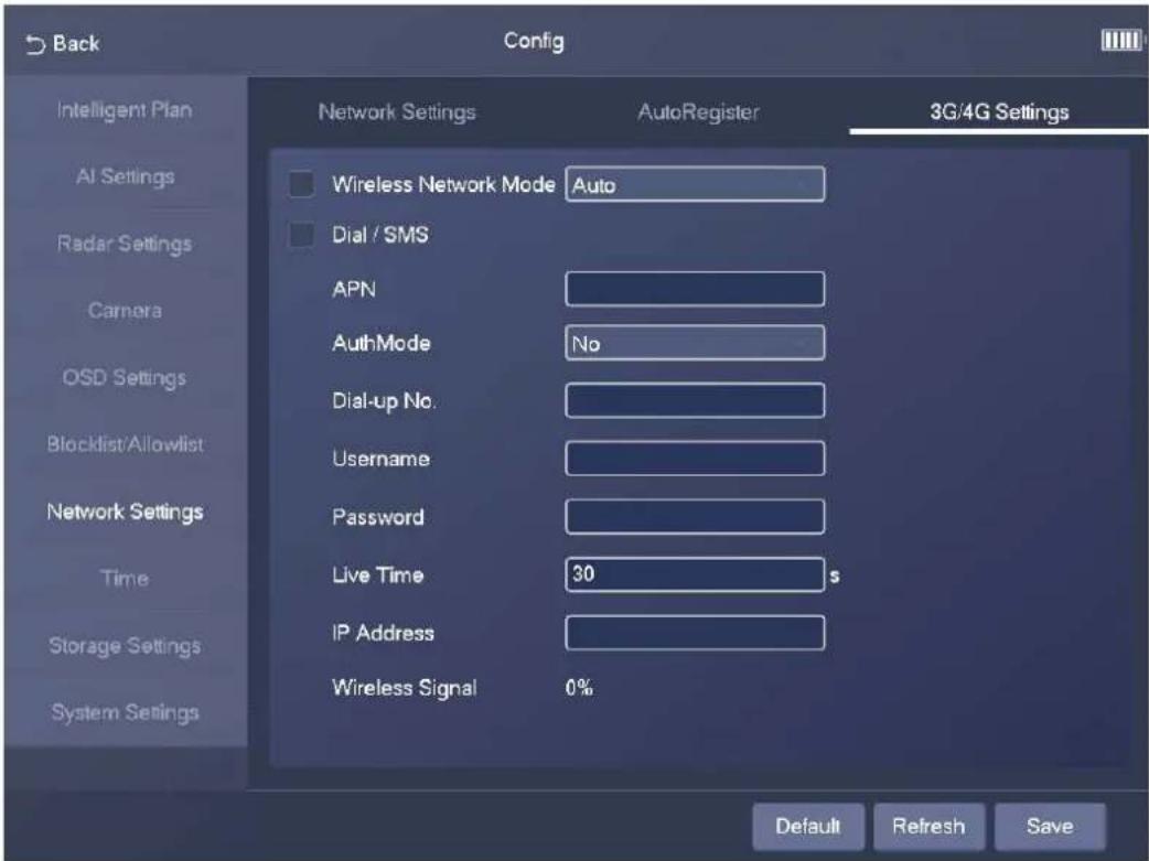
Step 2 Select Wireless Network Mode.

If you set Wireless Network Mode to Auto, the wireless network automatically changes based on the actual situation.
Step 3 Select Dial/SMS, and then configure APN information, such as APN, dial number, username, and password.
Step 4 Tap Save.
3.4.8 Time
3.4.8.1 NTP Setting
Step 1 Select Config > Time > NTP Setting.
Step 2 Tap, and then configure the parameters.
Figure 3-24 NTP setting
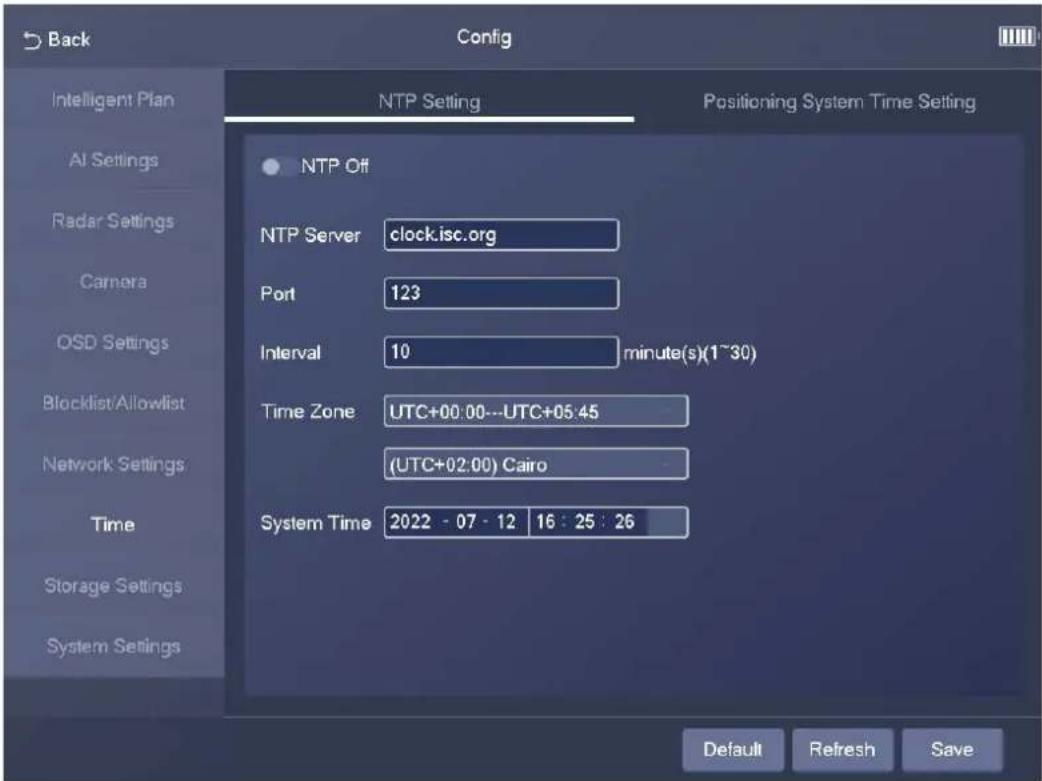
Table 3-6 Description of NTP parameters
| Parameter Description | |
| NTP Server | The IP address and the port number of NTP server. |
| Port | |
| Interval | The time synchronization interval of the Device and the NTP or satellite. |
| Time Zone The time zone where the Device is located. | |
| System Time | The current time of the Device. |
Step 3 Tap Save.
3.4.8.2 Positioning System Time Setting
Step 1 Select Config > Time > Positioning System Time Setting.
Step 2 Tap, and then configure the parameters.
Figure 3-25 Positioning system time setting
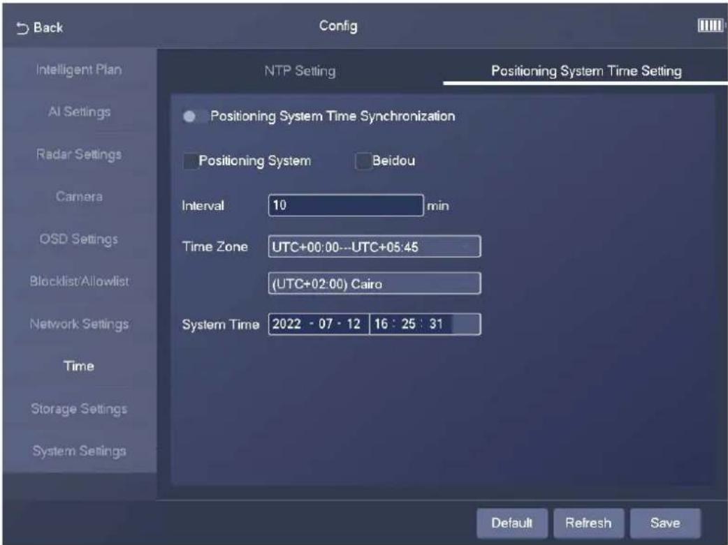
Table 3-7 Description of synchronization parameters
| Parameter Description | |
| Positioning System | Select the checkbox to enable GPS positioning. |
| Beidou | Select the checkbox to enable Beidou positioning. |
| Interval | The time synchronization interval of the Device and the NTP or satellite. |
| Time Zone The time zone where the Device is located. | |
| System Time | The current time of the Device. |
3.4.9 Storage Settings
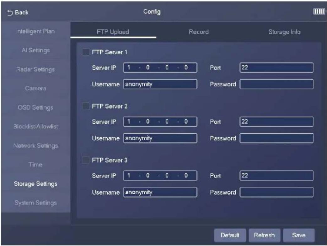
3.4.9.1 FTP Upload
Select Config > Storage Settings > FTP Upload. On the FTP Upload tab, you can configure multiple FTP servers.
Figure 3-26 FTP server
3.4.9.2 Record
Step 1 Select Config > Storage Settings > Record.
Figure 3-27 Record
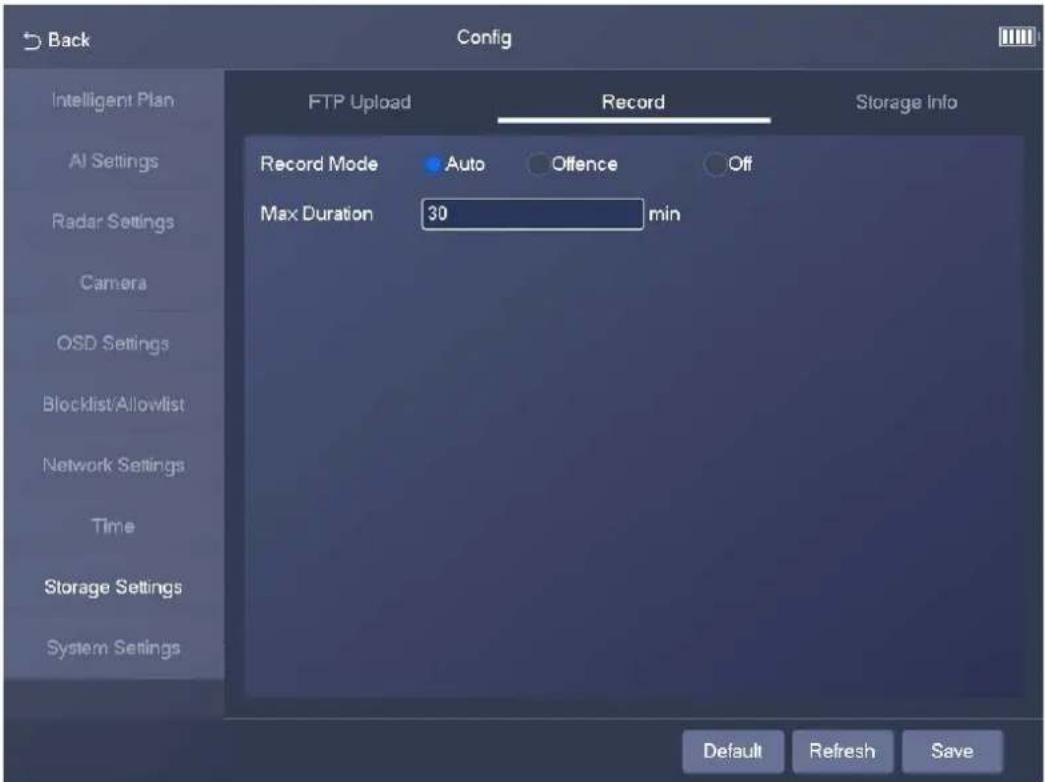
Step 2 Select the record mode.
• Auto: Record videos continuously
- Offence: Record videos only when a traffic violation event is detected.
• Off: Do not record videos.
Step 3 Set the maximum duration of recorded videos.
Step 4 Tap Save.
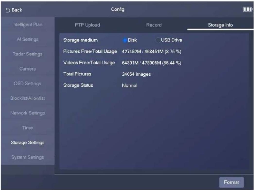
Select Config > Storage Settings > Storage Info. On the Storage Info tab, you can view storage information, including storage medium, storage space, storage status, and the total number of images.
Figure 3-28 Storage info
3.4.10 System Settings
3.4.10.1 General Settings
Step 1 Select Config > System Settings > General Settings.
Figure 3-29 General settings
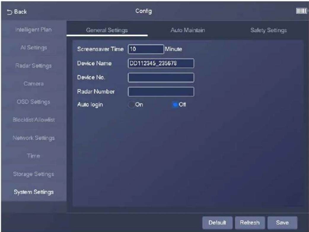
Step 2 Configure the parameters.

Select On to enable auto login.
Step 3 Tap Save.
3.4.10.2 Auto Maintain
Step 1 Select Config > System Settings > Auto Maintain.
Figure 3-30 Auto maintain
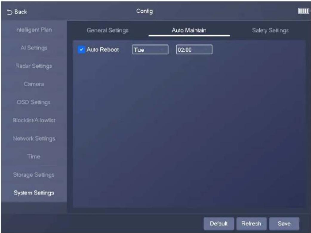
Step 2 Select Auto Reboot, and then configure the day and time. The system will automatically restart at the defined day and time.
Step 3 Tap Save.
3.4.10.3 Safety Settings
You can enable multiple system services to secure network safety.
Step 1 Select Config > System Settings > Safety Settings.
Step 2 Enable the services.
Figure 3-31 System service
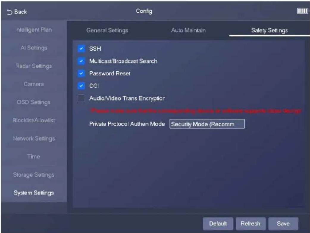
Table 3-8 Description of system service parameters
| Parameter Description | |
| SSH | Secure Shell (SSH) is a cryptographic network protocol for operating network services securely over an unsecure network. It is a method for secure remote login, providing secure access for users. |
| Multicast/Broadcast Search | Multicast identifies logical groups of computers group members. This allows a single message to be sent to the group. Broadcast allows all devices on the same network segment to see the same message. |
| Password Reset | Enable it so that you can reset the password. |
| CGI | Select the Enable checkbox to enable Common Gateway Interface (CGI) service. |
| Audio/Video Trans Encryption | Enable this function to encrypt stream transmitted through private protocol. Make sure that the matched device or software supports the video decryption function.We recommend enabling the encryption service to avoid data leak. Make sure that the matched device or software supports the video decryption function.We recommend enabling the encryption service to avoid data leak. |
| Private Protocol Authen Mode | Security Mode is recommended. |
Step 3 Tap Save.
3.5 Manage Info
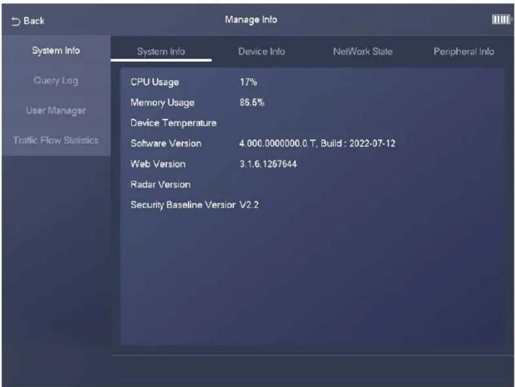
3.5.1 System Info
Tap Manage Info, and then the System Info page appears. On the System Info page, you can view system information, device information, network status, and peripheral information on different tabs.
Figure 3-32 System information
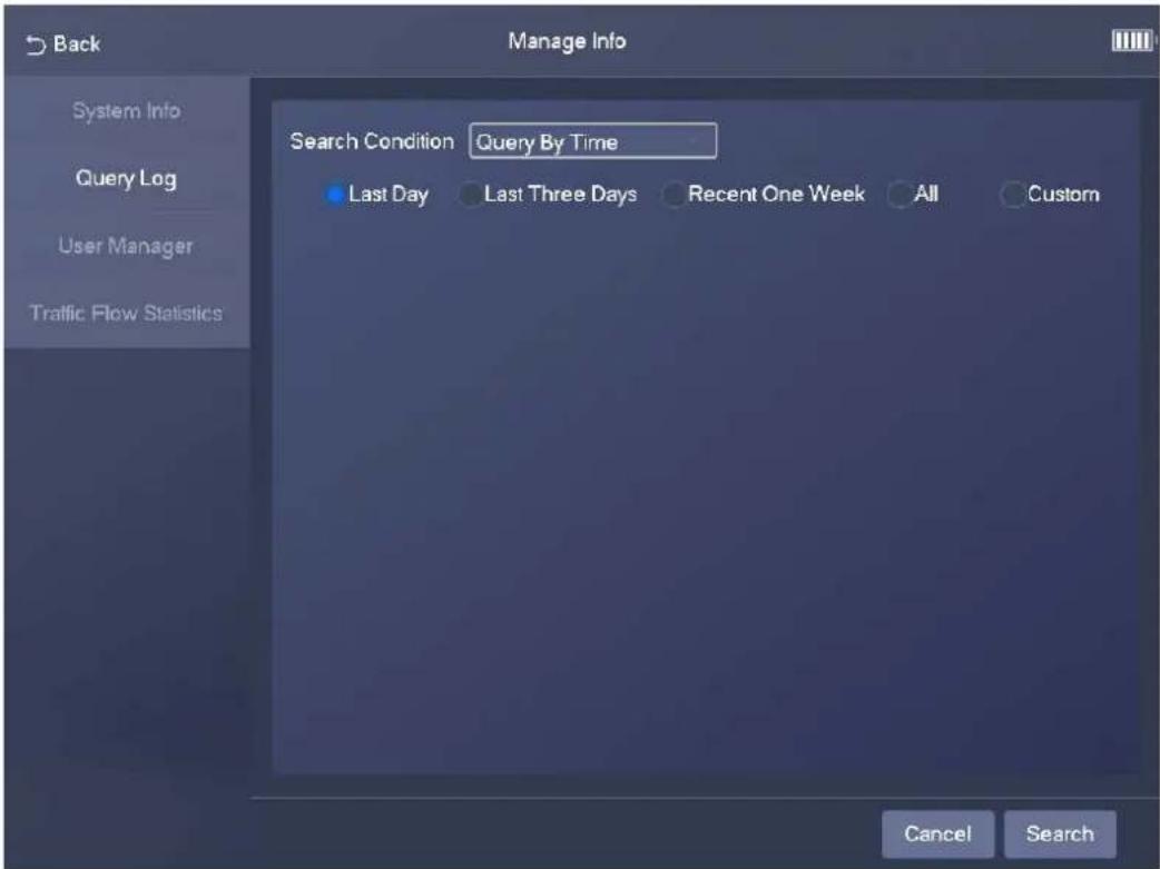
3.5.2 Log Search
Step 1 Select Config > Query Log.
Step 2 Set search conditions, and the tap Search.
The search results are displayed in a list.
Figure 3-33 Log search
3.5.3 User Manager
Step 1 Select Config > User Manager.
Step 2 Tap Add User, and then configure user information, including username, password, group, and permissions.
Figure 3-34 Add a user
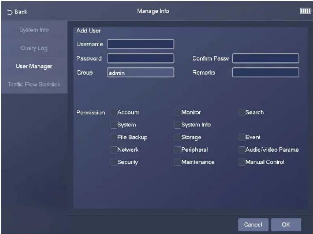
Step 3 Tap OK.
3.5.4 Traffic Flow Statistics
Step 1 Select Manage Info > Traffic Flow Statistics.
Step 2 Tap to enable flow data collection.
Figure 3-35 Traffic flow statistics
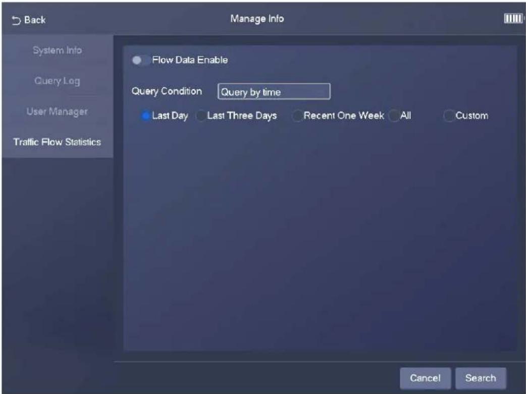
Step 3 Set search conditions, and then tap Search to search for traffic flow data.
4 Webpage Operations
4.1 Introduction
Before you use the webpage of the Device, you must initialize the Device and configure its settings on the webpage. The following sections introduce the initialization and webpage functions of the Device.

The actual webpage might vary depending on the model you purchased and the version of software. The figures in this manual are only for reference.
4.1.1 Initialization
The Device is delivered in the uninitialized state. You must initialize the Device before you can use the webpage of the Device.
Step 1 Use ping X.X.X.X (IP address of the Device) command to check whether the network is connected.
Step 2 Open a browser, enter the IP address of the Device in the address bar, and then press the Enter key.

Make sure that the IP address of the PC and that of the Device are on the same network segment.
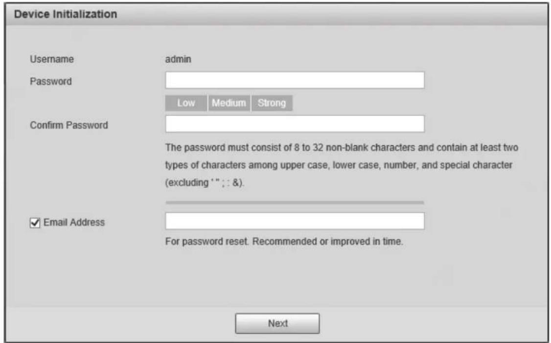
Step 3 In the Device Initialization dialog box, enter your new password.
Step 4 Select Email Address, and then enter your email address. This helps you reset your password when you forgot your password.
Step 5 Click Next.
Figure 4-1 Device initialization
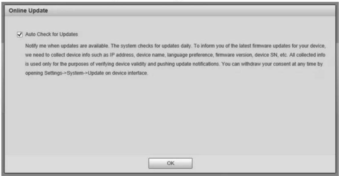
Step 6 In the Online Upgrade dialog box, select Auto-check for updates and click Confirm.
Figure 4-2 Online upgrade
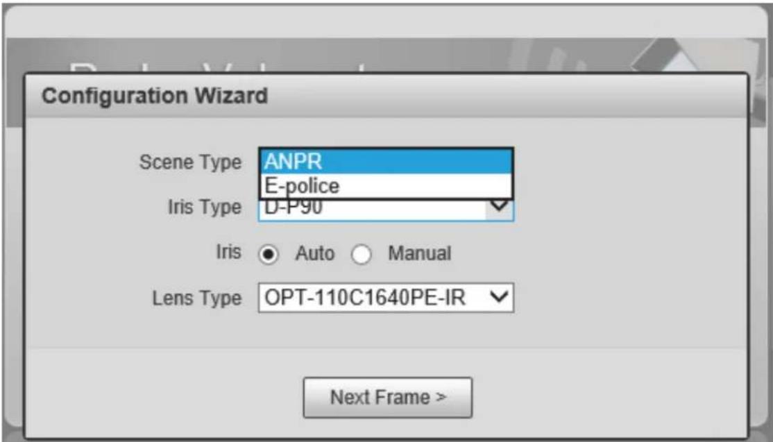
Step 7 In the Configuration Wizard dialog box, set the parameters as needed, and then click Next Frame.
Figure 4-3 Configuration wizard (1)
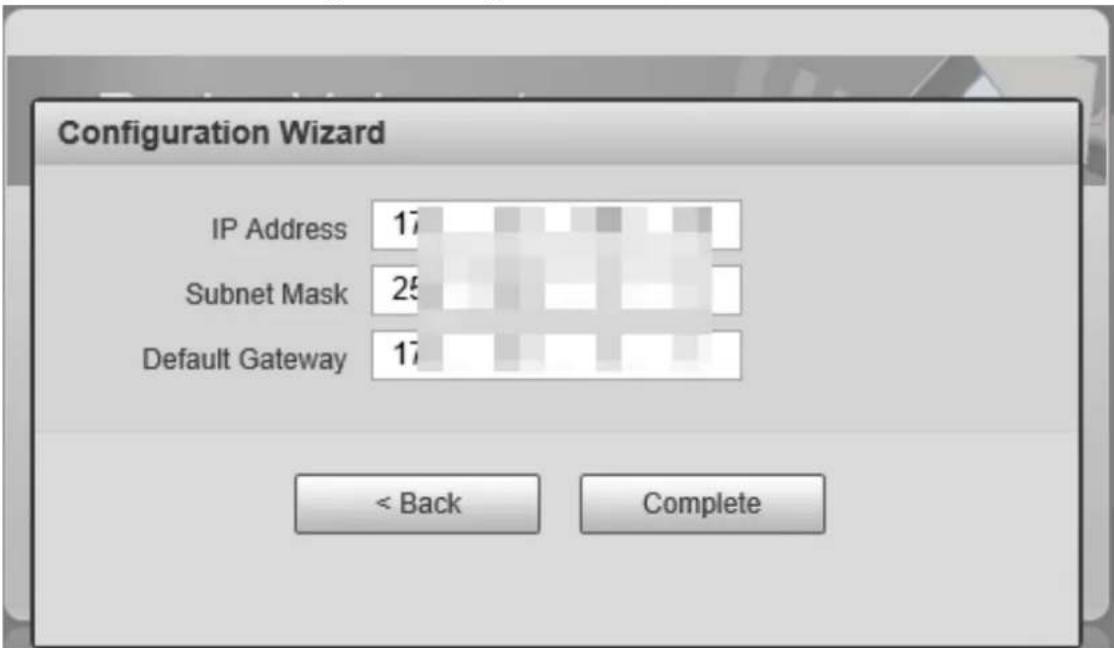
Step 8 Set IP Address, Subnet Mask, and Default Gateway, and then click Complete.
Figure 4-4 Configuration wizard (2)
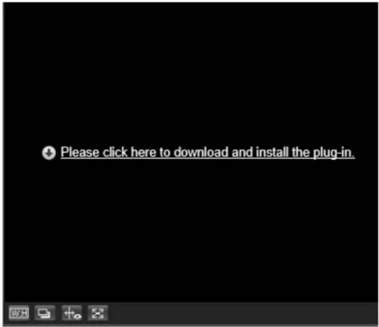
Step 9 For first-time login, click Please click here to download and install the plug-in, and then install the plug-in.
Figure 4-5 Install the plug-in
4.1.2 Webpage Functions
Figure 4-6 Top navigation bar

Table 4-1 Webpage functions
| Function Description | |
| Live | You can view real-time video and image, record videos and capture images, and configure video play and image settings. For details, see "4.2 Live". |
| Radar | You can configure radar settings and debug detection results in a visualized manner. For details, see "4.3 Radar". |
| Search | You can search for vehicles and recorded videos. For details, see "4.4 Search". |
| Setting | You can configure intelligent traffic rules, basic information of the Device, network settings, event management, storage management, and system management. For details, see "4.5 Setting". |
| Alarm | You can configure how the Device responds when alarms occur. For details, see "4.6 Alarm". |
| Logout Log out of the webpage. | |
The following table describes the common buttons on the webpage.
Table 4-2 Common buttons
| Button Description | |
| Default | Restores the parameters to default values. |
| Refresh | Restores the parameters to the values saved last time. |
| Save | Saves the current parameter values. |
4.2 Live
The Live page is displayed after you log in to the webpage. On this page, you can view real-time video and image, captured license plate, and event details. In addition, you can take snapshots and perform other operations.
Figure 4-7 Live page
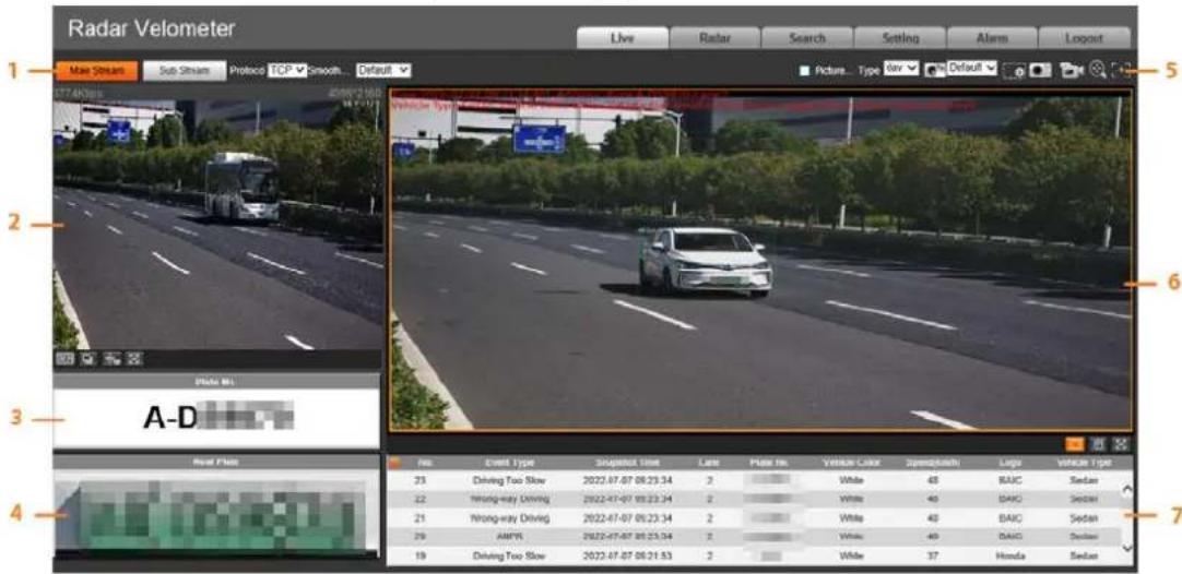
Table 4-3 Description of the Live page
| No. | Description |
| 1 | Video stream |
| 2 | Live view |
| 3 | Plate number recognition |
| 4 | Plate snapshot |
| 5 | Functions on the Live page |
| 6 | Vehicle snapshot |
| 7 | Event list |
4.2.1 Video Stream
- Main Stream: Make sure that the Device can record videos and carry out video surveillance when the network is normal. You can configure main stream resolution within the supported range of the Device.
- Sub Stream: Replaces the main stream to carry out video surveillance and reduces the network bandwidth usage when network bandwidth is insufficient.
- Protocol: The video surveillance protocol. Currently, the system supports only TCP.
- Smoothness Adjustment: The fluency of viewing the real-time video. The fluency can be set to High, Middle, Low, or Default (recommended).
4.2.2 Live View
Displays the real-time video captured by the Device. You can click the icons to change the display mode of live view.
- After you click the icon, Original and Adaptive appear.
◇ Original: Displays the video in its original size.
Adaptive: Displays the video in a self-adaptive window. - After you click the icon, a big window appears. To exit the big window, click the icon again.
- After you click the icon, the image adjustment window appears on the right and the icon becomes 1c close the image adjustment window, click .
- 100% After you click the icon, the video is stretched to fill the window and the icon becomes 100% To switch back to the original size, click 100%
- After you click the icon, smart track detection is enabled. Number plate, vehicle bounding box, and other smart tracking information will be displayed in the video.
- After you click the icon, the video is displayed in full screen. To exit the full screen, double-click the screen.
Figure 4-8 Image adjustment window
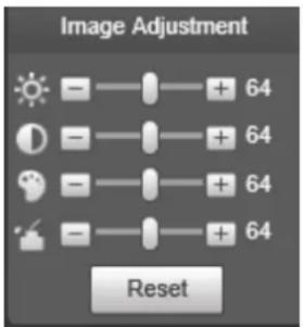
Table 4-4 Image adjustment
| Icon Description | |
 | Adjust the image brightness. Change the value when the image is too bright or too dark. The range is from 0 to 128 (64 by default). |
 | Adjust the image contrast. Change the value when the image brightness is suitable, but contrast is not enough. The range is from 0 to 128 (64 by default). |
 | Adjust the image hue. For example, change red to blue. The default value is made by the light sensor. Generally, you do not need to adjust the value. The range is from 0 to 128 (64 by default). |
 | Adjust the vividness of colors, without influencing the overall brightness of the image. The range is from 0 to 128 (64 by default). |
 | Click the icon to reset brightness, contrast, saturation, and hue to their default values. |

In the image adjustment window, you can only adjust image brightness, contrast, hue, and saturation of local webpage. To adjust system brightness, contrast, hue and saturation, go to
Setting > Camera > Image > General.
4.2.3 Plate Number Recognition
Displays the plate number recognized by the Device in real-time when a vehicle passes.
4.2.4 Plate Snapshot
Displays the snapshot of a license plate when a vehicle passes.
4.2.5 Functions on the Live Page
Table 4-5 Description of functions on the Live page
| Icon Name Description | ||
 | Picture Preview | |
 | Type | Set the format of the recorded videos (dav by default). |
 | Manual Snapshot | After you click the icon, the Device takes a snapshot.To use the function, you must enable Picture Preview first.To configure the storage path of the snapshots, go to Setting > Storage > Storage Path > Path. |
 | Digital Zoom | After you click the icon, select an area in the video window. Then, the selected area is zoomed into. You can right-click the video window or click to disable the function. |
 | Snapshot | After you click the icon, the Device takes a snapshot and the snapshot is displayed on your computer.To configure the storage path of the snapshots, go to Setting > Storage > Storage Path > Path. |
 | Video | |
 | Zoom & Focus | |
 | Aux Focus | |
4.2.6 Vehicle Snapshot
Select Picture Preview, and then snapshots are displayed when vehicles pass.
4.2.7 Event List
Select Picture Preview, and then event information is displayed, including event types, capture time, lanes, plate numbers, vehicle colors, speeds, vehicle signs, and vehicle types.
4.3 Radar
4.3.1 Radar Settings
4.3.1.1 Calibrating the Radar
Make sure that the camera can capture the right targets when the radar sends signals to the camera.
Step 1 Select Radar > Radar Settings.
Step 2 In the Calibration Config section, click Calibrate by Radar and Video.
Step 3 Select Splicing Calibration.
You can also manually calibrate the radar without enabling splicing calibration. In this case, you need to manually measure the distance between the drawn calibration area and the camera.
Figure 4-9 Radar calibration
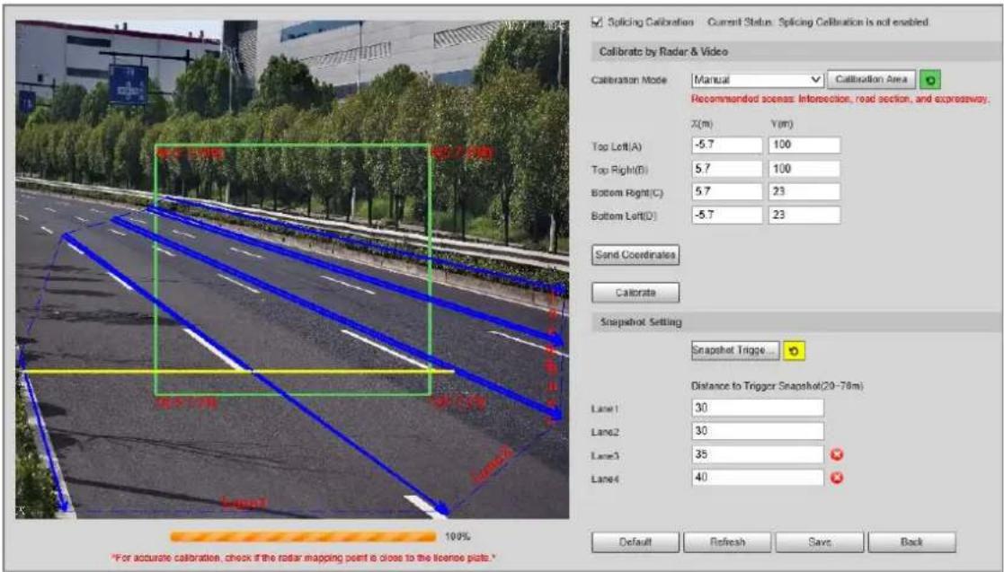
Step 4 Calibrate the radar.
- Manual calibration
Manually set the coordinates of the calibration area and the trigger distance.
- Select Manual from the Calibration Mode drop-down list, and then adjust the calibration area on the image based on the on-site measurement.
You can also click 📞, and then draw a calibration area on the image.
-
Click Send Coordinates to set the coordinates of the calibration area.
-
In the Snapshot Setting section, click Snapshot Triggering Line, and then draw lines on each lane.
The distance between the trigger line and the camera is displayed at the bottom.
- Click Calibrate, and then click Save.
• Automatic calibration
Set the width of the calibration area to the width of the actual road. Then, the algorithm will automatically calibrate the radar.
- Select Manual Assistance from the Calibration Mode drop-down list.
- Set Area Width to the width of the actual road.
- Click Calibrate, and then click Save.
Step 5 Click Back.
4.3.1.2 Configuring General Information
Set the parameters of the radar and the lanes.
Step 1 Select Radar > Radar Settings.
The radar information is displayed on the top of the page, and you can adjust the sensitivity of the radar.

We recommend you leave the sensitivity as default to avoid false detections.
Step 2 In the Road Information Config section, set the lane width and direction based on the
actual situation.
Figure 4-10 Radar and lane information
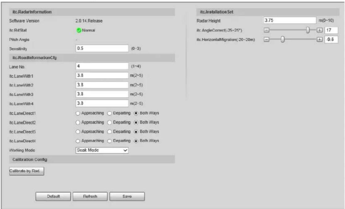
Step 3 In the Installation Settings section, set the installation information of the Device.
Table 4-6 Installation information
| Parameter Description | |
| Radar Height | The installation height of the Device. |
| Angle Correction | The installation angle of the Device. Make sure that the angle is the same as that in Radar Visualization. |
| Horizontal Offset | The horizontal offset of the Device. Make sure that the horizontal offset is the same as that in Radar Visualization. |
4.3.2 Radar Visualization
On the Radar Visualization tab, you can view the effect of radar detection in real time and modify some of the radar parameters.
Step 1 Select Radar > Radar Visualization.
Step 2 Adjust the value of angle correction and horizontal offset.
You can click the image at the lower-right corner to check correction standards.
Step 3 Click Close On to display the trajectory of detected targets.
Figure 4-11 Radar visualization
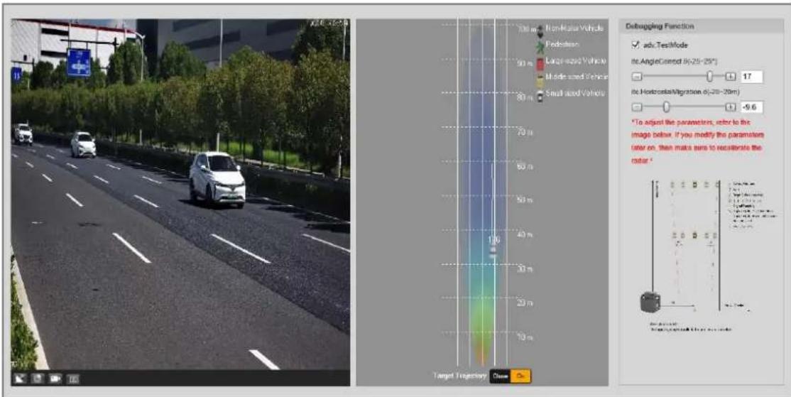
Step 4 Click to view the detection points of the radar on targets.

If a target is large and the detection sensitivity is set high, the radar might recognize it as 2 targets.
4.4 Search
You can set search conditions to search for vehicles or recorded videos, and set file or time as download type to download related data.
4.4.1 Searching for Vehicles
Step 1 Click Search, and then select Vehicles.
Step 2 Set search conditions.
- Set basic parameters such as start time, end time, and image type.
- Click OSD Option, and then select more options as needed.
- Select whether to only search for composed images and vehicles on the blocklist.
Step 3 Click Search.
You can click a record on the list to view the image.
Figure 4-12 Search for vehicles
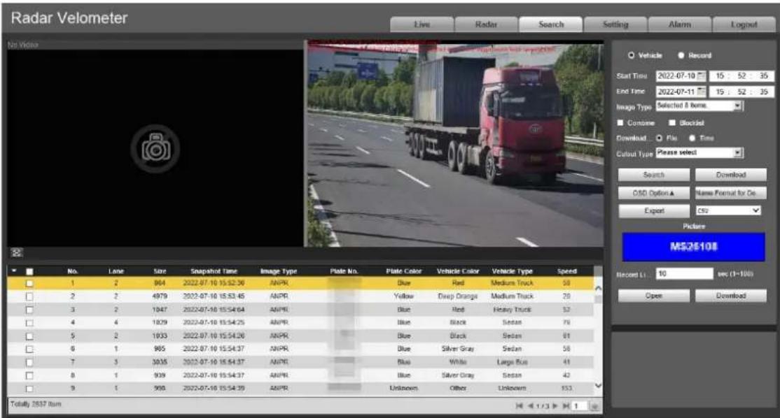
Step 4 Select the download type, and then click Download.
- File: Select one or more images to download from the search results.
• Time: Download all images captured during the defined period. - Cutout Type: Select the cutout type of images to be downloaded. When downloading images, the related cutout image will be separated and downloaded together.
Step 5 Click Name Format for Downloaded Images, click Help next to the corresponding image type, and then customize the naming format in the pop-up window.
Figure 4-13 Naming format
![Naming Format Device No. Local Device IP Passing Direct... Lane No. Speed Speed Limit Violation Type Loop No. Plate No. Vehicle Size Vehicle Color Total Picture... Picture No. Device IP Plate Color Plate Coordin... Violation Code Location Picture Scene Device Name Insert Forward Insert Backward Reset / Separate the folder by i. Year Month Day Hour min sec ms [ Channel No. 1_ Picture No. .jpg 20130106152730110[1]_2.jpg Note 1: % can be displayed by entering %% Note 2: The picture cannot be uploaded if the filename is too long. Note 3: The filename cannot include one of the following characters \ : * ? " < > | Cancel OK](/content/2026/05/1042354/images/e1f0ad4d29d44e47abcda08115d16dd84c0d8931c126df4b0411b6854fde484c.jpg)
Step 6 Click OK.
Step 7 Set the duration of Record Linkage and then download related videos as needed.
4.4.2 Searching for Recorded Videos
Step 1 Click Search, and then select Record.
Step 2 Set the search time, and then click Search.

After the search time is set, set Download Format to Time, and then click Download to download all videos recorded within this period.
Figure 4-14 Search results
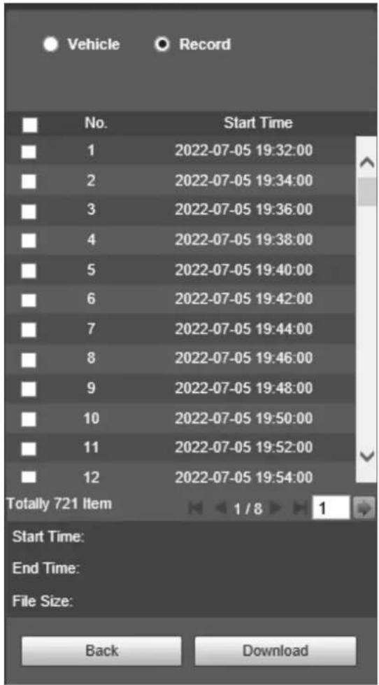
Step 3 Double-click a result to view the video.
Step 4 Select a video, and then click Download to download the selected video to your computer.
4.5 Setting
On the Setting page, you can set the parameters of the Device, including intelligent traffic rules, network settings, remote devices, event management, storage management, system management, and system information.
4.5.1 ITC
You can configure intelligent traffic parameters to provide functions such as image composition and OSD configuration.
4.5.1.1 Smart Plan
Step 1 Select Setting > ITC > Smart Plan.
Step 2 Click E-police or ANPR.

- For details on configuration in ANPR, see "4.5.1.2 ANPR Snapshot".
- For details on configuration in E-police, see "4.5.1.3 E Police".
Figure 4-15 Select a smart plan
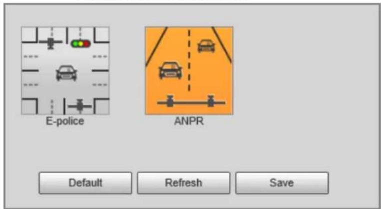
Step 3 Click Save.
When you switch between the smart plans, the system instructs you to restart the Device.
Figure 4-16 Notification
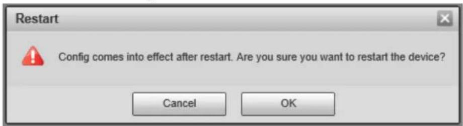
Step 4 Click OK, and then log in to the webpage after the Device is restarted.
4.5.1.2 ANPR Snapshot
4.5.1.2.1 Configuring Violation Snapshot
Configure the video detection parameters for detecting traffic violations.

Select a lane from the list in the Lane Config section, and then all configurations on the Violation Snapshot tab are for this lane.
Lane Parameters
Configure the information of the lanes the Device is monitoring, such as drawing lane lines on the image, selecting the lane direction, and setting the lane line type according to the actual situation.
Step 1 Select Setting > ITC > ANPR Snapshot > Violation Snapshot.
Step 2 In the Lane Config section, configure the lane lines.
- If the default lane lines on the image do not meet the detection requirements, you can draw new lane lines.
- Select a lane from the list, and then delete the lane lines by clicking


You can also click the icon next to Lane Line or Detection Line to delete the corresponding lines on the image.
- Click Lane Line or Detection Line, and then draw lines on the image.
When a vehicle reaches a detection line, the Device takes a snapshot of the vehicle.
- You can also adjust lane lines to match the actual lane lines.
-
Select Edit Line, and then select a lane from the list.
-
Drag to adjust the lane lines and detection lines according to the actual situation.
Figure 4-17 Lane configuration
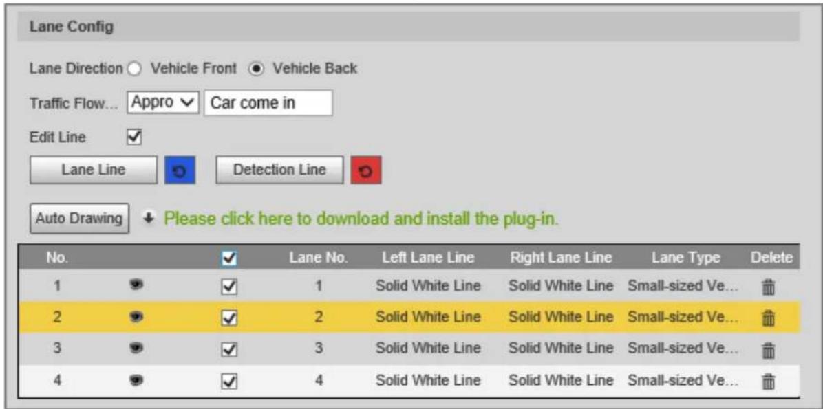
Step 3 Set Lane Direction and Traffic Flow Direction for the selected lane.
- Lane Direction: The direction of the lane line on the image must be the same as the travelling direction of vehicles.
- Traffic Flow Direction: The direction of traffic flow, which is used for traffic flow analysis.
Step 4 Click Auto Drawing, and then the system automatically draws lane lines. You can adjust the auto lines as needed.

Install the plug-in before using the Auto Drawing function.
Step 5 Double-click the selected lane on the list under Left Lane Line, Right Lane Line, or Lane Type to change the lane lines and lane type as needed.
- Click to display or hide the corresponding lane lines on the image.
- Click □ to select a lane for the Device to monitor.
Step 6 Click Save.
Lane Properties
Step 1 Select Setting > ITC > ANPR Snapshot > Violation Snapshot.
Step 2 Select a lane from the list in the Lane Config section.
Step 3 In the Lane Property section, configure lane properties.
Figure 4-18 Lane property
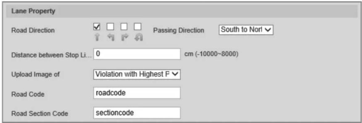
Table 4-7 Lane property description
| Parameter Description | |
| Road Direction | The direction of the road. |
| Passing Direction The geographical direction | of the lane. |
| Distance between Stop Line and Image Bottom | The distance between the stop line and the bottom of the image. |
| Upload Image of | All Violations: Captures and reports all violations of vehicles on the lane.Violation with Highest Priority: If a vehicle triggers multiple violations, the Device reports only the event with the highest priority. |
| Road Code The code of the road. | |
| Road Section Code | The code of the road section. |
Step 4 Click Save.
Rule Configuration
You can select traffic violation types and configure the parameters of captured vehicle images.
Step 1 Select Setting > ITC > ANPR Snapshot > Violation Snapshot.
Step 2 In the Rule Config section, click, and then configure image parameters.
Figure 4-19 Rule configuration
| Rule Config | |||||
| No. | ☐ | Event Type | Snapshot Quantity | Picture Parameter | Advanced |
| 1 | ✓ | ANPR | 1 | ✓ | |
| 2 | ✓ | Wrong-way Driving | 2 | ✓ | |
| 3 | ☐ | Driving Too Slow | 2 | ✓ | |
| 4 | ☐ | Speeding | 2 | ✓ | |
| 5 | ☐ | Illegal Lane Change | 3 | ✓ | |
Figure 4-20 Image parameters
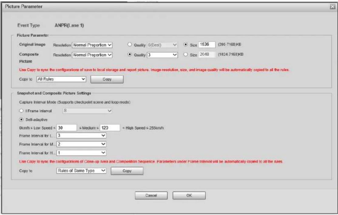
Table 4-8 Description of image parameters
| Section Parameter Description | ||
| Picture Parameter | Original Image | The original image of the vehicle that violates traffic rules. |
| Composite Picture | The composite image consisting of multiple images of the vehicle that violates traffic rules. | |
| Resolution | The resolution of the image. | |
| Quality | The level of the image quality. | |
| Size The maximum size of the image. | ||
| Copy to | Copy the current configuration to rules of the same type or all rules. After selecting an option from Copy to, click Copy. | |
| Snapshot and Composite Picture Settings | I Frame Interval | Set the interval of capturing 2 images to a fixed number of frames. |
| Self-adaptive | Set the interval of capturing 2 images to different number of frames based on the vehicle speed. | |
| Copy to | Copy the current configuration to rules of the same type or all rules. After selecting an option from Copy to, click Copy. | |
Step 3 Click OK.
Step 4 Click ⚙, and then configure advanced parameters.
Figure 4-21 Advanced parameters
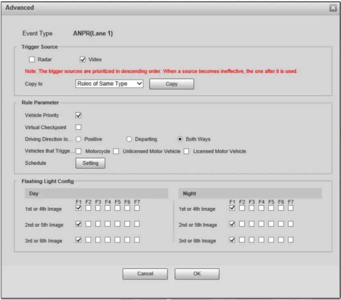
Table 4-9 Description of advanced parameters
| Section Parameter Description | ||
| Trigger Source | Radar | The method that triggers traffic violations. |
| Video | ||
| Copy to | Copy the current configuration to rules of the same type or all rules. After selecting an option from Copy to, click Copy. | |
| Rule Parameter | Driving Direction to Trigger Snapshot | The driving direction of the vehicles that the Device captures. |
| Vehicles that Trigger Snapshots | The types of the vehicles that the Device captures. You can select from Mortorcycle, Unlicensed Motor Vehicle, and Licensed Motor Vehicle. | |
| Schedule | The period during which alarms can be triggered. To set a period, click Setting, and then drag the cursor over the time table or select days and enter hours in the entry fields. | |
| Flashing Light Config | Day | Select which flashing light flashes when snapshots are taken during daytime or night.A snapshot can be associated with up to 5 flashing lights.For example, if you select F1 from 1st or 4th Image, the flashing light F1 flashes when taking the 1st and 4th snapshots. |
| Night | ||
Step 5 Click OK.
Vehicle Detection
Step 1 Select Setting > ITC > ANPR Snapshot > Violation Snapshot.
Step 2 In the Vehicle Detection section, click a line or region type, and then draw a line or region on the image.
- To draw a line, click a line type and then drag the cursor on the image.
- To draw a region, click a region type, and then draw lines by dragging the cursor on the image and make them form a closed region.

To clear the lines that you have drawn, click .
Figure 4-22 Vehicle detection
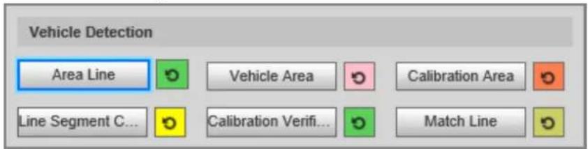
Table 4-10 Description of vehicle detection parameters
| Parameter Description | |
| Area Line | The region of detection. |
| Vehicle Area | The region for detecting traffic flow. |
| Calibration Area | The region for analyzing traffic flow. |
| Line Segment Calibration | Used to verify the accuracy of calibration results.ClickLine Segment Calibrationto draw the calibration segment in the calibration area, enter the actual length of the calibration segment inLength, and then click Calibration Verification. |
| Calibration Verification | Used to verify the accuracy of calibration results. |
Step 3 Click Save.
Other Configuration
Step 1 Select Setting > ITC > ANPR Snapshot > Violation Snapshot.
Step 2 In the Other Config section, configure the parameters.
Figure 4-23 Other configuration
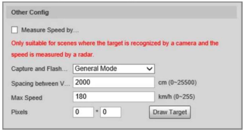
Table 4-11 Other configuration
| Parameter Description | |
| Measure Speed by Radar | Specifies whether to measure vehicle speed by using the radar. |
| Capture and Flash Linkage | General Mode: Recommended for ANPR mode.Snapshot Line Mode: Recommended for E-police mode. |
| Spacing between Vehicles | The distance between vehicles when waiting in a line. |
| Max Speed | If the speed of a vehicle exceeds this value, the system automatically changes the vehicle speed to a random value in the normal range. |
| Pixels | Click Draw Target, and then draw a rectangular area on the image to show the pixel size of the area. |
Step 3 Click Save.
4.5.1.2.2 Configuring Intelligent Analysis
Recognition
Step 1 Select Setting > ITC > ANPR Snapshot > Intelligent Analysis > Recognition.
Step 2 Configure the parameters.
Figure 4-24 Recognition
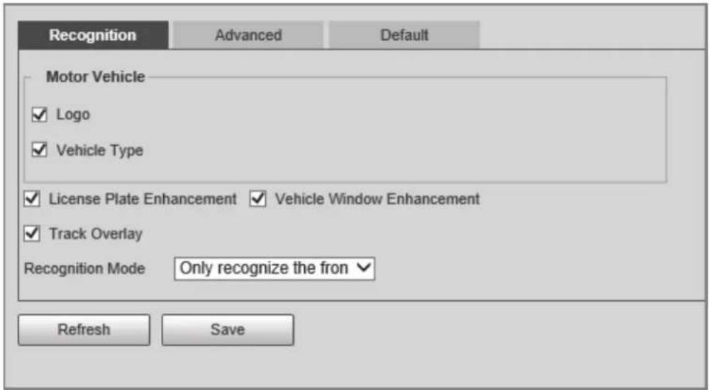
Table 4-12 Description of recognition parameters
| Parameter Description | |
| Motor Vehicle | Supports recognizing vehicle logs and vehicle types. |
| License Plate Enhancement | Select the checkbox to enhance the effect of license plate images. |
| Vehicle Window Enhancement | Select the checkbox to enhance the effect of vehicle window images. |
| Track Overlay | Select the checkbox to enable Track Overlay. After you enable the function and click + on the Live page, you can see that each vehicle is surrounded by a green box. |
| Recognition Mode | Only recognize the front plate: Recognizes and captures the license plate on the vehicle head.Only recognize the rear plate: Recognizes and captures the license plate on the vehicle rear.Front plate priority: Head plate has the priority.Rear plate priority: Rear plate has the priority. |
Step 3 Click Save.
Advanced
Step 1 Select Setting > ITC > ANPR Snapshot > Intelligent Analysis > Advanced.
Figure 4-25 Custom algorithm
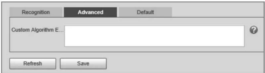
Step 2 Configure a custom algorithm.
Step 3 Click Save.
Default
Step 1 Select Setting > ITC > ANPR Snapshot > Intelligent Analysis > Default.
Step 2 Click Default to restore settings including lane property, violation capture, and intelligent business to default.
4.5.1.2.3 Configuring Original Picture OSD
Configure OSD content, style, and position for captured images.
Step 1 Select Setting > ITC > ANPR Snapshot > Original Picture OSD.
Step 2 Configure OSD black edge position, black edge height, OSD separator, and font size.
Figure 4-26 Original picture OSD
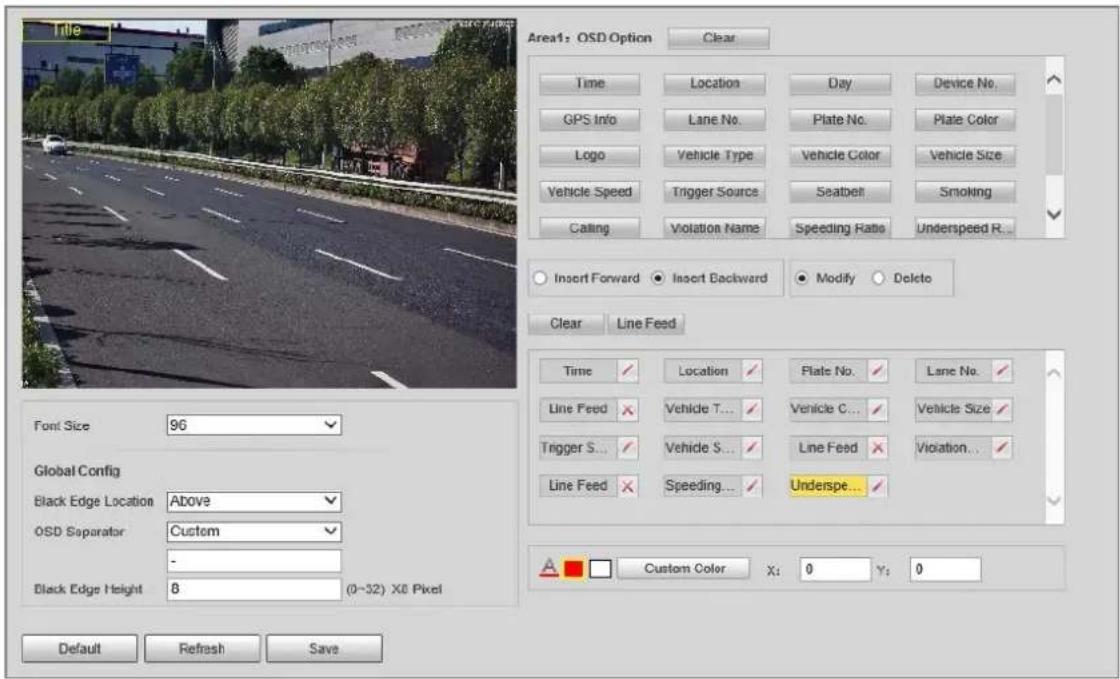
Step 3 Configure the OSD parameters.
Table 4-13 Description of OSD parameters
| Parameter Description | |
| Insert Forward | Select an OSD option, select Insert Forward and then select another OSD option. The new OSD option will be inserted before the previous one. |
| Insert Backward | Select an OSD option, select Insert Backward, and then select another OSD option. The new OSD option will be inserted after the previous one. |
| Modify | Select Modify, and then √ is displayed next to all the selected OSD options. To edit an OSD option, click √ next to the OSD option. |
| Delete | Select Delete, and then ✗ is displayed next to all the selected OSD options. To delete an OSD option, click ✗ next to the OSD option. |
| Clear | Delete all the selected OSD options. |
| Line Feed | To start a new line after an OSD option, select the OSD option, and then click Line Feed. |
Step 4 Click Save.
4.5.1.2.4 Configuring Combination Picture OSD
Step 1 Select Setting > ITC > ANPR Snapshot > Combination Picture OSD.
Step 2 Configure OSD black edge position, black edge height, OSD separator, and font size.
Step 3 Configure the OSD parameters. For details, see Table 4-13.
Step 4 Click Save.
4.5.1.2.5 Configuring Cutout
Step 1 Select Setting > ITC > ANPR Snapshot > Cutout Config.
Step 2 Select the cutout type.
Figure 4-27 Cutout config
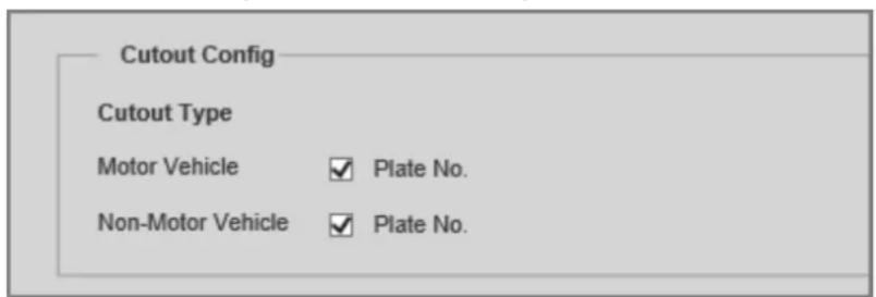
Step 3 In the Target Box section, specify whether to enable the track box for motor vehicles and non-motor vehicles.
Step 4 Click Save.
4.5.1.3 E Police
4.5.1.3.1 Configuring Violation Snapshot
Configure the video detection parameters for detecting traffic violations.

Select a lane from the list in the Lane Config section, and then all configurations on the Violation
Snapshot tab are for this lane.
Lane Parameters
Configure the information of the lanes the Device is monitoring, such as drawing lane lines on the image, selecting the lane direction, and setting the lane line type according to the actual situation.
Step 1 Select Setting > ITC > E Police > Violation Snapshot
Step 2 In the Lane Config section, configure the lane lines.
Figure 4-28 Lane configuration
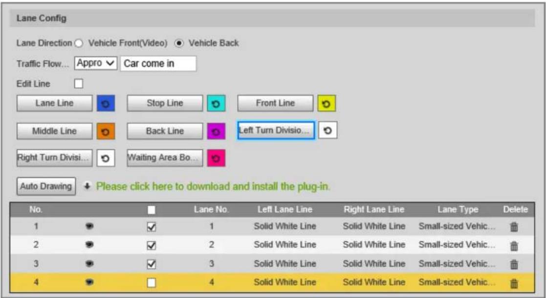
Table 4-14 Lane parameters
| Parameter Description | |
| Lane Direction | The direction of the lane line must be the same as the travelling direction of vehicles.· Vehicle Back: The lane line is upward.· Vehicle Front(Video): The lane line is downward. |
| Traffic Flow Direction | The direction of traffic flow, which is used for traffic flow analysis. |
| Edit Line | After you select the checkbox, you can adjust the lane lines by dragging the angles on the image. |
Step 3 Click a line type, and then draw the lane lines on the image.

To clear the lane lines or regions that you have drawn, click
Table 4-15 Lane lines
| Line type Description | |
| Lane Line | Each lane must have 2 lane lines, shown as blue lines with arrows. The arrow indicates the direction in which the vehicles travel.The drawn lines should go along the actual lane line. |
| Stop Line The actual stop line on the road. | |
| Front Line | The line that triggers the first capture of the vehicle running the red light or traveling on the wrong lane. |
| Middle Line | The line that triggers the second capture of the vehicle running the red light or traveling on the wrong lane. |
| Back Line | Used to judge whether a vehicle is going straight. It triggers the third capture of the vehicle running the red light (straight going) or traveling on the wrong lane. |
| Line type Description | |
| Left Turn Division | Used to judge whether a vehicle is turning left. It triggers the third capture of the vehicle running the red light or traveling on the wrong lane. |
| Right Turn Division | Used to judge whether a vehicle is turning right. It triggers the third capture of the vehicle running the red light or traveling on the wrong lane. |
| Waiting Area Boundaries | The end line of the waiting area. Going beyond it will be regarded as running the red light. |
Step 4 Click Auto Drawing, and then the system automatically draws lane lines. You can adjust the auto lines as needed.

Install the plug-in before using the Auto Drawing function.
Step 5 Double-click the selected lane on the list under Left Lane Line, Right Lane Line, or Lane Type to change the lane lines and lane type as needed.
- Click to display or hide the corresponding lane lines on the image.
- Click □ to select a lane for the Device to monitor.
Step 6 Click Save.
Lane Properties
Step 1 Select Setting > ITC > E Police > Violation Snapshot.
Step 2 Select a lane from the list in the Lane Config section.
Step 3 In the Lane Property section, configure lane properties.
Figure 4-29 Lane property
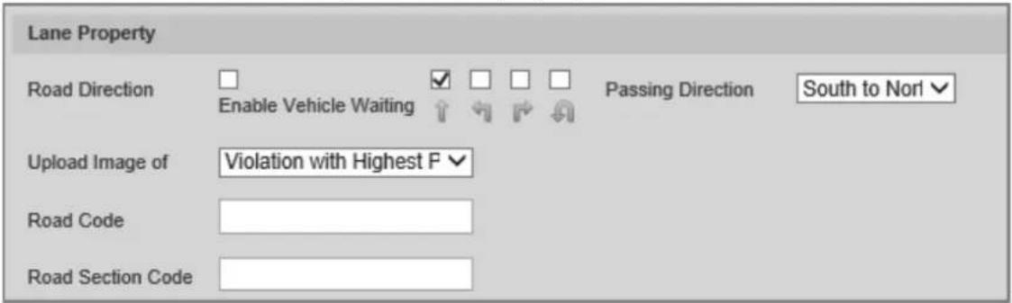
Table 4-16 Lane property description
| Parameter Description | |
| Road Direction | The direction of the road. |
| Passing Direction The geographical direction of the lane. | |
| Upload Image of | All Violations: Captures and reports all violations of vehicles on the lane.Violation with Highest Priority. If a vehicle triggers multiple violations, the Device reports only the event with the highest priority. |
| Road Code The code of the road. | |
| Road Section Code | The code of the road section. |
Step 4 Click Save.
Rule Configuration
You can select traffic violation types and configure the parameters of captured vehicle images.
Step 1 Select Setting > ITC > E Police > Violation Snapshot
Step 2 In the Rule Config section, click, and then configure image parameters.
Figure 4-30 Rule configuration
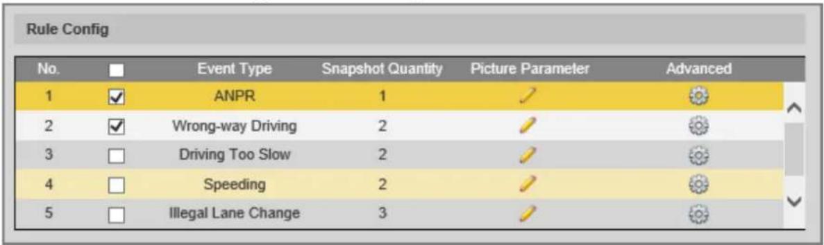
Figure 4-31 Image parameters
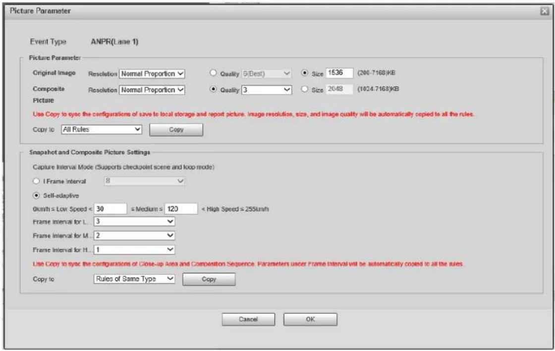
Table 4-17 Description of image parameters
| Section Parameter Description | ||
| Picture Parameter | Original Image | The original image of the vehicle that violates traffic rules. |
| Composite Picture | The composite image consisting of multiple images of the vehicle that violates traffic rules. | |
| Resolution | The resolution of the image. | |
| Quality | The level of the image quality. | |
| Size The maximum size of the image. | ||
| Copy to | Copy the current configuration to rules of the same type or all rules. After selecting an option from Copy to, click Copy. | |
| Snapshot and Composite Picture Settings | I Frame Interval | Set the interval of capturing 2 images to a fixed number of frames. |
| Self-adaptive | Set the interval of capturing 2 images to different number of frames based on the vehicle speed. | |
| Copy to | Copy the current configuration to rules of the same type or all rules. After selecting an option from Copy to, click Copy. | |
Step 3 Click OK.
Step 4 Click ⚙, and then configure advanced parameters.
Figure 4-32 Advanced parameters
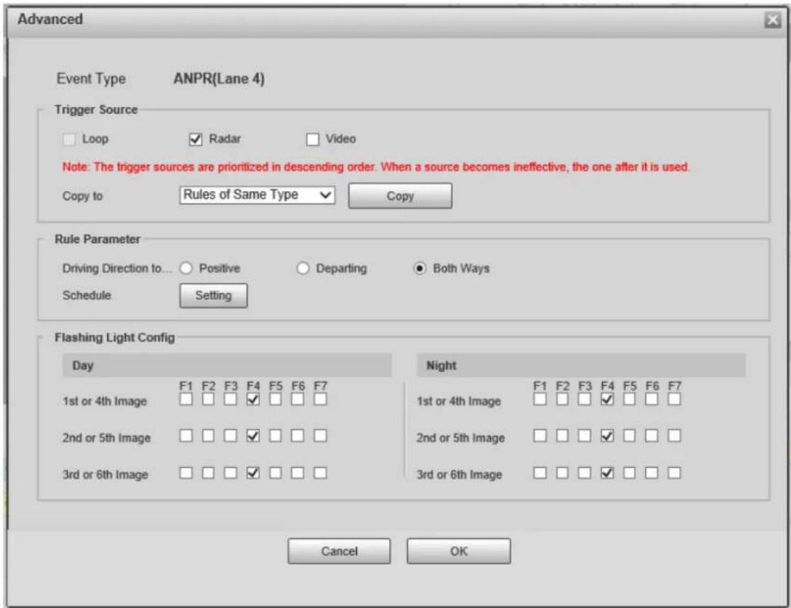
Table 4-18 Description of advanced parameters
| Section Parameter Description | ||
| Trigger Source | Loop Unavailable | |
| Radar | The method that triggers traffic violations. | |
| Video | ||
| Copy to | Copy the current configuration to rules of the same type or all rules. After selecting an option from Copy to, click Copy. | |
| Rule Parameter | Driving Direction to Trigger Snapshot | The driving direction of the vehicles that the Device captures. |
| Schedule | The period during which alarms can be triggered. To set a period, click Setting, and then drag the cursor over the time table or select days and enter hours in the entry fields. | |
| Flashing Light Config | Day | Select which flashing light flashes when snapshots are taken during daytime or night.A snapshot can be associated with up to 5 flashing lights.For example, if you select F1 from 1st or 4th Image, the flashing light F1 flashes when taking the 1st and 4th snapshots. |
| Night |
Step 5 Click OK.
Vehicle Detection
Step 1 Select Setting > ITC > E Police > Violation Snapshot
Step 2 In the Vehicle Detection section, click a line or region type, and then draw a line or region on the image.
- To draw a line, click a line type and then drag the cursor on the image.
- To draw a region, click a region type, and then draw lines by dragging the cursor on the image and make them form a closed region.

To clear the lines that you have drawn, click .
Figure 4-33 Vehicle detection
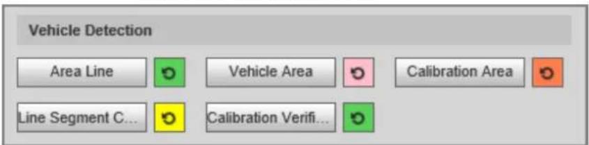
Table 4-19 Description of vehicle detection parameters
| Parameter Description | |
| Area Line | The region of detection. |
| Vehicle Area | The region for detecting traffic flow. |
| Calibration Area | The region for analyzing traffic flow. |
| Line Segment Calibration | Used to verify the accuracy of calibration results.Click Line Segment Calibration to draw the calibration segment in the calibration area, enter the actual length of the calibration segment in Length, and then click Calibration Verification. |
| Calibration Verification | Used to verify the accuracy of calibration results. |
Step 3 Click Save.
Other Configuration
Step 1 Select Setting > ITC > E Police > Violation Snapshot
Step 2 In the Other Config section, configure the parameters.
Figure 4-34 Other configuration
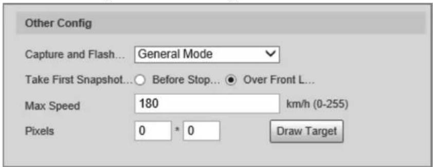
Table 4-20 Other configuration
| Parameter Description | |
| Capture and Flash Linkage | General Mode: Recommended for ANPR mode.Snapshot Line Mode: Recommended for E-police mode. |
| Take First Snapshot for Running a Red Light | Before Stop Line: The first snapshot of running a red light is taken before the stop line.Over Front Line: The first snapshot of running a red light is taken over the front line. |
| Max Speed | If the speed of a vehicle exceeds this value, the system automatically changes the vehicle speed to a random value in the normal range. |
| Pixels | Click Draw Target, and then draw a rectangular area on the image to show the pixel size of the area. |
Step 3 Click Save.
4.5.1.3.2 Configuring Intelligent Analysis
Traffic Light Configuration
Adjust the image color according to the color of the traffic light to avoid abnormalities in the snapshots captured at traffic lights.
Step 1 Select Setting > ITC > E Police > Intelligent Analysis > Traffic Light Config.
Figure 4-35 Traffic light config
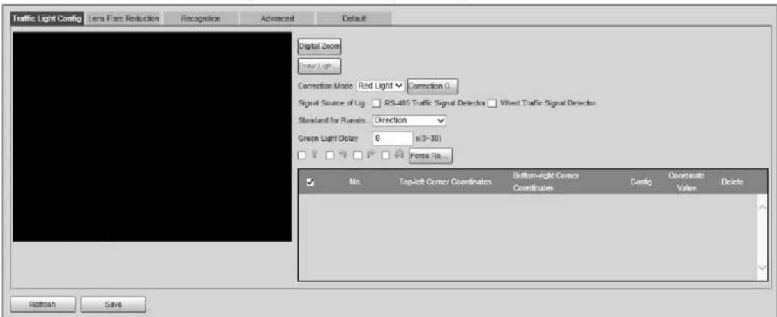
Step 2 Click Digital Zoom, and then use the mouse to select an area that includes the traffic lights. The area is zoomed into.
Step 3 Click Draw Light Group Area, and then use the mouse to draw a frame around the traffic lights.
Step 4 Configure the parameters.
Table 4-21 Description of traffic light parameters
| Parameter Description | |
| Correction Mode | Red Light Correction: Correct the image color according to the red light signal.Force Correction: Correct the image color directly. |
| Correction Config | Click Correction Config to configure correction parameters.Select Image Correction or Video Correction to determine whether you need to correct images or videos.Configure the level of correction for day and night.Click OK |
| Signal Source of Light Group | RS-485 Traffic Signal Detector: Synchronize external traffic light signals such as signal detectors and traffic light detectors to the current traffic lights.Wired Traffic Signal Detector: Synchronize the traffic light scheme of the traffic signal controller to the current traffic lights. |
| Standard for Running-Red-Light | Capture running a red light depending on the lane direction or travelling direction. At present, three ways are supported: Lane direction, travelling direction, and lane/travelling direction. |
| Green Light Delay | Do not capture the illegal act of running a red light within seconds after the red light turns on. |
| Force Red Light | Force the traffic light of the corresponding direction to red. |
Step 5 Click Save.
Lens Flare Reduction
To reduce the influence of other light sources and improve the recognition rate, you can reduce the halo.
Step 1 Select Setting > ITC > E Police > Intelligent Analysis > Lens Flare Reduction.
Figure 4-36 Lens flare reduction
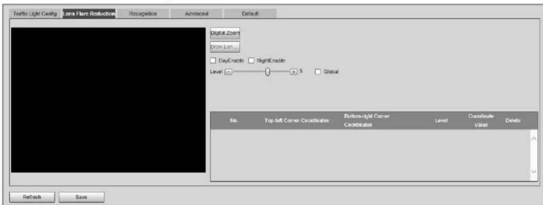
Step 2 Click Digital Zoom, and then select an area for lens flare reduction on the image.
Step 3 Click Draw Lens Flare Area, and then click and drag to select the light source with halo on the image.
Step 4 Configure the parameters.
Table 4-22 Description of lens flare reduction parameters
| Parameter Description | |
| DayEnable | Enable lens flare reduction for daytime. |
| NightEnable | Enable lens flare reduction for nighttime. |
| Level | The level of halation control. The smaller the value, the more obvious the effect. |
| Global | Apply the same halation control level to all the selected areas. |
Step 5 Click Save.
Recognition
Step 1 Select Setting > ITC > E Police > Intelligent Analysis > Recognition.
Step 2 Configure the parameters.
Figure 4-37 Recognition
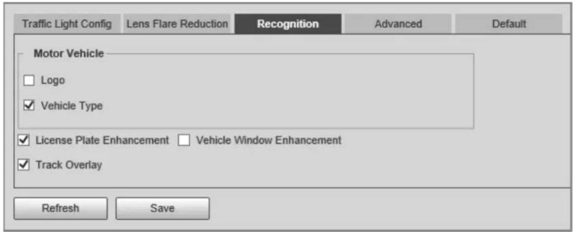
Table 4-23 Description of recognition parameters
| Parameter Description | |
| Motor Vehicle | Supports recognizing vehicle logs and vehicle types. |
| License Plate Enhancement | Select the checkbox to enhance the effect of license plate images. |
| Vehicle Window Enhancement | Select the checkbox to enhance the effect of vehicle window images. |
| Track Overlay | Select the checkbox to enable Track Overlay. After you enable the function and click 📄 on the Live page, you can see that each vehicle is covered by a green box. |
Step 3 Click Save.
Advanced
Step 1 Select Setting > ITC > E Police > Intelligent Analysis > Advanced.
Step 2 Configure a custom algorithm.
Step 3 Click Save.
Default
Step 1 Select Setting > ITC > E Police > Intelligent Analysis > Default.
Step 2 Click Default to restore settings including lane property, violation capture, and intelligent business to default.
4.5.1.3.3 Configuring Original Picture OSD
Configure OSD content, style, and position for captured images.
Step 1 Select Setting > ITC > E Police > Original Picture OSD.
Step 2 Configure OSD black edge position, black region height, OSD separator, and front size.
Figure 4-38 Original picture OSD
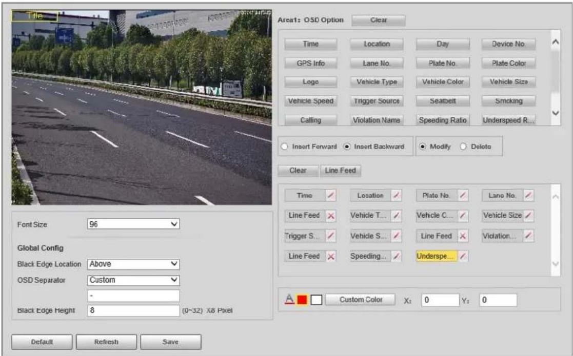
Step 3 Configure the OSD parameters.
Table 4-24 Description of OSD parameters
| Parameter Description | |
| Insert Forward | Select an OSD option, select Insert Forward, and then select another OSD option. The new OSD option will be inserted before the original one. |
| Insert Backward | Select an OSD option, select Insert Backward, and then select another OSD option. The new OSD option will be inserted after the original one. |
| Modify | Select Modify, and then √ is displayed next to all the selected OSD options. To edit an OSD option, click √ next to the OSD option. |
| Delete | Select Delete, and then ✗ is displayed next to all the selected OSD options. To delete an OSD option, click ✗ next to the OSD option. |
| Clear | Delete all the selected OSD options. |
| Line Feed | To start a new line after an OSD option, select the OSD option, and then click Line Feed. |
Step 4 Click Save.
4.5.1.3.4 Configuring Combination Picture OSD
Step 1 Select Setting > ITC > E Police > Combination Picture OSD.
Step 2 Configure OSD black edge position, black region height, OSD separator, and front size.
Step 3 Configure the OSD parameters. For details, see Table 4-24.
Step 4 Click Save.
4.5.1.3.5 Configuring Cutout
Step 1 Select Setting > ITC > E Police > Cutout Config.
Step 2 Select the cutout type.
Figure 4-39 Cutout config
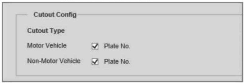
Step 3 Click Save.
4.5.1.4 Composition & OSD
4.5.1.4.1 Configuring Picture Synthesis
Select violation types and set the combination sequence, picture size, and other parameters to form an image combined with the information you set.
Step 1 Select Setting > ITC > Composition & OSD > Picture Synthesis.
Figure 4-40 Picture synthesis
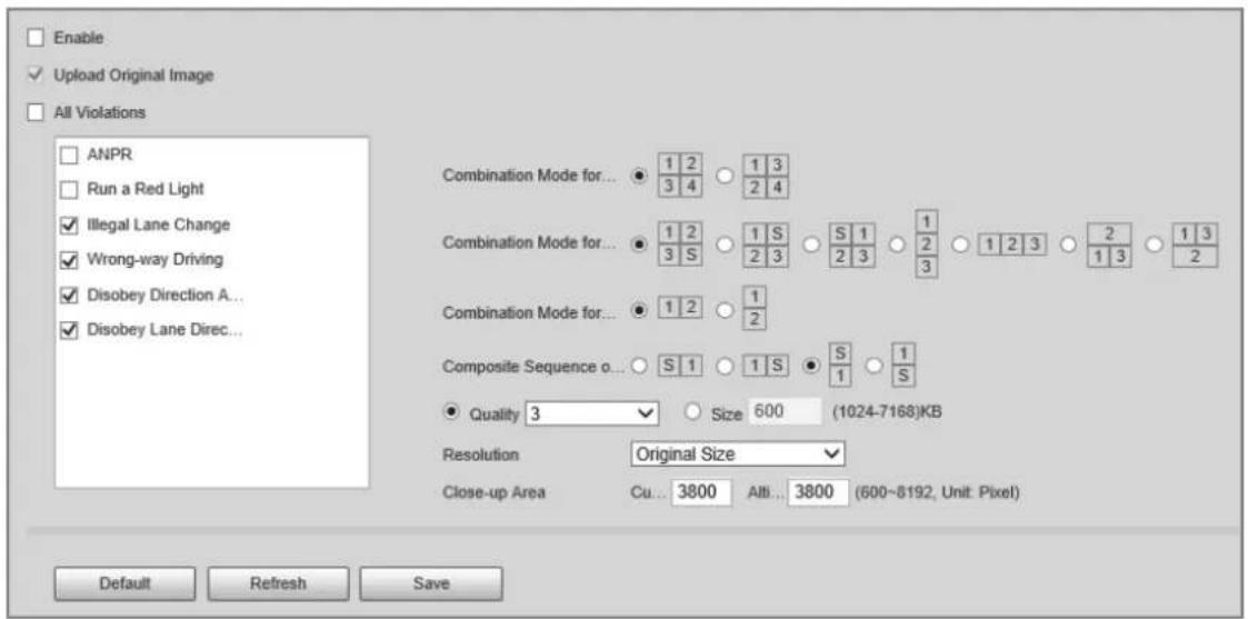
Step 2 Select Enable to enable image mosaic.
Step 3 Select Upload Original Image as needed. If you do not select this checkbox, no original image is uploaded.
Step 4 Under All Violations, select one or more violation types.
Step 5 Configure other parameters.
Table 4-25 Description of combination parameters
| Parameter Description | |
| Combination Mode for X Pictures | Select the combination mode for 2, 3, or 4 images. |
| Composite Sequence of One Picture | Select the combination mode for 1 image. |
| Quality | Select Quality, and then you can set the quality of the images. |
| Size | Select Size, and then you can set the maximum size of the images. |
| Close-up Area | Customized Width: the width of the close-up area.Altitude: the height of the close-up area. |
Step 6 Click Save.
4.5.1.4.2 Configuring Video OSD
Step 1 Select Setting > ITC > Composition & OSD > Video OSD.
Step 2 Click Channel Title, and then click Enable to enable the OSD type.
Figure 4-41 Video OSD
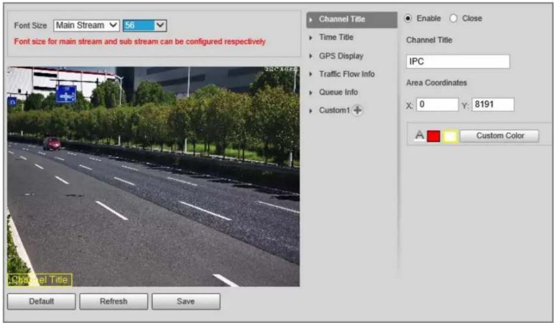

You can add information including channel, time, GPS, traffic flow, queue information, and custom content as OSD information. In this section, Channel Title is used as an example.
Step 3 Set the channel title, coordinates, font size, and font color.
You can also drag the OSD box on the image to change the position of channel title.
Step 4 (Optional) Click + next to Custom1 to add custom OSD information.

You can add up to 8 pieces of custom OSD information.
Step 5 Click Save.
4.5.1.5 Transfer Offline
After you enable transfer offline, the Device will continue to upload the images captured during the offline period to the platform when the Device is reconnected to the platform after disconnection.
Step 1 Select Setting > ITC > Transfer Offline.
Step 2 Select ANR to enable the function.
Figure 4-42 ANR
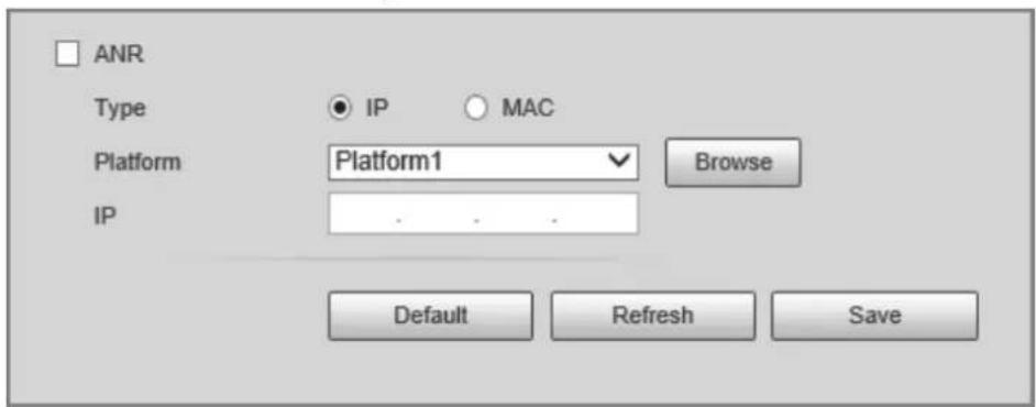
Step 3 Configure the parameters.
Table 4-26 Description of ANR parameters
| Parameter Description | |
| Type | IP: The system identifies the platform through IP address.MAC: The system identifies the platform through MAC address. |
| Platform | Select a platform to upload images. ClickBrowseto search for current online platforms. |
| IP/MAC Address | If IP is selected, enter the IP address of the platform.IfMACis selected, enter the MAC address of the platform. |
Step 4 Click Save.
Step 5 Click Manual Upload, select a platform and enter its IP address or MAC address, select image types, and then set a time period to upload images captured during the defined time period to the specified platform.
Figure 4-43 Manual upload
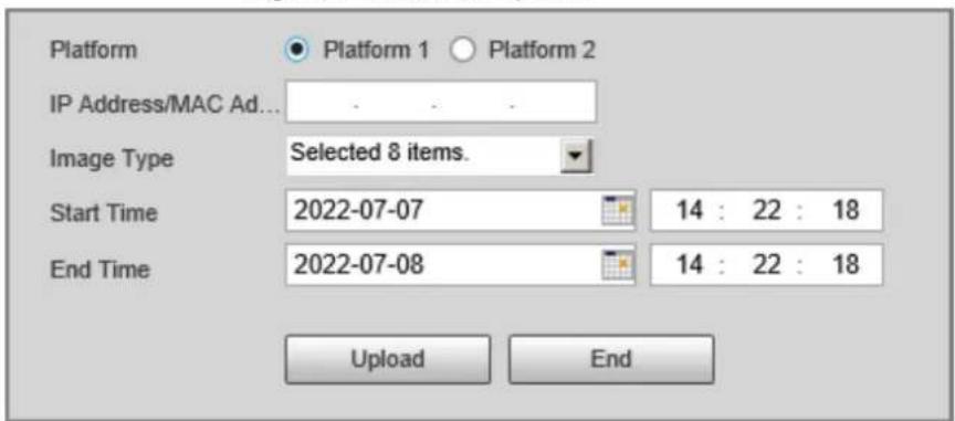
Step 6 Click Upload.
During the upload, you can click End to stop uploading.
4.5.1.6 Vehicle Allowlist/Blocklist
Set the allowlist and blocklist of vehicles.
- Allowlist: When vehicles on the allowlist are detected, the Device discards the captured vehicle violation images without any processing.
- Blocklist: When vehicles on the blocklist are detected, the Device triggers linked actions.
4.5.1.6.1 Setting Allowlist
Step 1 Select Setting > ITC > Vehicle Allowlist/Blocklist > Allowlist.
Step 2 Set an allowlist.
- Add one by one.
- Click Add.
- Set filter conditions and details.
Figure 4-44 Add a plate number to the allowlist
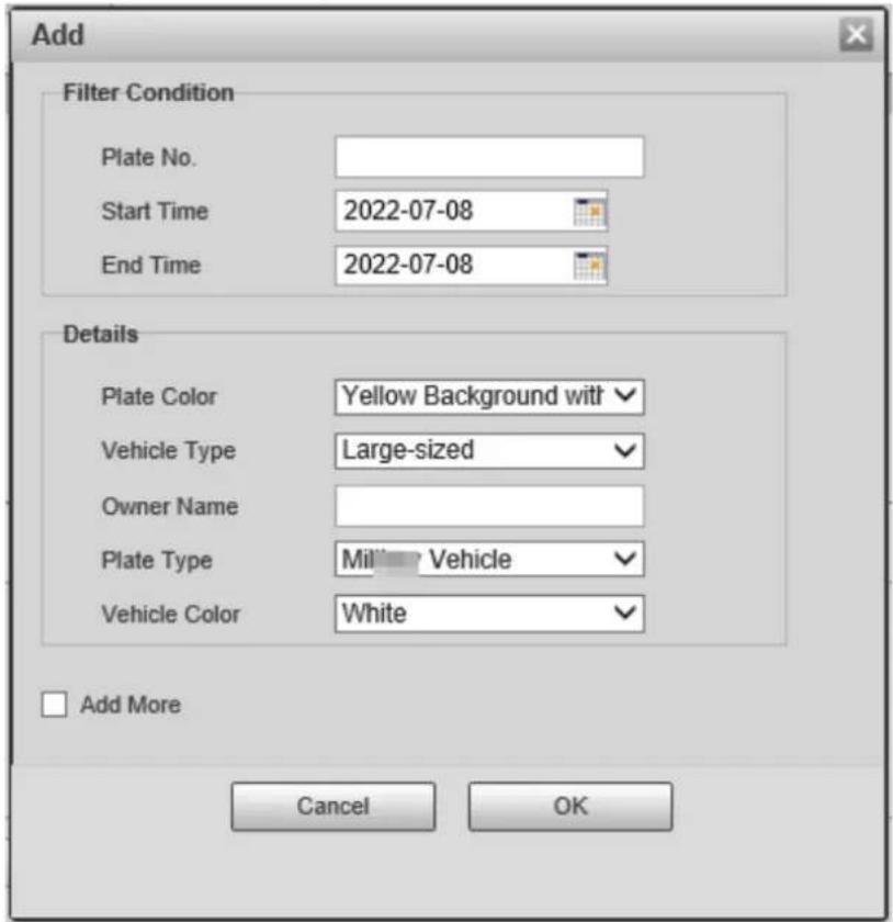
- Click OK.

Select Add More, and then you can continue to add more plate numbers after you click OK.
- Add in batches.
- Click Export to download an allowlist template.
- Fill in the allowlist template.
Table 4-27 Allowlist template
| Start Time | End Time | Owner Name | Plate Color | Plate No. | Plate Type | Vehicle Color | Vehicle Type |
| 2022/7/8 00:00 | 2022/7/8 23:59 | Ana 1 A**** 3 A 1 | |||||
-
Click Browse, and then select the allowlist template that you want to import.
-
Click Import to import the allowlist template.
4.5.1.6.2 Setting Blocklist
Select Setting > ITC > Vehicle Blocklist/Allowlist > Blocklist. The setting of a blocklist is similar to that of an allowlist. For details, see "4.5.1.6.1 Setting Allowlist".
4.5.1.7 Traffic Flow
You can configure traffic flow parameters, including statistical cycle and flow upper limit.
Step 1 Select Setting > ITC > Traffic Flow > Flow Statistics.
Step 2 Configure the parameters.
Figure 4-45 Flow statistics
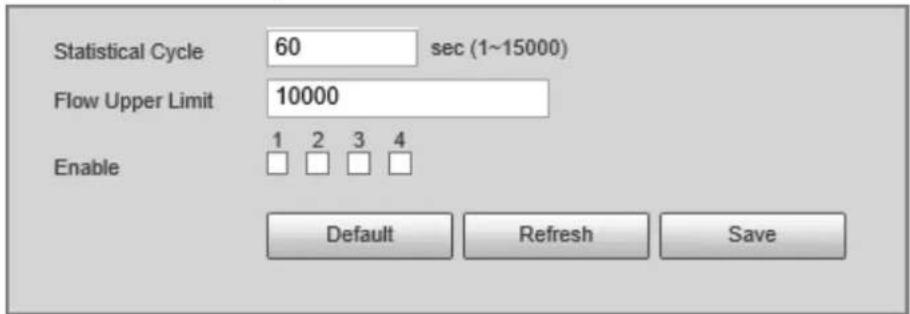
Table 4-28 Description of traffic flow parameters
| Parameter Description | |
| Statistical Cycle The statistical cycle of traffic flow. | |
| Flow Upper Limit | The upper limit of traffic flow. If the actual traffic flow data exceeds the upper limit, the upper limit is used as the traffic flow data. |
| Enable | Select a checkbox to enable traffic flow statistics for corresponding lane. |
Step 3 Click Save.
Step 4 Click Flow Data, and then you can view real-time traffic flow data.
- Click to clear traffic flow data.
- Click Export to export traffic flow data.
Figure 4-46 Flow data
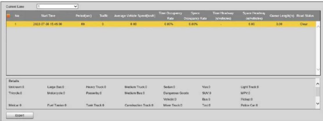
4.5.1.8 Watermark
You can verify whether local images and videos were tampered with by checking the watermark.
4.5.1.8.1 Verifying Images
Step 1 Select Setting > ITC > Watermark > Picture.
Step 2 Click Path, select a folder where the images to be verified is located, and then click OK,
Figure 4-47 Image watermark verification
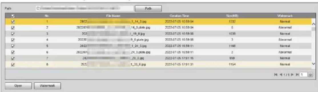
Step 3 Select one or more images from the list, and then click Watermark.
- If Normal is displayed in the Watermark column, the image is not tampered.
- If Abnormal is displayed in the Watermark column, the image is tampered.
Step 4 (Optional) Click Open to open the selected image.
4.5.1.8.2 Verifying Videos
Step 1 Select Setting > ITC > Watermark > Video.
Step 2 Click Select File, and then select a video to be verified.
Step 3 Click Watermark.
- If the video is not tampered, the watermark is displayed next to Watermark Info.
- If the video is tampered, you can check the details in Tampered Watermark Info.
Figure 4-48 Video watermark verification
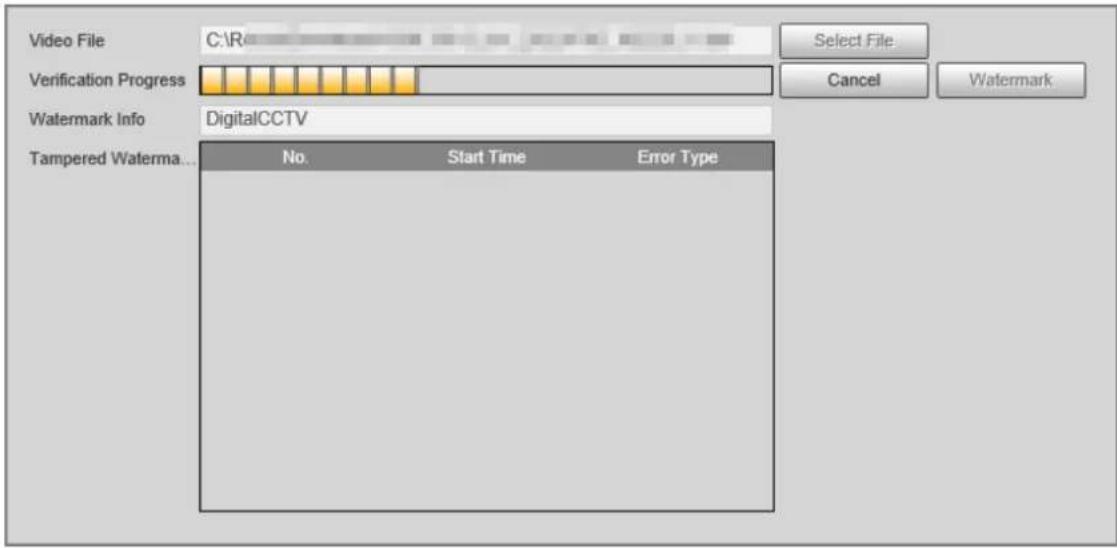
4.5.2 Camera
You can configure camera attributes such as the attributes of videos and images.
4.5.2.1 Image
4.5.2.1.1 Configuring General Parameters
Step 1 Select Setting > Camera > Image > General.
Figure 4-49 General
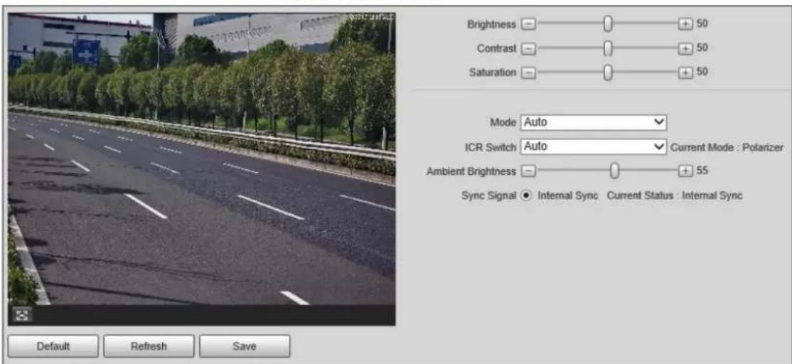
Step 2 Configure the parameters.
Table 4-29 Description of general parameters
| Parameter Description | |
| Brightness | Both the darker areas and the brighter areas will be changed together when adjusting the brightness.The image might become blurry when the value gets bigger. The recommended range is 40–60, and the available range is 0–100.It is 50 by default. The larger the value, the brighter the image. |
| Contrast | The larger the value, the darker the dark area, and the more exposed the bright area.The image might become blurry when the value gets smaller. The recommended range is 40–60, and the available range is 0–100.It is 50 by default. The larger the value, the stronger the contrast. |
| Saturation | The saturation value does not change the overall image brightness.The larger the value, the more saturated the image. The recommended range is 40–60, and the available range is 0–100.It is 50 by default. |
| Mode | Color: The image is always colored.Auto: When the brightness is higher than the preset value, the image automatically changes to color. When it is below the preset value, the image changes to black and white.B/W: The image is always black and white. |
| ICR Switch | Auto: You need to pre-set the brightness in this mode. When the ambient brightness is higher than the preset value, the polarizer will start to work.Polarizer: The polarizer is always running. Applicable to scenarios with high brightness.IR Mode: Applicable to scenarios with low brightness. |
| Ambient Brightness | The ambient brightness of ICR switch.This parameter is available only when you set ICR Switch to Auto. |
4.5.2.1.2 Configuring Shutter
You can configure shutter mode, exposure mode, and gain mode.
Step 1 Select Setting > Camera > Image > Shutter.
Figure 4-50 Shutter
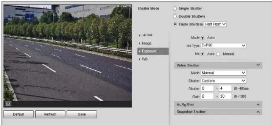
Step 2 Click Video Shutter, Snapshot Shutter, or Recognition Shutter to show the parameters related to the shutter. To configure the parameters, refer to the table below.

Recognition Shutter is only available in Triple Shutters mode.
Table 4-30 Shutter parameters
| Module Parameter Description | ||
| Shutter Mode | Single Shutter | Video and snapshot share the same exposure mode. |
| Double Shutters | Video Shutter and Snapshot Shutter can be separately configured.Half Frame Rate: Video and snapshot take half of the frame respectively.Full Frame Rate: Snapshot takes 1 frame, and video takes the rest of the frames. | |
| Triple Shutters | Video Shutter and Snapshot Shutter can be separately configured, and Recognition Shutter is added.Triple Shutter mode is available only when General Mode is selected as Capture and Flash Linkage from Setting >ITC >E Police >Other Config. | |
| 3D NR | Video/Image 3D NR | When it is Enable, 3D NR is enabled to reduce noise of video/image. |
| Video/Image Spatial 3D NR | Spatial video/snapshot denoising. The higher the value, the less the noise. | |
| Video/Image Temporal 3D NR | Temporal video/snapshot denoising. The higher the value, the less the flicker noise. | |
| Image | Scene | You can change the scene and adjust the sharpness of the corresponding scene. Scenes available: Morning/Dusk, Day, and Night. |
| Sharpness | You can set the sharpness of the corresponding scene.The higher the value, the clearer the image. But there will be noise if the sharpness is too high. | |
| WDR | Select Enable to enable WDR (wide dynamic range), which helps provide clear video images in bright and dark light. | |
| Exposure | Mode Only | Auto mode is available. |
| Iris Type | Displays the detected iris type. | |
| Mode | Select the way of adjusting exposure mode. You can select from Manual and Auto. | |
| Shutter | You can select the shutter value, or select Custom, and then set the shutter range. You need to configure shutter when Mode is set to Manual. You need to configure shutter when Mode is set to Manual. | |
| Shutter | Set the time range of shutter. You need to configure shutter when Shutter is set to Custom. You need to configure shutter when Shutter is set to Custom. | |
| Gain | Set the value range of gain. You need to configure gain scope when Mode is set to Manual. You need to configure gain scope when Mode is set to Manual. | |
| WB | Mode | Set scene mode to adjust the image to its best status. |
Step 3 Click Save.
4.5.2.1.3 Configuring Metering Zone
Set the measure mode of metering zone.
Step 1 Select Setting > Camera > Image > Metering.
Figure 4-51 Metering
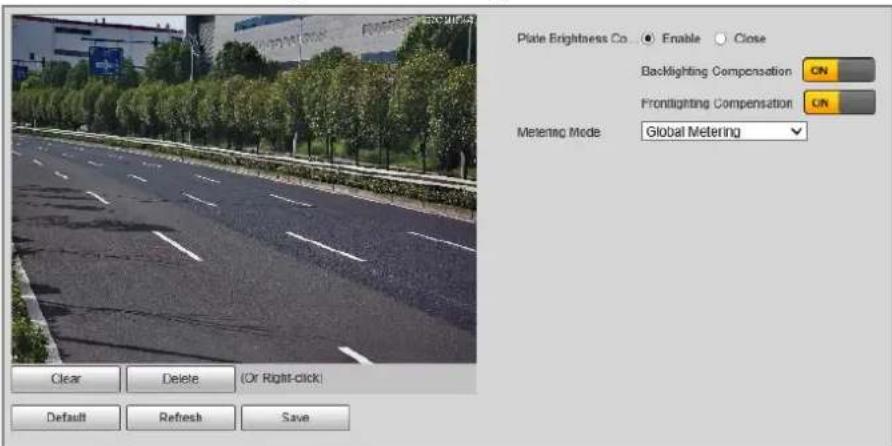
Step 2 Configure the parameters.
Table 4-31 Desription of metering parameters
| Parameter Description | |
| Plate Brightness Compensation | When selecting Enable, you can turn ON backlight and frontlight according to scene requirements to improve the backlight and frontlight image brightness. |
| Backlight Compensation | |
| Frontlight Compensation | |
| Metering Mode | Global Metering: Measure the brightness of the whole image area and intelligently adjust the overall image brightness.Partial Metering: Measure the brightness of selected areas and intelligently adjust the overall image brightness. If the measured area becomes bright, then the whole area becomes dark, and vice versa.1. Drag the mouse to select the measured area and a yellow box displays over the video image.2. Drag the box to a proper location, and then click Save. |
Step 3 Click Save.
4.5.2.2 Video
After connecting the Device to the network and viewing the real-time video on the webpage, you can configure encoding parameters when necessary to obtain clear and smooth video.
4.5.2.2.1 Configuring Video Parameters
Configure the parameters of video streams.
Step 1 Select Setting > Camera > Video > Video Stream.
Figure 4-52 Video stream
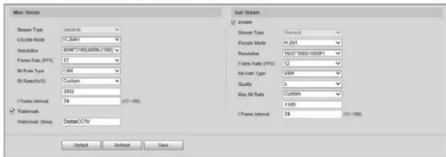
Step 2 Configure the parameters.
Table 4-32 Video stream parameters
| Parameter Description | |
| Encode Mode | You can select H.264B, H.264, H.264H, MJPEG, or H.265. |
| Resolution | The higher the value, the clearer the overall image. For each resolution, the recommended bit stream value is different.The resolution of sub stream cannot be greater than that of main stream. |
| Frame Rate (FPS) | The higher the value, the smoother the video image. The frame rate might vary due to different resolutions. |
| Bit Rate Type | You can select from VBR (variable bitrate) and CBR (constant bitrate).VBR: Gives the best balance between quality and file size as the bitrate can be altered depending on the video.CBR: Keeps the bitrate the same during encoding, and we recommend you use this bitrate type when the network connection is limited to performing at, for example, 320 Kbps. |
| Quality | 6 quality levels are available. The higher the value, the better the quality.You need to configure the image quality when Bit Rate Type is set to VBR. |
| Bit Rate(Kb/S) | Higher bit rate signifies greater image or video quality, but also occupies more storage space.You need to configure the bit rate when CBR is set to Bit Rate Type. |
| Max. Bit Rate | It is the upper limit of stream in VBR. In CBR, the value is fixed. |
| I Frame Interval | The number of P-frame between two I-frames. The number varies according to the bit rate. The range is 12–150. We recommend you configure the value to be twice the amount of the bit rate. |
| Watermark | You can verify the watermark to check whether the video has been tampered.Select the Watermark checkbox to enable watermark verification. The watermark character is DigitalCCTV by default.Watermark character consists of up to 85 characters with numbers, letters and underlines. |
| Enable | Enable sub stream when your network bandwidth is insufficient or other conditions influence the video smoothness in main stream. |
Step 3 Click Save.
4.5.2.2.2 Configuring ROI
Set the region of interest in the image, and then the selected region will be displayed with the configured quality.
Step 1 Select Setting > Camera > Video > ROI.
Figure 4-53 ROI
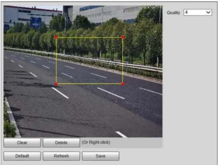
Step 2 Drag anywhere in the image to draw the region of interest. You can draw more than one region when necessary.

You can click Clear to delete all the regions of interest, or click Delete or right-click on the video image to delete the most recently drawn area.
Step 3 Set the image quality of the regions of interest. 6 quality levels are available. The higher the value, the better the quality.
Step 4 Click Save.
4.5.3 Network Settings
You can configure network parameters such as IP address, subnet mask, and default gateway.
4.5.3.1 Configuring TCP/IP
You can configure host name, IP address, and more.

Some models are designed with 2 network ports. Do not configure the ports to be on the same network segment; otherwise, the network might fail.
Step 1 Select Setting > Network Settings > TCP/IP.
Figure 4-54 TCP/IP
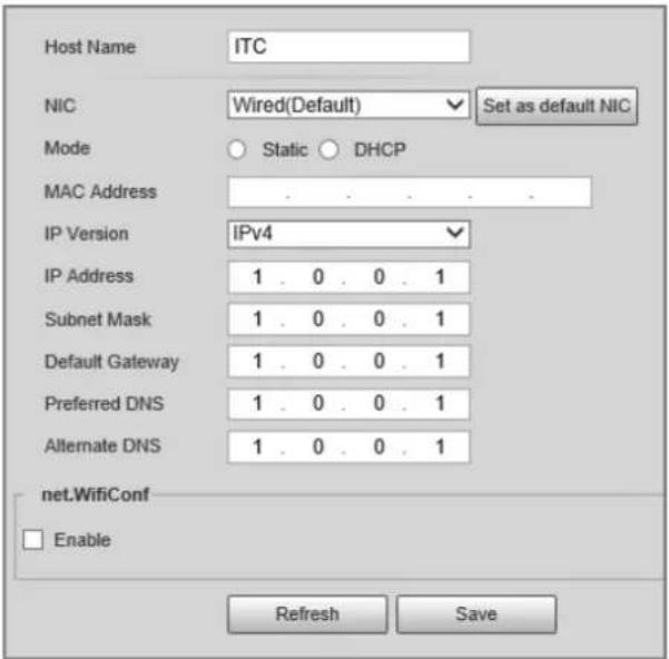
Step 2 Configure the parameters.
Table 4-33 Description of TCP/IP parameters
| Parameter Description | |
| Host Name | Configure the host name (not exceeding 15 characters). |
| NIC Supports wired network only. | |
| Mode | DHCP: The Device automatically assigns IP addresses. In this case, the IP Address, Subnet Mask, and Default Gateway cannot be configured.Static: The IP Address, Subnet Mask, and Default Gateway need to be manually configured. |
| MAC Address | Displays host MAC address. |
| IP Version | IPv4 and IPv6 are available. Both IP versions can be accessed. |
| IP Address The IP address of the Device. | |
| Subnet Mask | The subnet mask that masks the IP address of the Device. |
| Default Gateway | The default gateway corresponding to IP address of the Device. |
| Preferred DNS | The IP address of preferred DNS. |
| Alternate DNS | The IP address of alternate DNS. |
| net.Wifi.Conf | Select Enable to enable Wi-Fi.SSID: the name of the Wi-Fi network.Password: the password of the Wi-Fi network. |
Step 3 Click Save.
4.5.3.2 Port
4.5.3.2.1 Configuring Port
You can set the port information. Then, you can access the Device through different protocols or configuration tools.
Step 1 Select Setting > Network Settings > Port > Port.
Figure 4-55 Port
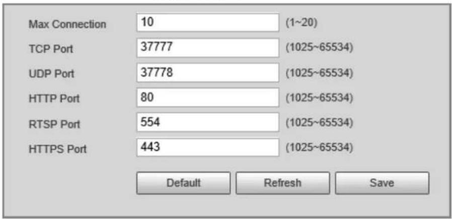
Step 2 Configure the port number of the Device for each protocol.
Table 4-34 Description of port parameters
| Parameter Description | |
| Max Connection | The maximum number of clients (such as web client and platform client) that are allowed to access the Device simultaneously. It is 10 by default. |
| TCP Port | TCP protocol communication port. It is 37777 by default. |
| UDP Port | User data packet protocol port. It is 37778 by default. |
| HTTP Port | HTTP communication port. It is 80 by default. |
| RTSP Port | Media streaming control port. It is 554 by default. |
| HTTPS Port HTTPS communication port. It is 443 by default. | |
Step 3 Click Save.
4.5.3.2.2 Configuring ONVIF
Open Network Video Interface Forum (ONVIF) is an open industry forum with the goal of providing and promoting standardized pages for interoperability of physical IP-based security products, such as IP camera, and network recorder, and more.
Select Setting > Network Settings > Port > ONVIF. Verification of username and password will be required for logging in to ONVIF when ONVIF authentication is turned on.
Figure 4-56 ONVIF
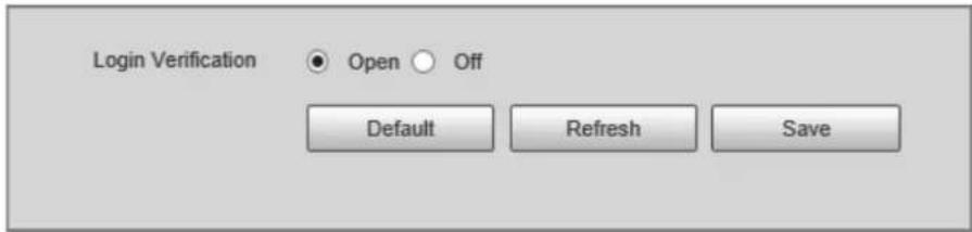
4.5.3.2.3 Configuring Auto Registration
When the Device is connected to the network, it will automatically report its location to the server specified by the user. This helps client software to access the Device through the server for viewing and monitoring the real-time video.
Step 1 Select Setting > Network Settings > Register.
Step 2 Select the Enable checkbox to enable auto registration function.
Step 3 Enter the IP address of server that needs to be registered, and also the port for auto registration.
Step 4 Enter the Sub-Device ID, which is the device ID assigned by the server for auto registration. Make sure that there are no repeated device IPs.
Step 5 Click Save.
Figure 4-57 Register
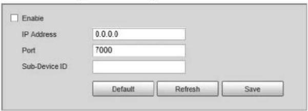
4.5.3.2.4 Configuring 802.1x
Step 1 Select Setting > Network Settings > 802.1x.
Figure 4-58 802.1x
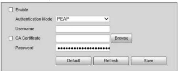
Step 2 Select Enable to enable 802.1x, and then configure the parameters.
Table 4-35 Description of 802.1x parameters
| Module Parameter Description | ||
| Common Parameter | Authentication Mode | PEAP: Ordinarily uses TLS only to authenticate the server to the client, and only the sever is required to have a public key certificate.EAP-TLS: Provides mutual authentication of client to server, and server to client. Both the client, and the server must be assigned a digital certificate signed by a CA (Certificate Authority) that they both trust. |
| CA Certificate | ClickBrowseto import a CA certificate and then select the CACertificate to verify whether the certificate is valid. | |
| PEAP | Username | For PEAP method, user authentication is performed by using password-based credentials (username, and password). |
| Password | ||
| EAP-TLS | Client Certificate | ClickBrowseto import a client certificate and a private key for authentication. |
| Private Key | ||
Step 3 Click Save.
4.5.4 Event
4.5.4.1 Exception
An alarm will be triggered when an abnormal event occurs. The event types include:
- Disk Abnormal: An alarm will be triggered when there is No SD card, SD card error, or Memory insufficient.
- Network Exception: An alarm will be triggered when there is Offline (the Device is offline) or IP Conflict.
- Invalid Access: An alarm will be triggered when unauthorized access is detected by the system.
• Security Exception: An alarm will be triggered when security problem occurs.
Step 1 Select Setting > Event > Exception

The following figure uses Disk Abnormal as an example. For other events, refer to the actual page.
Step 2 Configure the parameters.
Figure 4-59 Disk Abnormal
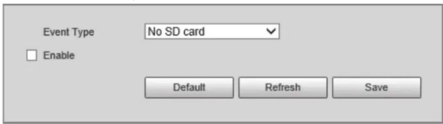

Refer to the actual page to view the parameters that you need to configure for each exception.
Table 4-36 Description of exception parameters
| Parameter Description | |
| Enable | Select it to enable alarm of abnormal events. |
| Login Attempt | Configure the number of login errors allowed. The range is 3–10 times. |
Step 3 Click Save.
4.5.4.2 Device Location
You can view the device position information, such as its longitude and latitude. Select Setting > Event > Device Location.
4.5.5 Peripheral
4.5.5.1 Device Status
Select Setting > Peripheral > Peripheral > Device Status, and then you can view the information of external devices.
4.5.5.2 External Light
You can configure the work mode of the flashing lights and strobes connected to the Device. Step 1 Select Setting > Peripheral > Peripheral > External Light.
Figure 4-60 Light config
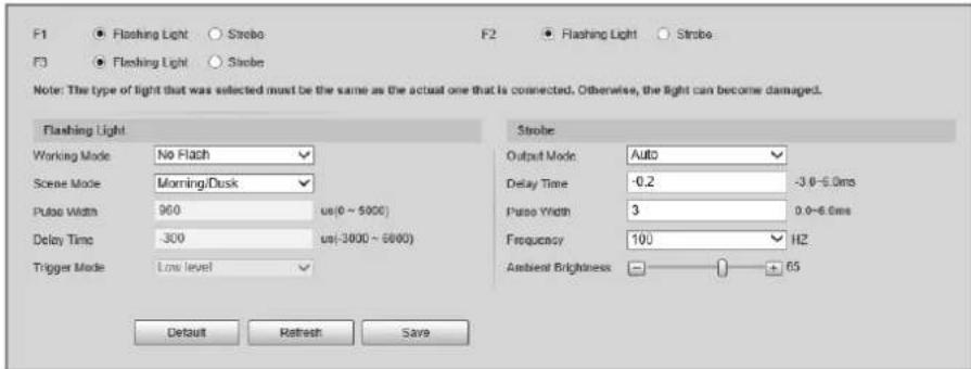
Step 2 Configure the parameters.
Table 4-37 Description of light parameters
| Parameter Description | ||
| F1/2/3 | Select the light type connected to each port.The light type must be the same as the actual connected light type. Otherwise, the light might be damaged. | |
| Flashing Light | Working Mode | No Flash: The light is normally off.Always Flash: The light is normally on.Auto Flash: Configure the preset value of brightness. If the ambient brightness is lower, the light automatically turns on; if higher, the light automatically turns off. |
| Scene Mode | Select the scene mode for the flashing light from Morning/Dusk, Day and Night, indicating different brightness of the light which suits the environment the best. | |
| Pulse Width | Configure the pulse width of flashing light. The higher the value, the brighter the light. | |
| Delay Time | Configure the delay time of the light to keep the snapshot in sync with the flash. | |
| Trigger Mode | You can select the level that triggers the flashing light. Currently, only Low level is supported. | |
| Strobe | Output Mode Same as Working Mode of flashing light. | |
| Frequency | Set the frequency of the strobe. | |
| Ambient Brightness | When setting Output Mode to Auto, you need to set the ambient brightness. | |
Step 3 Click Save.
4.5.6 Storage
You can configure the storage path of snapshots and recorded videos.
4.5.6.1 Storage Spot Config
Step 1 Select Setting > Storage > Storage > Storage Spot Config.
Figure 4-61 Storage spot config
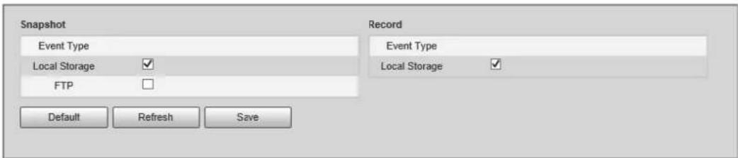
Step 2 Select storage path as needed.
- Local Storage: Store in the TF card, which has a limited capacity but offers continuous
access to its storage, even during network failure. Videos can only be stored in TF card.
- FTP: Store in the FTP server, which offers a greater capacity but it will stop storing when the network fails.
Step 3 Click Save.
4.5.6.2 Local Storage
Select Setting > Storage > Storage > Local Storage
You can format the TF card, or select to Overwrite or Stop storage when the disk is full. Click Save after these operations.

Make sure that a TF card is inserted. Otherwise, no card information will be displayed on the Local Storage tab.
Figure 4-62 Local storage
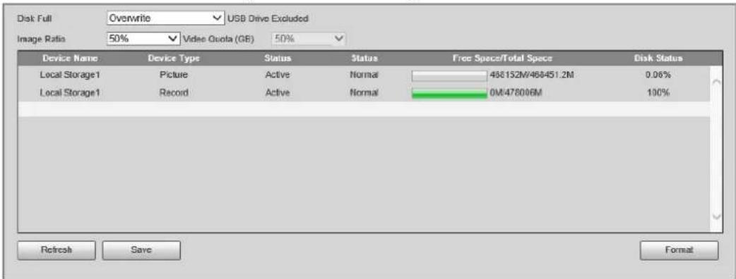
4.5.6.3 FTP
FTP function can be enabled only when TF card is inserted and FTP server is enabled. Only snapshots can be saved to the FTP server.
Step 1 Select Setting > Storage > Storage > FTP.
Figure 4-63 FTP
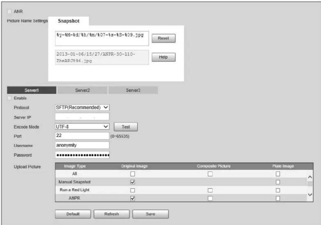
Step 2 Configure the parameters.
Table 4-38 Description of FTP parameters
| Parameter Description | |
| ANR | When the network disconnects or fails, snapshots will be stored in TF card. After the network is restored, the snapshots will be uploaded from the TF card to FTP or client.Make sure that TF card is inserted in the Device; otherwise, the offline transfer function cannot be enabled. |
| Picture Name Settings | Set the naming rule of snapshots to be saved in FTP server. You can click Help to view the Image Naming Rules, or click Reset to restore the default naming rule. |
| Server1, Server2, Server3 | Supports uploading to multiple servers. You can save different types of snapshots to different servers. Select the snapshot types from Upload Picture. |
| Enable Enable FTP server | storage. |
| Protocol | SFTP: Secure File Transfer Protocol, a network protocol that allows file access and transfer over a secure data stream.FTP: File Transfer Protocol, a network protocol implemented to exchange files over a TCP/IP network. Anonymous user access is also available through an FTP server. |
| Server IP | The IP address of FTP server. |
| Encode Mode | The encode mode of Chinese characters when naming images. Only UTF-8 is supported. After configuring Server IP and Port, click Test to check whether the FTP server works. |
| Port | The port number of FTP server. |
| Username, Password The | username and password of FTP server. |
| Upload Picture | Select events and picture types to be uploaded to each FTP server. Different modes support different events, and might differ from the actual page. |
Step 3 Click Save.
4.5.6.4 Storage Path
You can configure the names and storage paths of snapshots and recorded videos.
Step 1 Select Setting > Storage > Storage > Storage Path.
Step 2 Name the snapshots in the Naming Format section. You can click Help to view the Image
Naming Rules, or click Reset to restore the naming rule to the default.
After setting the naming rule, you can preview an example of the name in theName Preview section.
Step 3 Click Browse to set the storage paths of snapshots and recorded videos respectively.
Step 4 Click Save.
Figure 4-64 Storage path
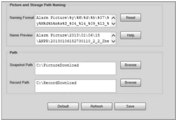
4.5.6.5 SMART
SMART (Self-Monitoring Analysis and Reporting Technology) is used to display automatic disk detection results, and discover and predict possible disk problems in time.
Step 1 Select Setting > Storage > Storage > S.M.A.R.T.
Step 2 Check the information and health state of the disk.
4.5.7 Record
4.5.7.1 Record Control
Step 1 Select Setting > Storage > Storage > Record Control.
Step 2 Select the record mode.
• Auto: Record videos continuously
- Violation: Record videos only when a traffic violation event is detected.
- Close: Do not record videos.
Step 3 Select the record stream. You can select Main Stream or Sub Stream.
Step 4 Set the maximum duration of recorded videos.
Step 5 Click Save.
Figure 4-65 Record control
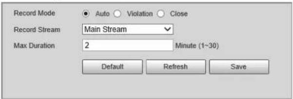
4.5.7.2 Schedule
Step 1 Select Setting > Storage > Record > Schedule.
Figure 4-66 Schedule
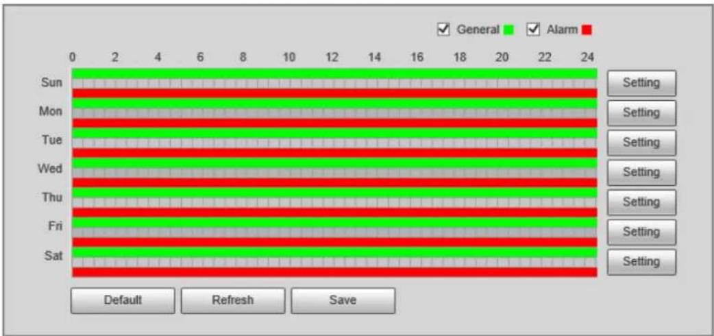
Step 2 Set the record plan records.
- Press and hold the left mouse button, and directly drag to set the period on the timeline corresponding to Sunday to Saturday.
- Click Setting on the right side of Sunday to Saturday. In the Setting dialog box, set periods and record types, and then click OK.
Figure 4-67 Setting
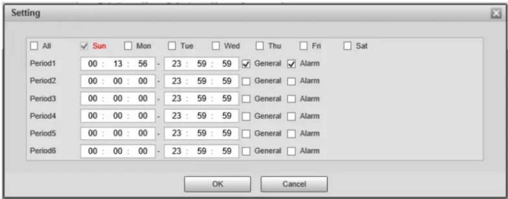
Step 3 Click Save.
4.5.8 System
You can configure system information, add users, restore settings to factory settings, import and export system configuration files, and perform more operations.
4.5.8.1 General
You can configure display language, video standard, and the time and time zone of the Device.
4.5.8.1.1 General Settings
You can configure the device code, system, video standard, and other general settings.
Step 1 Select Setting > System > General > General.
Step 2 Configure the parameters.
Figure 4-68 General
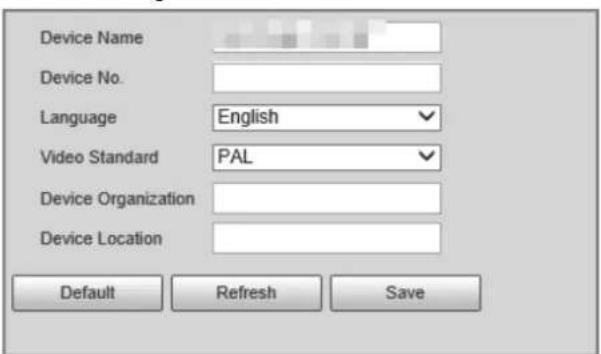
Table 4-39 Description of general parameters
| Parameter Description | |
| Device Name | The name of the Device. |
| Device No. | The sequence number of the Device. |
| Language | The display language of the webpage. You need to log in again when switching to another language. Currently, only English is supported. |
| Video Standard | PAL and NTSC are available.PAL: Much more common around the world, and can be found in most of Western Europe, Australia, China, and elsewhere.NTSC: Mostly limited to North America, parts of South America, Japan, the Philippines and more. |
| Device Organization | The group or entity that uses the Device. |
| Device Location | The location where the Device is installed. |
Step 3 Click Confirm.
4.5.8.1.2 Date & Time
Step 1 Select Setting > System > General > Date & Time.
Step 2 Configure the parameters.
Figure 4-69 Date & time
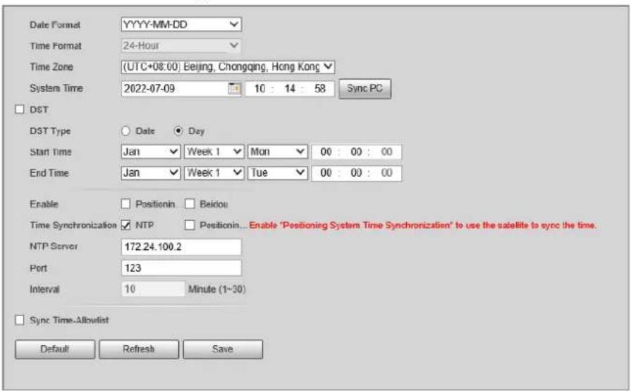
Table 4-40 Description of date & time parameters
| Parameter Description | |
| Date Format | Select the date format. Three formats are available: YYYY-MM-DD, MM-DD-YYYY and DD-MM-YYYY. |
| Time Format | Select the time format. Only 24-Hour is available. |
| Time Zone The time zone where the Device is located. | |
| System Time | The current time of the Device. |
| Sync PC | Synchronize the time of the Device to that of the PC.Click Sync PC, and the settings will immediately take effect. |
| DST | Select the DST checkbox, set the DST Type by Date or by Day, and then configure the Start Time and End Time of DST. |
| Time Synchronization | Time synchronization mode. You can select NTP or Positioning System Time Synchronization. |
| NTP Server | The IP address and the port number of NTP server. |
| Port | Required when NTP is set to Time Synchronization. |
| Interval | The time synchronization interval of the Device and the NTP or satellite. |
| Sync Time-Allowlist | Set the type and IP address that need time synchronization, and then click Add. |
Step 3 Click Save.
4.5.8.2 Account Management
You can add or delete users and user groups, assign permissions to users and user groups, change passwords, and manage users and user groups.
4.5.8.2.1 Account
You can view the information of a user or user group, add or delete users or user groups, change user password, assign user permissions, restrict user login, and perform other operations.
Step 1 Select Setting > System > Account > Account > Username.
Step 2 Add a user.
1) Click Add User.
2) In the Add User dialog box, configure user information including username, password, group name, memo, and operation permissions.
Figure 4-70 Add user
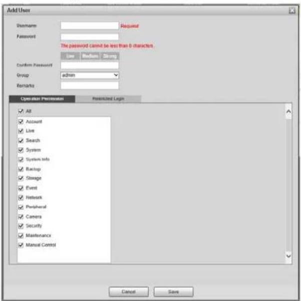
3) Set login restrictions (if necessary), and then the restricted IP address will be unable to log in to the Camera during the restricted period.
Figure 4-71 Set log restriction
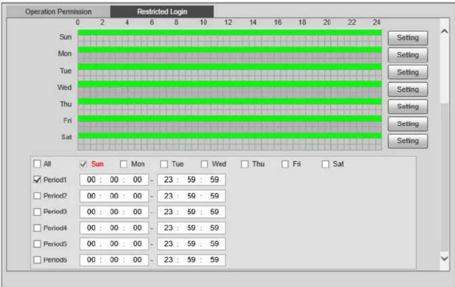
4) Click Save to save the settings.
Step 3 Select Setting > System > Account > Account > Group.
Step 4 Add a group.
1) Click Add Group.
2) Configure the Group and Permission of the group.
3) Click Save.
Related Operations
- Delete a user/user group: Click 🔍 to delete the corresponding user/user group.

◇ The admin and user groups cannot be deleted.
◇ A group cannot be deleted if there is any user in the group.
- Modify user/user group information: Click √ corresponding to the user. You can modify information such as username, password, email address, group name, and memo. Click Save to save the settings.
- Change password: On the Modify User page, select the Change Password checkbox. Enter the old and new passwords, and confirm password. ClickSave after configuration.

The password must consist of 8–32 non-blank characters and contain at least two types of the following characters: Uppercase, lowercase, numbers, and special characters (excluding '" ; : &). Configure the password according to the password strength prompt.
- Clear all user information: Click Clear user under Setting > System > Account > Account > Clear User.
4.5.8.2.2 ONVIF User
ONVIF users can be separately managed from account users and user groups.
- The system manages both ONVIF users and user groups. The factory settings cover one group: admin. You can set up to 18 ONVIF users.
- ONVIF username cannot be repeated. Each ONVIF user must belong to a group, and can only belong to one group. The username can be 31 characters at most, consisting of letters, numbers, " _ ", "@" and ".".
- The default ONVIF username and password are both admin. There is one admin by default which has the highest authority.
Procedure
Step 1 Select Setting > System > Account > ONVIF User.
Step 2 Click Add User.
Step 3 Configure user information such as username, password, and group name.
Figure 4-72 Add user
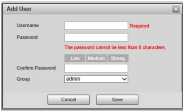
Step 4 Click Save.
Related Operations
- Modify ONVIF user information: Click 📋 corresponding to the user, and then you can modify information such as username, password, and group name.
- Modify password: On the Modify User page, select the Change Password checkbox. Enter the old and new passwords, and confirm password.

The password must consist of 8–32 non-blank characters and contain at least two types of the following characters: Uppercase, lowercase, numbers, and special characters (excluding '"; : &). Configure the password according to the password strength prompt.
4.5.8.3 Security
4.5.8.3.1 System Service
You can enable multiple system services to secure network safety.
Step 1 Select Setting > System > Security > System Service.
Step 2 Enable the services.
Figure 4-73 System service
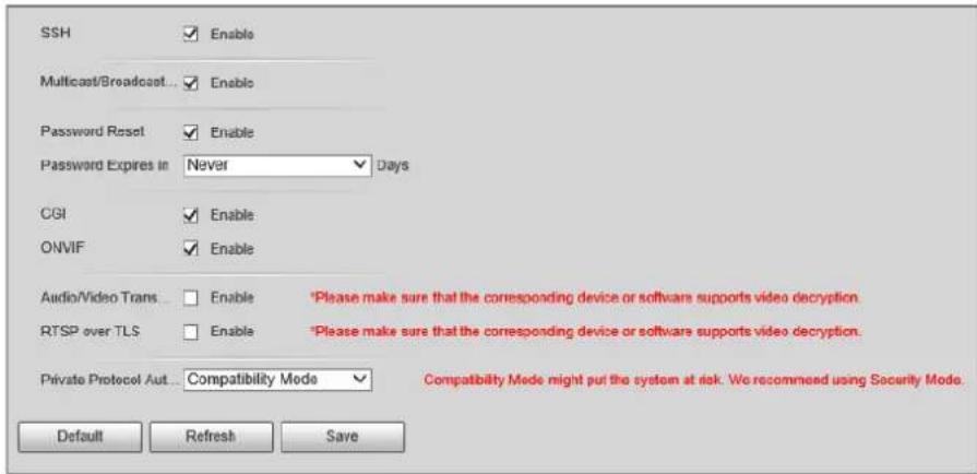
Table 4-41 Description of system service parameters
| Parameter Description | |
| SSH | Secure Shell (SSH) is a cryptographic network protocol for operating network services securely over an unsecure network. It is a method for secure remote login, providing secure access for users. |
| Multicast/Broadcast Search | Multicast identifies logical groups of computers group members. This allows a single message to be sent to the group. Broadcast allows all devices on the same network segment to see the same message. |
| Password Reset | Enable it so that you can reset the password. |
| CGI | Select the Enable checkbox to enable Common Gateway Interface (CGI) service. |
| ONVIF | Select the Enable checkbox to enable Open Network Video Interface Forum (ONVIF) service. |
| Audio/Video Transmission Encryption | Enable this function to encrypt stream transmitted through private protocol.[IMAGE]Make sure that the matched device or software supports the video decryption function.We recommend enabling the encryption service to avoid data leak. |
| RTSP over TLS | Enable this function to encrypt stream transmitted through standard protocol.[IMAGE]Make sure that the matched device or software supports video decryption function.We recommend enabling the encryption service to avoid data leak. |
| Private Protocol Authentication Mode | Security Mode is recommended. |
Step 3 Click Save.
4.5.8.3.2 HTTPS
Prerequisites
- For first-time use of HTTPS or after changing device IP address, you need to create server certificate and install root certificate.
- After creating server certificate and installing root certificate, if you change a computer to log in to the webpage, you need to download and install the root certificate again on the new computer or copy the downloaded root certificate on the new computer, and install it.
On the HTTPS tab, you can make PC log in normally through HTTPS by creating certificate or uploading authenticated certificate. It can ensure security of communication data, and provide guarantee for user information, and device safety through reliable, and stable technical approach.
Procedure
Step 1 Create a certificate or upload the authenticated certificate.
- Create Certificate.
- Select Setting > System > Security > HTTPS.
- Click Create.
Figure 4-74 HTTPS
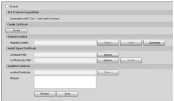
- Enter the required information such as region, IP or domain name, and then click Create.

The entered IP/Domain Name must be the same as the IP or domain name of the Device.
- Click Install under Request Created, and then click Download to download root certificate.
The system pops up Save As dialog box, select storage path, and then click Save.
- Double-click the RootCert.cer icon.
- Click Install Certificate...
Figure 4-75 Install certificate
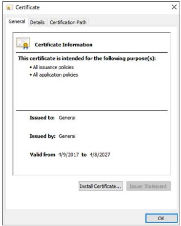
7. Click Next.
Figure 4-76 Certificate store
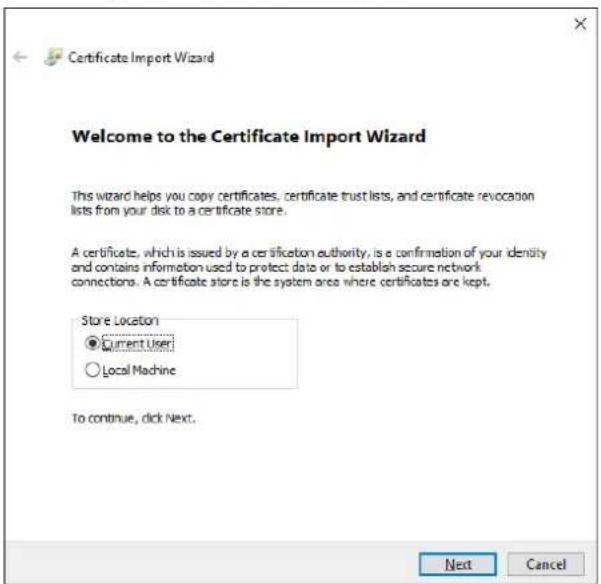
8. Click Next.
Figure 4-77 Complete the certificate import wizard
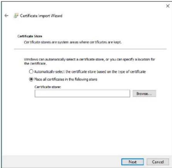
- Click Finish.
- Click Yes, and then click OK on the pop-up window.
• Install Signed Certificate.
- Select Setting > System > Security > HTTPS.
- Select Enable, and Compatible with TLSv1.1 and earlier versions.
- Click Browse to upload the signed certificate, and certificate key, and then click Upload.
- To install the root certificate, see operation steps from 4 to 10 in Create Certificate.
Step 2 Select Enable, and click OK.
The configuration takes effect until the Device restarts.
Step 3 Use HTTPS to log in to the Device.
- Enter https://IP address in the browser.

IP address is the Device IP address or domain name.
- Enter the username, and password to log in to the Device.
4.5.8.3.3 Firewall
Set the security rules to protect the safety of your device system.
Step 1 Select Setting > System > Security > Firewall.
Figure 4-78 Firewall
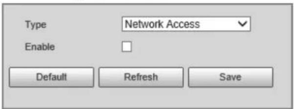
Step 2 Select Type.
- Network Access: Add the IP address to allowlist or blocklist to allow or restrict it from
accessing the corresponding ports of the device.
- PING Prohibited: IP address of your camera is prohibited from ping. This helps to prevent unauthorized attempts at accessing your network system.
- Anti Half Connection: Prevents half-open SYN attacks.
Step 3 Select Enable to enable the rule type that you selected.
Step 4 Click Save.
4.5.8.4 Default
Select Setting > System > Default, and then you can:
- Click Default to restore most configurations of the Camera to default settings (except information such as IP address, account, and log).
- Click Factory Defaults to restore all configurations of the Camera to default settings, including IP address.
Figure 4-79 Default
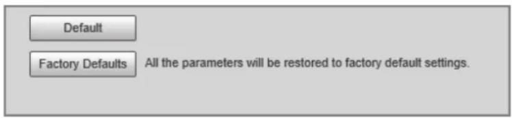
The system supports exporting the configurations from the webpage to local PC, and importing the configuration files from local backup.
Step 1 Select Setting > System > Import/Export.
Figure 4-80 Import/Export
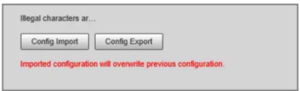
Step 2 Click Config Import or Config Export.
- Config Import: Import the configuration files from local backup.
- Config Export: Export the configuration from the web page to your local computer.

The imported and exported files should be in the format of .backup.
Step 3 Select a path to import files from or export files to.
4.5.8.6 Maintenance Configuration
4.5.8.6.1 Maintenance
Step 1 Select Setting > System > Maintenance > Maintenance.
Figure 4-81 Auto maintain
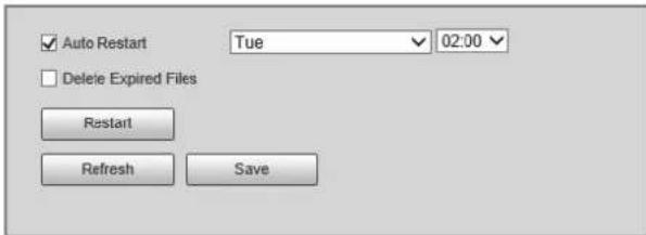
Step 2 Select a restart mode.
- Auto Restart: Select the Auto Restart checkbox, and then configure the day and time. The system will automatically restart at the defined day and time.
- Restart: Click it to manually restart the Device.
Step 3 Select the Delete Expired Files checkbox, and the system will automatically delete the old files.
Step 4 Click Save.
4.5.8.6.2 Emergency Maintenance
Step 1 Select Setting > System > Maintenance > Emergency Maintenance.
Step 2 Select Enable to enable emergency maintenance.
Step 3 Click Save.
4.5.8.7 Update
You need to update the firmware to the latest version to make the Device run properly. Import the update file in the format of .bin to the system, and then update the system.
Step 1 Select Setting > System > Update.
Step 2 Click Browse to select the firmware update file (.bin).
Step 3 Click Update to update the firmware.
Figure 4-82 Update
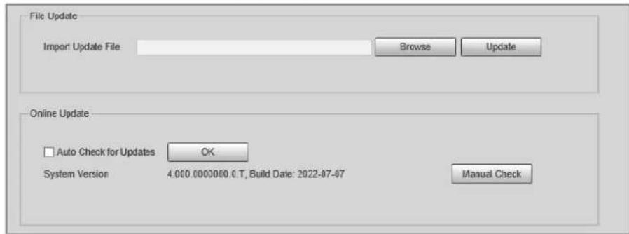
4.5.9 System Information
You can view information such as version, log, online user, and work status.
4.5.9.1 Version Information
- Select Setting > System Info > Version to view information such as device model, and the
version of the hardware, system, and software.
- Select Setting > System Info > Peripheral Version to view version information of the external device, such as flashing light.
4.5.9.2 Log
4.5.9.2.1 System Log
You can search for logs by the time and type, and backup the logs. The log type includes All, System, Setting, Config, Storage, Event, Record Account, and Safety.
Step 1 Select Setting > System Info > Log > Log.
Step 2 Set Start Time and End Time, and then select log type.
Step 3 Click Search.
Step 4 View and backup the search results.
You can save the search results to your computer in a .txt file.
Figure 4-83 Log
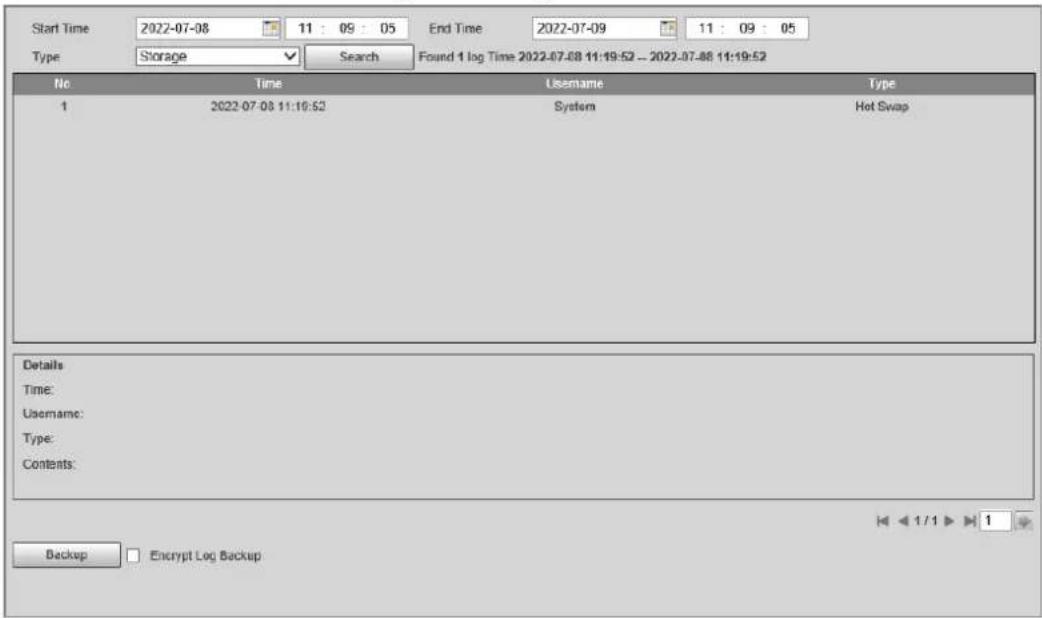
4.5.9.2.2 Remote Log
Critical logs can be saved to the log server. This helps provide important clues to the source of security incidents. The log server needs to be deployed in advance by a professional or system administrator.
Step 1 Select Setting > System Info > Log > Remote Log.
Step 2 Select Enable to enable Remote Log.
Step 3 Configure the IP address, port and device number.
Step 4 Click Save.
Figure 4-84 Remote log
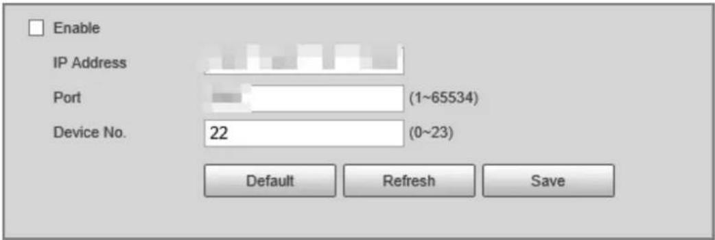
4.5.9.3 Online User
Select Setting > System Info > Online User, and then you can view online users' information, such as username, user local group, IP address, and user login time.
4.5.9.4 Running Status
Select Setting > System Info > Running Status, and then you can view device work status, including CPU, memory and temperature.
4.5.9.5 Legal Information
Select Setting > System Info > Legal Info to view the legal information.
4.6 Alarm
Select Alarm at the upper-right corner of the webpage, and then you can select the event type to trigger an alarm, and also configure the sound of the alarm.

The alarm type might differ depending on the device model.
Figure 4-85 Alarm
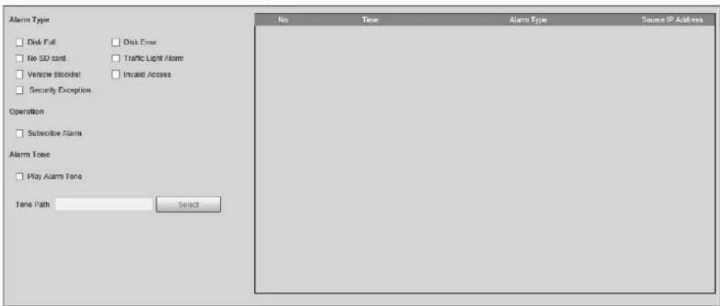
Table 4-42 Alarm parameters
| Name Parameter | Description | |
| Alarm Type | Disk Full | An alarm is triggered when storage is full. |
| Disk Error | An alarm is triggered when storage error occurs. | |
| No SD card | An alarm is triggered when there is no storage space available. | |
| Traffic Light Alarm | An alarm is triggered when a traffic light fails.This function is only available in E Police mode. | |
| Vehicle Blocklist | An alarm is triggered when a license plate in the blocklist is detected. | |
| Invalid Access | An alarm is triggered when illegal access is detected. | |
| Security Exception | An alarm is triggered when a network security problem is detected, such as session hijacking. | |
| Operation Subscribe Alarm | When an alarm is triggered, the Device will inform you on the webpage. | |
| Alarm Tone | Play Alarm Tone | Select the Play Alarm Tone checkbox, and then click Select to select the alarm tone. The system will play the defined alarm tone when an alarm is triggered. |
| Tone Path | ||
Appendix 1 Cybersecurity Recommendations
Cybersecurity is more than just a buzzword: it's something that pertains to every device that is connected to the internet. IP video surveillance is not immune to cyber risks, but taking basic steps toward protecting and strengthening networks and networked appliances will make them less susceptible to attacks. Below are some tips and recommendations from Dahua on how to create a more secured security system.
Mandatory actions to be taken for basic device network security:
1. Use Strong Passwords
Please refer to the following suggestions to set passwords:
- The length should not be less than 8 characters.
- Include at least two types of characters; character types include upper and lower case letters, numbers and symbols.
- Do not contain the account name or the account name in reverse order.
- Do not use continuous characters, such as 123, abc, etc.
- Do not use overlapped characters, such as 111, aaa, etc.
2. Update Firmware and Client Software in Time
- According to the standard procedure in Tech-industry, we recommend to keep your device (such as NVR, DVR, IP camera, etc.) firmware up-to-date to ensure the system is equipped with the latest security patches and fixes. When the device is connected to the public network, it is recommended to enable the "auto-check for updates" function to obtain timely information of firmware updates released by the manufacturer.
- We suggest that you download and use the latest version of client software.
"Nice to have" recommendations to improve your device network security:
1. Physical Protection
We suggest that you perform physical protection to device, especially storage devices. For example, place the device in a special computer room and cabinet, and implement well-done access control permission and key management to prevent unauthorized personnel from carrying out physical contacts such as damaging hardware, unauthorized connection of removable device (such as USB flash disk, serial port), etc.
2. Change Passwords Regularly
We suggest that you change passwords regularly to reduce the risk of being guessed or cracked.
3. Set and Update Passwords Reset Information Timely
The device supports password reset function. Please set up related information for password reset in time, including the end user's mailbox and password protection questions. If the information changes, please modify it in time. When setting password protection questions, it is suggested not to use those that can be easily guessed.
4. Enable Account Lock
The account lock feature is enabled by default, and we recommend you to keep it on to guarantee the account security. If an attacker attempts to log in with the wrong password several times, the corresponding account and the source IP address will be locked.
5. Change Default HTTP and Other Service Ports
We suggest you to change default HTTP and other service ports into any set of numbers between 1024–65535, reducing the risk of outsiders being able to guess which ports you are using.
6. Enable HTTPS
We suggest you to enable HTTPS, so that you visit Web service through a secure communication channel.
7. MAC Address Binding
We recommend you to bind the IP and MAC address of the gateway to the device, thus reducing the risk of ARP spoofing.
8. Assign Accounts and Privileges Reasonably
According to business and management requirements, reasonably add users and assign a minimum set of permissions to them.
9. Disable Unnecessary Services and Choose Secure Modes
If not needed, it is recommended to turn off some services such as SNMP, SMTP, UPnP, etc., to reduce risks.
If necessary, it is highly recommended that you use safe modes, including but not limited to the following services:
- SNMP: Choose SNMP v3, and set up strong encryption passwords and authentication passwords.
- SMTP: Choose TLS to access mailbox server.
- FTP: Choose SFTP, and set up strong passwords.
- AP hotspot: Choose WPA2-PSK encryption mode, and set up strong passwords.
10. Audio and Video Encrypted Transmission
If your audio and video data contents are very important or sensitive, we recommend that you use encrypted transmission function, to reduce the risk of audio and video data being stolen during transmission.
Reminder: encrypted transmission will cause some loss in transmission efficiency.
11. Secure Auditing
- Check online users: we suggest that you check online users regularly to see if the device is logged in without authorization.
- Check device log: By viewing the logs, you can know the IP addresses that were used to log in to your devices and their key operations.
12. Network Log
Due to the limited storage capacity of the device, the stored log is limited. If you need to save the log for a long time, it is recommended that you enable the network log function to ensure that the critical logs are synchronized to the network log server for tracing.
13. Construct a Safe Network Environment
In order to better ensure the safety of device and reduce potential cyber risks, we recommend:
- Disable the port mapping function of the router to avoid direct access to the intranet devices from external network.
- The network should be partitioned and isolated according to the actual network needs. If there are no communication requirements between two sub networks, it is suggested to use VLAN, network GAP and other technologies to partition the network, so as to achieve the network isolation effect.
- Establish the 802.1x access authentication system to reduce the risk of unauthorized access to
private networks.
- Enable IP/MAC address filtering function to limit the range of hosts allowed to access the device.
More information
Please visit Dahua official website security emergency response center for security announcements and the latest security recommendations.
ENABLING A SAFER SOCIETY AND SMARTER LIVING
- Speed Measuring Device
- User's Manual
- Foreword
- General
- Model
- Safety Instructions
- Revision History
- Privacy Protection Notice
- About the Manual
- Important Safeguards and Warnings
- Transportation Requirements
- Storage Requirements
- Installation Requirements
- WARNING
- Operation Requirements
- !
- Maintenance Requirements
- Table of Contents
- Foreword ....
- Important Safeguards and Warnings....III
- Product Information .... 1
- Structure....3
- GUI Operations....7
- Camera....79
- Image....79
- Video....83
- Network Settings 85
- Configuring TCP/IP....85
- Port....87
- Event......89
- Peripheral....90
- Storage....91
- Record....94
- System....96
- Account Management....98
- Product Information
- Introduction
- Main Functions
- Storage
- Radar Visualization
- Radar Calibration
- GUI Operations
- Structure
- Appearance
- Dimensions
- Panels
- Left Panel
- Right Panel
- Front Panel
- GUI Operations
- Introduction
- Login
- Main Interface
- Live Snapshot
- Live
- Snapshot
- Image Manager
- Search
- Backup
- Config
- E-police
- AI Settings
- Scene Config
- Recognition
- Radar Settings
- Parameters
- Radar Visualization
- Radar Calibration
- Camera
- Shutter
- Flashing Light Config
- OSD Settings
- OSD Road Section
- OSD Setting
- OSD Option
- Blocklist/Allowlist
- Allowlist
- Blocklist
- Network Settings
- Network Settings
- Auto Register
- 3G/4G Settings
- Time
- NTP Setting
- Positioning System Time Setting
- Storage Settings
- FTP Upload
- Record
- System Settings
- General Settings
- Auto Maintain
- Safety Settings
- Manage Info
- System Info
- Log Search
- User Manager
- Traffic Flow Statistics
- Webpage Operations
- Introduction
- Initialization
- Webpage Functions
- Live
- Video Stream
- Live View
- Plate Number Recognition
- Plate Snapshot
- Functions on the Live Page
- Vehicle Snapshot
- Event List
- Radar
- Radar Settings
- Calibrating the Radar
- Configuring General Information
- Radar Visualization
- Search
- Searching for Vehicles
- Step 4 Select the download type, and then click Download.
- Searching for Recorded Videos
- Setting
- ITC
- Smart Plan
- ANPR Snapshot
- Configuring Violation Snapshot
- Lane Parameters
- Lane Properties
- Rule Configuration
- Vehicle Detection
- Other Configuration
- Configuring Intelligent Analysis
- Recognition
- Advanced
- Default
- Configuring Original Picture OSD
- Configuring Combination Picture OSD
- Configuring Cutout
- E Police
- Configuring Violation Snapshot
- Configuring Intelligent Analysis
- Traffic Light Configuration
- Lens Flare Reduction
- Configuring Original Picture OSD
- Configuring Combination Picture OSD
- Configuring Cutout
- Composition & OSD
- Configuring Picture Synthesis
- Configuring Video OSD
- Transfer Offline
- Vehicle Allowlist/Blocklist
- Setting Allowlist
- Setting Blocklist
- Traffic Flow
- Watermark
- Verifying Images
- Verifying Videos
- Camera
- Image
- Configuring General Parameters
- Configuring Shutter
- Configuring Metering Zone
- Video
- Configuring Video Parameters
- Configuring ROI
- Network Settings
- Configuring TCP/IP
- Port
- Configuring Port
- Configuring ONVIF
- Configuring Auto Registration
- Configuring 802.1x
- Event
- Exception
- Device Location
- Peripheral
- Device Status
- External Light
- Storage
- Storage Spot Config
- Local Storage
- FTP
- Storage Path
- SMART
- Record
- Record Control
- Schedule
- System
- General
- General Settings
- Date & Time
- Account Management
- Account
- Related Operations
- ONVIF User
- Procedure
- Security
- System Service
- HTTPS
- Prerequisites
- Click Next.
- Click Next.
- Firewall
- Default
- Maintenance Configuration
- Maintenance
- Emergency Maintenance
- Update
- System Information
- Version Information
- Log
- System Log
- Remote Log
- Online User
- Running Status
- Legal Information
- Alarm
- Appendix 1 Cybersecurity Recommendations
- Use Strong Passwords
- Update Firmware and Client Software in Time
- Physical Protection
- Change Passwords Regularly
- Set and Update Passwords Reset Information Timely
- Enable Account Lock
- Change Default HTTP and Other Service Ports
- Enable HTTPS
- MAC Address Binding
- Assign Accounts and Privileges Reasonably
- Disable Unnecessary Services and Choose Secure Modes
- Audio and Video Encrypted Transmission
- Secure Auditing
- Network Log
- Construct a Safe Network Environment
- More information
Brand : Dahua Technology
Model : HWS1600D
Category : Measurement