
B-31 - Security Camera Advidia - Free user manual and instructions
Find the device manual for free B-31 Advidia in PDF.


| Product Type | Security Camera |
| Brand | Advidia |
| Model | B-31 |
| Video Resolution | 1920 x 1080 (Full HD) |
| Frame Rate | 30 fps |
| Lens Type | Fixed focal, 2.8 mm |
| Field of View | 106° (horizontal) |
| Night Vision | IR LEDs, up to 30 meters |
| Day/Night Mode | Auto IR cut filter |
| Compression | H.265, H.264, MJPEG |
| Audio | Built-in microphone, 1-way audio |
| Network Interface | 10/100 Ethernet (PoE) |
| Power Supply | PoE (IEEE 802.3af) or 12V DC |
| Power Consumption | ≤ 5W |
| Dimensions (W x H x D) | 70 x 70 x 150 mm |
| Weight | 350 g |
| Ingress Protection | IP67 (weatherproof) |
| Operating Temperature | -30°C to 60°C |
| Storage | MicroSD slot (up to 128 GB) |
| Mounting | Wall or ceiling bracket included |
| Features | Motion detection, ONVIF compatible |
| Cleaning | Wipe with soft dry cloth; avoid solvents |
| Security | Password protection, HTTPS, firmware updates |
| Repairability | Moderate; spare parts available through distributor |
Frequently Asked Questions - B-31 Advidia
User questions about B-31 Advidia
0 question about this device. Answer the ones you know or ask your own.
Ask a new question about this device
Download the instructions for your Security Camera in PDF format for free! Find your manual B-31 - Advidia and take your electronic device back in hand. On this page are published all the documents necessary for the use of your device. B-31 by Advidia.
USER MANUAL B-31 Advidia
3.6x Zoom H.264 4-Megapixel IP D/N Vandal-Proof PoE Rugged Dome with P-Iris & ExDR

natural_image
Close-up of a white security camera with 'advidia' branding on the dome (no additional text or symbols visible)Table of Contents
1. Precautions 3
2. Introduction 4
Package Contents......4
Features and Benefits .... 5
Safety Instructions 7
Physical description....9
Product Specification 12
3. Installation Procedure 14
Connecting the IP Outdoor Rugged Dome 14
1) Remove the cover.... 14
2) Insert the cable 14
3) Connect cables to connectors....14
How to Do the Waterproof Installation....15
4. Accessing Camera 18
If you have DHCP server / router in your network .... 18
If you do NOT have DHCP server / router in your network:...... 18
1. Precautions
Read these instructions
You should read all the safety and operating instructions before using this product.
Heed all warnings
You must adhere to all the warnings on the product and in the instruction manual. Failure to follow the safety instruction given may directly endanger people, cause damage to the system or to other equipment.
Servicing
Do not attempt to service this video device yourself as opening or removing covers may expose you to dangerous voltage or other hazards. Refer all servicing to qualified service personnel.
Trademarks
All names used in this manual are probably registered trademarks of respective companies.
Liability
Every reasonable care has been taken during the writing of this manual. Please inform your local office if you find any inaccuracies or omissions. We cannot be held responsible for any typographical or technical errors and reserve the right to make changes to the product and manuals without prior notice.
FCC/CE Regulation
NOTE: This equipment has been tested and found to comply with the limits for a Class A digital device, pursuant to Part 15 of the FCC Rules. These limits are designed to provide reasonable protection against harmful interference when the equipment is operated in a commercial environment. This equipment generates, uses, and can radiate radio frequency energy and, if not installed and used in accordance with the instruction manual, may cause harmful interference to radio communications. Operation of this equipment in a residential area is likely to cause harmful interference in which case the users will be required to correct the interference at their own expense.
2. Introduction
Package Contents
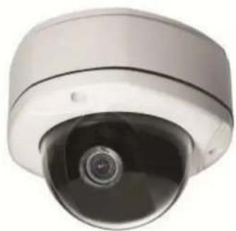
3.6x Zoom H.264 4-Megapixel IP D/N
Vandal Proof PoE Rugged Dome QIG
natural_image
Close-up of a white surveillance camera with a circular lens (no visible text or symbols)
Product CD Terminal Blocks for Power DI/O and Audio

natural_image
Circular optical disc with a central metallic ring, no text or symbols visibleAccessories

Drill Template

natural_image
Close-up of three black screw fasteners and two white plastic components with flanges (no text or symbols visible)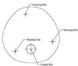
Drill template(scale 1:1)
Features and Benefits
This is a cutting edge network video surveillance camera. It can capture, compress and transmit real time video in excellent quality (8 FPS 4Megapixel, 2032 x 1920). This camera is your best choice to build an intelligent IP surveillance system.
Adaptive Profile
With the innovative embedded Image Signal Processor (ISP), this camera responds to changing lighting condition with customized algorithm. This allows for clear image with very little noise at night.
H.264/MPEG-4/MJPEG Triple Codec Dual Streaming
This device supports 3 compression formats, H.264, MPEG-4 and MJPEG. It brings superior image quality at 8 frames per second up to resolution of 2032 x 1920 pixels, and offers up to 15 frames per second in Full HD 1080p (!920 x 1080). In 720p (1280 x 720) and VGA resolution (640 x 480) the device reaches 30 frames per second.
Rugged Vandal-Proof Construction withstands all kinds of abuse.
Special engineer polymer clear dome shell protects against brute force impact. It is extremely durable against any tampering intruder. IP66 construction isolates electronics against the elements. Rain, sleet or snow, nothing goes through. Temperature control ensures cold-start capability for use in the worst of weathers.
ExDR (Extreme Dynamic Range)
Extreme Dynamic Range technology is the most advanced approach of improving the dynamic range of the camera. While many other WDR technologies enhance the dynamic range while producing noise, blur edges of objects and untrue colors, ExDR is designed to improve the dynamic range while keeping the true colors, sharp edges of objects and free from noise.
P Iris Control
With optional P Iris Lens, this camera automatically adjusts incoming light levels to achieve the best video performance. Wildly fluctuating outdoor lighting condition is no longer an issue with your video quality.
Powerful Bundled Surveillance Software
To extend the capabilities of the IP Dome Camera series, a powerful surveillance program is included in the package for free. Users can easily use an existing PC as a digital video recorder. Scheduled recording and manual recording keep every important video recorded in the local hard disk. Reliable and accurate motion detection with instant warning enables immediate response in every condition. Quick and simple search and playback function lets you easily find the images and video you want.
Safety Instructions
Don't use the power supply with other voltages
This device is likely to be damaged or damage other equipment / personnel, if you use a power supply with different voltage than the one included with this device. All warranty of this product will be voided in the situations above.
Don't open the housing of the product
Cleaning
Disconnect this video product from the power supply before cleaning.
Attachments
Do not use attachments not recommended by the video product manufacturer as they may cause hazards.
Water and Moisture
Do not use this video product near water, for example, near a bathtub, washbowl, kitchen sink, or laundry tub, in a wet basement, or near a swimming pool and the like.
Don't use accessories not recommended by the manufacturer
Only install this device and the power supply in a dry place protected from weather
Servicing
Do not attempt to service this video product yourself as opening or removing covers may expose you to dangerous voltage or other hazards. Refer all servicing to qualified service personnel.
Damage Requiring service
Disconnect this video product from the power supply immediately and refer servicing to qualified service personnel under the following conditions.
1) When the power-supply cord or plug is damaged
2) If liquid has been spilled, or objects have fallen into the video product.
3) If the video product has been directly exposed to rain or water.
4) If the video product does not operate normally by following the operating Instructions in
this manual. Adjust only those controls that are covered by the instruction manual, as an improper adjustment of other controls may result in damage, and will often require extensive work by a qualified technician to restore the video product to its normal operation.
Safety Check
Upon completion of any service or repairs to this video product, ask the service technician to perform safety checks to determine if the video product is in proper operating condition.
Physical Description
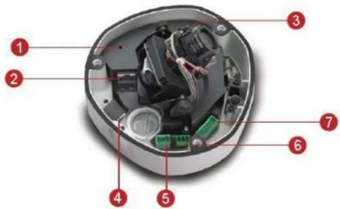
1 Power Button
2 Ethernet Port
3 Reset Button
4 MicroSD / MicroSDHC Card Slot
5 Audio Input / Output
6 DC 12V Power Input
7 Digital Input / Output
1) Power Button
Press the Power Button and then camera will reboot automatically.
2) Ethernet Port
The IP device connects to the Ethernet via a standard RJ45 connector. Supporting NWAY, this IP device can auto detect the speed of local network segment (10Base-T/100Base-TX Ethernet).
3) Reset Button
Step 1: Switch off IP device by disconnecting the power cable
Step 2: Press and continue to hold the Reset Button (with a sharp tipped object, like a pen.)
Step 3: Reconnect the power cable while continuing to hold the reset button. The red Power LED light will flash on for 3 second first, turn off for about 15 seconds, flash on for another second and turn off again. By this time the reset to default operation is already completed. This will take around 20 seconds from power up. You may then release the reset button. This length of time fluctuates slightly with the environment. The Power LED light will come back on and stay on after a few more seconds. The unit will start up with factory default settings automatically.

flowchart
graph LR
    A["Power On"] --> B["On (3s)"]
    B --> C["Off (about 15s)"]
    C --> D["On 1s"]
    D --> E["Off (10~15s)"]
    E --> F["Stay On"]
    G["Restore to Default Complete"] --> D
    H["About 20 Seconds"] --> I["Yellow Line"]
4) Micro SD / Micro SDHC Card Slot\*
Insert your Micro SD card here for local recording on camera
5) Audio Input / Output
The IP device supports audio input and output via terminal block
6) DC 12V Power Input
Connect DC power source to the terminal block. The wire with white dashed lines is the live wire, which should connect to the 12V pin.

| PIN | NAME | DESCRIPTION |
| 1 | N | AC Power Input |
| 2 | L | |
| 3 | GND | E-Ground of power |
7) Digital Input / Output
Used in applications like motion detection, event triggering, time lapse recording, alarm notifications, etc., the I/O terminal connector provides the interface to:
- 2 transistor output - For connecting external devices such as relays and LEDs.
Connected devices can be activated by Output buttons on the Live View page or through video management software. Connect Pin 2 with 4 or 6 with 8. - 2 Digital Input - An alarm input for connecting devices that can toggle between an open and closed circuit, for example: PIRs, door/window contacts, glass break detectors, etc. The device will detect the change in digital input and transmit the signal to video surveillance servers.
| Pin 1 | GND | Ground. Connect with Pin 3 for DI control loop. | |
| Pin 2 | 12V | Provides power to external devices with a maximum current of 100mA. | Voltage: 12V DC, Max: 1.2W |
| Pin 3 | Digital Input | Connect to GND to activate, or leave floating (or unconnected) to deactivate. | Must not be exposed to voltages greater than 30V DC. |
| Pin 4 | Transistor Output | Connect to Pin 2 through external devices for DO loop. If used with an external relay, a diode must be connected in parallel with the load for protection against transient voltages. | Max load = <100mA Max voltage = 24V DC (to the transistor) |
(Pin 5 – 8 repeats Pin 1-4 for another set of DIO)
Connect input/output devices to the camera as follows:
- Attach the cables for the device securely to the supplied green connector block.
- Once cables are connected, push connector block into the terminal connector on camera.
Product Specification
| 3.6x Zoom H.264 4-Megapixel IP D/N Vandal Proof PoE Rugged Dome with P-Iris, ExDR | |
| • Device | |
| Device Type | Fixed Dome Camera |
| Image Sensor | Aptina Progressive Scan CMOS |
| Sensor Size | 1/3.2" (4.5 x 3.4 mm) |
| Horizontal Resolution | 1422 TVL |
| Day / Night | Yes |
| Minimum Illumination | Color: 0.1 lux at F1.4 (30 IRE, 2400°K); B/W: 0.05 lux at F1.4 (30 IRE, 2400°K) |
| Color to B/W switch | ISP based switch, configurable |
| Mechanical IR Cut Filter | Yes |
| IR Sensitivity Range | No |
| IR LED | No |
| Electronic Shutter | 1/25 - 1/2000 sec (50Hz); 1/15 - 1/2000 sec (60Hz) (manual mode)1 - 1/2000 sec (auto mode) |
| • Lens | |
| Focal Length | Zoom, f3.3 - 12 mm / F1.4 - F2.9 |
| Zoom Ratio | 3.6x optical |
| Iris | P-Iris |
| Focus | Auto Focus |
| Mount Type | Board Mount |
| Horizontal Viewing Angle | 77.22° - 22.62° |
| Viewing Angle Adjustment | Pan:0° - 360°; Tilt: 0° - 180°; Rotate: 0° - 360° |
| • Video | |
| Compression | H.264, MPEG-4 SP, MJPEG |
| Maximum Frame Rate vs. Resolution (H.264, MJPEG) | 8 fps at 2032 X 1920; 15 fps at 1920 X 1080 (HD 1080p); 30 fps at 1280 x 720 (HD 720p); 30 fps at 640 x 480 (VGA) |
| Maximum Frame Rate vs. Resolution (MPEG-4 SP) | 5 fps at 2032 X 1920; 11 fps at 1920 X 1080 (HD 1080p); 25 fps at 1280 x 720 (HD 720p); 30 fps at 640 x 480 (VGA) |
| 4 Cropped VGA Mode (All Compressions) | 15 fps at 640 x 480 (VGA) |
| Multi-Streaming | Simultaneous dual steams based on two configurations in single view mode;Multiple streams based on single configuration in 4 cropped VGA mode |
| Bit Rate | 28 Kbps - 6 Mbps (per stream) |
| Bit Rate Mode | Constant, Variable |
| Image Enhancement | ExDR (Extreme Dynamic Range); White balance: automatic, hold and manual; Brightness; Saturation; Contrast;Sharpness; Automatic gain control; 2D+ 3D Digital noise reduction; Flickerless; Defogging |
| Privacy Mask | 4 configurable regions |
| Text Overlay | User defined text on video |
| Image Orientation | Image flip and mirror |
| • Audio | |
| Compression | 8 kHz, Mono, PCM, 16 bit encoding |
| Audio-In | Terminal block |
| Audio-Out | Terminal block |
| • Network | |
| Protocol & Service | TCP, UDP, HTTP, HTTPS, DHCP, PPPoE, RTP, RTSP, IPv6, DNS, DDNS, NTP, ICMP, ARP, IGMP, SMTP, FTP, UPnP, SNMP, Bonjour |
| Ethernet Port | 1, Ethernet (10/100 Base-T), RJ-45 connector |
| Security | IP address filtering; HTTPS encryption; Password protected user levels; IEEE 802.1X network access control |
| • Alarm | |
| Alarm Trigger | Video motion detection 3 regions in single view mode,1 region each in 4 cropped VGA mode; External device through digital input |
| Alarm Response | Notify control center; Go to Zoom preset point or preset tour; Change camera settings; Command other devices; E-mail notification with snapshots; Save video or snapshot to local storage; Upload video, snapshot to FTP server; Activate external device through digital output |
| • Interface | |
| Digital Input | 2, terminal block |
| Digital Output | 2, terminal block |
| Local Storage | MicroSD/SDHC memory card slot (card not included) |
| • General | |
| Power Source / Consumption | PoE Class 3 (IEEE802.3af) / 12.24W (IR on)DC 12V /10.2W (IR on) (adapter not included) |
| Weight | 1200 g (2.65 lb) |
| Dimensions (Φ x H) | 151.69 mm x 114.9 mm (5.97" x 4.52") |
| Environmental Casing | Weatherproof (IP66 rated); Transparent vandal proof dome cover, up to 659.23 kgF (1453.35 lbF) |
| Mount Type | Surface, Pendant, Wall, Corner, Pole, Flush |
| Operating Temperature | -30°C ~ 50°C (-22°F ~ 122°F) |
| Operating Humidity | 10% ~ 85% RH |
| Approvals | Camera: CE, FCC, IP66 |
2. Installation Procedure
Connecting the IP Outdoor Rugged Dome
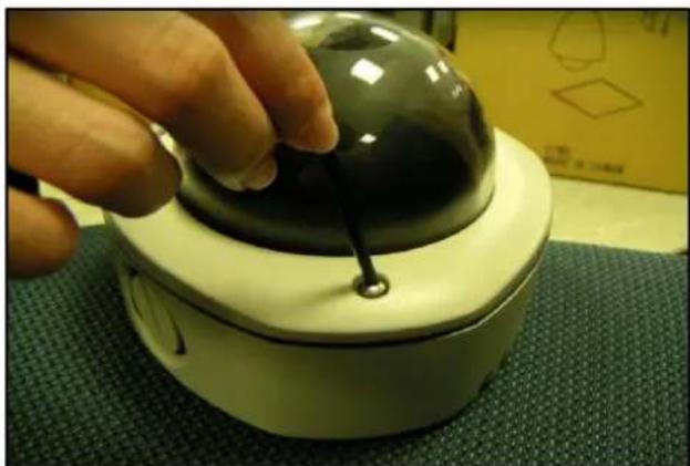
1) Remove the cover
Remove the dome cover with special hex wrench in the accessory kit.
natural_image
Close-up of a hand adjusting a black dome-shaped object with a string, placed on a green textured surface (no visible text or symbols)2) Insert the cable
There are two conduit holes on this rugged dome. One is at the bottom, while the other is at the side and covered with a plug. Remove the plug if your cable will go through the one at the side of the rugged dome

natural_image
Close-up of a device's internal components being inserted into a circular housing, showing circuit board and wiring (no text or symbols visible)3) Connect cables to connectors
Please follow the instructions in the Physical Description section for how to connect to each connector.
How to Do the Waterproof Installation
The following installation procedure makes the camera be water-resistant even for the situations where the camera can easily be flooded by pouring rain.
The important part to focus on during the installation:
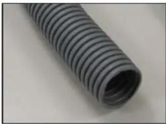
The protection of the cabling has to be done by a proper flex conduit. The size of the flex conduit that matches with the conduit gland is 3/4" (trade size), or with actual physical diameter of 26.441mm.
natural_image
Close-up of a coiled black plastic tube with parallel grooves (no text or symbols visible)Have the Ethernet cable inserted through the flex conduit together with RJ-45 connector. You may also consider to do the RJ-45 connector crimping after pushing the cable through the conduit.
natural_image
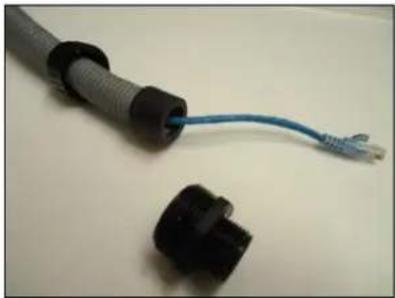
Close-up of three black plastic connectors with a blue cable attached, no visible text or symbolsSlide the clamping nut around flex conduit some 10-20 cm away from the top. Fit the sealing insert (made of rubber) to the top of the flex conduit.
natural_image
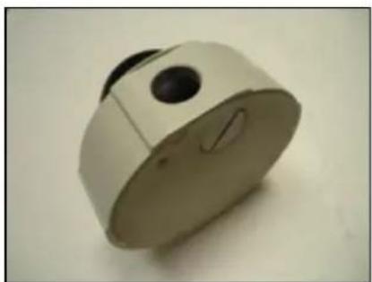
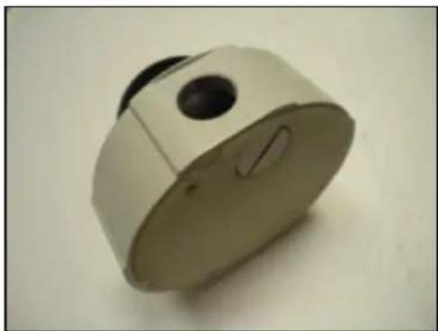
Two black plastic connectors with blue wires attached, one with a mesh cap and the other with a coiled cable (no text or symbols visible)On the camera side, decide which of the 2 possible holes you are going to use to connect the flex conduit. There is one hole on the side, and one on the bottom. Whichever you pick, remember to seal off the other one with the metal patch (included in the camera set).
natural_image
White cylindrical mechanical component with a black circular end and a small notch, resting on a plain surface (no text or symbols visible)
natural_image
Close-up of a white mechanical knob or dial with a curved knob and central button (no text or symbols visible)Scenario 1 – using the side hole.
natural_image
Close-up of a white cylindrical mechanical component with a black circular hole and a small slot, resting on a plain surface (no text or symbols visible)Scenario 2 – using the bottom hole.
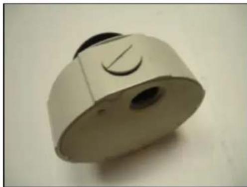
natural_image
Close-up of a white mechanical component with a circular button and central slot (no text or symbols visible)Screw the body of the conduit gland into the camera and fix it with the lock nut (included in the set of conduit gland that you purchased) from the inside of the camera..

natural_image
Close-up of a black spherical device with attached wires and connectors, next to a metallic housing (no text or symbols visible)
natural_image
Close-up of a handheld electronic device with black connectors and a blue cable, no visible text or symbols.Connect the Ethernet cable to the camera's network port. If you are not using PoE, then please remember to pull the DC power cable through the flex conduit as well, and connect to the camera at this point.

natural_image
Close-up of a black spherical device with exposed internal components connected to a blue cable (no text or symbols visible)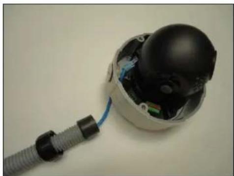
natural_image
Close-up of a black spherical device with exposed internal components connected to a blue cable (no text or symbols visible)Push the head of the flex conduit, wrapped with sealing insert, into the body of the conduit gland.

natural_image
Close-up of a black plastic electronic device with exposed internal components and coiled cable (no text or symbols visible)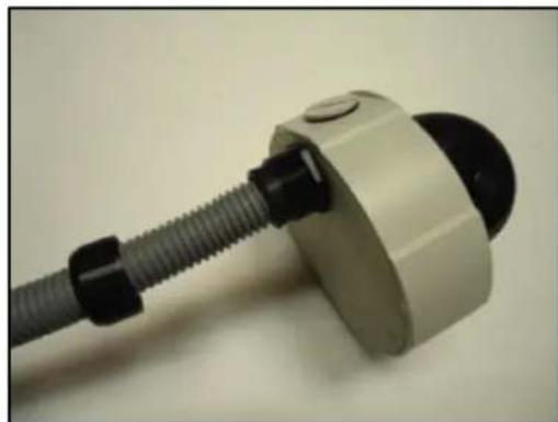
natural_image
Close-up of a mechanical component with threaded connectors and a circular housing (no visible text or symbols)Screw the clamping nut tightly onto the body of the conduit gland.
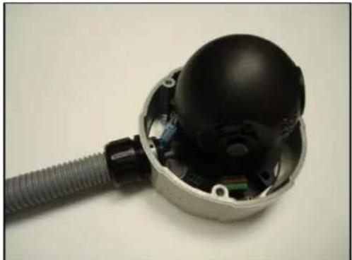
natural_image
Interior view of a mechanical device with exposed internal components and a coiled cable (no text or symbols visible)
natural_image
Close-up of a mechanical component with a black threaded end and a circular dial (no visible text or symbols)Adjust the viewing angle and focus of the camera and put the dome cover back on, and tighten it by using the screws.

natural_image
Close-up of a white spherical sensor or camera with a black dome and coiled cable, isolated on plain background (no text or symbols visible)
natural_image
Close-up of a white and black spherical object with a coiled cable, possibly a surveillance camera or sensor device (no visible text or symbols)You have completed a fully waterproof installation!
3. Accessing Camera
If you have DHCP server / router in your network:
Many network server / routers are able to automatically provide IP addresses through DHCP. If you are using such a network, just plug in your computer and IP Dome Cam into the network and your IP device will acquire network address by itself.
If you do NOT have DHCP server / router in your network:
- Configure your PC to use the same subnet by changing your PC's IP address to the subnet with prefix 192.168.0.XXX. The last number should be anything from 1 to 254 except 100 and other occupied IP addresses. Subnet mask should be 255.555.255.0.
- The default IP used by this device is 192.168.0.100. Please make sure your PC is NOT using this address and that no two devices use the same IP address in the network.
- Change your IP address by going to Control Panel ->Manage Network Connections -> Right click on the connection to change -> Option -> TCP/IP IPv4 Properties.

Please set the settings as below.
●
IP address: 192.168.0.xxx
- Subnet mask: 255.255.255.
0
(NOTE: xxx should be a number from 1 to 254 except 100, which is used by the IP device. Please also make sure that no two equipments use the same IP address in the
- Open Internet Explorer (Version 6.0 or above), and type in the Default IP: 192.168.0.100
- When you see the login window, please input default user and password: Default User: Admin Password: 123456

- After logging in, you will see the video from camera. To go to the main menu, click the "Setup" button on the top left.

If you are using a single camera, this is enough to access the device.
If you are using multiple devices, you need to change the current device to another unused IP address, so that when the next device is connected to the network, no two devices use the same IP. Please perform the following steps.
- Go to Network -> Connection Type
- Change the IP mode to Static.
- Change the IP to 192.168.0.101 or any other unused IPs. Do NOT use the PC's IP address or 192.168.0.100.). If this is not the first device you add to the network, please also avoid other devices' IPs.

- Click "Apply"
- Please go to System -> Save & Reboot, and click "Apply". Internet Explorer will close after a few seconds. This is normal.
- Wait for 30 seconds, and open IE again to connect to the new IP. (In this example, 192.168.0.101). For the second device or more you add into the network, please type the correct IP.
- Adjust the default Video setting by going to "Video & Audio".
- Table of Contents
- Precautions 3
- Introduction 4
- Installation Procedure 14
- Accessing Camera 18
- Precautions
- Read these instructions
- Heed all warnings
- Servicing
- Trademarks
- Liability
- FCC/CE Regulation
- Introduction
- Package Contents
- Features and Benefits
- Adaptive Profile
- H.264/MPEG-4/MJPEG Triple Codec Dual Streaming
- Rugged Vandal-Proof Construction withstands all kinds of abuse.
- ExDR (Extreme Dynamic Range)
- P Iris Control
- Powerful Bundled Surveillance Software
- Safety Instructions
- Don't use the power supply with other voltages
- Don't open the housing of the product
- Cleaning
- Attachments
- Water and Moisture
- Don't use accessories not recommended by the manufacturer
- Damage Requiring service
- Safety Check
- Physical Description
- 1) Power Button
- 2) Ethernet Port
- 3) Reset Button
- 4) Micro SD / Micro SDHC Card Slot\*
- 5) Audio Input / Output
- 6) DC 12V Power Input
- 7) Digital Input / Output
- (Pin 5 – 8 repeats Pin 1-4 for another set of DIO)
- Product Specification
- Installation Procedure
- Connecting the IP Outdoor Rugged Dome
- 1) Remove the cover
- 2) Insert the cable
- 3) Connect cables to connectors
- How to Do the Waterproof Installation
- The important part to focus on during the installation:
- Accessing Camera
- If you have DHCP server / router in your network:
- If you do NOT have DHCP server / router in your network:
Brand : Advidia
Model : B-31
Category : Security Camera