
AKEV160 - Fan Air King - Free user manual and instructions
Find the device manual for free AKEV160 Air King in PDF.


| Product Type | Exhaust Recovery Ventilator (ERV) / Heat Recovery Ventilator (HRV) |
| Model | AKEV160 by Air King |
| Power Supply | 120 VAC, 60 Hz, grounded 3-prong plug |
| Control Voltage | 24 VAC for wall control and furnace interlock |
| Installation | Ceiling mounted with anti-vibration straps; indoor use only; not for attic or unconditioned space |
| Duct Connection | 6-inch round duct collars (supply and exhaust) |
| Airflow Capacity | Balanced to within 10% between supply and exhaust; adjustable via speed control |
| Operation Modes | Off, Standby, Low Speed, High Speed, 20/40 Cycle, Recirculation, Timer |
| Humidity Control | Built-in dehumidistat with adjustable setpoint (20–80% RH); triggers high speed above setpoint |
| Filters | Polyester washable filters (standard); optional MERV filters; clean every 3 months, replace every 1–3 years |
| Maintenance Indicator | Wrench icon and yellow LED after 3 months; reset by holding power button 5 seconds |
| Condensate Drain (HRV Only) | Includes drain hose assembly with P-trap; pour water to form air seal |
| Safety Features | Disconnect power before servicing; do not use with solid-state speed control; do not install in kitchens |
| Warranty | 1 year limited warranty from date of original purchase; covers defects in workmanship/materials |
| Included Accessories | RVC8 wall control, anti-vibration straps, terminal blocks, drain hose (HRV), core, filters |
| Replacement Parts | Motors, capacitors, circuit board, core, filters, wall control available (see manual for part numbers) |
Frequently Asked Questions - AKEV160 Air King
User questions about AKEV160 Air King
0 question about this device. Answer the ones you know or ask your own.
Ask a new question about this device
Download the instructions for your Fan in PDF format for free! Find your manual AKEV160 - Air King and take your electronic device back in hand. On this page are published all the documents necessary for the use of your device. AKEV160 by Air King.
USER MANUAL AKEV160 Air King
IMPORTANT INSTRUCTIONS - OPERATING MANUAL
AKEV, AKHV Series

Exhaust Recovery Ventilator
Heat Recovery Ventilator

READ AND SAVE THESE INSTRUCTIONS
READ CAREFULLY BEFORE ATTEMPTING TO ASSEMBLE, INSTALL, OPERATE OR MAINTAIN THE PRODUCT DESCRIBED. PROTECT YOURSELF AND OTHERS BY OBSERVING ALL SAFETY INFORMATION. FAILURE TO COMPLY WITH INSTRUCTIONS COULD RESULT IN PERSONAL INJURY AND/OR PROPERTY DAMAGE!

RETAIN INSTRUCTIONS FOR FUTURE REFERENCE.
GENERAL SAFETY INFORMATION

When using electrical appliances, basic precautions should always be followed to reduce the risk of fire, electric shock and injury to person, including the following:


WARNING: TO REDUCE THE RISK OF FIRE, ELECTRIC SHOCK AND INJURY TO PERSON, OBSERVE THE FOLLOWING:
a) Use this unit only in the manner intended by the manufacturer. If you have questions, contact the manufacturer.
b) Before servicing or cleaning the unit, disconnect the power cord from the electrical outlet.
c) ONLY qualified persons should attempt repair or service of any electrical/internal component of this product.

WARNING: TO REDUCE THE RISK OF FIRE, REMOVE ANY SHIPPING MATERIAL THAT MAY BE PRESENT INSIDE THE UNIT.
c) The cover to this unit is removable to ensure ease of access to internal components during cleaning and servicing. USE CAUTION when opening or removing the cover of the unit to avoid risk of personal injury or damage to the cover.
d) Installation work and electrical wiring must be done by qualified person(s) in accordance with all applicable codes and standards, including fire-related construction.
e) Sufficient air is needed for proper combustion and exhausting of gases through the flue (chimney) of fuel burning equipment to prevent back drafting. Follow the heating equipment manufacturer's guideline and safety standards such as those published by the National Fire Protection Association (NFPA) and the American Society for Heating, Refrigeration, and Air Conditioning Engineers (ASHRAE), and the local code authorities.
f) When cutting or drilling into wall or ceiling, do not damage electrical wiring and other hidden utilities.


CAUTION: FOR GENERAL VENTILATING USE ONLY. DO NOT USE TO EXHAUST HAZARDOUS OR EXPLOSIVE MATERIALS AND VAPORS.
g) Ducted fans must always be vented to the outdoors. Do not intake/exhaust into or from between walls, ceilings, attics, crawl spaces or garages.
h) Do not run any air ducts directly above or closer than 2 ft to any furnace or its supply plenum, boiler, or other heat producing appliance. If a duct has to be connected to the furnace return plenum, it must be connected not closer than 9' 10" from this plenum connection to the furnace (applies only in regions where the outside temperature falls below 32°F).
i) This unit must be grounded. The power cord is equipped with a three-prong grounded plug that must be inserted into a matching receptacle. Under no circumstances should the ground prong be cut off the plug. Where a two-prong wall receptacle is encountered, it must be replaced with a properly grounded three-prong receptacle installed in accordance with the National Electrical Code (NEC) and all applicable local codes and ordinances. This work must be done by a qualified electrician, using copper wires only.
j) To avoid motor bearing damage and noisy and/or unbalanced impellers, keep drywall spray, construction dust, etc. off power unit. Turn unit OFF during construction or renovations.
k) Read all instructions before installing or using exhaust fan.
I) For residential installations only.
m) Must use suitable weather hood with insect screen to protect air intake.
n) DO NOT install this product in an unconditioned space—61° F ambient temperature is recommended—or in a space/manner where maintenance and service might pose a risk of personal injury or damage to this product.
o) If ductwork passes through unconditioned spaces, it must be insulated.


WARNING: TO REDUCE THE RISK OF FIRE, ELECTRIC SHOCK, DO NOT USE THIS FAN WITH ANY SOLID-STATE SPEED CONTROL DEVICE.
p) This unit is not designed to provide combustion and/or dilution air for fuel-burning appliances.
q) Due to the weight of the unit, two installers are recommended to perform installation.


WARNING: DO NOT USE IN KITCHENS.

WARNING: FOR INDOOR INSTALLATIONS ONLY.

WARNING: THE DUCTING FROM THIS FAN TO THE OUTSIDE OF THE BUILDING HAS A STRONG EFFECT ON THE AIR FLOW, NOISE AND ENERGY USE OF THE THE SHORTEST, STRAIGHTEST DUCT ROUTING POSSIBLE FOR BEST PERFORMANCE, DID INSTALLING THE FAN WITH SMALLER DUCTS THAN RECOMMENDED. INSULATION TO THE DUCTS CAN REDUCE ENERGY LOSS AND INHIBIT MOLD GROWTH. FANS LED WITH EXISTING DUCTS MAY NOT ACHIEVE THEIR RATED AIRFLOW.
INSTALLATION CONSIDERATIONS:
Prior to integrating this ERV/HRV with any other piece of mechanical equipment, i.e. furnace, air handler, combustion heating appliance, careful consideration must be given to system design and integration to ensure compatibility and proper operation of both appliances. Do not connect the duct system of your ERV/HRV to any clothes dryer or kitchen exhaust fan duct system.
Whether installing this ERV/HRV as part of an independent system or to integrate it with a central heating/cooling system, use the procedure in this manual to ensure that the air flows of the ERV/HRV are balanced. Only a properly balanced ERV/HRV will deliver maximum performance and energy efficiency.
Although this document contains guidelines for proper ERV/HRV sizing and installation, your ventilation system should be installed in conformance to the appropriate local or state building regulations or National Building Code and/or ASHRAE "Good Engineering Practices".
SAVE THESE INSTRUCTIONS
INSTALLATION INSTRUCTIONS

CAUTION: MAKE SURE UNIT IS UNPLUGGED BEFORE STARTING INSTALLATION.

WARNING: TO REDUCE THE RISK OF FIRE, REMOVE ANY SHIPPING MATERIAL THAT MAY BE PRESENT INSIDE THE UNIT.
SECTION 1
Preparing the Installation Area

CAUTION: INSTALLERS ARE RESPONSIBLE FOR THE PERFORMANCE OF THE VENTILATION SYSTEM AND FOR ENSURING THAT ALL CODES AND STANDARDS ARE MET.
- Ensure that all the following conditions are met:
a) Do not mount the fresh air supply near a source of contaminated air such as automotive exhaust, gas or propane exhaust, garbage containers or oil tanks.
b) Do not connect a dryer exhaust to an ERV/HRV.
c) Combustion appliances such as furnaces and water heaters must not draw combustion air directly from an ERV/HRV.
d) Do not connect a kitchen range hood to any part of this system.
e) Do not install in attics or other unconditioned spaces (min. 61° F).
f) Do not install in enclosed garages.
g) Maintain straight duct runs as much as possible, using as few joint fittings as possible.
h) Keep use of flexible ducting to a minimum.
i) Be sure to observe local codes regarding running and insulating ducts in unconditioned spaces.
j) Poorly insulated ducts run in unconditioned spaces will hamper the efficiency of the unit.
SECTION 2
Installation Options

CAUTION: INTERCONNECTION WITH A FORCED AIR FURNACE DUCT SYSTEM IS PERMISSIBLE; HOWEVER, YOUR ERV/HRV IS NOT INTENDED TO BE CONNECTED TO ANY OTHER EQUIPMENT OR APPLIANCES.
NOTE: When selecting an installation option, consideration should be given to the increased electrical consumption of the furnace fan. The way your ERV/HRV is installed may make a significant difference to the electrical energy used. To minimize the electricity use of the ERV/HRV, a stand-alone fully ducted installation is recommended. If you choose a simplified installation that operates your furnace air handler for room-to-room ventilation, an electrically efficient furnace that has an electronically commutated (EC) variable speed blower motor will minimize your electrical energy consumption and operating cost. Installing a user-accessible control with your product will improve comfort and may significantly reduce the product's energy use. Most building codes require a centrally located control with an on/off switch.
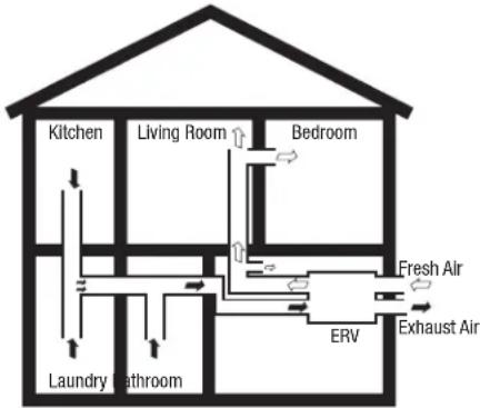
Fully Ducted System
-
This system uses an independent duct system for supply and exhaust air. The ERV/HRV is controlled independently of all other equipment. The best results are achieved when:
-
Each room of the space is serviced with a vent mounted in the ceiling or high on an interior wall (within 12" of the ceiling).
- Vents are located deep within a room, where they will not short circuit or create an uncomfortable draft.
flowchart
graph TD
    A["Kitchen"] --> B["Living Room"]
    B --> C["Bedroom"]
    C --> D["Fresh Air"]
    C --> E["Exhaust Air"]
    F["Laundry Bathroom"] --> G["ERV"]
    G --> H["Bedroom"]
    I["Water Supply"] --> J["Water Supply"]
    style A fill:#f9f,stroke:#333
    style B fill:#ccf,stroke:#333
    style C fill:#cfc,stroke:#333
    style D fill:#fcc,stroke:#333
    style E fill:#cff,stroke:#333
    style F fill:#ffc,stroke:#333
    style G fill:#cfc,stroke:#333
    style H fill:#fcc,stroke:#333
    style I fill:#ffc,stroke:#333
Extended Exhaust System
- This system uses the ERV/HRV in conjunction with a forced air furnace distribution system. In this system the ERV/HRV supply air to the house is introduced into the return duct of the forced air furnace. Separate ductwork (not included) is used to transfer stale air from the wet rooms to the ERV/HRV.

flowchart
graph TD
    A["Supply Air From Outside To Outside"] --> B["Extended Exhaust System"]
    B --> C["Stale Air Exhaust"]
    B --> D["Fresh Air"]
    B --> E["Return Duct"]
    E --> F["Furnace"]
    style A fill:#f9f,stroke:#333
    style B fill:#ccf,stroke:#333
    style C fill:#cfc,stroke:#333
    style D fill:#fcc,stroke:#333
    style E fill:#cff,stroke:#333
    style F fill:#ffc,stroke:#333
- Extended System, Continuous Ventilation: The furnace fan may not need to run continuously with this system. Check local code requirements. For improved supply air distribution during continuous ventilation mode, the furnace may be interlocked to the ERV/HRV. See Section 7 for interlock wiring and settings and Section 10 Control Wiring and Options.
- Extended System, Intermittent Ventilation: If the ERV/HRV is operated intermittently, the furnace fan should be interlocked with the ERV/HRV for good distribution of supply air during high-speed ventilation conditions.
Simplified System
- This system uses the furnace's return plenum for both supply air distribution and exhaust air collection. The exhaust air connection must be a minimum of 40 inches upstream of the supply air connection to avoid short circuiting of the fresh air.

flowchart
graph TD
    A["From Outside"] --> B["Simplified System"]
    C["To Outside"] --> B
    B --> D["Fresh Air"]
    B --> E["Exhaust Air"]
    B --> F["Furnace"]
    style B fill:#f9f,stroke:#333
    note right of B "Port configuration of ERV/HRV may vary from unit to unit"
    note right of F "40" Min
- Simplified System, Continuous Ventilation & Intermittent Operation: For proper supply air distribution with this system, and to prevent short circuiting in the return air duct, the furnace fan must run during ventilation mode. Interlock the furnace and unit in accordance with Section 7.
SECTION 3
Preparing the Unit
- Unpack unit from the carton and confirm that all pieces are present. In addition to the unit you should have:
Standard Filters Anti-Vibration Straps Removable Terminal Block
8 - Washers 4 - ½ Screws Drain Hose Assembly (HRV ONLY)
Core RVC8 Control Switch Instruction/Safety Sheet
- Choose the location for your unit. To ensure the best air and sound performance, it is recommended that the length of ducting and the number of elbows be kept to a minimum, the radius of each elbow be as large as possible for the installation, and that insulated hard ducting be used. The unit is designed to mount from the ceiling using the included anti-vibration mounting straps. Avoid mounting the unit under bedrooms or other quiet areas.
NOTE: The unit must be installed into a location that can be easily accessed once installed.
- No additional vibration deadening materials are needed for this fan.
SECTION 4
Mounting the Fan
- Using appropriate sized mounting screws at least #8 x 1.5" (not included) insert through the included washers and hanging strap grommets, then fasten to the mounting surface. If mounting to a material other than a wood joist use an appropriate mounting method as determined by a professional.
- Insert the included screws through the washers and bottom grommets of the straps, then fasten to the unit.
- Pull down vertically on each strap while lifting the bottom of the unit. Level the unit from right to left and front to back.
- To loosen strap, lift up on the buckle.
NOTE: Support unit and gently lift as you tighten each strap.


SECTION 5
Ducting

CAUTION: ALL DUCTING MUST COMPLY WITH LOCAL AND NATIONAL BUILDING CODES.
NOTE: The ducting from this fan to the outside of the building has a strong effect on the air flow, noise and energy use of the fan. Use the shortest, straightest duct routing possible for best performance, and avoid installing the fan with smaller ducts than recommended. Insulation around the ducts can reduce energy loss and inhibit mold growth. Fans installed with existing ducts may not achieve their rated air flow.
WARNING: MAKE SURE THE FRESH AIR INTAKE PORT COMPLIES WITH ALL LOCAL AND NATIONAL CODES AND IS LOCATED AT LEAST 6 FEET AWAY FROM SOURCES OF CONTAMINATION SUCH AS BUT NOT LIMITED TO: DRYER, FURNACE OR CENTRAL VACUUM EXHAUSTS, GAS APPLICANCES SUCH AS BBQ GRILLS, GARBAGE BINS OR OTHER EXHAUST PORTS.
NOTE: To ensure quiet operation of in-line and remote fans, each fan shall be installed using sound attenuation techniques appropriate for the installation. For bathroom and general ventilation applications, at least 8 feet of insulated flexible duct shall be installed between the exhaust or supply grille(s) and the fan.
- Connect the ducting to the unit's duct collars. Seal ducting to collars with appropriately rated tape. Use screws or suitable clamps to secure in place. Make sure the fresh air intake is connected to a properly installed intake port that is a suitable weather hood with insect screen to protect air intake. It is recommended that low restriction termination fittings be used.
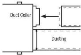
- Ensure duct joints and exterior penetrations are sealed with caulk or other similar material to create an air-tight path to minimize building heat loss or gain and to reduce the potential for condensation. Place/wrap insulation around duct and/or fan in order to minimize possible condensation buildup within the duct, as well as building heat loss or gain.
SECTION 6
Drain Connections (HRV Units Only)
Access to a drain or sump is required for condensate. Care should be taken to run the condensate tube where it cannot freeze. To install the drain assembly:

- Apply the rubber O-ring supplied to the flange of each drain spout.
- Insert the drain spouts through the holes in the drain pan.
- Use the provided nut to tightly secure the drain spout.
- Cut two lengths of 1/2" ID drain hose long enough to avoid kinking.
- Attach the hose to the drain spout by sliding it over the spout until it is tight to the bottom of the nut. Repeat for the other side.
- Secure the hose to the spout with the plastic tie wraps.
- Install the Tee Fitter in either of the two ways shown in the drawings.
- Attach the free end of the hose to the left fitting. Repeat for the other side.
- Use the remaining hose to form a "P" trap and terminate at the top of the tee.
- Pour approximately one cup of water into the drain assembly to form an air seal. This prevents gasses from being drawn into the unit.
NOTE: For single-drain units your unit might be equipped with just one drain and one drain plug. For these models, use the drain hose to form a P-shape after connecting the hose to the drain plug (the arc of the P should be wide enough so as not to cause a kink in the drain hose). Fix the P-shape with one of the (two) plastic cable ties provided, taking care not to pinch the hose when tightening the cable tie.
SECTION 7
Furnace Interlock

CAUTION: MAKE SURE UNIT IS UNPLUGGED BEFORE STARTING INSTALLATION.

CAUTION: ALL ELECTRICAL CONNECTIONS MUST BE MADE IN ACCORDANCE WITH LOCAL CODES, ORDINANCES, OR NATIONAL
ELECTRICAL CODE. IF YOU ARE UNFAMILIAR WITH METHODS OF INSTALLING ELECTRICAL WIRING, SECURE THE SERVICES OF A QUALIFIED ELECTRICIAN.
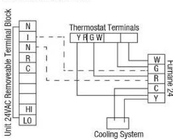
For simplified (return/return) duct systems, it is mandatory that the unit be interlocked with the furnace blower such that the furnace fan runs when the unit is on to distribute supply air throughout the space. For extended exhaust systems, furnace interlock is recommended. Refer to local building codes.
flowchart
graph TD
    A["Unit 24VAC Removable Terminal Block"] --> B["N"]
    A --> C["I"]
    A --> D["N"]
    A --> E["R"]
    A --> F["C"]
    A --> G["HI"]
    A --> H["LO"]
    B --> I["Thermostat Terminals"]
    C --> I
    D --> I
    E --> I
    F --> I
    G --> I
    H --> I
    I --> J["Furnane 24"]
    I --> K["W"]
    I --> L["G"]
    I --> M["R"]
    I --> N["C"]
    I --> O["Y"]
    J --> P["Cooling System"]
    K --> P
    L --> P
    M --> P
    N --> P
    O --> P
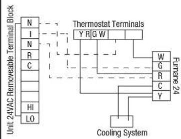
Standard Furnace Interlock Alternate
flowchart
graph TD
    A["Unit 242 WAC Removable Terminal Block"] --> B["N"]
    A --> C["I"]
    A --> D["N"]
    A --> E["R"]
    A --> F["C"]
    A --> G["HI"]
    A --> H["LO"]
    B --> I["Thermostat Terminals"]
    C --> I
    D --> I
    E --> I
    F --> I
    G --> I
    H --> I
    I --> J["Y R G W"]
    I --> K["W"]
    I --> L["G"]
    I --> M["R"]
    I --> N["C"]
    I --> O["Y"]
    J --> P["Furnane 24"]
    K --> P
    L --> P
    M --> P
    N --> P
    O --> P
    P --> Q["Cooling System"]
urnace Interlock
If the standard interlocking method has the unwanted effect of bringing on the AC, i.e. thermostats that do not isolate "G" from "Y", use the alternate method shown above.
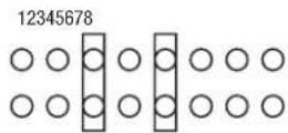
Depending on local Building Codes, you may choose to interlock whenever the unit is operating at any speed, or just high speed. Position 5: interlock at any unit speed; Position 6: interlock at unit high speed only.
NOTE: One jumper must be present in jumper range 1-4 and in jumper range 5-8. DO NOT alter jumper set 3.
SECTION 8
Balancing Air Flows
Once the ERV/HRV system is installed and the vapor barrier is completed, ensure the following:
- Close all windows, doors and fireplace dampers.
- Turn off any exhaust systems such as dryers, range hoods, bath fans and central vacuums.
- With multiple-speed forced air furnaces in Extended or Simplified systems, the furnace should operate at continuous low speed.
- During balancing, activate high speed on the unit by remote control or by temporarily installing a jumper wire between R and Hi on the unit's 10-wire, 24 VAC terminal block.
NOTE: If optional air filters are added at a later time, the unit's airflow will need to be re-balanced.
To balance the air flows, you will need a device to measure air flow. It is recommended to use either a magnehelic gauge or differential pressure digital manometer capable of measuring 0 to 0.5 inch of water (0-125 Pa). Depending on the device you are using, follow one of the two procedures below.
Magnehelic Gauge and Flow Grid:
- Disconnect the flex connector from the rigid duct before any branch ducts. Compress the flex duct and insert the flow grid. Tape the joint between the flow grid and ductwork.
- Mount the magnehelic gauge level and plumb. Join the hoses from the flow grid to the magnehelic gauge. The needle of the magnehelic gauge should read positively. Switch hose connections if the needle falls below zero.
- Record reading from gauge and adjust the motor speed to the desired CFM.
- Repeat the procedure for the next duct. Adjust motor speeds until air flow readings are equal or within 10% of each other.
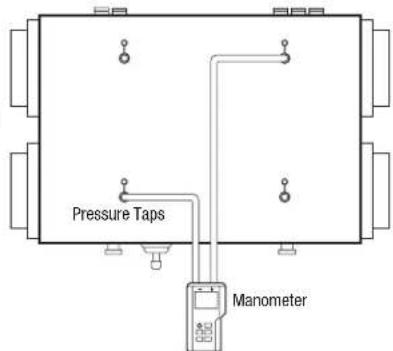
Differential Pressure Manometer or Magnehelic Gage and Units with Pressure Ports:
- Before placing the manometer, reset it to zero. If using a magnehelic gage, ensure the gage is placed plumb and level.
- According to the air flow to be measured, connect tubing from instrument to EXHAUST air flow or FRESH air flow pressure taps (see illustrations at right).
- If the readings on your instrument drop below zero, reverse the tubing connections.
- Take and record pressure readings from each air stream, consulting the air flow chart mounted on the unit's door to determine air flow.
- Balance air flows so that they equal or within 10% of each other.
NOTE: P/Airflow values are different for exhaust and supply air streams.
Unit Airflow Chart
Adjusting Fan Speed for Balancing and Capacity Requirements
For high-speed adjustment/balancing, use any means to initiate high speed (e.g. ES-M1, R—Hi jumper wire, or engage 24V R—Hi control), then:
-
Press and hold either the FRESH air or EXHAUST air push buttons (not both) for 3 Seconds to initiate SPEED ADJUST MODE.
-
Press the corresponding button to adjust the fresh air fan or the exhaust fan speed, thereby changing the air flow. Each press reduces motor speed until the default minimum is reached, at which point the motor will return to its peak speed. Allowing a brief pause between presses (about 0.5 seconds), you will press the adjust button about 70 times before reaching minimum speed. During the bala adjusting the fresh air motor or exhaust air
-
To exit balancing/speed adjust mode, stop pressing buttons for 10 seconds. This will place the unit back in operating mode with the new speeds saved to the circuit board's memory. Low-Speed Adjustment/Balancing. If low speed adjustment is desired, use a jumper wire (R—Lo) or remote control to put the unit into low speed and follow steps 1-3.
SECTION 10
Installing the Wall Control
Your unit includes a model RVC8 wall control. Your unit can also accommodate other 24 VAC controls and can be connected in Series or Parallel.

CAUTION: IF INSTALLING OTHER 24 VAC CONTROLS FOLLOW ALL INSTRUCTIONS INCLUDED WITH THE CONTROL AS WELL AS ANY LOCAL OR NATIONAL CODES THAT MAY APPLY.

CAUTION: FOR UNITS WITHOUT A RECIRCULATION DAMPER, TURN OFF RECIRCULATION FUNCTIONS IN CUSTOM SETTINGS.
WARNING: ROUTE CONTROL WIRING ACCORDING TO LOCAL BUILDING CODES.
Mounting the Control
-
Mount in a central location within the building.
-
Fits a standard 2" x 3" (nominal) electrical wall box (not included). While your wall control comes with a screwless face plate, you can substitute it with another to match any décor by using a flat screwdriver to pry off the original face plate and by removing the 5 mm screws securing the faceplate base.
-
Drywall anchors may be used where a wall box is not available.
Wiring
- Using a 3 mm flat head screwdriver, connect 4-conductor wire to the 12 VDC (4-wire) removable terminal block provided. Wiring the controls involves simply matching terminals on the control to those of the ERV/HRV terminal block (see right).

WARNING: DO NOT CROSS THE +12V/12 AND GROUND
(GND/G) WIRES. FOR RVC8 CONTROLS, DOING SO WITH POWER CONNECTED TO THE ERV/HRV MIGHT DAMAGE THE WALL CONTROL PROCESSOR.

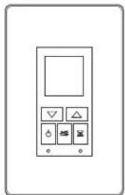
Press any key to turn on the backlight. The backlight will remain illuminated for 10 seconds after the last button is pushed.

Power

Use this key as a quick means to turn the ventilator off.
Mode
Use this button to enter the mode selection menu and to activate a chosen mode of operation.

Timer
Use this button to activate the ventilator into high speed for 20, 40 or 60 minutes. The timer button can also be used to turn off the high speed timer function.

Down Arrow
Use this button to decrease desired humidity setting, or to scroll through menu options.

Up Arrow
Use this button to increase desired humidity setting, or to scroll through menu options.
natural_image
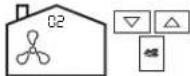
Simple line drawing of a control panel with buttons and indicators (no text or symbols)Press the mode button and you will see that the current mode icon and mode number (00-06) will flash. Use the arrow buttons to scroll up and down the numbered menu choices. To initiate a desired mode, press the mode button once more, or, after 4 seconds of no b will automatically activate the last mode option displayed.
CHOOSING A HUMIDITY SETTING
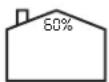
Press the up or down arrow key until the present humidity setting and % symbol are flashing. Use the up/down arrow buttons to adjust
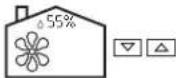
humidity setting in 5% increments. After 4 seconds of no button activity, presently selected humidity setting will be programmed. The current ambient humidity will then be displayed.
When ambient humidity exceeds the chosen setpoint a water drop icon will appear and the ventilator will operate in high speed until the humidity level drops below setpoint. Available humidity setting range: 20-80%.
In cases where humidity control is not desired or practical, use the arrow keys to toggle the humidity "setpoint" to one click above 80% or one click below 20%. Also use arrow keys to reactivate humidity control.
NOTE: Generally, a humidity setting of 40-60% is desired. While your ventilator is not a dehumidifier, ventilation can have the effect of reducing indoor humidity when exchanging moisture-laden air from the interior space with less humid, fresh air from outside.
OPERATION MODES

OFF: Ventilator is off, but the control itself is on and will display ambient humidity level.

STANDBY: Ventilator is idle. During this mode, a static pause icon will display. During standby mode the ventilator will temporarily switch to high speed on demand from the lumina humidity sensor or a timer.
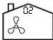
LOW SPEED: Ventilator runs in low speed continuously. During this mode, an animated 3-blade fan will display. During low speed mode the ventilator will temporarily switch to high speed on demand from the lumina humidity sensor or a timer.

HIGH SPEED: Ventilator runs in high speed continuously. During this mode, an animated 6-blade fan will display. Ventilator will remain in high speed on demand from the lumina humidity sensor or a timer and continue in high speed after the humidity/timer demand is met.

20 LO/40 STANDBY: Ventilator cycles continuously between 20 minutes of low speed operation and 40 minutes of standby operation. During low speed cycle, the fan 3-blade fan icon will animate and the pause symbol will flash twice every 5 seconds. During the standby cycle, the pause icon will be static and II flash twice every 5 seconds. During 20 lo/40 standby mode the ventilator will itch to high speed on demand from the lumina humidity sensor or a timer.
RECIRCULATION MODES

RECIRCULATION: Ventilator continuously recirculates air within the home and does not bring in air from outside, i.E. Air exchange does not occur. During this mode an animated cycling arrow will display. During recirculation mode the ventilator will temporarily switch to high speed on demand from the humidity sensor or an external timer.

20 LO/40 RECIRCULATION: Ventilator cycles continuously between 20 minutes of low speed operation and 40 minutes of recirculation operation. During the low speed cycle, the fan will animate and the recirculation ring will flash twice every 5 seconds. During the recirculation cycle, the recirculation arrow will animate and
the fan icon will flash twice every 5 seconds. During 20 lo/40 recirculation mode the ventilator will temporarily switch to high speed on demand from the lumina humidity sensor or a timer.
For timed high speed operation, press the hourglass button once for 20 minutes, twice for 40 minutes, or three times for 60 minutes. Hourglass icons will appear from left to right at the bottom right of the LCD display and a high speed fan icon will appear on the screen. After 3 seconds of

no button activity the high speed cycle will begin. As each 20 minute cycle expires, one hourglass icon will disappear from right to left. You can manually turn off the timer cycle by pressing the hour glass button until all the hourglass icons disappear.
If you would like to view or change modes during a high speed call, simply use the mode and arrow keys and the chosen mode will resume/commence after the timer cycle has expired.
NOTE: Additional timers are compatible with your control, however, the control will not indicate that these external timers are active (i.E. It will continue to display present mode of operation only). You can change the desired mode of operation during a timer cycle; it will commence after the timer cycle has expired.
MAINTENANCE INDICATOR/RESETTING MAINTENANCE CLOCK
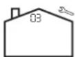
Your control has a maintenance run clock (it only counts time when the ventilator is turned on). Factory default for the maintenance clock is 3 months, at which time a wrench icon will appear in the upper right of the LCD screen and a yellow led will light. This indicates that it is time to check your ventilator to see if it needs cleaning and to see if your filters

20/40
need to be cleaned or replaced. Press and hold the power button for 5 seconds to reset the maintenance clock. Some units feature a red LED that will light after 3 months if the initial service reminder is not turned off.
If the electrical service to the ventilator is for some reason interrupted, the mode of operation active in the wall control at the time of the interruption will resume when the electrical service to the ventilator resumes. Any custom settings will have been saved.
CUSTOM SETTINGS
The control allows adjustments to customize its use for unique circumstances. Any of these changes are written into the control's memory but can be changed an infinite number of times. We recommend that only a qualified technician make these adjustments as they can affect the nature of the ventilator's performance. The customizable features include:
- Adjusting the run time of the maintenance clock
- Calibrating the humidity sensor
- Turning off/on recirculation functions.

To access the custom settings menu, simultaneously press and hold the up and down arrow buttons for 15 seconds. You will note that the backlight would have turned on after 10 seconds. Once in the custom settings menu, use the arrow buttons to navigate among choices for a given setting. Pressing the mode button will preserve factory settings or initiate any change and will move you on to the next customized feature. After 5 seconds of no button activity, current settings will be written and the control will resume regular operation as programmed.
Once you are in the custom settings mode the first option will be maintenance clock. You will see the factory setting of this feature: 3 months. To keep factory setting, press the mode button or use the up and down arrow buttons to change the setting in the range of 1-12 months. Once any desired change to the setting is in place (if any), press the mode button.
CALIBRATING THE HUMIDITY SENSOR
If calibration is not desired, skip this step by simply pressing the mode button to keep factory calibration active. If calibration is desired, use the up and down arrow keys to calibrate the humidity sensor in 5% increments. To program any changes, press the mode button.
TURN OFF/ON RECIRCULATION FUNCTIONS
You will now see an animated recirculating arrow indicating that the recirculation by factory default is enabled. Use the up and down arrow keys to turn off the recirculation functions (static arrow) or on (animated arrow).

As noted previously, recirculation functions must be turned off for use with ventilators that do not have a recirculation damper. For such units, use of recirculation functions would only result in full-time, low-speed operation.
SECTION 11
Status LED
- Your control board is equipped with status lights to indicate mode of operation as follows:
| CONDITION LED AND STATUS | |
| NO LED UNIT/TRANSFORMER IS | NOT POWERED |
| UNIT OFF Red is off, Green is bl | inking slow, every 1 s. Also indicates processor is programmed and running. |
| STANDBY Green is OFF. Red led | is blinking slow, every 1 s. |
| EXCHANGE LOW SPEED Green | ON. Red blinking slow, every 1 s. |
| EXCHANGE HIGH SPEED Green | ON. Red blinking fast. |
| DEFROST* | Green ON, Red ON. |
| RECIRCULATION HIGH SPEED* | Red led ON, Green led blinking fast. |
| *Where available | |
SECTION 12
Start-Up
- Ensure the controls are connected in accordance with Section 7 and/or 10.
- For electrical hook-up, plug into a properly grounded 120 volt receptacle.
- Ensure that the machine is piped to an adequate drainage source, i.e. through the drain hose supplied.
SECTION 13
Operating Your System
It is recommended that the unit run on low speed at all times to ensure a steady supply of fresh air and removal of indoor pollutants. How much a home needs ventilation can depend on several factors such as number of inhabitants, cooking habits, hobbies, presence of pets, opening windows, etc. so no two households are necessarily the same for the amount and frequency of ventilation they need. Observance of moisture on windows, lingering odors and a sensation of stuffy, stagnant air are all signs for the need of ventilation in general or increased ventilation in specific cases. The controls for your ventilation system offer means to regulate how much and how often the home is ventilated.
The included control is equipped with a dehumidistat, or "d-stat". A d-stat monitors ambient relative humidity (RH) and has selectable settings, generally 30%-80% RH. When ambient
humidity is detected above the setpoint, it will trigger high speed in the ventilator. The unit will run in high speed until the ambient air returns to the setpoint RH. Your ventilator is not a dehumidifier, however ventilating can have a dehumidifying effect by simply removing high RH air from the space, particularly during cooler/cold seasons when outdoor humidity is typically lower than indoor humidity. Typical dehumidistat settings are as follows:
Winter Operation: 40% - 60%. Lower settings may be necessary in colder zones to keep windows free of condensation. If you notice the air is uncomfortably dry in winter, you might set humidity to a higher level or choose an operation mode above which operates the ventilator less or for shorter periods.
Spring/Fall Operation: 50% - 60%.
Summer Operation: For air conditioned homes run the ERV/HRV as recommended for winter operation, i.e. continuous low speed or use a 20/40 setting. In homes without air conditioning, there is no need to run the ERV/HRV during the day when windows are open. If the ERV/HRV is connected to the bathrooms(s) or kitchen, use the standby setting. The typical dehumidistat summer setting is 65%-80% or OFF.
SECTION 14
Use and Care

CAUTION: MAKE SURE UNIT IS UNPLUGGED BEFORE SERVICING.
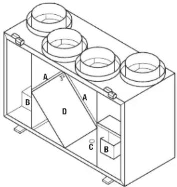
NOTE: Exact location of components will vary according to the specific unit.
natural_image
Isometric technical drawing of a mechanical housing with labeled components (A, B, C, D), no readable text or symbols present.- Filters (A): Dirty filters can reduce ventilation efficiency, result in unbalanced airflow and damage or shorten the life of the motors. Filters are located either on top or below the core depending on your exact model and remove easily by opening the front cover of the unit and sliding out.
Polyester Filters: Vacuum every three months. Replaced every 1-3 years.
Option MERV Air Filters: If optional air filters have been installed, they should be replaced every 3 months. When replacing, take special note of the airflow direction. - Fan (B): Wipe all parts with a dry cloth or gently vacuum the fan. NEVER IMMERSE ELECTRICAL PARTS IN WATER. No other service is required as these fans are designed to operate continuously without lubrication.
- Condensate Drain (C) (HRV UNITS ONLY): Twice per year wipe clean the condensate drain pan. Check the condensate drain and tubing to ensure they are free flowing. The tubing must have an "S" or loop that traps a quantity of water to prevent air from entering the unit via this tubing.
- Recovery Core (D): The core (located behind the cover) should be removed and cleaned at least once a year. Unlatch the latch(es) and slide the door to right to release from hinges and clean as follows:
ERV Units: Clean by vacuuming at least once a year. DO NOT USE SOAP, WATER OR ANY CLEANING AGENTS ON THE FIBER-MEDIA CORE.
HRV Units: Clean using a mild detergent in cold water at least once a year. Make sure the core is completely dry before re-installing into the unit.
When re-installing the core make sure the arrow on the core is pointing to the top of the unit.
- Exterior Hoods: Regularly check the outside vents and clean any obstructions such as grass, leaves or other debris. Do not replace the screen with mesh smaller than 1/4" as this will restrict airflow. During winter operation, ensure snow and frost does not build up and restrict or block openings.
- Grills & Duct Work: Clean the grills when they are dusty or greasy with soap and water. Check for punctures in the insulation jacket on the fresh air and exhaust air ducts. Repair any punctures using foil tape.
- Annual Servicing: Your ERV/HRV should undergo annual general servicing by an accredited contractor. This servicing should include the following:
a) The six maintenance items above.
b) A general check for proper operation. Controls and electrical connections should be inspected.
c) Verification that intake and exhaust air flows are properly balanced.
d) Re-balancing as necessary.

CAUTION: ONLY QUALIFIED TECHNICIANS SHOULD SERVICE CONTROLS OR INTERNAL COMPONENTS.
Troubleshooting Guide
| Trouble Probable Cause Suggested Remedy | ||
| The humidity level seems too low. ERV/HRV air flows incorrectly | balanced. Balance air flow(s). | |
| Dehumidistat control set too low. Increase dehumidistat. | ||
| Lifestyle of the resident(s). Humidifiers may need to be added. | ||
| The humidity level seems too high. ERV/HRV air flows incorrectly | balanced. Balance airflow. | |
| ERV/HRV not properly sized for the application. Set dehumidistat. | ||
| High humidity areas not ventilated properly. Cover pools etc. when not in use. | ||
| Lifestyle of the resident(s). Avoid hanging clothes to dry, storing wood and venting clothes dryer inside. | ||
| Dehumidistat is not working. | ||
| The house is dry but the basement wet. | High humidity during summer months | Install a programmable timer on 12-hour cycle. On at night. Off during the day. |
| Partially close some grills upstairs, open grills in basement. | ||
| The Controls or Dehumidistat are not working. Incorrect connection of outside low voltage wiring between ERV/HRV and dehumidistat. | Check control wiring for short | |
| Check wall switch for correct connection. | ||
| Check wires are connected to proper terminals at the ERV/HRV. | ||
| There is Frosting up of the ERV/HRV and/or duct(s). ERV/HRV air flows incorrectly balanced. Balance ERV/HRV. | ||
| Function (where present). Install back draft dampers as needed. | ||
| Check defrost system. | ||
| Note minimal frost build up is expected on cores before unit initiates defrost cycle function. | ||
| The supply air feels cool. ERV/HRV air flows incorrectly balanced. Balance ERV/HRV. | ||
| Locate grills high on walls or in ceiling. | ||
| If supply air is installed into return line of furnace, furnace fan must run continuously on low speed. | ||
| The outside duct has ice build up or condensation. | Improperly installed vapor barrier around insulated duct. | Tape all joints. |
| Ensure that vapor barrier is completely sealed and insulated. | ||
| There is water in the bottom of ERV/HRV. | Drain pans are plugged. | Look for kinks in the line. |
| Incorrect connections of ERV/HRV's drain lines. | Check water drain connections. | |
| ERV/HRV is not level. | ||
| Drain lines plugged. | ||
| ERV/HRV heat exchange core improperly installed. | ||
| There is poor air flow(s). | ERV/HRV airflow incorrectly balanced. | Tape all joints. |
| Filters need to be cleaned. | Use proper air flow measuring equipment. | |
| Mesh on outside hoods needs to be cleaned. | Open grills. | |
| Grills are closed. | Remove obstructions in duct(s), hoods(s), and grill(s). | |
| Present dampers are closed. | Balance air flows. | |
| Low power supply. | Clean filter. | |
| Wrong-size ducting. | Have a professional look at the system. | |
| Under-sized ERV/HRV. | ||
| ERV/HRV is not working. | ||
LIMITED WARRANTY
WHAT THIS WARRANTY COVERS: This product is warranted against defects in workmanship and/or materials.
HOW LONG THIS WARRANTY LASTS: This warranty extends only to the original purchaser of the product and lasts for one (1) year from the date of original purchase or until the original purchaser of the product sells or transfers the product, whichever first occurs.
WHAT AIR KING WILL DO: During the warranty period, Air King will, at its sole option, repair or replace any part or parts that prove to be defective or replace the whole product with the same or comparable model.
WHAT THIS WARRANTY DOES NOT COVER: This warranty does not apply if the product was damaged or failed because of accident, improper handling or operation, shipping damage, abuse, misuse, unauthorized repairs made or attempted. This warranty does not cover shipping costs for the return of products to Air King for repair or replacement. Air King will pay return shipping charges from Air King following warranty repairs or replacement
ANY AND ALL WARRANTIES, EXPRESSED OR IMPLIED (INCLUDING, WITHOUT LIMITATION, ANY IMPLIED WARRANTY OF MERCHANTABILITY), LAST ONE YEAR FROM THE DATE OF ORIGINAL PURCHASE OR UNTIL THE ORIGINAL PURCHASER OF THE PRODUCT SELLS OR TRANSFERS THE PRODUCT, WHICHEVER FIRST OCCURS AND IN NO EVENT SHALL AIR KING'S LIABILITY UNDER ANY EXPRESS OR IMPLIED WARRANTY INCLUDE (I) INCIDENTAL OR CONSEQUENTIAL DAMAGES FROM ANY CAUSE WHATSOEVER, OR (II) REPLACEMENT OR REPAIR OF ANY HOUSE FUSES, CIRCUIT BREAKERS OR RECEPTACLES. NOTWITHSTANDING ANYTHING TO THE CONTRARY, IN NO EVENT SHALL AIR KING'S LIABILITY UNDER ANY EXPRESS OR IMPLIED WARRANTY EXCEED THE PURCHASE PRICE OF THE PRODUCT AND ANY SUCH LIABILITY SHALL TERMINATE UPON THE EXPIRATION OF THE WARRANTY PERIOD.
Some states and provinces do not allow limitations on how long an implied warranty lasts, or the exclusion or limitation of incidental or consequential damages, so these exclusions or limitations may not apply to you. This warranty gives you specific legal rights. You may also have other rights which vary from state to state and province to province. Proof of purchase is required before a warranty claim will be accepted.
CUSTOMER SERVICE:
Toll-Free (800) 465-7300
Our Customer Service team is available to assist you with product questions, service center locations, and replacement parts. They can be reached Monday through Friday, 8am-4pm Eastern. Please have your model number available, as well as the type and style (located on the label inside of your product).
Please do not return product to place of purchase.
www.airkinglimited.com
PARTS FOR DISCONTINUED, OBSOLETE AND CERTAIN OTHER PRODUCTS MAY NOT BE AVAILABLE. DUE TO SAFETY REASONS, MANY ELECTRONIC COMPONENTS AND MOST HEATER COMPONENTS ARE NOT AVAILABLE TO CONSUMERS FOR INSTALLATION OR REPLACEMENT.
Installer: Installation Date:
Place of Purchase: Model Number:
Replacement Parts
| Model AKEV95 | |||
| # Qty. Description Replacement Part # | |||
| 1 1 Door Latch 5S7758001 | |||
| 2 2 Hinge Knuckle and Pins 5S7760001 | |||
| 3 1 Circuit Board 5S7758002 | |||
| 4 2 Motor 5S7758003 | |||
| 5 1 Fuse Holder 5S7760002 | |||
| 6 1 Fuse (2 5 Amp) 5S7760003 | |||
| 7 1 10 Position Screw Terminal 5S7760004 | |||
| 8 1 4 Position Screw Terminal 5S7760005 | |||
| 9 1 Striker Plate 5S7758004 | |||
| 10 | 1 Core | 5S7758005 | |
| 11 | 1 Door Switch | 5S7760006 | |
| 12 | 1 Door Assembly 5S7758006 | ||
| 13 | 2 Core Filter* | 5S7760007 | |
| 14 | 2 Motor Capacitor | 5S7758007 | |
| 19 | 1 | RVC8 Wall Control | 5S7760008 |
| Model AKEV160 | |||
| # Q | y. Description Replacement Part # | ||
| 1 | 2 Motor | 5S7759001 | |
| 2 | 2 Capacitor | 5S7759002 | |
| 3 | 1 Circuit Board 5S7759003 | ||
| 4 | 1 10 Position Screw Terminal 5S7760004 | ||
| 5 | 1 4 Position Screw Terminal 5S7760005 | ||
| 6 | 2 Hinge Knuckle and Pins 5S7760001 | ||
| 7 | 2 Draw Latch | 5S7759004 | |
| 8 | 2 Keeper | 5S7759005 | |
| 9 | 1 Door Switch | 5S7760006 | |
| 10 | 1 Core | 5S7759006 | |
| 11 | 1 Door Assembly 5S7759007 | ||
| 12 | 1 Fuse Holder 5S7760002 | ||
| 13 | 1 Fuse (2.5 amp) 5S7760003 | ||
| 14 | 1 Transformer 5S7759001 | ||
| 15 | 2 Core Filter* | 5S7760007 | |
| 19 | 1 | RVC8 Wall Control | 5S7760008 |
| Model AKHV160 | |||
| # Qty. Description Replacement Part # | |||
| 1 2 Motor | 5S7759001 | ||
| 2 2 Capacitor | 5S7759002 | ||
| 3 1 Circuit Board 5S7759003 | |||
| 4 1 10 Position Screw Terminal 5S7760004 | |||
| 5 1 4 Position Screw Terminal 5S7760005 | |||
| 6 2 Hinge Knuckle and Pins 5S7760001 | |||
| 7 2 Draw Latch | 5S7759004 | ||
| 8 2 Keeper | 5S7759005 | ||
| 9 1 Door Switch | 5S7760006 | ||
| 10 | 1 Core | 5S7760009 | |
| 11 | 1 Door Assembly 5S7759007 | ||
| 12 | 1 Fuse Holder 5S7760002 | ||
| 13 | 1 Fuse (2.5 amp) 5S7760003 | ||
| 14 | 1 Transformer 5S7759001 | ||
| 15 | 2 Core Filter* | 5S7760007 | |
| 16 | 1 Drain Fitting 5S7759010 | ||
| 17 | 1 Motor Damper | 5S7759011 | |
| 18 | 2 | Damper Torsion Springs | 5S7759012 |
| 19 | 1 | RVC8 Wall Control | 5S7760008 |
- Core filters come in 2 per package and need to be cut to size. HRV filters are located in lower quadrants of unit.

- IMPORTANT INSTRUCTIONS - OPERATING MANUAL
- READ AND SAVE THESE INSTRUCTIONS
- GENERAL SAFETY INFORMATION
- WARNING: TO REDUCE THE RISK OF FIRE, ELECTRIC SHOCK AND INJURY TO PERSON, OBSERVE THE FOLLOWING:
- WARNING: TO REDUCE THE RISK OF FIRE, REMOVE ANY SHIPPING MATERIAL THAT MAY BE PRESENT INSIDE THE UNIT.
- CAUTION: FOR GENERAL VENTILATING USE ONLY. DO NOT USE TO EXHAUST HAZARDOUS OR EXPLOSIVE MATERIALS AND VAPORS.
- WARNING: TO REDUCE THE RISK OF FIRE, ELECTRIC SHOCK, DO NOT USE THIS FAN WITH ANY SOLID-STATE SPEED CONTROL DEVICE.
- WARNING: DO NOT USE IN KITCHENS.
- WARNING: FOR INDOOR INSTALLATIONS ONLY.
- INSTALLATION CONSIDERATIONS:
- SAVE THESE INSTRUCTIONS
- INSTALLATION INSTRUCTIONS
- SECTION 1
- Preparing the Installation Area
- SECTION 2
- Installation Options
- Fully Ducted System
- Extended Exhaust System
- Simplified System
- SECTION 3
- Preparing the Unit
- SECTION 4
- Mounting the Fan
- SECTION 5
- Ducting
- CAUTION: ALL DUCTING MUST COMPLY WITH LOCAL AND NATIONAL BUILDING CODES.
- WARNING: MAKE SURE THE FRESH AIR INTAKE PORT COMPLIES WITH ALL LOCAL AND NATIONAL CODES AND IS LOCATED AT LEAST 6 FEET AWAY FROM SOURCES OF CONTAMINATION SUCH AS BUT NOT LIMITED TO: DRYER, FURNACE OR CENTRAL VACUUM EXHAUSTS, GAS APPLICANCES SUCH AS BBQ GRILLS, GARBAGE BINS OR OTHER EXHAUST PORTS.
- SECTION 6
- Drain Connections (HRV Units Only)
- SECTION 7
- Furnace Interlock
- SECTION 8
- Balancing Air Flows
- Magnehelic Gauge and Flow Grid:
- Differential Pressure Manometer or Magnehelic Gage and Units with Pressure Ports:
- Adjusting Fan Speed for Balancing and Capacity Requirements
- SECTION 10
- Installing the Wall Control
- Mounting the Control
- Wiring
- Power
- Mode
- Timer
- Down Arrow
- Up Arrow
- CHOOSING A HUMIDITY SETTING
- OPERATION MODES
- RECIRCULATION MODES
- MAINTENANCE INDICATOR/RESETTING MAINTENANCE CLOCK
- CUSTOM SETTINGS
- CALIBRATING THE HUMIDITY SENSOR
- TURN OFF/ON RECIRCULATION FUNCTIONS
- SECTION 11
- Status LED
- SECTION 12
- Start-Up
- SECTION 13
- Operating Your System
- SECTION 14
- Use and Care
- CAUTION: MAKE SURE UNIT IS UNPLUGGED BEFORE SERVICING.
- CAUTION: ONLY QUALIFIED TECHNICIANS SHOULD SERVICE CONTROLS OR INTERNAL COMPONENTS.
- LIMITED WARRANTY
- CUSTOMER SERVICE:
- Replacement Parts
Brand : Air King
Model : AKEV160
Category : Fan