
EFX PA8BX - Audio Installation Kit Scosche - Free user manual and instructions
Find the device manual for free EFX PA8BX Scosche in PDF.


| Product Type | Car Audio Amplifier |
| Brand | Scosche |
| Model | EFX PA8BX |
| Dimensions (Approx.) | 12.0 x 8.0 x 2.5 in (30.5 x 20.3 x 6.4 cm) |
| Weight (Approx.) | 5.5 lbs (2.5 kg) |
| Power Supply | 12V DC (vehicle electrical system) |
| Peak Power Output | 800 Watts |
| RMS Power Output | 400 Watts x 2 channels @ 4 ohms |
| Amplifier Class | AB |
| Number of Channels | 2 |
| Frequency Response | 20 Hz - 20 kHz |
| Total Harmonic Distortion | < 0.05% |
| Signal-to-Noise Ratio | > 90 dB |
| Input Sensitivity | 200 mV - 6 V |
| Low-Pass Filter | 50 Hz - 250 Hz |
| High-Pass Filter | 50 Hz - 250 Hz |
| Bass Boost | 0 - 12 dB |
| Speaker Impedance | 4 - 8 ohms |
| Fuse Rating | 30 A x 2 |
| Mounting | Screw mount, 4 points |
| Maintenance | Clean with a dry, lint-free cloth. Avoid liquids. |
| Safety | Disconnect battery before installation. Ensure proper ventilation. |
| Warranty | 1 Year Limited Warranty |
| Included Accessories | Mounting hardware, remote level control, user manual |
Frequently Asked Questions - EFX PA8BX Scosche
User questions about EFX PA8BX Scosche
0 question about this device. Answer the ones you know or ask your own.
Ask a new question about this device
Download the instructions for your Audio Installation Kit in PDF format for free! Find your manual EFX PA8BX - Scosche and take your electronic device back in hand. On this page are published all the documents necessary for the use of your device. EFX PA8BX by Scosche.
USER MANUAL EFX PA8BX Scosche
AMPLIFIER INSTALLATION KITS
PARTS LISTS
142PA4BX WIRING KIT
• 17 ft. 4GA Power Cable with Ring Terminal
• 2ft. 4GA Ground Cable with Ultimate Ground Pre-terminated
• 17 ft. Remote Turn-On Wire
• 17 ft. Core Twisted Interconnect
• 6 ft. Split Loom Tubing
• (1) Mini-ANL Fuse Holder
• (1) 100A Mini-ANL Fuse
• (1) Snap-in Firewall Grommet
• (2) Power/Ground Spade Terminals
• (1) Remote Spade Terminal
• (1) Remote Butt Connector
• (2) Fuse Holder Mounting Screws
• (3) UGT Self-Tapping Screws
• (6) 8" Cable Ties
142PA8BX WIRING KIT
• 17 ft. 8GA Power Cable with Ring Terminal
• 2 ft. 8GA Ground Cable with Ultimate Ground Pre-terminated
• 17 ft. Remote Turn-On Wire
• 17 ft. Core Twisted Interconnect
• 6 ft. Split Loom Tubing
• (1) Mini-ANL Fuse Holder
• (1) 60A Mini-ANL Fuse
• (1) Snap-in Firewall Grommet
• (2) Power/Ground Spade Terminals
• (1) Remote Spade Terminal
• (1) Remote Butt Connector
• (2) Fuse Holder Mounting Screws
• (2) UGT Self-Tapping Screws
• (6) 8" Cable Ties
142PA10BX WIRING KIT
• 17 ft. 10GA Power Cable with Ring Terminal
• 2 ft. 10GA Ground Cable with Ultimate Ground Pre-terminated
• 17 ft. Remote Turn-On Wire
• 17 ft. Core Twisted Interconnect
• 6 ft. Split Loom Tubing
• (1) In-Line ATC Fuse Holder
• (1) 30A ATC Fuse
• (1) Snap-in Firewall Grommet
• (2) Power/Ground Spade Terminals
• (1) Remote Spade Terminal
• (1) Remote Butt Connector
• (2) UGT Self-Tapping Screws
• (6) 8" Cable Ties
GENERAL WIRING TIPS
Wiring your vehicle can be the most time consuming part of an installation, therefore certain good habits should be adhered to. The following basic tips can make the difference between an installation lasting on day or a lifetime.
- RCA audio cables and power lines should be run separately. 12 volt power lines, when run next to RCA audio or speaker wires, can induce a hum into the signal path of the system (radiated noise), even with well shielded wires. Keeping these wires a minimum of six inches apart will help ensure that power line interference will not be present in the system.
- All wiring, whether power, speaker or RCA audio cables should be kept as far as possible from other high voltage areas of the car's factory wiring. These can also induce noise into the system.
- Make certain that wiring is never run through openings which have rough metal edges, like fire walls, trunk walls, etc. Also, beware that wiring may get pinched beneath seat tracks, clutch and brake pedals, etc. Use vinyl tubing and grommets whenever necessary.
- When making any connection, use crimp connectors, or solder all connections and properly cover with heat shrink tubing or electrical tape.
TOOLS & PREPARATION
The following is a list of common tools and supplies required when doing car audio installations:
- Wire strippers
- Wire crimpers
-
Soldering iron/gun
• Cordless drill/drill bits -
Read all manufacturer warnings regarding vehicle's electrical service, air bags, ABS brakes, engine & body computers.
-
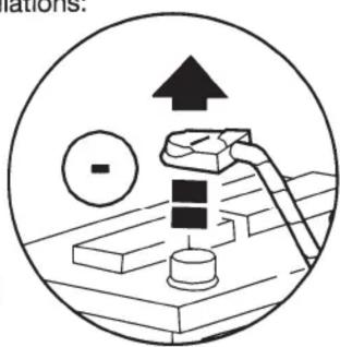
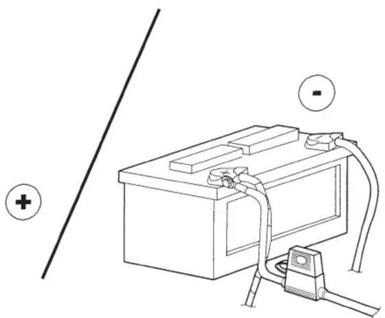
Disconnect Negative (-) battery terminal before beginning your installation (Figure 1).
-
Wear eye and skin protection.
FIGURE 1

IMPORTANT! DO NOT RETURN PRODUCT TO THE RETAILER
IF YOU NEED ASSISTANCE OR REPLACEMENT PARTS CALL US TOLL FREE: 1-800-621-3695 X3
HOURS MON-FRI 8AM-5:30PM (PST) SATURDAY 8AM-2PM (PST)
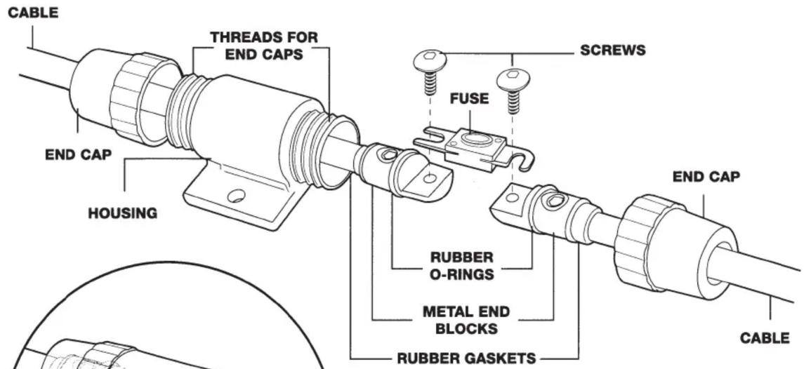
FIGURE 2 - EFX MINI ANL FUSE HOLDER FOR 142PA4BX & 142PA8BX
INSTALLATION:
- Before making battery connection, unscrew both end caps
- Push one side wire through fuse holder body for fuse installation.
- Pull back, check grommet/o-ring seals and fasten caps again.
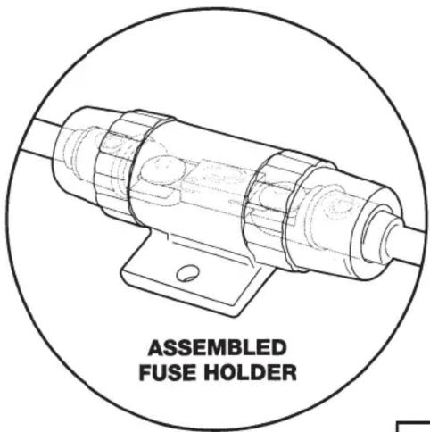

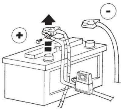
FIGURE 4 BATTERY CONNECTIONS
natural_image
Line drawing of a battery connected to a plug, with a positive terminal and a minus symbol (no text or labels)
USING THE WIRING KIT
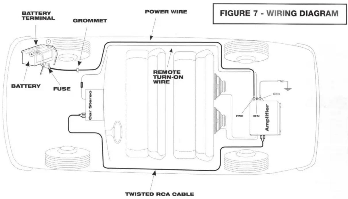
SEE WIRING DIAGRAM ON PAGE 3, FIGURE 7
POWER CABLE
- Pre-plan power cable routing for the shortest possible distance between the battery and the amplifier while avoiding any moving parts or sharp metal edges.
- Next, look for a suitable location on the battery-side of the vehicle's fire wall such as a rubber grommet or pass-through to route the cable from the engine compartment into the interior. If no suitable existing location is available, then you may be required to drill a hole for the power cable where there are no obstructions.
2A. (Grommet installation) Double-check for any obstacles on both the interior and engine compartment sides of the firewall before drilling any holes. Use the appropriate sized drill bit for your kit (5/16"=10GA., 3/8"=8GA., 12 "=4GA.) and drill a hole for the grommet. Snap the supplied cable grommet into the drilled hole from the engine compartment side. - Route the power cable from the battery to the amp avoiding any moving parts or areas that could pinch or cut the cable. To conceal cable, it may be necessary to remove vehicle trim panels, sill plates, or other parts. Call tech support if you require assistance: (800) 621-3695 Ext 3. Use the supplied cable ties to secure the cable and use the supplied split loom tubing to protect the cable under the hood.
4 (Amp connection) Ensure the battery end of the cable is NOT connected and/or there is not fuse installed in fuse holder. At the amplifier, cut any excess cable length (if needed), and crimp the supplied barrier spade terminal with the RED boot onto the end of the cable. Unscrew the amps 12V battery terminal and attach the power cable (See Fig. 6, Pg. 3) Some Amplifiers use discreet cable-clamp (set-screw) style connections. If so the barrier spades are not required. In this case, strip back a small amount of cable insulation, insert the exposed cable and simply tighten the clamping nut to secure. - (Battery connection) Ensure the battery Negative has been removed help prevent short circuits. Carefully unscrew the Positive battery terminal and attach the pre-connected ring terminal of the power cable to the battery. For the 142PA4BX and 142PA8BX 4GA/8GA kits with Mini ANL fuse holder we recommend installing the fuse before the battery positive connection. Keep the battery Negative removed to ensure the circuit is not live. (See Fig. 2/3/4 on Pg. 2)
- (Fuse holders) See Fig. 2/3 on Pg. 2 for Fuse installation/removal.
GROUND CABLE
- Pre-plan Ground cable routing for the shortest possible distance between the amplifier and clean, non-painted vehicle chassis metal. The 2ft Ground cable included with this kit is pre-terminated with an Ultimate Ground Terminal for the best contact and easy installation.
- Double check under/behind the location for obstructions before screwing down the ground cable. Use a file, grinder or other method to ensure clean, non-painted chassis metal and then use the supplied self-tapping screws to secure the ground cable to the vehicle. (See Fig. 5 Pg. 3)
- At the amplifier, cut any excess cable length (if needed), and crimp the supplied barrier spade terminal with the BLACK boot onto the end of the cable. Unscrew the amp's Ground terminal and attach the ground cable (See Fig. 6, Pg. 3) Some Amplifiers use discreet cable-clamp (set-screw) style connections. If so, the barrier spades are not required. In this case, strip back a small amount of cable insulation, insert the exposed cable and simply tighten the clamping nut to secure.
EFX TWISTED RCA AUDIO CABLES AND REMOTE TURN-ON LEAD
- Route the supplied EFX RCA audio cable and the supplied blue turn-on lead from the radio cavity to the amplifier location, along with the speaker wires, if possible.
NOTE: Keep audio cables away from all types of power sources to prevent radiated noise from entering the system. Also, keep these wires away from all moving parts to avoid damage. - Connect the RCA audio cables to the stereo's Right and Left RCA outputs. Connect the Blue remote turn-on wire to the stereo's amp remote or power antenna control wire.
NOTE: Make note of what color RCA audio cable is connected to Right and Left channel outputs.
CAUTION: If your stereo does not have RCA outputs, do not cut off the ends of the Scosche audio cable and connect/splice them to any speaker wires!!! You will need a line output converter to convert the speaker wires of the stereo into RCA line-level outputs.
-
At the amplifier, connect the RCA cables to the Amplifier's Right and Left inputs.
-
Connect the Blue remote turn-on lead coming from the stereo to the amplifier's remote turn-on lead. For more information regarding the wiring connectors of your amplifier, please consult the amplifier's installation manual.
LIMITED WARRANTY
Scosche Industries, Inc. warrants this product to be free from defects in material and workmanship for a period of 90 days from date of purchase. All Scosche products are sold with the understanding that the purchaser has independently determined the suitability of such products. This warranty does not cover any expenses incurred in the removal and reinstallation of the product. This warranty is offered to the original purchaser of the product only.
This warranty does not apply to the product which has been damaged by accident, or which has been misused, altered, or installed improperly. If the product should prove defective within the warranty period, return the product with sales slip, postage prepaid to Scosche Industries, Inc. Your dated sales slip/proof of purchase will establish your warranty eligibility. Scosche, at its option, will replace or repair the product free of charge and return the product to you postage paid. In no event shall Scosche be responsible for claims beyond the replacement value of the defective product or in any way be held liable or responsible for consequential or incidental damages.
No express warranties and no implied warranties, whether for fitness or any particular use, or otherwise, except as set forth above (which is made expressly in lieu of all other warranties) shall apply to products sold by Scosche. No waiver, alteration, addition, or modification of the foregoing conditions shall be valid unless made in writing and signed by an executive officer of Scosche Industries, Inc.
No salesperson, representative, or agent of Scosche is authorized to give any guarantee, warranty, or make any representation contrary to the above.

- AMPLIFIER INSTALLATION KITS
- PARTS LISTS
- 142PA4BX WIRING KIT
- 142PA8BX WIRING KIT
- 142PA10BX WIRING KIT
- GENERAL WIRING TIPS
- TOOLS & PREPARATION
- IMPORTANT! DO NOT RETURN PRODUCT TO THE RETAILER
- INSTALLATION:
- USING THE WIRING KIT
- SEE WIRING DIAGRAM ON PAGE 3, FIGURE 7
- POWER CABLE
- GROUND CABLE
- EFX TWISTED RCA AUDIO CABLES AND REMOTE TURN-ON LEAD
- LIMITED WARRANTY
Brand : Scosche
Model : EFX PA8BX
Category : Audio Installation Kit