
CCSD-DS - Microphone BOSCH - Free user manual and instructions
Find the device manual for free CCSD-DS BOSCH in PDF.


| Product Type | Conference Microphone |
| Brand | Bosch |
| Model | CCSD-DS |
| Microphone Type | Electret Condenser |
| Polar Pattern | Cardioid |
| Frequency Response | 50 Hz – 20 kHz |
| Impedance | 350 Ω |
| Gooseneck Length | 180 mm |
| Weight | 0.5 kg |
| Power Supply | Via CCSD bus (48 V phantom power) |
| Controls | Push-to-talk button |
| Indicators | LED ring (red/green) |
| Mounting | Desk stand |
| Connection Cable | 1.5 m fixed cable with 6-pin connector |
| Color | Black (RAL 9017) |
| Operating Temperature | 5 °C to 45 °C |
| Compatibility | Bosch CCSD-DS & CCSD-CU control units |
Frequently Asked Questions - CCSD-DS BOSCH
User questions about CCSD-DS BOSCH
0 question about this device. Answer the ones you know or ask your own.
Ask a new question about this device
Download the instructions for your Microphone in PDF format for free! Find your manual CCSD-DS - BOSCH and take your electronic device back in hand. On this page are published all the documents necessary for the use of your device. CCSD-DS by BOSCH.
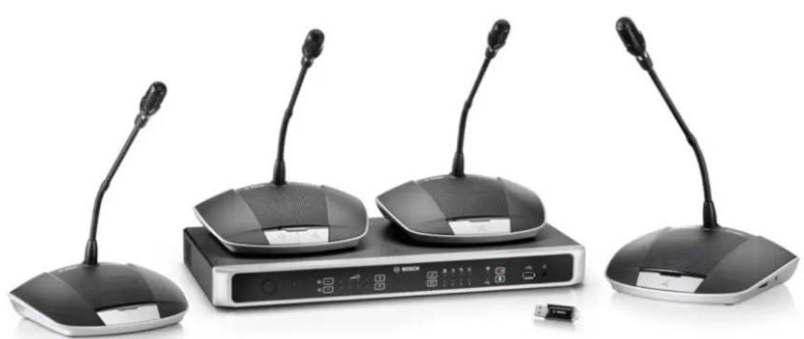
USER MANUAL CCSD-DS BOSCH
Digital Discussion System
CCS 1000 D
natural_image
Black and white photo of a Bosch desktop computer setup with four speakers and a central device (no visible text or symbols)en
Operation manual
Table of contents
| 1 | Safety 5 | |
| 2 | About this manual 6 | |
| 2.1 Manual purpose 6 | ||
| 2.2 Digital document 6 | ||
| 2.3 Intended audience 6 | ||
| 2.4 Alerts and notice signs 6 | ||
| 2.5 Copyright and disclaimer 6 | ||
| 2.6 Document history 7 | ||
| 3 | System overview 8 | |
| 3.1 CCSD-CU(RD) Control Unit 10 | ||
| 3.2 Control Unit with MP3 recording and DAFS 10 | ||
| 3.3 Discussion Device | 11 | |
| 3.4 CCSD-EXU Extension Unit | 11 | |
| 3.5 GUI languages | 11 | |
| 4 | Planning | 12 |
| 4.1 Unpacking | 12 | |
| 4.2 Delivered with products | 12 | |
| 4.2.1 | CCSD-CU Control Unit or CCSD-CURD Control Unit | 12 |
| 4.2.2 | CCSD-Dx Discussion Device | 12 |
| 4.2.3 | CCSD-EXU Extension Unit | 12 |
| 4.3 Additional components | 14 | |
| 4.4 Making custom extension cables | 16 | |
| 4.5 Setup options and limits | 17 | |
| 4.5.1 | Small/medium sized system (max. 80 Discussion Devices) | 17 |
| 4.5.2 | Large system (max. 245 Discussion Devices) | 18 |
| 4.5.3 | Extension cables | 20 |
| 5 | Installation | 23 |
| 5.1 Install Unit(s) | 23 | |
| 6 | Connections | 24 |
| 6.1 Connect system components | 24 | |
| 6.2 Control Unit connections | 26 | |
| 6.3 Discussion Device connections | 28 | |
| 6.4 Extension Unit connections | 29 | |
| 7 | Configuration | 30 |
| 7.1 Control Unit | 30 | |
| 7.1.1 | Discussion modes | 33 |
| 7.1.2 | Key combinations | 34 |
| 7.2 Extension Unit | 35 | |
| 7.3 Discussion Device | 36 | |
| 7.3.1 | Configure Discussion Device | 36 |
| 7.3.2 | Initialize Discussion Device | 36 |
| 7.3.3 | Erase address | 37 |
| 7.4 Web browser interface | 38 | |
| 7.4.1 | First use configuration | 38 |
| 7.4.2 | Login | 39 |
| 7.4.3 | Manage discussion | 43 |
| 7.4.4 | Prepare discussion | 44 |
| 7.4.5 | Manage recorder | 45 |
4 en | Table of contents Digital Discussion System
7.4.6 System settings 46
7.4.7 Power 52
7.4.8 Logging 52
7.4.9 System info 52
7.4.10 Logout 52
7.5 RESTful Application Program Interface (API) 53
8 Operation 54
8.1 Recording and playing back discussion 54
8.2 Using the microphone button 56
8.3 Using the priority button 57
8.4 Adjusting headphones volume 57
9 Troubleshooting 58
9.1 Troubleshooting table 58
10 Maintenance 62
10.1 Cleaning 62
10.2 Inspect components 62
10.3 Storage 62
11 Technical data 63
11.1 Control Unit 63
11.2 Discussion Device 64
11.3 Extension Unit 66
11.4 Safety compliance 67
11.4.1 Control Units 67
11.4.2 Discussion Devices 67
11.4.3 Extension Unit 67
1 Safety
Prior to installing or operating products, always read the Important Safety Instructions which are available as a separate multilingual document: Important Safety Instructions (Safety_ML). These instructions are supplied together with all equipment that can be connected to the mains supply.
Old electrical and electronic appliances
Electrical or electronic devices that are no longer serviceable must be collected separately and sent for environmentally compatible recycling (in accordance with the European Waste Electrical and Electronic Equipment Directive).
To dispose of old electrical or electronic devices, you should use the return and collection systems put in place in the country concerned.
Class A Notice for FCC and ICES 003
applies to U.S.A. and Canadian models only

Business Equipment
For commercial or professional use
This equipment has been tested and found to comply with the limits for a Class A digital device, pursuant to Part 15 of the FCC and Canadian ICES-003 requirements. These limits are designed to provide reasonable protection against harmful interference when the equipment is operated in a commercial environment. This equipment generates, uses, and can radiate radio frequency energy and, if not installed and used in accordance with the instruction manual, may cause harmful interference to radio communications. Operation of this equipment in residential area is likely to cause harmful interference in which case the user will be required to correct the interference at their own expense. Intentional or unintentional changes or modifications not expressly approved by the party responsible for compliance shall not be made. Any such changes or modifications may void the user's authority to operate the equipment.
2 About this manual
- Please read this manual carefully before installing and operating any of the products of the CCS 1000 D Digital Discussion System.
- Retain all documentation supplied with the products for future reference.
2.1 Manual purpose
This manual provides information required for installing, configuring, operating and maintaining the products of the CCS 1000 D Digital Discussion System. For documentation updates, refer to the product related information at: www.boschsecurity.com
2.2 Digital document
This manual is available as a digital document in the Adobe Portable Document Format (PDF). Refer to the product related information at: www.boschsecurity.com.
2.3 Intended audience
This manual is intended for installers, technicians and users of a CCS 1000 D Digital Discussion System.
2.4 Alerts and notice signs
Four types of signs can be used in this manual. The type is closely related to the effect that may be caused if it is not observed. These signs - from least severe effect to most severe effect - are:

Notice!
Containing additional information. Usually, not observing a ‘notice’ does not result in damage to the equipment or personal injuries.

Caution!
The equipment or the property can be damaged, or persons can be lightly injured if the alert is not observed.

Warning!
The equipment or the property can be seriously damaged, or persons can be severely injured if the alert is not observed.

Danger!
Not observing the alert can lead to severe injuries or death.
2.5 Copyright and disclaimer
All rights reserved. No part of this document may be reproduced or transmitted in any form by any means, electronic, mechanical, photocopying, recording, or otherwise, without the prior written permission of the publisher. For information on getting permission for reprints and excerpts, contact Bosch Security Systems B.V..
The content and illustrations are subject to change without prior notice.
2.6 Document history
| Release date | Documentation version Reason | |
| 2014.09 V1.0 1 | ^st edition. | |
| 2014.10 V1.1 | Cover photo and sections: | 2.6, 3, 4, 4.3, 4.5, 6, 6.1,6.2, 7, 7.1, 7.3, 7.3.1 (incl. illustration), 7.3.3, 7.3.4,7.3.5 (incl. illustration), 7.3.6, 7.3.8 adapted. |
| 2016.05 V2.0 | New sections added: 3.4, | 4.2.1, 4.2.2, 4.2.3, 4.5.1,4.5.2, 4.5.3, 6.4, 7.1.2, 7.2, 7.3.2, 7.3.3, 7.4.1, 7.5,11.3Sections updated: 2.6, 3, 6.1, 6.2, 7.4.2, 7.4.4, 7.4.6,8.1, 9.1 |
| 2018.08 V2.1 | Section updated: 7.4.6 | |
| 2020.05 V2.2 | Section added: | -GUI languagesSections updated:-Login: added information about first time login.-System info: completed with additionalavailable information about OSS license terms.-Troubleshooting table: updated table withinformation about how to handle a largeamount of API calls |
3 System overview
flowchart
graph TD
    A["8"] --> B["HD-SDI"]
    B --> C["12"]
    B --> D["13"]
    B --> E["7"]
    B --> F["5"]
    B --> G["5"]
    B --> H["5"]
    B --> I["5"]
    B --> J["9"]
    K["11"] --> L["10"]
    M["11"] --> N["11"]
    O["1"] --> P["4"]
    P --> Q["4"]
    R["6"] --> S["Computer"]
    T["3"] --> U["Microphone 2"]
    V["2"] --> W["Microphone 3"]
    X["1"] --> Y["Microphone 4"]
    Z["10"] --> AA["Smartphone"]
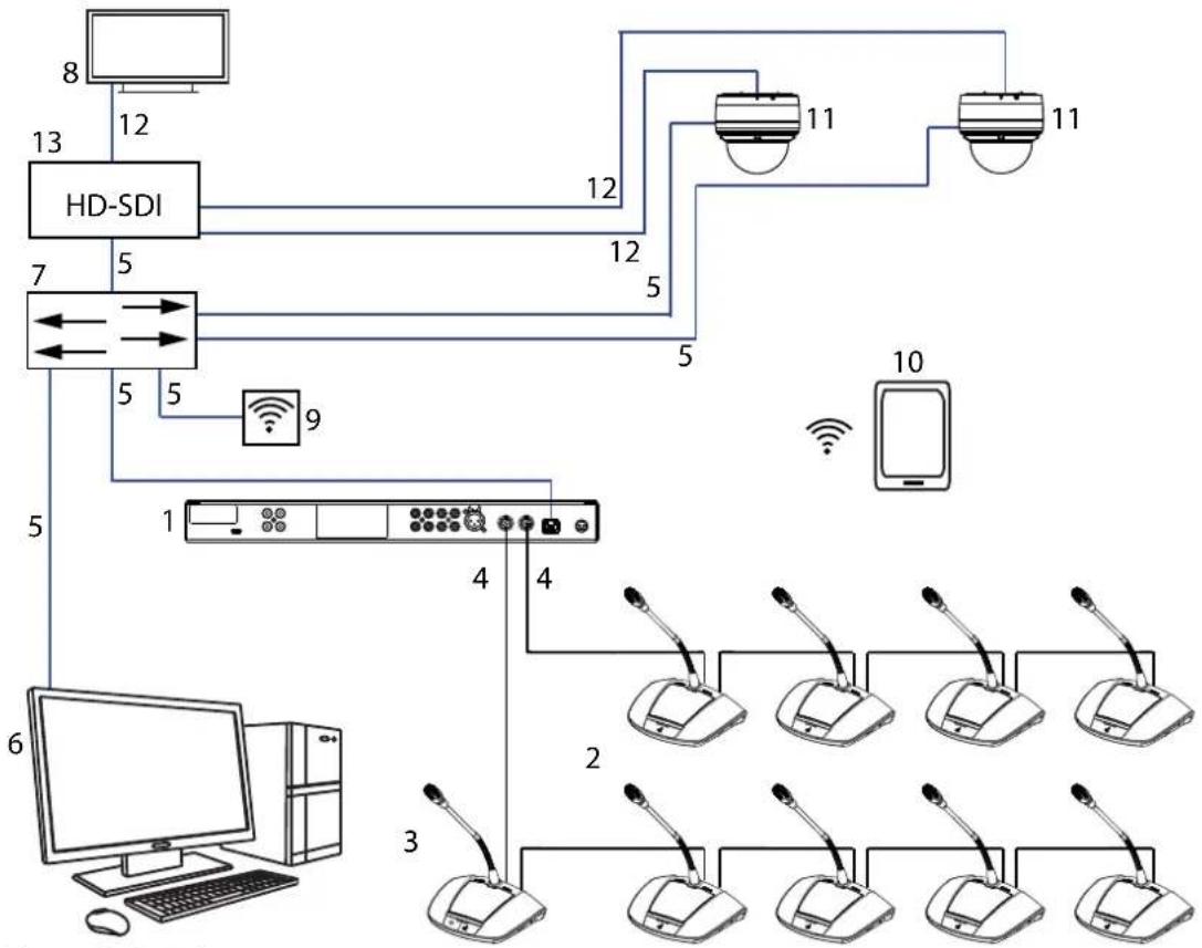
Figure 3.1: Typical system setup
The CCS 1000 D Digital Discussion System is a hot plug-and-play conferencing system that is ideally suited for small to medium-sized meeting areas, such as town halls, local business centers, and courtrooms. The main components of the discussion system are:
- Control Unit: there are two types of control unit: the CCSD-CU and the CCSD-CURD. Their functions and differences are described in CCSD-CU(RD) Control Unit, page 10.
- Discussion Devices (CCSD-Dx), which can be configured as participant devices (2) or a chairperson's device (3).
- Chairperson's device (CCSD-Dx).
- Discussion Device cable (and extension cables as required): connects the Discussion Devices, Control Unit(s), and optional Extension Unit(s) in a daisy-chain configuration.
- Ethernet cable: the Ethernet port is used to connect the laptop or PC, IP camera's, and other equipment solely used to operate the CCS 1000 D Digital Discussion System.
- PC/Laptop: can be used temporary to upgrade the system, or to manage discussions, prepare discussions, and configure the system.
- Ethernet switch: routes the system data via Ethernet.
- Display: can be used to show the speaking participant.
- Wireless access point/router: used in combination with a wireless tablet device.
- Tablet device: can be used to manage discussions, prepare discussions, and configure the system.
- HD Conference Dome: captures the image of a speaking participant.
- Coax cable: transports the video signal between the camera and the HD-SDI (13).
- HD-SDI: is used to connect to the display (8) and to the Ethernet network switch (7). TV-One CORIOmatrix mini and the Kramer MV-6 are supported.
3.1 CCSD-CU(RD) Control Unit

Figure 3.2: CCSD-CU

Figure 3.3: CCSD-CURD
The Control Unit is the central component of the CCS 1000 D Digital Discussion System. Its main purpose is to:
– provide an interface for connecting Discussion Devices and peripheral equipment.
- supply DC power to Discussion Devices.
– monitor and control the CCS 1000 D Digital Discussion System.
Touch-buttons and LED indicators on the front panel are used for configuring and operating. The Control Unit has a built-in web browser interface, which can be accessed with a tablet, laptop, or PC. The web browser interface can be used to view and manage basic and advanced system configuration, such as microphone management and digital recording options. Configuration changes made at the Control Unit are automatically updated in the web browser interface and vice-versa.
3.2 Control Unit with MP3 recording and DAFS

Figure 3.4: CCSD-CURD
The CCSD-CURD has the following additional features:
- Built-in MP3 recorder with internal memory and USB recording.
- Built-in Digital Acoustic Feedback Suppression (DAFS).
- Built-in loudspeaker and headphone socket with volume control for listening to the 'floor language' or recordings.
- Additional RCA outputs for individual microphone recording, e.g. for recording individual speakers in a courtroom.
3.3 Discussion Device
natural_image
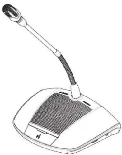
Line drawing of a desktop microphone with a curved neck and ventilation grille (no text or symbols)Figure 3.5: CCSD-Dx
The device allows a participant to take part in a discussion by speaking into the microphone and listening to proceedings through the built-in loudspeaker or (optional) headphones. It has the following main features:
- Microphone button for activating and deactivating the microphone. - LED indicator above the microphone button and a light-ring indicator in head of the microphone.
- Rotary thumbwheel on the side of the device for adjusting the volume of the headphones. A device can be configured as either a 'participant device' or a 'chairperson device', which enables a user to function as the chairperson at a meeting. See Configure Discussion Device, page 36.
3.4 CCSD-EXU Extension Unit

Figure 3.6: CCSD-EXU
The Extension Unit is used in combination with a Control Unit (CCSD-CU or CCSD-CURD) to supply additional power to the CCS 1000 D Digital Discussion System.
One or more Extension Units can be used to expand the CCS 1000 D Digital Discussion System up to 245 Discussion Devices. A single Extension Unit can provide power for up to 85 additional Discussion Devices (CCSD-DS or CCSD-DL).
The Extension Unit is switched on and off automatically with the Control Unit.
3.5 GUI languages
The CCS 1000D Digital Discussion System has the following GUI languages:
| ar cs de | en el es | fi fr | hu id it | ja ko | nl pl pt | pt- | BR | ru th tr vi zh- | CN | zh-TW | |||||||||
| Web browser | • | • | • | • | • | • | • | • | • | • | • | • | • | • | • | • | • | • | • |
4 Planning
Before using the CCS 1000 D Digital Discussion System, read this section to make sure you have all components for connecting and operating the system. This section also includes important information on the number of Discussion Devices that can be connected to the system. See Setup options and limits, page 17.
4.1 Unpacking
This equipment should be unpacked and handled with care. If an item appears to be damaged, notify the shipper immediately. If any items are missing, notify your Bosch representative. The original packaging is the safest container in which to transport products and can be used to return products for service if necessary.
4.2 Delivered with products
Make sure the following items are delivered with your products:
4.2.1 CCSD-CU Control Unit or CCSD-CURD Control Unit
| Quantity Component | |
| 1 CCSD-CU or CCSD-CURD | |
| 1 Mains power cord | |
| 1 24 VDC power supply | |
| 1 Micro USB cable | |
| 2 Sets of chairperson's buttons for a Discussion Device | |
| 1 Exchange tool for buttons | |
| 1 Set of feet for table top use | |
| 1 Set of 19” 1U mounting brackets | |
| 1 Safety instructions | |
| 1 Installation note | |
| 1 DVD with operation manual and supporting tools | |
4.2.2 CCSD-Dx Discussion Device
Quantity Component
1 CCSD-DS or CCSD-DL
1 Quick Installation Guide
4.2.3 CCSD-EXU Extension Unit
Quantity Component
1 CCSD-EXU
1 Mains power cord
1 24 VDC power supply
1 Set of feet for table top use
1 Set of 19" 1U mounting brackets
1 Safety instructions
1 Quick Installation Guide
4.3 Additional components
The following additional components can be used with the CCS 1000 D Digital Discussion System, as required:
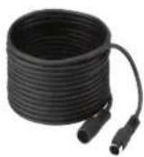
LBB 4116 Series Extension Cables – These standard length extension cables can be connected to components in the daisy-chain. If you want to add one or more extension cables to the system cabling, make sure you follow the guidelines in Setup options and limits, page 17.
| Type number Cable length | |
| LBB 4116/02 2 m (6.6 ft) | |
| LBB 4116/05 5 m (16.0 ft) | |
| LBB 4116/10 10 m (33.0 ft) | |
| LBB 4116/15 15 m (49.2 ft) | |
| LBB 4116/20 20 m (66.0 ft) | |
| LBB 4116/25 25 m (82.0 ft) |
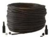
LBB 4116/00 Installation Cable 100 m – This roll of cable and LBB 4119 connectors can be used to make custom length extension cables. See Making custom extension cables, page 16.
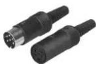
LBB 4119 Connectors (25 pairs) – Pairs of connectors for terminating extension cables made from the LBB 4116/00 roll of cable.
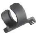
DCN-DISCLM Cable Clamps (25 pcs) – This cable clamp can be used to secure the connector of a Discussion Device to the next Discussion Device in the daisy chain.
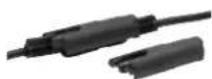
LBB 4117/00 Cable Locking Clamps (25 pcs) – This cable locking clamp can be used to lock the connectors of extension cables. One cabling locking clamp is required for each male/female connector.
USB memory stick (CCSD-CURD only) – A correctly formatted USB memory stick is required if you want to record discussions directly to an external device. Refer to the following information:
- Preferred type: Sandisk.
- Maximum size: 128 GB.
- Formatting: The USB memory stick must be formatted to the FAT32 file system. If required, the USB memory stick can be formatted using:
- the recommend formatting tool on the DVD supplied with the Control Unit. This tool can also be downloaded from the relevant product page on: www.boschsecurity.com - the Windows default formatting tool. This tool can only format USB memory sticks up to 32 GB to the FAT32 file system.
- Partition: Device with single FAT32 partition.
- Partitioning scheme: Must be MBR (GPT is not supported).
Note: The partitioning scheme can also be changed with the formatting tool.
USB cable with micro USB connector - A USB cable with a micro USB connector is required if you want to transfer the internal memory (recordings) to a PC.
RJ45 Ethernet cable - An RJ45 Ethernet cable is required if you want to connect a laptop or PC to the control unit for running the web browser interface and connecting system cameras.
RCA cables - RCA cables are required if you want to connect optional audio equipment to the Control Unit, such as a sound reinforcement system.
XLR cable - An XLR cable is required if you want to connect an external microphone to the Control Unit.
Wireless Access Point (WAP) - A commercially available wireless access point or router is required if you want to connect equipment with a WiFi connection to the system.
4.4 Making custom extension cables
Custom extension cables can be made from the LBB 4116/00 DCN-NG installation cable 100m and LBB 4119/00 DCN-NG connectors (25 pairs). Refer to the following figures and table:
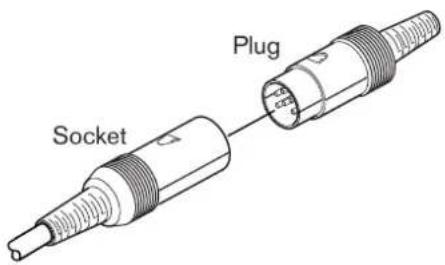
Figure 4.1: Extension cable plug and socket
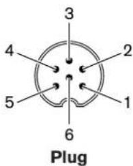
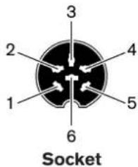
Figure 4.2: Plug and socket pin numbers
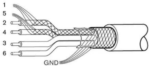
Figure 4.3: Extension cable connections
| Pin Signal Color | ||
| 1 Downlink GND --- | ||
| 2 Downlink data Green | ||
| 3 +24 V(DC) Brown | ||
| 4 Uplink data White | ||
| 5 Uplink GND --- | ||
| 6 +24 V(DC) Blue |
Tab. 4.1: Extension cable connections
4.5 Setup options and limits
This section describes the setup options and limits for the CCS 1000 D Digital Discussion System. The following example system setups are described:
- A small/medium sized system that has a Control Unit, and a maximum of 80 Discussion Devices. See Small/medium sized system (max. 80 Discussion Devices), page 17.
- A large system that has a Control Unit, one or more Extension Units, and a maximum of 245 Discussion Devices. See Large system (max. 245 Discussion Devices), page 18.
- A system that has extension cables longer than 20 m (66.0 ft) connected to a trunk or tap-off. See Extension cables, page 20. Note: Due to power loss, extension cables longer than 20 m (66.0 ft) have a direct effect on the number of Discussion Devices that can be connected to a trunk/tap-off.
4.5.1 Small/medium sized system (max. 80 Discussion Devices)
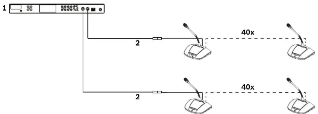
A small/medium sized system has one Control Unit and a maximum of 80 Discussion Devices. The following limits are applicable in this situation:
- Limit 1: A maximum of 40 Discussion Devices can be daisy-chained to each trunk of the Control Unit.
- Limit 2: If an extension cable longer than 20m (66.0 ft) is added to a trunk, the number of Discussion Devices that can be added to that trunk is reduced. Refer to the table in Extension cables, page 20.
- Limit 3: The maximum cable length for a trunk is 100m (328.0 ft). This includes all extension cables (including the first 20m (66.0 ft) of extension cable) + the Discussion Device cables of 2m (6.6 ft) per device.
The following figure shows the maximum of 40 Discussion Devices connected to each trunk of the Control Unit: 40 + 40 = 80 Discussion Devices.
flowchart
graph TD
    A["1"] --> B["2"]
    B --> C["40x"]
    C --> D["2"]
    D --> E["40x"]
    E --> F["2"]
    style A fill:#f9f,stroke:#333
    style B fill:#ccf,stroke:#333
    style C fill:#cfc,stroke:#333
    style D fill:#fcc,stroke:#333
    style E fill:#cff,stroke:#333
    style F fill:#ffc,stroke:#333
Figure 4.4: Example setup for a small/medium sized system (max. 80 discussion devices)
- Control Unit
- Extension cable 20 m (66.0 ft) long connected to each trunk of the Control Unit
4.5.2 Large system (max. 245 Discussion Devices)
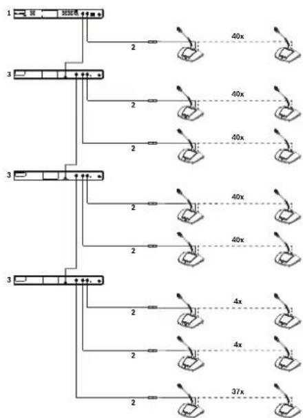
A system can be extended (by more than 80 Discussion Devices) by adding one or more Extension Units to a trunk of the Control Unit.
- Limit 1: A maximum of 40 components can be daisy-chained to a trunk of the Control Unit.
Note: A component can be a Discussion Device or an Extension Unit.
- Limit 2: A maximum of 40 Discussion Devices can be daisy-chained to each tap-off of an Extension Unit.
- Limit 3: A maximum of 85 Discussion Devices can be connected to each Extension Unit.
- Limit 4: A maximum of 245 Discussion Devices can be connected to the system.
- Limit 5: If an extension cable longer than 20m (66.0 ft) is added to a trunk/tap-off, the number of Discussion Devices that can be added to that trunk/tap-off is reduced. Refer to the table in Extension cables, page 20.
- Limit 6: The maximum cable length for a trunk/tap-off is 100m (328.0 ft). This includes all extension cables (including the first 20m (66.0 ft) of extension cable) + the Discussion Device cables of 2m (6.6 ft) per device. + the Extension Unit cables.
The following figure shows:
- the maximum of 40 components connected to the trunk: 3 Extension Units + 37 Discussion Devices = 40 components.
- the maximum number of Discussion Devices (245) connected to the system.
flowchart
graph TD
    A["DC"] --> B["1"]
    A --> C["2"]
    A --> D["3"]
    B --> E["DC"]
    C --> F["3"]
    D --> G["3"]
    E --> H["40x"]
    F --> I["40x"]
    G --> J["40x"]
    H --> K["40x"]
    I --> L["40x"]
    J --> M["40x"]
    K --> N["40x"]
    L --> O["40x"]
    M --> P["40x"]
    N --> Q["40x"]
    O --> R["40x"]
    P --> S["40x"]
    Q --> T["40x"]
    R --> U["40x"]
    S --> V["40x"]
    T --> W["40x"]
    U --> X["40x"]
    V --> Y["40x"]
    W --> Z["40x"]
    X --> AA["40x"]
    Y --> AB["40x"]
    Z --> AC["37x"]
Figure 4.5: Example setup for a large system (max. 245 Discussion Devices)
- Control Unit
- Extension cable 20 m (66.0 ft) long
- Extension Unit
4.5.3 Extension cables
Adding an extension cable longer than 20 m (66.0 ft) to a trunk/tap-off has a direct effect on the available power for the components connected in the daisy chain. A component can be a Discussion Device or an Extension Unit.
Use the following table to determine the total number of components that can be connected to a trunk/tap-off when one or more extension cables are connected to that trunk/tap-off.
- Limit 1: The maximum cable length for a trunk/tap-off is 100m (328.0 ft). This includes all extension cables (including the first 20m (66.0 ft) of extension cable) + the Discussion Device cables of 2m (6.6 ft) per device. + the Extension Unit cables.
| Total length of extension cable(s) per trunk/ tap-off | Maximum number of components per trunk/ tap-off |
| 0 m to 20 m 40 | |
| 20 m to 22 m 39 | |
| 22 m to 24 m 38 | |
| 24 m to 26 m 37 | |
| 26 m to 28 m 36 | |
| 28 m to 30 m 35 | |
| 30 m to 32 m 34 | |
| 32 m to 34 m 33 | |
| 34 m to 36 m 32 | |
| 36 m to 38 m 31 | |
| 38 m to 40 m 30 | |
| 40 m to 42 m 29 | |
| 42 m to 44 m 28 | |
| 44 m to 46 m 27 | |
| 46 m to 48 m 26 | |
| 48 m to 50 m 25 | |
| 50 m to 52 m 24 | |
| 52 m to 54 m 23 | |
| 54 m to 56 m 22 | |
| 56 m to 58 m 21 | |
| 58 m to 60 m 20 | |
| 60 m to 62 m 19 | |
| 62 m to 64 m 18 | |
| 64 m to 66 m 17 | |
| 66 m to 68 m 16 | |
| 68 m to 70 m 15 | |
| 70 m to 72 m 14 | |
| 72 m to 74 m 13 | |
| 74 m to 76 m 12 | |
| 76 m to 78 m 11 | |
| 78 m to 80 m 10 | |
| 80 m to 82 m 9 | |
| 82 m to 84 m 8 | |
| 84 m to 86 m 7 | |
| 86 m to 88 m 6 | |
| 88 m to 90 m 5 |
Tab. 4.2: Max. number of components per trunk/tap-off depending on total length of extension cable(s)
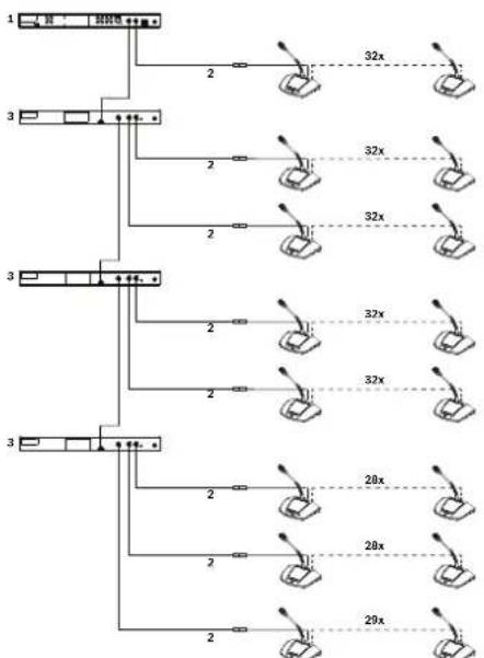
The following figure shows:
- the maximum number of Discussion Devices (245) connected to the system.
- an extension cable of 35 m (115.0 ft) connected to the trunk and each tap-off.
In this example, the trunk can only have 32 components in total, because of the 35 m (115.0 ft) of extension cable connected to the trunk (refer to the previous table): 3 Extension Units + 29 Discussion Devices = 32 components.
flowchart
graph TD
    A["1"] --> B["2"]
    B --> C["32x"]
    D["3"] --> E["2"]
    E --> F["32x"]
    G["3"] --> H["2"]
    H --> I["32x"]
    J["3"] --> K["2"]
    K --> L["32x"]
    M["3"] --> N["2"]
    N --> O["32x"]
    P["28x"] --> Q["28x"]
    R["29x"] --> S["29x"]
Figure 4.6: Example setup for a large system with 35 m of extension cable connected to the trunk and each tap-off
- Control Unit
- Extension cable 35 m (115.0 ft) long
- Extension Unit
5 Installation
This section describes the installation requirements and options for the Control Unit and Extension Unit.
5.1 Install Unit(s)
The Control Unit and Extension Unit can be placed on a table top or installed in a 19" rack:
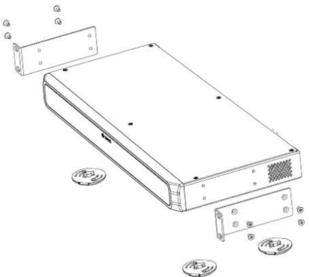
natural_image
Technical line drawing of a computer chassis with exploded view and component labels (no text or symbols)Figure 5.1: 19" rack installation
If you decide to install the unit(s) in a 19" rack:
- do not attach the feet to the bottom of the unit(s).
- make sure the rack is of suitable quality to support the weight of the unit(s).
- use the supplied 19" rack mounting brackets and screws to attach the unit(s) to the rack. Take care when lifting and attaching the unit(s).
- make sure the ventilation holes on the side of the unit(s) are unobstructed.
- make sure the temperature inside the rack cannot exceed +45 °C.
If you want to use the unit(s) on a table top:
- click the four feet into place at the bottom of the unit(s).
- keep the mounting brackets and screws in case you want to install the unit(s) in a rack in the future.
6 Connections
This section describes the connections of:
- the Control Unit
- the Discussion Device
- the Extension Unit
6.1 Connect system components
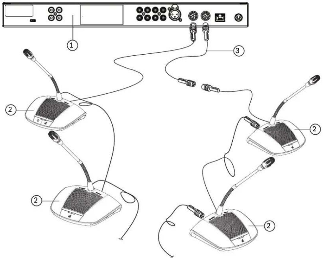
Figure 6.1: Connecting Discussion Devices
For detailed information on the connections of the CCS 1000 D Digital Discussion System, refer to:
- Control Unit connections, page 26
-
Extension Unit connections, page 29
– Discussion Device connections, page 28 -
Connect the Discussion Devices (2) in a daisy-chain configuration, using extension cables (3) where required, to the 'Trunk' connectors at the rear of the Control Unit (1) and optional Extension Units.
Note: The above figure only shows a small system with a Control Unit. For the maximum number of Discussion Devices and Extension Units that can be connected to the system, including extension cables, refer to Setup options and limits, page 17.
- Secure the system cables with cable clamps and cable locking clamps, as required.
-
If you want to use the web browser interface or system cameras with the CCS 1000 D Digital Discussion System, connect an RJ45 Ethernet cable to the 'Network' connector at the rear of the Control Unit.
-
Connect the other end of the Ethernet cable to an Ethernet switch, laptop, or PC.
- Use RCA cables to connect audio equipment to the 'Audio In' and 'Audio Out' connectors at the rear of the Control Unit, as required. Inputs and outputs are not galvanic separated. If galvanic separation is required (e.g. to avoid hum), it must be provided externally.
- Connect the supplied 24 VDC power supply connector to the 'power' connector at the rear of the Control Unit.
- Connect the mains plug of the 24 VDC power supply to a mains supply. The system will automatically switch on at the moment the mains supply is connected. This allows the system to recover from a power failure.

Caution!
Non-approved power supplies can damage the equipment. Only use the original Bosch supplied 24 VDC power supply.
6.2 Control Unit connections
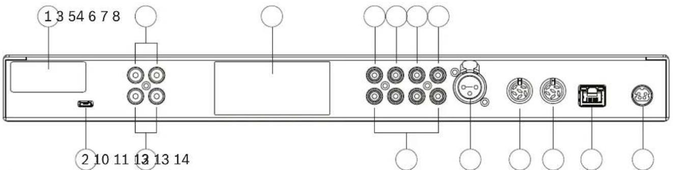
Figure 6.2: CCSD-CURDrear view
The CCSD-CURD has additional connections as indicated in the following table:
| Number | Item | Description |
| 1 | FCC label | Label showing FCC Declaration of Conformity. |
| 2 | USB(CCSD-CURD only) | Micro USB connector for transferring the internal memory (recordings) to a PC. The micro USB connector cannot be used to directly record discussions to a USB device. The larger USB connector on the front panel of the unit should be used for that purpose.Note: Recordings cannot be saved to the internal memory or a USB memory stick when the micro USB connector is in use. Do not record discussions during the transfer of files! |
| 3 | RCA ‘Audio Out’(CCSD-CURD only) | 4 x audio output connectors for individual microphone recording, e.g. for recording individual speakers in a courtroom. |
| 4 | Product label | Label showing information on the product, such as: product type, serial number, technical data, and CE mark. |
| 5 | RCA ‘Audio Out (1)’ | Audio output connector for connecting a PA or sound reinforcement system to the discussion system. Enables proceedings to be transmitted to an audience in the same room or an adjacent room. |
| 6 | RCA ‘Audio Out (2)’ | Used with RCA ‘Audio In (2)’.Audio output connector for either:- ‘Recorder’ for connecting an external recorder.- ‘Insertion’ for connecting an external audio processor.- ‘Telephone/mix minus’ for allowing a remote participant to join a discussion via a telephone/video connection.- ‘Participant loudspeaker’ for distributing the participant loudspeaker signal to a sound reinforcement system.Note: Only one piece of audio equipment can be connected to ‘Audio Out (2)’ at a time. The output can be configured by selecting the required option in the web browser interface. See Audio under the heading System settings, page 46. |
| 7 | RCA ‘Audio In (1)’ | Audio input connector for ‘Floor’, i.e. for connecting an external audio source, such as a CD or DVD player. |
| 8 | RCA ‘Audio In (2)’ | Used with RCA ‘Audio Out (2)’.Audio input connector for either: |
2020.05 | V2.2 | Operation manual Bosch Security B.V.
| Number | Item Description | |
| -‘Insertion’ for connecting an external audio processor.-‘Telephone/mix minus’ for allowing a remote participant to join a discussion via a telephone/video connection.This audio input routes an external audio signal into the system that is routed to the Discussion Devices loudspeakers. In the web browser interface, the mode setting of I/O 2 depends on whether this input is configured as insertion or mixed minus.-Note: Only one piece of audio equipment can be connected to ‘Audio Out (2)’ at a time. The output can be configured by selecting the required option in the web browser interface. See Audio under the heading System settings, page 46. | ||
| 9 RCA Audio Additional audio input/output | put connectors that have the same functionas items 5 through 8. These additional audio connectors can be used with their corresponding audio connector to increase the strength of the audio signal. | |
| 10 Microphone 3-pole XLR female (ambient) | microphone connector with phantom(P24) supply for connecting an external microphone. This input is shared with Audio In (1) and has to be enabled in the web browser interface. Once enabled Audio In (1) cannot be used. | |
| 11 Trunk | (1) 6-pole circular female connector for connecting Discussion Devices. | |
| 12 Trunk | (2) 6-pole circular female connector for connecting Discussion Devices. | |
| 13 Network RJ45 Ethernet socket for connecting a network cable. The Ethernet port is intended to connect a laptop or PC, IP camera's and other equipment which is solely used to operate the CCS 1000 D system. | ||
| 14 Power | 24V 6A 4-pole circular female connector for connecting the 24 VDC power supply. | |

Caution!
Non-approved power supplies can damage the equipment. Only use the original Bosch supplied 24 VDC power supply.

Notice!
The audio inputs/outputs are mono but the audio connectors allow for the connection of stereo RCA cables.
Refer to
- System settings, page 46
6.3 Discussion Device connections
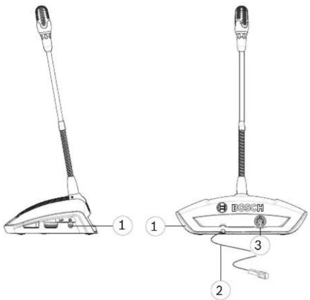
Figure 6.3: Rear and side view
| Number Item Description | |
| 1 Headphone 3.5 mm (0.14 in) stereo headphone socket (on side of unit). | |
| 2 Trunk connection 2 m (78.7 in) cable with 6-pole circular male connector and cable lock for connecting to the previous component in the daisy-chain. This can be:– the Control Unit,– another Discussion Device,– an Extension Unit, or– an extension cable. | |
| 3 Trunk connection 6-pole circular female connector for connecting the next component in the daisy-chain. This can be:– another Discussion Device,– an Extension Unit, or– an extension cable. | |
6.4 Extension Unit connections

Figure 6.4: CCSD-EXU rear view
| Number | Item Description | |
| 1 FCC label | Label showing the FCC Declaration of Conformity. | |
| 2 Product | label Label showing information on the product, such as: product type, serial number, technical data, and CE mark. | |
| 3 | Trunk cable with connector | 2 m (78.7 in) cable with 6-pole circular male connector and cable lock for connecting the Extension Unit to the previous component in the daisy-chain. This can be:- the Control Unit,- another Extension Unit,- an extension cable, or- a Discussion Device. |
| 4 Trunk connection | 6-pole circular female connector for connecting the next component in the daisy-chain. This can be:- another Extension Unit,- an extension cable, or- a Discussion Device. | |
| 5 Tap-off | connection 6-pole circular female connector for connecting Discussion Devices. | |
| 6 Tap-off | connection 6-pole circular female connector for connecting Discussion Devices . | |
| 7 Power | 24V 6A 4-pole circular female connector for connecting the 24 VDC power supply. |

Caution!
Non-approved power supplies can damage the equipment. Only use the original Bosch supplied 24 VDC power supply.
7 Configuration
To configure the CCS 1000 D Digital Discussion System you can use:
- the touch buttons on the front of the control unit, or
- the web browser interface. For more information, see Web browser interface, page 38.
The control unit can be used to quickly view and change basic settings. The advantages of using the web browser interface to configure the system are:
– additional options and settings are available.
- settings can be easily managed remotely.

Notice!
Changes made on the control unit are automatically updated in the web browser interface and vice-versa.
7.1 Control Unit
- After connecting power, the Control Unit automatically powers up. The power on/off LED turns green, and the other LEDs on the front panel are alternatively lit to indicate that the system is initializing. The system is ready for use when the LEDs are constantly lit.
- Press the touch buttons on the front panel to set basic system settings. The LED indicators will change to indicate the setting. Refer to the following figure and table for more information on the settings:
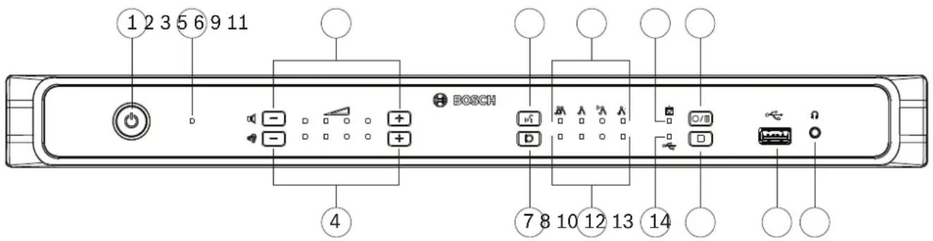
Figure 7.1: CCSD-CURD front view
The CCSD-CURD has additional features as indicated in the following table:
| Number | Item | Description |
| 1 | Power on/off button | On/off push button for 24 VDC:Power on: Short press.Power off: Long press.Note: When the system is powered off, the ‘waiting list’ and ‘speakers list’ are automatically saved and will be available again when the system is powered on. |
| 2 | Power on/off LED | LED indicator for showing the on/off status.- Red: Power off.- Green: Power on or standby.Note: When the Control Unit is in standby, the Discussion Devices volume control LED (3) flashes slowly. |
| Number | Item Description | |
| 3 Buttons | and LED indicators for volume control of Discussion Devices | Plus/minus buttons for setting the volume of all Discussion Devices and Audio Out (1).The LED indicators show the selected volume in four steps of brightness per LED from left to right.Note:Audio Out (2) is not influenced by any setting. |
| 4 Buttons | and LED indicators for volume control of loudspeaker or headphones connected to the CCSD-CURD. | Plus/minus buttons for setting the volume of:- the built-in loudspeaker, or- headphones, if connected.The LED indicators show the selected volume in four steps of brightness per LED from left to right. |
| 5 Discussion-mode button Button for selecting one of the four discussion modes. Used in combination with the discussion-mode LED indicators (6). | ||
| 6 Discussion mode LED indicators | LED indicators for showing the selected discussion mode. The following modes are indicated from left to right:- Open mode- Override mode- Voice activation mode- Push to talk (PTT) modeNote:If all LED indicators are off, ‘open mode’ is selected and ‘auto shift’ in thePrepare discussionpage of the web browser interface is set to off.For detailed information on the discussion modes, seeDiscussion modes, page 33. | |
| 7 Speakers list size Button for selecting the number of microphones that can be activated at the same time. Used in combination with the speakers list size LED indicators (8).A maximum of four microphones can be selected from the Control Unit If the web browser interface is used, a maximum of ten microphones can be selected. | ||
| 8 Speakers list size LED indicators | LED indicators for showing the number of activated (open) microphones.1 to 4 open microphones: the LEDs are individually lit to show the number of open microphones.5 to 10 open microphones: a combination of LEDs are lit to show the number of open microphones; for example, if there are six open microphones, LED numbers 2 and 4 are lit. | |
| 9 Internal recording LED indicator (CCSD-CURD only) | LED indicator for showing the status of internal recordings:- Green continuous: Internal memory selected; ready for recording.- Red continuous: Recording is taking place.- Red flashing once a second: Recording paused.- Red flashing twice a second: 5 minutes of recording left. Three short beeps, from the monitor loudspeaker, will also be sounded to alert the user. | |
| - Red/green flashing: Discussions cannot be recorded to the internal memory (i.e. internal memory is full). A single long beep will also be sounded to alert the user. | ||
| 10 USB recording LED indicator (CCSD-CURD only) | LED indicator for showing the status of USB memory stick recordings:- Green continuous: USB memory stick selected: Ready for recording.- Red continuous: Recording is taking place.- Red flashing once a second: Recording paused.- Red flashing twice a second: 5 minutes of recording left. Three short beeps will also be sounded to alert the user.- Red/green flashing: Discussions cannot be saved to the USB stick (i.e. USB memory stick is full, incorrectly formatted, or damaged). A single long beep will also be sounded to alert the user.Note: The USB recording LED will be automatically selected and deselected when the USB memory stick is inserted and removed from the USB connector at the front of the Control Unit. | |
| 11 Start/pause recording button (CCSD-CURD only) | Button for starting and pausing a recording session. SeeRecording and playing back discussion, page 54. | |
| 12 Stop recording button (CCSD-CURD only) | Button for stopping a recording session. | |
| 13 USB connector (CCSD-CURD only) | USB connector for connecting a USB memory stick.. For information on the USB memory stick requirements, seeAdditional components, page 14. | |
| 14 Headphone socket (CCSD-CURD only) | 3.5 mm (0.14 inch) stereo headphone socket for connecting headphones (for listening to recorded discussions). When headphones are connected, the built-in loudspeaker is muted. | |
7.1.1 Discussion modes
The discussion modes: Open, Override, Voice, and Push To Talk (PTT) can be selected by using:
- The discussion mode button on the front panel of the Control Unit, or
- The web browser interface. In the prepare discussion page, click a discussion mode at the top of the page to select it. The button will be highlighted grey, and the options for that discussion mode will be activated.
88
Open
Participants can issue a request to speak by pressing their microphone button. The request could be granted immediately, placed in a waiting list or ignored. The request to speak of one participant will not remove another participant from the speakers list; the participant must wait their turn. The chairperson's microphone and interruption microphone are not included in the number of speakers/open microphones, so that participants using these microphones do not have to wait to speak. The speakers list and waiting list can be viewed and managed in the web browser interface.
8
Override
Participants can issue a request to speak by pressing their microphone button. The request could be granted immediately or ignored. The request to speak of one participant could remove another participant from the speakers list; the longest open microphone will be closed if needed to comply with the configured maximum number of open microphones. The chairperson's microphone and interruption microphone are not included in the number of speakers/open microphones, so that they cannot be 'overridden' by a participant. The speakers list can be viewed and managed in the web browser interface. The waiting list is not used in this mode.
8
Voice
Participants can issue a request to speak by speaking into their microphone. The request will be granted if the participant speaks loud enough, otherwise the request is ignored. There are no speakers or waiting lists in the web browser interface.
Note: A microphone can be temporarily muted by pressing and holding down the microphone button.
8
Push To Talk (PTT)
Participants can issue a request to speak by pressing their microphone button. The request could be granted immediately or ignored. If the request is granted, the participant has to keep the button pressed in to speak; the microphone is deactivated when the microphone button is released. The request to speak of one participant will not remove another participant from the speakers list; the participant must wait their turn. The chairperson's microphone and interruption microphone are not included in the number of speakers/open microphones, so that participants using these microphones do not have to wait to speak. The speakers list can be (viewed and) managed in the web browser interface. The waiting list is not used in this mode.
7.1.2 Key combinations
Key combinations can be selected on the front panel of the Control Unit to reset or initialize system settings (refer to the following table).
Push and hold in the key combinations for a few seconds until the LEDs on the front panel change status.
| Option Key combinations on Control Unit | |
| De-initialize Discussion DevicesErases the addresses of all Discussion Devices. All LEDs on a Discussion Device go on when the address is erased.Initialize each of the Discussion Devices, as described in Initialize Discussion Device, page 36. |  |
| Reset login detailsResets the following for the web browser interface:- the admin account password.- the network settings.Use this option if you have forgotten the hostname or password. |  |
| Set factory defaultsResets all system settings and values to the factory defaults. |  |

Notice!
When the system is reset to the factory defaults, the latest version of the software that the system was upgraded to will be maintained.
7.2 Extension Unit

Figure 7.2: CCSD-EXU front view
The Extension Unit is switched on and off automatically with the Control Unit.
| Number Item Description | |
| 1 Power on/off LED LED indicator for showing the on/off status- Red: Power off or standby.- Green: Power on. | |
7.3 Discussion Device
This section describes how to configure the device.
7.3.1 Configure Discussion Device
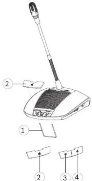
Figure 7.3: Exchanging the buttons
The Discussion Device is delivered as a participant's device. To configure the device as a chairperson's device:
- Unplug the device from the system cabling.
- Use the exchange tool (1) to push the single microphone button (2) from the device as shown (store the single button in a safe place).
- Preposition and then gently press the chairperson's priority button (3) and microphone button (4) into place. Do not use excessive force!
- Set the slide-switch (2) at the base of the device from the participant's setting (0)' to the chairperson's setting (1)'. See figure in Erase address, page 37.
- Reconnect the device to the system cabling. A restart of the system is not necessary. A total of 25 Discussion Devices can be configured as chairperson's devices/interruption microphones.
For example: 22 chairperson's devices + 3 interruption microphones = 25 devices in total.
7.3.2 Initialize Discussion Device
When a Discussion Device is powered on for the first time, it has no address and no association with the Control Unit. To indicate this:
- the light-ring in the head of the microphone is lit red.
- the LED indicator above the microphone button is lit amber.
To initialize/address a Discussion Device:
- Push the microphone button once.
- Wait until all LEDs on the device are off. The device is then correctly initialized.
- If the device does not initialize correctly, erase the address as described in Erase address, page 37, and then push the microphone button to initialize/address the device
Note: The address can also be erased in the web browser interface, by clicking the de-init button on the seat settings page. For more information, see System settings, page 46 > Seats.
7.3.3 Erase address
- Push and immediately release the concealed initialization button (1) at the base of the Discussion Device:
- The light-ring in the head of the microphone is lit red.
- The LED indicator above the microphone button is lit amber.
- Initialize the device as described in Initialize Discussion Device, page 36.
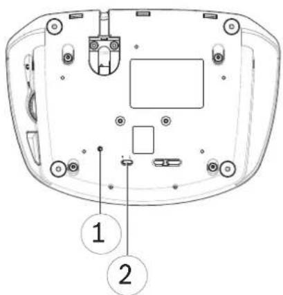
Figure 7.4: Base view
- Concealed initialization button.
- Slide-switch for configuring.
7.4 Web browser interface
This section describes how to configure the web browser interface.
7.4.1 First use configuration
The web browser interface of the CCS 1000 D Digital Discussion System is used to:
- upgrade the system software.
- configure the CCS 1000 D Digital Discussion System.
- prepare and manage discussions.
Web browser
The CCS 1000 D Digital Discussion System is compatible with and optimized for the latest version of these web browsers:
- Internet Explorer
- Safari
- Firefox
- Opera
- Chrome
Preconditions
- All used system components are connected, as described in Connect system components, page 24.
- The Control Unit is connected via the Ethernet network port to your (wireless) network.
- The Control Unit is switched on.
- All Discussion Devices are correctly configured, as described in Configure Discussion Device, page 36.
- A configuration tablet device and/or PC/laptop, including a compatible web browser is switched on.
- On a Windows PC/laptop, make sure:
- Bosch DNS-SD is installed. Bosch DNS-SD is on the DVD supplied with the Control Unit and can be downloaded from the relevant product page on: www.boschsecurity.com
- a dynamic IP address has been assigned to the laptop/PC. If the laptop/PC has a static IP address, the web browser interface will not work correctly.
- On any other device:
- make sure Apple Bonjour is installed. Apple Bonjour can be downloaded from the Apple website. Apple Bonjour is required if you want to enter the (link-local) default web address of the Control Unit.
Note: Apple Bonjour or Bosch DNS-SD are not available for Android.
Create a connection to the web browser interface
- Open your web browser.
- Enter the (link-local) default web address of the Control Unit: http://CCS1000D.local
- The default hostname is: CCS1000D.local
-
Remove the .local for domain servers.
Note: CCS1000D.local is not supported on Android, because Android does not support Bonjour and DNS-SD. -
A login page is displayed.
Log in and update the system software
- Log in to the web browser interface. Refer to Login, page 39.
- Update the system software. Refer to Upgrade in System settings, page 46.
7.4.2 Login
Multiple users can log in to the CCS1000D system at the same time, providing they log in on separate web browsers or separate devices (tablet, laptop or PC).
First time login
Since version 1.7, when logging in for the first time, the user must follow a wizard to configure the system.
- Select the desired language and click Setup device to start the configuration.
- Press the button sequence on the device indicated on the screen. Click the Next button once you complete the sequence correctly to advance to the next screen.
- Click the Change password button if you wish to change the user password.

Notice!
When upgrading from version 1.6 or lower to version 1.7 or higher, the wizard is displayed if no password is set.
Normal login
-
Enter the username and password.
-
The default username for the latest software version is 'admin'.
- the password does not have to be filled in.
Note: if you are upgrading the software from a previous version of which the default username is 'Technician', after the upgrade the username will be set to 'admin'.
-
Select the required language from the dropdown list, and then click login.
-
The default language is the language of the operating system running the browser.
-
if the default language is not available, English is automatically selected.
-
If the login is successful, the homepage is displayed:
CCS 1000 Digital Discussion System









natural_image
Blue horizontal bar with white icons at top, left, and bottom (no text or symbols)Figure 7.5: Homepage (CCSD-CURD)

Notice!
Some web browser interface options may not be available for the CCSD-CU, because this version of the Control Unit does not have DAFS and recording functionality.
Homepage buttons:
| Button Description | Access right | |
 Manage discussion Manage discussion | To manage a discussion. See Manage discussion, page 43. | Manage meeting |
 Prepare discussion Prepare discussion | To prepare a discussion. See Prepare discussion, page 44. | Prepare meeting |
 Manage recorder (CCSD-CURD only) Manage recorder (CCSD-CURD only) | To manage the recorder. See Manage recorder, page 45. | Manage meeting |
 System settings System settings | To configure the system. See System settings, page 46. | Configure or Modify users |
 Power Power | On: Activates the Control Unit. After a few seconds, the system is ready for use.Standby: Sets the Control Unit to ‘standby’ and switches off the devices:- All LEDs on the Discussion Devices go out.- To indicate that the Control Unit is in ‘standby’, the green power on LED on the front panel is lit, and the Discussion Devices volume control LED flashes slowly. All other LEDs are off.- The ‘waiting list’ and ‘speakers list’ are cleared.- Recording is stopped, if active.Cancel: Closes the ‘power’ pop-up window. | Prepare system |
 Logging Logging | Overview and saving of system events. See Logging, page 52. | Configure |
 System info System info | Overview of MAC and IP addresses and software versions of the Control Unit and web browser interface application. See System info, page 52. | Configure |
 Logout Logout | Exits the discussion application and returns you to the login page. See Logout, page 52. | None |
 Home Home | Returns you to the web browser interface homepage. | None |
 Back Back | Returns you to the previous page. None | |
 Start recording(CCSD-CURD only) Start recording(CCSD-CURD only) | Click the ‘start recording’ button to start recording. When recording is started, the ‘pause’ button and ‘stop recording’ button are displayed.Note: The ‘start recording’ button is hidden when the recording memory is full.Note: When an audio file is being played from the Manage recorder page of the web browser interface, a recording can only be started from the front panel of the Control Unit. The ‘start recording’ button is disabled. | Manage meeting |
 Pause recording(CCSD-CURD only) Pause recording(CCSD-CURD only) | Click the ‘pause’ button to pause recording.Manage meeting | |
 Stop recording(CCSD-CURD only) Stop recording(CCSD-CURD only) | Click the ‘stop recording’ button to stop recording. | Manage meeting |
 Master volume Master volume | Opens the master volume control slider. Controls the discussion devices loudspeaker and Control Unit audio output level. | Configure or Manage meeting |
7.4.3 Manage discussion

Preconditions:
- The logged on user must have the access right: Manage meeting.
Manage discussion means:
- View and control the waiting list and speakers list
- Control recording (CCSD-CURD only)
- Control master volume
Click the Manage discussion button on the homepage to open the manage discussion page.
This page shows the discussion list, which has separate lists for waiting participants (left side of page), and speakers (right side of page).
Note: The waiting participants list is only available in the ‘Open’ discussion mode. In the ‘Voice’ activation mode, both the speakers list and the waiting participants list are not available.
- Click the + button to select and add participants to the waiting list or speakers list.
- Click the recycle bin to remove a seat from the waiting list or speakers list.
- Use the shift button, to shift participants from the waiting list or speakers list. If the speakers list is full, the longest speaking participant is removed from the list.
- Click the Stop and remove all button to remove all waiting speakers and speakers from the lists.
The maximum number of seats that can be added to the speakers list can either be set:
– on the Prepare discussion page. See Prepare discussion, page 44, or
– on the Control Unit. See Control Unit, page 30.
Note: The maximum number of seats does not include the chairperson's seat or the Discussion Device configured as an interruption microphone, because the chairperson's microphone and the interruption microphone can always be activated.

Recording (CCSD-CURD only)
This section describes the recorder buttons on the menu bar that is displayed at the bottom of every page. Recordings are saved to the internal memory or a connected USB memory stick. For more information on manage recorder options, see Manage recorder, page 45.
Click the ‘start recording’ button to start recording. When recording is started, the ‘pause’ button and ‘stop recording’ button are displayed:
- Click the 'pause' button to pause recording.
- Click the 'stop recording' button to stop recording.
Note: The 'start recording' button is hidden when the recording memory is full.
Note: When an audio file is being played from the manage recorder page of the web browser interface, a recording can only be started from the front panel of the Control Unit. The 'start recording' button is disabled.
Recording can also be managed by using the buttons on the front panel of the CCSD-CURD.
For detailed information, see:
- the table in Control Unit, page 30.
– Recording and playing back discussion, page 54.

Master volume control
Click the master volume control button to adjust the audio output level of the Discussion Devices and Control Unit.
7.4.4 Prepare discussion

Preconditions:
- The logged on user must have the access right: Prepare meeting.
Prepare discussion means:
- Define the discussion settings.
Click the Prepare discussion button on the homepage to open the prepare discussion page.
- Discussion mode:
- Select the required Discussion mode (Open, Override, Voice or Push To Talk. For a detailed description of the discussion modes, refer to Discussion modes, page 33.
- Auto shift (Open mode only): When selected, queues in the waiting list are automatically shifted to the speakers list, if it is not full.
- Speakers options:
- Maximum number of speakers: Selects the maximum number of speakers allowed in the speakers list.
Note: The maximum number of speakers does not include the chairperson's microphone or the interruption microphone.
- Switch microphone off when not used for 30 seconds: This feature can be used when participants forget to switch off their microphones. It does not work when: "Voice" or "PTT" modes are selected; the Discussion Device is configured as a chairperson's device; the microphone was already switched on before this feature was enabled (these Discussion Devices are excluded until they are switched off and back on again); there are less than three Discussion Devices with an inactive microphone; "Auto shift" and "Allow speakers to switch off their microphone" are disabled in "Open mode".
- Allow participants to switch off their microphone: When selected, participants are allowed to switch off their microphone.
- Show Possible To Speak: When selected, enables the possible-to-speak feature: A white indicator above the microphone button in the Discussion Device is lit when the microphone can be immediately activated.
- Waiting options:
- Maximum number of waiting: Selects the maximum number of requests allowed in the waiting list.
- Allow participants to remove themselves from the waiting list: When selected, participants can remove themselves from the waiting list.
- Show the first in the waiting list on the seat: When selected, the LED indicator above the microphone button and in the head of the microphone of the Discussion Device that is first in the waiting list will blink green instead of being steady green.
- Priority options:
- Priority chime audible: When selected, a priority chime is audible when the Discussion Device priority button is used.
- Mute all speakers: When selected, all speakers are temporarily muted when the Discussion Device priority button is used.
- Stop all speakers and remove all waiting participants: When selected all speakers and requests are cancelled when the Discussion Device priority button is used.
7.4.5 Manage recorder

Preconditions:
- The logged on user must have the access right: Manage meeting.
Click the Manage recorder button (CCSD-CURD only) to open the manage recorder page. The recorder is used to manage recordings and playback (discussion) recordings. External audio files/recordings can also be uploaded and played. Recordings can be saved to a connected USB memory stick or the internal memory. See also Recording and playing back discussion, page 54.
The following functions are available:
- Playback:
- Pre-listen on Control Unit: When selected, the selected audio file can only be listened to on the CCSD-CURD.
- Playback to floor: When selected, the selected audio file can be listened to on the system audio floor channel.
- Recordings overview list including time length of each file:
- If a USB stick is connected, only the USB memory (recording) files are listed.
- If no USB stick is connected, only recorded files of the internal memory are listed.
- Recording time left: Shows the remaining internal memory or USB memory stick recording time.
- Progress indicator bar: Shows the time length of the recording.
- Fast backward and fast forward buttons (while playing the audio file): Shifts the playback backwards or forwards by 10 seconds.
- Stop button: Stops playback or recording.
- Record/pause button: Starts/pauses recording.
- Playback/pause button: Plays/pauses the audio file.
- Recycle bin button (Only visible when a file is selected): Deletes the selected file from the used memory and overview.
Note: For more information on recording and playing back audio files, refer to Recording and playing back discussion, page 54.
7.4.6 System settings

Preconditions:
- To access System settings and change parameters, the logged on user must have the access right: Configure and/or Modify users.
Click the System settings button on the homepage to open the system settings page.
System settings
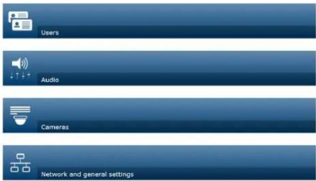
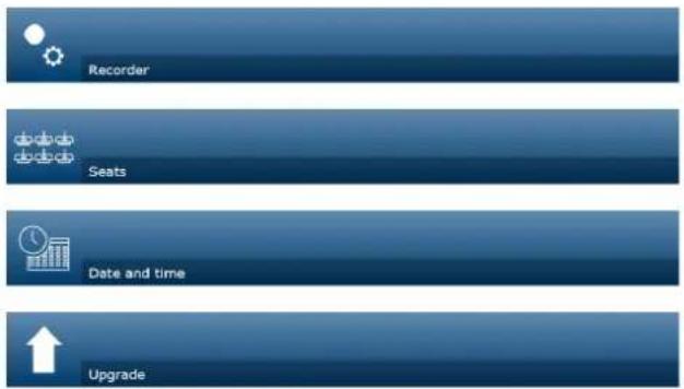


Figure 7.6: CCSD-CURD system settings

Users
Click the Users button on the system settings page to open the user settings page:
This page is used to enter and modify user information and rights.
- To add a user, click the + button to open the 'add new user' screen.
- To change a user's name, select the user (the dark grey color means selected), and then use the panel on the opposite side of the page to make changes.
- To change a user's password, select the user, and then click the 'change password' button.
- To change a user's rights, select the user, and then click the required 'user rights' button.
- To remove a user, select the user, and then click the recycle bin.
For each (new) user, the following can be entered or selected:
- General: Enter First name, Last name, Username, Password (may be empty).
-
User rights: select the required user right (grey means selected):
-
Manage meeting: This right gives access to the manage discussion and manage recorder pages, and volume control. Refer to Manage discussion, page 43 or Manage recorder, page 45.
- Prepare meeting: This right gives access to the prepare discussion pages. Refer to Prepare discussion, page 44.
- Modify users: This right gives access to the users page.
- Configure: This right gives access to the system settings page (excluding the users page, unless the user has the right 'modify users'), the system info and logging pages, and volume control.

- Prepare system: This right gives access to the power page.
Audio
Click the Audio button to open the audio settings page:
- System:
- Master: Master volume to control the loudspeakers of the discussion devices and the PA (audio output 1).
- LSP: Individual volume control for the loudspeakers of the discussion devices.
- PA: Individual volume control for the PA (audio output 1).
- Line input/output: Sets the sensitivity of the analogue audio input and audio output levels 1 and 2 of the Control Unit.
- XLR Microphone: Defines the mode of audio input 1 of the Control Unit:
- When selected, it enables input 1 (XLR) for microphone signal level.
- When not selected, it enables input 1 (RCA socket) for audio line input level.
- Routing options I/O 2: Defines the audio routing mode of input 2 and output 2 of the Control Unit:
- Recorder: Use the recorder mode to connect an external recorder via audio input 2 and output 2.
- Floor: In floor mode, audio input 2 and output 2 are used, and the level is controlled independently.
- Mix-minus: Use the Mix-minus mode to connect two systems via audio input 2 and audio output 2.
- Insertion: In the Insertion mode, audio output 2 and audio input 2 are both used to add signals from external audio devices. For example, connection of an external audio mixer between audio output 2 and audio input 2.
- Line output: Sets the sensitivity of the analogue audio input and audio output levels 3, 4, 5, or 6 of the Control Unit.
- Individual microphone output (CCSD-CURD only): Select the routing of the analogue audio outputs 3, 4, 5 or 6 of the Control Unit:
- Select 3, 4, 5 or 6 to enable selectable microphones for individual recording.
- Digital Acoustic Feedback Suppression (DAFS): Settings for the DAFS function:
- Off: Sets the DAFS function to off.
- Natural: Sets the DAFS function to on.
- Maximum: Sets the system volume to a maximum with minimal risk of acoustic feedback (howling) occurring.
Note: Audio artifacts might occur at higher volume levels.
- Feedback prevention:
- Loudspeaker active when microphone is on: The participant's loudspeaker is active when their microphone is on.
- Attenuate headphone when speaking: Attenuates the headphone volume of the Discussion Devices with 18 dB when selected and the microphone is on.

Cameras
A total of 6 cameras can be connected to the CCS 1000 D Digital Discussion System.
Click the Cameras button to open the camera settings page.
- Overview camera: Sets the camera used as the overview camera.
- SDI Switcher: Enter the IP address of the HD-SDI video switcher. Do not use leading zeros. If leading zeros are entered, the CCS 1000 D Digital Discussion System will not be able to control the switcher.
Example:
- Correct IP address: 192.168.10.111
- Incorrect IP address: 192.168.010.111
- Recycle bin: Click the recycle bin icon to remove the selected camera. Note: Only a disconnected camera can be removed.
- Camera settings overview: Here an overview of all connected cameras is listed. The overview list shows: the Camera name, URL, Serial number, Username, Password, Protocol, and to which video switcher Input the camera is connected to.
- The camera Serial number is used as a link to the camera configuration web pages. Note: Only possible if your PC/laptop or tablet device is connected via the wired Ethernet connection of the system.

Notice!
Ensure that the Bosch ONVIF Camera has firmware 5.80 or higher.
ONVIF cameras
ONVIF cameras are automatically detected, but you still need to:
- Enter a username and password if the camera has a username and password configured.
- Select the switcher input the camera is connected to.
Panasonic and Sony cameras
The system supports Sony IP cameras via CGI commands for 300/360 series, and Panasonic IP cameras via CGI protocol (HD Integrated Camera Interface Specifications 1.06).
Panasonic and Sony cameras are not automatically detected. You need to:
- Manually add the camera using the + button.
- Enter the camera URL (as http:// for a non-secure connection or https:// for a secure connection).
- Enter the username and password for the camera.
- In the Protocol field, select Sony for Sony cameras, and Panasonic for Panasonic cameras.
- Select the switcher input the camera is connected to.
Until the camera is properly connected, a trash can is displayed next to the Camera name allowing you to delete the camera.
Once the camera is connected (the URL, Username, Password and Protocol fields are all correct) you can browse to a specific camera using the link in the Serial number.
Note: Only a disconnected camera can be removed.

Notice!
You can use the Camera name to assign a logical name to the camera, e.g. right rear camera.

Network and general settings
Click the Network and general settings button to open the network and general settings page. Here the network and general settings are displayed and can be set:
Click the Change network settings button to enter/change the network settings:
- Network settings:
- Hostname: The default hostname is CCS1000D
Note: When changing the hostname or (de)activating the fixed IP address in the web browser interface (see below), the laptop/PC might lose the connection with the Control Unit. If this happens, close and then re-open the web browser interface.
- Wired:
- Fixed IP: Select this checkbox if you want to use a fixed IP address. The fields below change from grey to white to indicate that they are activated.
- IP address: Enter a valid IP address.
- Subnet mask: Enter a valid subnet mask.
- Default gateway: Enter a valid default gateway.
- General settings:
- Automatically shutdown the system when not used (energy saving mode): When selected, the control unit is automatically shut down when it is not used for two hours. The ‘waiting list’ and ‘speakers list’ are automatically saved, and will be available when the system is powered on.
Note: This feature does not apply to the voice activation mode.
- Factory default: Click the factory default button to reset all system settings and values to the factory defaults.

Notice!
When the system is reset to the factory defaults, the latest version of the software that the system was upgraded to will be maintained.

Recorder (CCSD-CURD only)
Click the Recorder button to open the recorder settings page.
The following recorder settings are available:
- Source: Select which audio source must be recorded:
- Floor only: The audio of the floor discussion language is recorded.
- Floor and output 3, 4, 5, 6: The audio of the floor discussion language and selected audio output signal (3-6) are mixed and recorded.
- Bit rate: Select the recording audio quality (from 64 kbps (lowest) up to 256 kbps (highest)).
- Automatically pause recording when all microphones are switched off: Recording is paused when no microphone is active.

Seats
Click the Seats button to open the seat settings page.
Here the seat settings for the Discussion Devices can be configured:
- Seats overview:
- (x-y): x = number of Discussion Devices currently connected to the system and initialized. y = historical number of Discussion Devices connected to the system. Click one of the square icons on the left of this page to locate a Discussion Device in the meeting room. When a tick is displayed in the checkbox, the light-ring indicator in the corresponding microphone is lit red and the LED indicator above the microphone button flashes.
Note: This is only possible when the Selection mode checkbox at the left bottom of the page is selected.
- Seat name: Click in the Seat name dialog box and enter/change the seat name as required.
- Mode: The settings in the Mode column can be used to change the function of individual seats/Discussion Devices. A Discussion Device can be configured as an ‘interruption microphone’ that can always get the floor regardless of the number of open microphones. The ‘interruption microphone’ has the same rights as the chairperson except for priority. The participant using the ‘interruption microphone’ is not added to the request list. Typically an interruption microphone is positioned at a podium for use by guest speakers. A total of 25 Discussion Devices can be configured as a chairperson’s device or interruption microphone. For example, 22 chairperson’s devices + 3 interruption microphones = 25 devices in total.
Normal: The Discussion Device operates as a participant device.
Button: The Discussion Device operates as an interruption microphone. The speaker has to push and release the button to enable the microphone and push and release the button again to disable the microphone.
PTT (Push-to-talk): The Discussion Device operates as an interruption microphone. The microphone is enabled for as long as the speaker pushes and holds in the microphone request button.
Note: To use the interruption microphone setting, the slide switch at the base of the discussion device must be set to participant. Refer to Configure Discussion Device, page 36.
- Camera: The camera name connected to the seat.
- Pre-position: Camera preposition setting number assigned to the seat.
- Selection mode (select on Discussion Devices): When selected, a Discussion Device can be located by selecting the seat in the list or by pushing the Discussion Device microphone request button. The Discussion Device LEDs are illuminated.
- When the ‘selection mode’ is active, the Discussion Devices cannot be used for discussion. They can, however, still be selected/located.
- De-init button: When clicked, it erases the address/subscription of the selected Discussion Device:
- The light-ring in the head of the microphone is lit red.
- The LED indicator above the microphone button is lit amber.
Initialize the Discussion Device as described in Initialize Discussion Device, page 36.
- Remove disconnected seats button: Removes the subscribed seats from the seats overview.

Date and time (CCSD-CURD only)
Click the Date and time button to open the date and time settings page.
Click the Change date and time settings button to select:
- Time: Select the local time.
- Date: Select the current date.

Upgrade

Notice!
Upgrade is not available on tablets.
- Select: Used to select and deselect products (rows) on the Upgrade page.
- Device name: The name of the product being upgraded.
- Type: Type of product being upgraded.
- Version: Software version that the product will be upgraded to.
- State: State of the software upgrade (Idle, Programming, Rebooting, Done, or Failed after reboot). If the upgraded file is corrupt or not recognized, an error message is displayed.
- Progress: Progress bars for indicating the status of the software upgrade.
- Start button: Starts the software upgrade.
Click the Upgrade button to open the software upgrade page.
The Upgrade page is used to upgrade/maintain the software of the control unit:
- Download the upgrade software file from the product related page at: https://licensing.boschsecurity.com/software
- From the upgrade page, click in the file box to select your saved software file.
- If you selected a correct firmware file, the control unit is selected automatically.
-
Click the start button to start the upload process:
-
Progress bars are displayed.
- The upload status is shown in the 'state' column. If the upgraded file is corrupt or not recognized, an error message is displayed.
-
Software versions (numbers) are shown in the 'version' column. The uploaded software version number is only shown when the upgrade is successfully completed.
-
Exit the upgrade page after completion of the upload process ('done'state).
-
Clear the browser cache (history), so that the new functionality is displayed in the web browser.
7.4.7 Power

Preconditions:
- The logged on user must have the access right: Prepare system.
Click the Power button on the homepage to display the 'power' pop-up window.
- On: Activates the Control Unit: After a few seconds, the system is ready for use.
- Standby: Sets the Control Unit to 'standby' and switches off the Discussion Devices:
- All LEDs on the Discussion Devices go out.
- To indicate that the Control Unit is in ‘standby’, the green power on LED on the front panel is lit, and the Discussion Devices volume control LED flashes slowly. All other LEDs are off.
- The ‘waiting list’ and ‘speakers list’ are cleared.
- Recording is stopped, if active.
- Cancel: Closes the power pop-up window.
7.4.8 Logging

Preconditions:
- The logged on user must have the access right: Configure.
Click the Logging button on the homepage to open the logging page.
Logging is used for automatically saving system events, such as date, time and (error) type of the event:
- Use the 'clear view' button to clear the logging view. The logged events will not be deleted and will be displayed when the logging page is reopened. When the logging view is cleared, the logged events can still be exported.
- Use the 'export' button to export and save the current event logging overview file (*.txt format) on the hard-drive of your tablet / PC.
7.4.9 System info

Preconditions:
- The logged on user must have the access right: Configure.
Click the System info button on the homepage to open the system info page. The following information is displayed:
- Device type
- Host name
- Ethernet MAC address
- Ethernet IP address
- Ethernet Subnet mask
- Ethernet Default gateway
- Version
- API
- Link to download the Open Source Software license terms
System info is used by a technician.
7.4.10 Logout

Click the Logout button on the homepage to log out from the discussion application.
The login page is displayed.
7.5 RESTful Application Program Interface (API)
The CCS 1000 D Digital Discussion System has a RESTful API that has the following functions:
Note: A RESTful API is an Application Program Interface that uses HTTP requests to GET, PUT, POST and DELETE data.
Speakers
This function gives control of the speaker's microphones. A list of all active speakers can be retrieved. Speakers can be added to and removed from the speakers list. Possible applications that could use this function are:
- third party Pan Tilt Zoom (PTZ) camera systems.
- web-casting and recorder solutions requiring microphone information.
– synoptic layouts for microphone management.
Waiting-list
This function gives control of the waiting list. A list of all waiting speakers can be retrieved.
Speakers can be added to and removed from the waiting list.
Possible applications that could use this function are:
- third party Pan Tilt Zoom (PTZ) camera systems.
– web-casting and recorder solutions requiring microphone information. - synoptic layouts to enable and disable microphones.
System
This function gives the possibility to:
- set the system to standby.
– recover the system from standby.
Seats
This function gives the possibility to retrieve and set microphone sensitivity of an individual device. The sensitivity range is from -6dB to +9dB.
For more information on the Application Program Interface, refer to the API manual, which can be downloaded at: https://licensing.boschsecurity.com/software
8 Operation
This section describes how to operate the CCS 1000 D Digital Discussion System.
8.1 Recording and playing back discussion
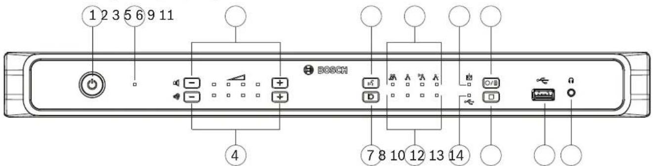
Figure 8.1: CCSD-CURD
The built-in recorder is used to record discussions in the MP3 format. Recordings are saved to the internal memory or an appropriate USB memory stick, when connected. Refer to the information on USB memory stick in Additional components, page 14.
During recording, the full capacity of the USB memory stick may not be used because:
- Multi-device USB memory sticks are supported, but only one internal memory device on the USB memory stick is used.
- USB devices with multiple partitions are supported, but only the first partition is used.
The memory size of the USB stick and recording settings determine the total recording time.
The internal memory can save up to 8 hours of discussion at the lowest bit rate. For an overview of the possible recording times compared to the bit rate, see Technical data, page 63.
The appropriate memory (internal/USB) and LED indicator are automatically selected and deselected when the USB memory stick is inserted and removed from the USB connector at the front of the Control Unit.
Recording options
When recording is started, the MP3 recorder automatically creates an MP3 file, using the current date and time as the file name.
Recordings saved on the USB memory stick have the filename: 'USB:yyyymmdd-hhmmss-Floor.mp3'.
- If the recording setting source is set to Floor and output x (x = 3, 4, 5 or 6), a second recording file is stored with the same date-time stamp: 'USB:yyyymmdd-hhmmss-Outputx.mp3'.
- If the recording is made on the internal memory, the file name starts with 'IM' instead of 'USB'.
By default, recorded files have a maximum duration of 60 minutes. After 60 minutes, the file is automatically closed, and a new file is created. This process is repeated as long as recording is active or until the internal memory or USB stick is full.
If you want discussion to be recorded to one continuous file, a 'no-file-split', should be created in the internal flash of the Control Unit. To do this:
-
Connect a laptop or PC to the Control Unit, by using the micro USB connector at the rear of the Control Unit..
-
Under the detected drive for the Control Unit, create a txt file called 'no-file-split'.
-
Remove the file extension ".txt."
To reset recorded files to a maximum duration of 60 minutes, delete the 'no-file-split' file.
Making a recording

Notice!
It is recommended to use a USB memory stick for external recording. If required, an external recorder can be connected to RCA 'Audio Out (2)' of the Control Unit.

Notice!
Make a back-up of the files on your USB memory stick before inserting it into the control unit.
-
Connect a USB memory stick to the USB connector (13) at the front of the Control Unit. The USB recording LED indicator (10) will light up green to indicate that the stick has been detected and recording can begin.
-
Press the 'start/pause' recording button (11) to start a recording session. The LED indicator will turn red to indicate that recording is active.
- To pause recording, press the 'start/pause' recording button again. The LED indicator will flash red to indicate that recording is temporarily stopped.
- To resume recording, press the 'start/pause' recording button again. The LED indicator will turn red to indicate that recording is active.
- To stop recording press the ‘stop recording’ button (12). The LED indicator will turn green to indicate that the recording session is complete.
Recording will automatically stop when:
- Internal recording is taking place and a USB memory stick is inserted into the USB connector (13) at the front of the Control Unit.
- External recording is taking place and the USB memory stick is removed from the Control Unit. Only remove the USB memory stick when the green recording LED is on.
- The internal memory is full when recording internally.
- The USB memory stick is full when recording on USB memory stick.
Playing back a recording
To playback a recording either:
- Connect a tablet, laptop, or PC to the Control Unit, via the Ethernet connection, and use the web browser interface to select which recording has to be played back. See Web browser interface, page 38.
- Remove the USB memory stick, and transfer the MP3 file(s) to a PC.
- Download the MP3 file(s) from the internal memory of the Control Unit to a PC, by using the micro USB connector at the rear of the Control Unit.

Notice!
Recordings cannot take place when the Control Unit is connected to a PC with the micro USB connector.
8.2 Using the microphone button
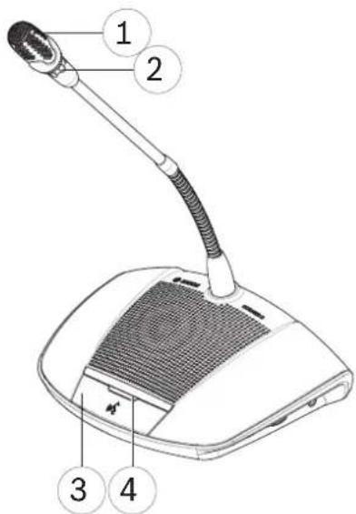
Figure 8.2: Device with participant's button fitted
Use the microphone button (3) on your device to activate and deactivate your microphone (1) as required. The LED indicator (4) above the microphone button and light-ring (2) in the head of the microphone will indicate the status of your device. The following color codes are used:
White (possible-to-speak indication)
This indicator is only above the microphone button and not in the light-ring.
- You can activate your microphone immediately by pressing the microphone button.
- Your request to speak will not be added to the waiting list.
Green
- Your request to speak has been added to the waiting list.
- The waiting list can be viewed and managed in the web browser interface.
Green flashing
- Your request to speak is first in the waiting list.
- As soon as the active speaker disables their microphone button you will be allowed to speak.
Red
- Your microphone is active; you are allowed to speak.
All LEDS off
- The device is off.
8.3 Using the priority button
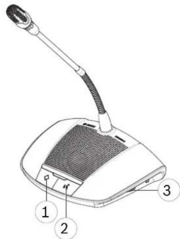
Figure 8.3: Device with chairperson's button fitted
When the device is configured as a chairperson's device, the priority button (1) can be pressed and held in to override all participant microphones. A chime (when selected in the web browser interface, see Web browser interface, page 38) is sounded at the same time. The chairperson's microphone button (2) is used to activate and deactivate the microphone as required.
8.4 Adjusting headphones volume
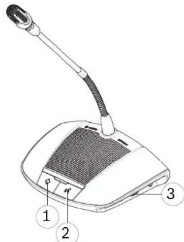
Figure 8.4: Device with chairperson's button fitted
Use the rotary thumbwheel (3) on the side of the device to adjust the volume of the headphones, when connected.
9 Troubleshooting
Use the following Troubleshooting table to troubleshoot the CCS 1000 D Digital Discussion System.
9.1 Troubleshooting table
| Problem Possible cause Possible solution | ||
| No sound from loudspeakers of all Discussion Devices. | Loudspeaker volume too low. | Use the volume control button on the Control Unit or web browser interface to centrally increase the volume of all Discussion Devices. |
| No sound from loudspeaker of a Discussion Device. | Headphones are connected to the Discussion Device. | Remove the headphones. |
| Faint or distorted sound from Discussion Device. | One or more trunk lines are overloaded. | Reduce the load on the trunk-lines:- Reduce the number of Discussion Device, or- Reduce the length of the extension cable(s). |
| Brief interruption in the audio during a meeting/discussion. | - Recorder settings changed during a meeting/discussion.- Individual microphone outputs changed during a meeting/discussion. | Do not change settings during a meeting/discussion. |
| Microphone does not respond. | One or more trunk lines are overloaded. | Reduce the load on the trunk-lines:- Reduce the number of Discussion Devices, or- Reduce the length of the extension cable(s). |
| Acoustic feedback from Discussion Devices. | An acoustical path is created between a loudspeaker and a microphone. | - Use the volume control on the Control Unit to centrally decrease the volume of all Discussion Devices.- Decrease the volume of the Control Unit loudspeaker.- Increase the distance between the Discussion Devices and/or the Control Unit.- Increase the distance between the headphone and the microphone of aDiscussion Device.Disconnect the headphone when not used.- At the audio settings page, make sure: “Digital Acoustic Feedback Suppression” (Natural or Maximum) and “Attenuate headphone when speaking” are selected. “Loudspeaker active when microphone is on” should be deselected.- Do not get too close to the microphone capsule when speaking.- Avoid holding and covering the microphone capsule with your hand. |
| Incorrect response from LED indicator above microphone button. | Incorrect microphone mode selected. | Check microphone mode and change mode if required. |
| Configuration switch at base of Discussion Device incorrectly set. | Set the configuration switch to either participant’s device or chairperson’s device. See Discussion Device, page 36.The configuration mode can be set in the Seats page of the web browser interface. | |
| No sound from loudspeaker of CCSD-CURD. | Loudspeaker volume too low. U | Use the volume control button on the Control Unit or web browser interface to increase the volume of the loudspeaker. |
| Headphones are connected to the control unit. | Remove the headphones. | |
| Recording to the internal memory not possible. | Internal memory full or USB connected. | - Check internal recording LED indicator: Red/green flashing indicates that the internal memory is full.- Connect a USB cable to the micro USB connector at the rear of the Control Unit and transfer files to a PC if necessary.- Remove recordings. |
| The display and control of recordings becomes slow. | When there are a lot of recordings stored loading, the Manage recorder page loads slower since information about all these recordings needs to be loaded. | Delete redundant recordings to decrease the loading time of the Manage recorder page. |
| Recording to USB memory stick not possible. | USB memory stick not fully inserted in Control Unit. | - Make sure the USB memory stick is fully inserted.- Check that the USB recording LED indicator is green: Indicates that the USB memory stick is selected and the Control Unit is ready for recording. |
| USB memory stick incorrect type or incorrectly formatted. | Make sure the USB memory stick: is of the correct type and is correctly formatted.Refer to USB memory stick in Additional components, page 14. | |
| USB memory stick too large. Do not use a USB memory stick larger than 128 GB. | ||
| USB memory stick full. - Check internal recordingLED indicator: Red/green flashing indicates that the internal memory is full.- Connect the USB memory stick to a PC, and transfer the files to a hard disk if necessary. | ||
| USB memory stick damaged. - | Check the read/write possibilities of the USB stick.- Note: If the Control Unit does not detect the USB memory stick, it willautomatically record files to the internal memory instead.- Replace the (faulty) USB memory stick. | |
| Poor web browser performance. | Multiple users are logged into the same web browser. | Make sure only one user is logged into a web browser. If multiple users need to log in at the same time:- use a different browser type for each user, or- log in using a separate device (tablet, laptop or PC). |
| The tablet, laptop or PC loses the connection with the control unit. | - Activating or deactivating the fixed IP address in the web browser interface.- Changing the hostname. | Close and then reopen the web browser interface. |
| Part of system not working correctly. | Interrupted system cabling. - Check all trunk connections between the Discussion Devices and the Control Unit.- Check the connections of the auxiliary equipment. | |
| The external SDI video switcher does not switch between inputs. | Switcher has incorrect settings. | Reset the switcher to factory defaults. Then set the TCP connection port number.- For the Kramer MV-6 switcher, set the TCP connection port number to 5000.- For the tvOne CORIOmatrix switcher, set the TCP connection port number to 10001. |
10 Maintenance
The CCS 1000 D Digital Discussion System requires minimum maintenance. To ensure for trouble-free operation, clean and inspect the system components on a regular basis:
10.1 Cleaning

Caution!
Do not use alcohol, ammonia, petroleum solvents or abrasive cleaners to clean the system components.
- Disconnect the Discussion Devices from the system cabling.
- Clean the Discussion Devices with a soft cloth slightly moistened with a weak soap and water solution.
- Wait until the Discussion Devices are fully dry before reconnecting them to the system cabling.
- Clean the Control Unit and optional Extension Unit with a soft cloth, as required.
10.2 Inspect components
- Check all CCS 1000 D Digital Discussion System components for signs of wear and tear. Replacement Discussion Devices can be ordered from your Bosch representative, if required.
- Check all connectors and system cabling for damage.
- Check the Discussion Device microphone buttons for correct operation. The buttons should not be loose or remain pressed in when operated.
10.3 Storage
If you do not intend to use the CCS 1000 D Digital Discussion System for a while:
- Disconnect the 24 VDC power supply from the mains and from the rear of the Control Unit.
- Disconnect the Discussion Devices from the system cabling.
- Store the system components and system cabling in a clean, dry area with sufficient ventilation.
For the maximum and minimum storage temperatures, refer to Technical data, page 63.
11 Technical data
This section contains the technical specifications of the CCS 1000 D Digital Discussion System.
11.1 Control Unit
Electrical
| Supply voltage Adaptor 100 to 240 VAC, 50/60 | Hz |
| Current Consumption voltage Adaptor 1.9 A (100 VAC) to 1 A 240 (VAC) | |
| DC voltage Control Unit 24 V, 6.0 A | |
| Maximum number of Discussion Devices for Control Unit (without Extension Unit) | 40 Discussion Devices per trunk80 Discussion Device in total24 V, Max 5.2 A (short-circuited protected) |
| Discussion Device loudspeakers volume control | 15 steps of 1.5 dB (starting from -10.5 dB) |
| Limit threshold level to unit 12 dB above nominal level | |
| Gain reduction due to number of open microphones (NOM) | 1/SQRT (NOM) |
| Sample rate 44.1 kHz | |
| Frequency response 30 Hz to 20 kHz | |
| Ethernet speed 1 Gb/s | |
Total Harmonic Distortions (THD)
| Nominal input (85 dB SPL) < 0.5% | |
| Max. input (110 dB SPL) < 0.5% |
Audio inputs
| XLR nominal microphone input -56 dBV | |
| XLR maximum microphone input | -26 dBV |
| RCA nominal input | -24 dBV (+/- 6 dB) |
| RCA maximum input | +6 dBV |
| S/N | >93 dBA |
| Frequency response | 30 Hz to 20 kHz |
| THD | <0.1% |
Audio outputs
| RCA nominal output | -24 dBV (+6/- 24 dB) |
| RCA maximum output +6 dBV | |
| S/N > 93 dBA | |
| Frequency response 30 Hz to 20 kHz | |
| THD <0.1% |
Environmental
| Operating temperature 5 °C to +45 °C | (+41 °F to +113 °F) |
| Storage and transport temperature -40 °C to + | 70 °C(-40 °F to +158 °F) |
| Relative humidity 5% to 98% non-condensing |
11.2 Discussion Device
Electrical
| Power consumption 1.3 W | |
| Frequency response 30 Hz to 20 kHz (System electrical) | |
| THD <0.5 % | |
| S/N >93 dBA | |
| Sampling rate | 44.1 kHz |
| Headphones load impedance | >32 ohms < 1k ohm |
| Loudspeaker max. peak output power | 4 W |
Acoustical
| Loudspeaker nominal output | 72 dB SPL |
| Participants loudspeaker frequency response | 200 Hz to 16 kHz (acoustical) |
| Microphone polar pattern | Cardioid |
| Participants microphone frequency response | 125 Hz to 15 kHz |
| Microphone nominal input | 85 dB SPL |
Mechanical
| Dimensions device without microphone (H x W x D) | 64 x 203 x 146 mm(2.5 x 8.0 x 5.7 in) |
| Height with microphone in horizontal position | 130 mm (5.1 in) |
| Length of microphone from mounting surface | CCSD-DS: 310 mm (12.2 in)CCSD-DL: 480 mm (18.9 in) |
| Weight | Approx. 1 kg (2.2 lb) |
| Mounting Tabletop (portable or fixed) | |
| Material (top) Plastic ABS+PC | |
| Material (base) Metal ZnAl4 | |
| Color (top) Traffic black (RAL 9017) matt-gloss | |
| Color (base) Pearl light grey (RAL 9022) matt-gloss |
Environmental
| Operating temperature 0 °C to +35 °C | (+32 °F to +95 °F) |
| Storage and transport temperature -40 °C to + | 70 °C(-40 °F to +158 °F) |
| Relative humidity 5% to 98% non-condensing | |
| Air pressure 600 to 1100 hPa |
11.3 Extension Unit
Electrical
| Supply voltage Adaptor 100 to 240 VAC, 50/60 Hz | |
| Current Consumption voltage Adaptor 1.9 A (100 VAC) to 1 A 240 (VAC) | |
| DC voltage Control Unit 24 V, 6.0 A | |
| Maximum number of Discussion Devices per Extension Unit | 40 Discussion Devices per trunk/tap-off85 Discussion Devices in total24 V, Max 5.2 A (short-circuited protected) |
Mechanical
| Dimensions including feet(H x W x D) | 45 x 440 x 200 mm(1.8 x 17.3 x 7.9 in)19" wide, 1 RU high |
| Height of feet 5.5 mm (0.2 in) | |
| Mounting Tabletop or 19" rack | |
| Weight Approx. 4.12 kg (9.1 lb) | |
| Material (top and base) Painted metal | |
| Color (top and base) Traffic black (RAL 9017) | matt-gloss |
| Rim front panel Pearl light grey (RAL 9022) | matt-gloss |
Environmental
| Operating temperature 5 °C to +45 °C | (+41 °F to +113 °F) |
| Storage and transport temperature -40 °C to + | 70 °C(-40 °F to +158 °F) |
| Relative humidity | 5% to 98% non-condensing |
11.4 Safety compliance
The section contains safety compliance information for:
- the CCSD-CU Control Unit
- the CCSD-CURD Control Unit
- the CCSD-DS Discussion Device
- the CCSD-DL Discussion Device
- the CCSD-EXU Extension Unit
11.4.1 Control Units
| EU CE, WEEE | 1 |
| US UL, FCC | |
| CA CSA, ICES-003, EPS | 1 |
| KR KCC, KC | ^1 , K-MEPS ^1 |
| AU/NZ RCM, MEPS | 1 |
| RU/KZ/BY EAC | |
| JP PSE | 1 |
| CN China RoHS, CCC | 1 |
| TW BSMI | 1 |
| SA SASO |
Note: ^1 Only applicable for the power adaptor.
11.4.2 Discussion Devices
| EU CE, WEEE | |
| US FCC | |
| CA ICES-003 | |
| KR KCC | |
| AU/NZ RCM | |
| RU/KZ/BY EAC | |
| CN China RoHS | |
| SA SASO |
11.4.3 Extension Unit
| EU CE, WEEE | 1 |
| US UL, FCC | |
| CA CSA, ICES-003, EPS | 1 |
| KR KCC, KC | ^1 , K-MEPS ^1 |
| AU/NZ RCM, MEPS | 1 |
| RU/KZ/BY EAC | |
| JP PSE | 1 |
| CN China RoHS, CCC | 1 |
| TW BSMI | 1 |
| SA SASO |
Note: ^1 Only applicable for the power adaptor.
Bosch Security Systems B.V.
Torenallee 49
5617 BA Eindhoven
Netherlands
www.boschsecurity.com
© Bosch Security Systems B.V., 2020
- Digital Discussion System
- Safety
- Old electrical and electronic appliances
- Class A Notice for FCC and ICES 003
- Business Equipment
- For commercial or professional use
- About this manual
- Manual purpose
- Digital document
- Intended audience
- Alerts and notice signs
- Notice!
- Caution!
- Warning!
- Danger!
- Copyright and disclaimer
- Document history
- System overview
- CCSD-CU(RD) Control Unit
- Control Unit with MP3 recording and DAFS
- Discussion Device
- CCSD-EXU Extension Unit
- GUI languages
- Planning
- Unpacking
- Delivered with products
- CCSD-CU Control Unit or CCSD-CURD Control Unit
- CCSD-Dx Discussion Device
- Quantity Component
- CCSD-EXU Extension Unit
- Additional components
- Making custom extension cables
- Setup options and limits
- Small/medium sized system (max. 80 Discussion Devices)
- Large system (max. 245 Discussion Devices)
- Extension cables
- Installation
- Install Unit(s)
- Connections
- Connect system components
- Control Unit connections
- Refer to
- Discussion Device connections
- Extension Unit connections
- Configuration
- Control Unit
- Discussion modes
- 88
- Open
- 8
- Override
- Voice
- Push To Talk (PTT)
- Key combinations
- Extension Unit
- Discussion Device
- Configure Discussion Device
- Initialize Discussion Device
- Erase address
- Web browser interface
- First use configuration
- Web browser
- Preconditions
- Create a connection to the web browser interface
- Log in and update the system software
- Login
- First time login
- Normal login
- Manage discussion
- Preconditions:
- Manage discussion means:
- Recording (CCSD-CURD only)
- Master volume control
- Prepare discussion
- Prepare discussion means:
- - Discussion mode:
- - Speakers options:
- - Waiting options:
- - Priority options:
- Manage recorder
- - Playback:
- System settings
- Users
- Audio
- - System:
- - Feedback prevention:
- Cameras
- Example:
- ONVIF cameras
- Panasonic and Sony cameras
- Network and general settings
- - Wired:
- - General settings:
- Recorder (CCSD-CURD only)
- Seats
- - Seats overview:
- Date and time (CCSD-CURD only)
- Upgrade
- Power
- Logging
- System info
- Logout
- RESTful Application Program Interface (API)
- Speakers
- Waiting-list
- System
- Operation
- Recording and playing back discussion
- Recording options
- Making a recording
- Playing back a recording
- Using the microphone button
- White (possible-to-speak indication)
- Green
- Green flashing
- Red
- All LEDS off
- Using the priority button
- Adjusting headphones volume
- Troubleshooting
- Maintenance
- Cleaning
- Inspect components
- Storage
- Technical data
- Control Unit
- Discussion Device
- Extension Unit
- Safety compliance
- Control Units
- Discussion Devices
- Extension Unit
Brand : BOSCH
Model : CCSD-DS
Category : Microphone