
GCI-K1812W - Security Camera GRUNDIG - Free user manual and instructions
Find the device manual for free GCI-K1812W GRUNDIG in PDF.


| Product Type | Security Camera |
| Brand | Grundig |
| Model | GCI-K1812W |
| Dimensions | 70 x 70 x 130 mm (without bracket) |
| Weight | Approximately 350 g |
| Power Supply | PoE (IEEE 802.3af) or 12V DC adapter (included) |
| Resolution | 1920 x 1080p (Full HD) at 25/30 fps |
| Night Vision | Up to 30 m with IR LEDs |
| Field of View | 90° (horizontal), 50° (vertical) |
| Motion Detection | Yes, configurable sensitivity and zones |
| Audio | Built-in microphone for one-way audio |
| Weatherproof Rating | IP66 (suitable for outdoor use) |
| Connectivity | Ethernet (RJ45) for PoE; Wi-Fi 802.11b/g/n (2.4 GHz) |
| Storage | MicroSD slot up to 128 GB; cloud storage compatible |
| Maintenance & Cleaning | Wipe gently with a soft, dry cloth. Avoid solvents or abrasive materials. |
| Safety | Do not expose to extreme temperatures or humidity. Keep out of reach of children. |
| Spare Parts & Repairability | Use only Grundig-approved parts and authorized service centers. Contact support for repairs. |
| General Information | Compatible with Grundig Smart Home app. Supports ONVIF Profile S. |
Frequently Asked Questions - GCI-K1812W GRUNDIG
User questions about GCI-K1812W GRUNDIG
0 question about this device. Answer the ones you know or ask your own.
Ask a new question about this device
Download the instructions for your Security Camera in PDF format for free! Find your manual GCI-K1812W - GRUNDIG and take your electronic device back in hand. On this page are published all the documents necessary for the use of your device. GCI-K1812W by GRUNDIG.
USER MANUAL GCI-K1812W GRUNDIG
natural_image
White camera lens with a dome and central lens, labeled 'GRUNDIG' (no other text or symbols visible)Content:
-
Introduction 1
-
Important Safety Instructions 2
-
Package Contents 2
-
Installation 2
-
Camera Overview 3
- System Requirements 3
- Ethernet Connection 3
-
Installation and Connection 4
-
Accessing the Camera 4
-
Video Resolution Setup 9
-
Browser-based Viewer Introduction 12
-
Home Page 13
-
System Related Settings 15
-
Host Name & System Time Setting 15
- Security 16
- Network 24
-
DDNS 30
-
Mail 31
-
FTP 32
-
HTTP 33
-
Motion Detection 34
-
Network Failure Detection 38
-
Tampering 39
-
Storage Management (on Camera) 41
-
Recording (on Camera) 44
-
File Location (on PC) 45
-
View Log File 46
-
View User Information 47
16.View Parameters 49 - Factory Default 49
- Software Version 50
- Software Upgrade 51
- Maintenance 52
10. Streaming Settings
- Video Format 53
- Video Compression 55
- Video OCX Protocol 57
- Video Frame Rate 58
- Video Mask 59
11. Camera Settings
- Exposure Setting 60
- White Balance Setting 61
- Picture Adjustment 62
- Backlight Setting 62
- Digital Zoom Setting 62
- WDR Function 63
- Noise Reduction 63
- TV System Setup 63
12. Logout
- CMS Software Introduction 64
- Internet Security Settings 65
- GRUNDIG Viewer Download Procedure 68
- Install UPnP Components 70
- Deleting the Existing GRUNDIG Viewer 72
1. Introduction
Following the high standards of GRUNDIG IP Cameras, this IP Camera is capable of serving real-time streaming and makes the images run smoothly (25 images/second).
In addition to MJPEG real time streaming, this IP Camera develops a superior H.264 main profile codec to smoothly transfer High Definition surveillance data through the Internet without distortion. Attributing to the IP Camera's flexible platform, the camera can be applied in various installation locations including shops, stores, banks, parking lots, factories and building surveillance.
With the Power over the Ethernet (IEEE 802.3af) feature, the need of power outlets could be totally eliminated. Likewise installation and cabling cost can be significantly reduced. Additionally, its light weight and compact size offer a quick and simple installation on ceilings or walls of houses and vehicles.
2. Important Safety Instructions
Be sure to use only the standard adapter that is specified in the specification sheet. Using any other adapter could cause fire, electrical shock, or damage to the product. Incorrectly connecting the power supply may cause explosion, fire, electric shock, or damage to the product. Do not connect multiple products to one single adapter. Exceeding the capacity may cause abnormal heat generation or fire.
Do not place conductive objects (e.g. screwdrivers, coins or any metal items) or containers filled with water on top of the product. Doing so may cause personal injury due to fire, electric shock, or falling objects.
If any unusual smells or smoke comes out of the unit, stop using the product. In this case, immediately disconnect the power source and contact the service center. Continued use in such a condition may cause fire or electric shock.
If this product fails to operate normally, contact the nearest service center. Never disassemble or modify this product in any way. (GRUNDIG is not liable for problems caused by unauthorised modifications or attempted repair.)
To prevent fire or electric shock, do not expose the inside of this device to rain or moisture.
3. Package Contents
These parts are included:
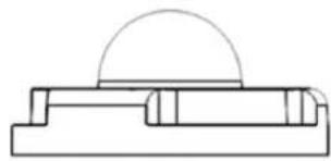
natural_image
Pure technical line drawing of a mechanical component with no text or symbolsCamera (with Cable)
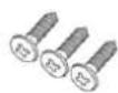
Self-Tapping Screws
[x3]
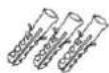
Plastic Anchors (x3)

Security Screw
[x1]
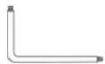
Security Torx

Rubber Washer (x1, Casing)
Rubber Washers (x3, Baseplate)
Quick Guide

CD
4. Installation
Do not install the product in a location subject to high temperature (over 50°C), low temperature (below -10°C), or high humidity. Doing so may cause fire or electric shock. Keep out of direct sunlight and heat radiation sources. This may cause fire. Avoid aiming the camera directly towards extremely bright objects such as the sun, as this may damage the image sensor.
Do not install the unit in humid, dusty or sooty locations. Doing so may cause fire or electric shock. Install it in a place with good ventilation.
When installing the unit, fasten it securely and firmly. A falling unit may cause personal injury.
If you want to relocate the already installed product, be sure to turn the power off and then move or reinstall it.
4.1. Camera Overview
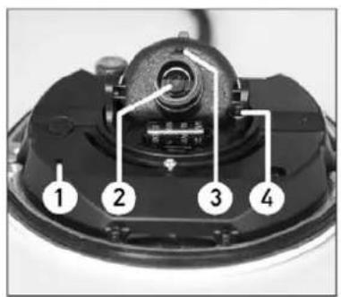
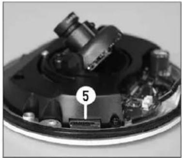
natural_image
Close-up of a mechanical component with numbered annotation (5) on a circular base, no readable text or symbols present.| Designation | Description | |
| 1 | Reset Button | Restore to default setting; press the button with a proper tool |
| 2 | Lens | Rotate the lens to the right or left to adjust the focus |
| 3 | Fixed Focus Screw | Loosen the screw to adjust the lens |
| 4 | Fixed Tilt Screw | Loosen the screw to adjust the tilt angle |
| 5 | Micro SD Card Slot | For Micro SD Card recording |
4.2. System Requirements
To perform the IP Camera via web browser, please ensure your PC is in good network connection, and meets the system requirements as described below.
Personal Computer :
1.] Intel Pentium M, 2.16 GHz or Intel Core 2 Duo, 2.0 GHz
2.) 2 GB RAM or more
Operating System :
Windows XP / Windows VISTA / Windows 7
Web Browser :
Microsoft Internet Explorer 6.0 or later
Firefox
Chrome
Safari
Network Card :
10Base-T (10 Mbps) or 100Base-TX (100 Mbps) operation
Viewer :
ActiveX control plug-in for Microsoft IE
4.3. Ethernet Connection
For waterproofing the RJ-45 Dongle please use a corresponding Screw-On Plug (not included in the package). Please refer to the instructions for the Screw-on Plug to waterproof the connection correctly.
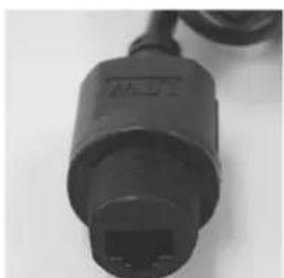
natural_image
Close-up of a black USB cable connector with a port socket (no visible text or symbols)RJ-45 Dongle
4.4. Installation and Connection
To make sure that the camera is waterproof, please follow the following installation procedure:
Step 1: Please refer to 4.3. Ethernet Installation to connect the cable.
Step 2: Put the Rubber Washers into the holes that are located on both sides of the Bottom Plate of the Camera.
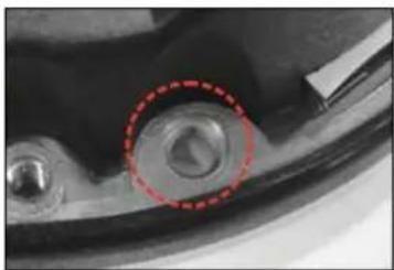
natural_image
Close-up of a mechanical component with a red dashed circle highlighting a circular feature (no visible text or symbols)Step 3: Aim the installation holes at the target installation position and fasten the screws to attach the Camera to the ceiling.
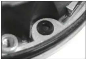
natural_image
Close-up of a mechanical component with circular features and a central hole (no visible text or symbols)NOTE: The supplied self-tapping screws are mainly for softer substrate/material installation, such as wood. For other installation environments such as a cement wall, it is required to pre-drill and to put the plastic anchors into the holes before fastening the supplied self-tapping screw to the wall.
Step 4: Please refer to 4.1. Camera Overview to adjust the lens.
Step 5: Aim the arch parts on both Dome Cover and Bottom Plate to attach the two parts firmly together. And then fasten the security screws on the Dome Cover to finish the installation of the Camera.
5. Accessing the Camera
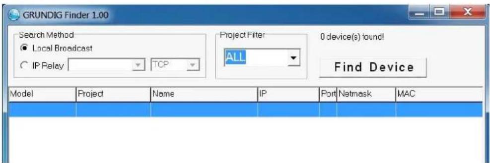
For initial access to the IP Camera, users can search the camera through the installer program: GRUNDIG Finder.exe, which can be found on the supplied CD.
GRUNDIG Finder Software Setup :
Step 1: Double-click on the program GRUNDIG Finder.exe (see the desktop icon below). Its window will appear as shown below. Then click on the "Find Device" button.

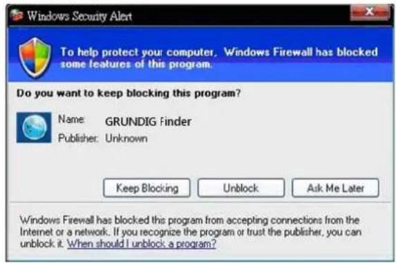
Step 2: The security alert window will pop up. Click "Unblock" to continue.
Device Search :
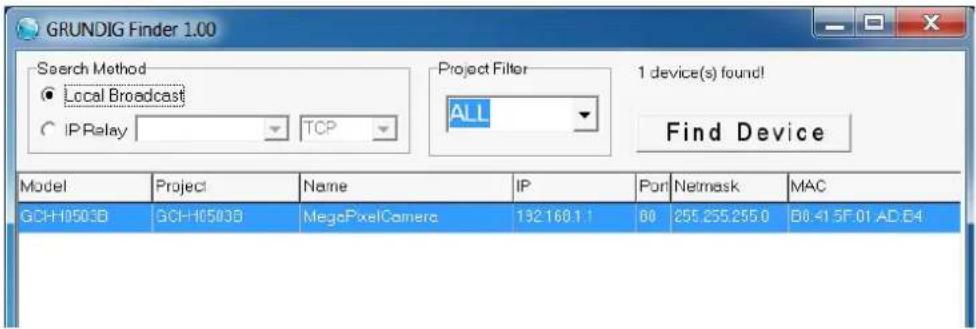
Step 3: Click "Find Device" again, afterwards all IP devices found will be listed on the page, as shown in the picture below. The IP Camera's default IP address is: 192.168.1.1.
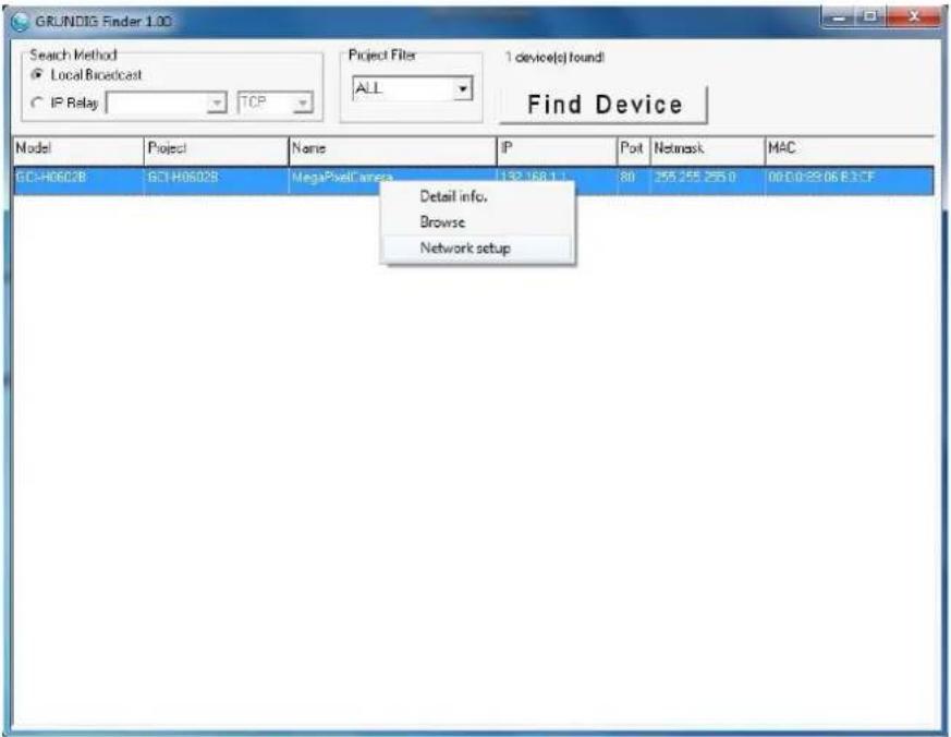
Step 4: Double-click or right-click and select "Browse" to access the camera directly via the web browser.
Step 5: Then the dialogue box for entering the default user name and password (as shown below) will appear for login to the IP Dome Camera.
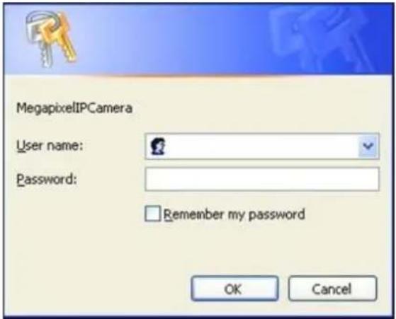
The default login ID and password for the Administrator are:
Login ID: admin
Password: 1234
NOTE: ID and password are case sensitive.
It is strongly advised to alter the administrator's password due to security concerns. Please refer to section 9.2. Security for further details.
Additionally, users can change the IP Camera's network property, either to DHCP or Static IP, directly in the device finding list. Please refer to the following section for changing the IP Camera's network property.
Example of changing the network property of the IP Camera :
Users can directly change an IP Camera's network property, e.g. from static IP to DHCP, in the finding device list. The procedure to change the IP Camera's network property is explained below:
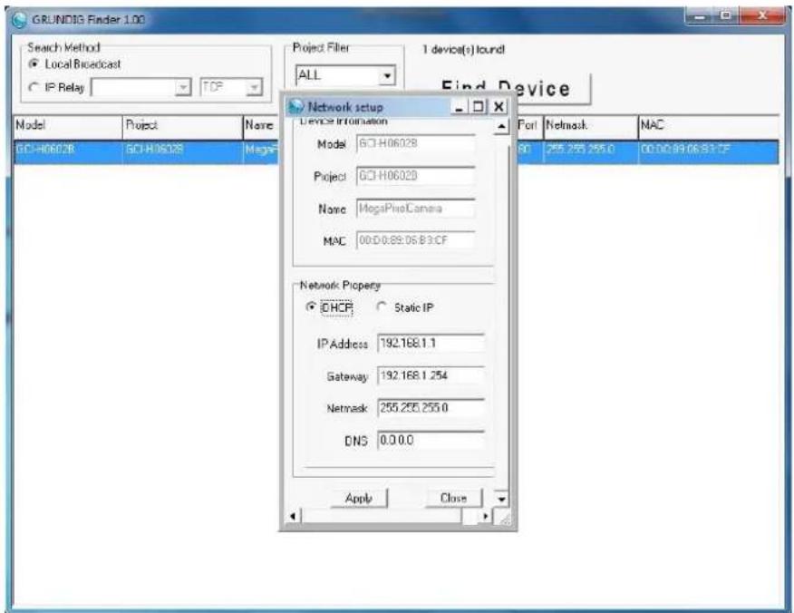
Step 1: In the finding device list, click on the IP Camera of which you would like to change the network property. Right-click on the selected item, and select "Network Setup". Meanwhile, record the IP Camera's MAC address for future identification.
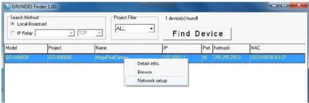
Step 2: The "Network Setup" page will come out. Select "DHCP," and click on the "Apply" button at the bottom of the page.
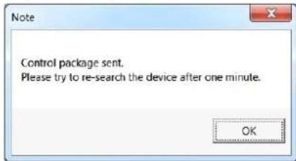
Step 3: Click on "OK" in the Note of setting the change. Wait for one minute to search again for the IP Camera.
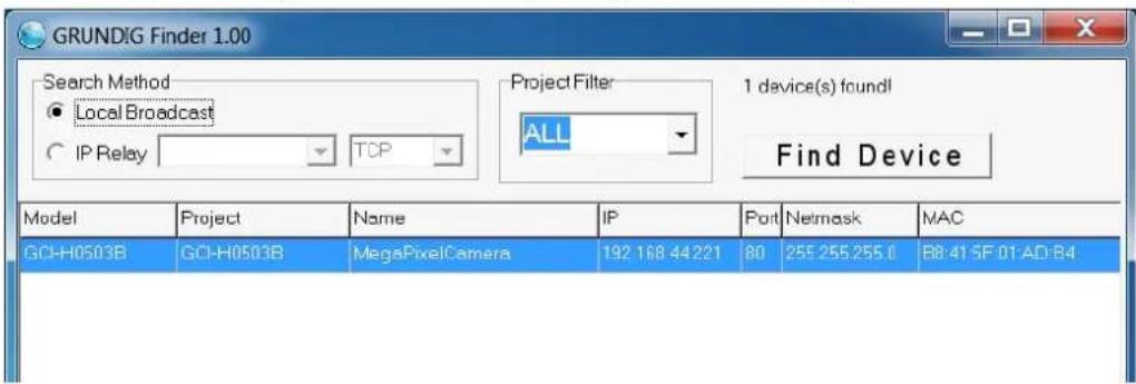
Step 4: Click on the "Find Device" button to search all the devices. Then select the IP Camera with the correct MAC address. After double-clicking on the IP Camera, the login window will appear.
Step 5: Enter User name and Password to access the IP Camera.
Installing the GRUNDIG Viewer Software Online :
For initial access to the IP Camera, a client program, GRUNDIG Viewer, will be automatically installed to your PC when connecting to the IP Camera.
If the Web browser does not allow the GRUNDIG Viewer installation, please check the Internet security settings or ActiveX controls and plug-ins settings (see 14. Internet Security Settings) to continue the process.
The Information Bar (just below the URL bar) may come out and ask for permission to install the ActiveX Control for displaying video in browser (see the picture below). Right-click on the Information Bar and select "Install ActiveX Control..." to allow the installation.

Then the security warning window will pop up. Click "Install" to carry on with the software installation.
Click on "Finish" to close the GRUNDIG Viewer window when download is finished. For detailed software download procedure, please refer to chapter 15. GRUNDIG Viewer Download Procedure.
NOTE: If the Live Video Pane on the Home Page cannot be shown to the users who have installed the GRUNDIG Viewer on the PC previously, please refer to the procedure in chapter 17. Delete the Existing GRUNDIG Viewer.
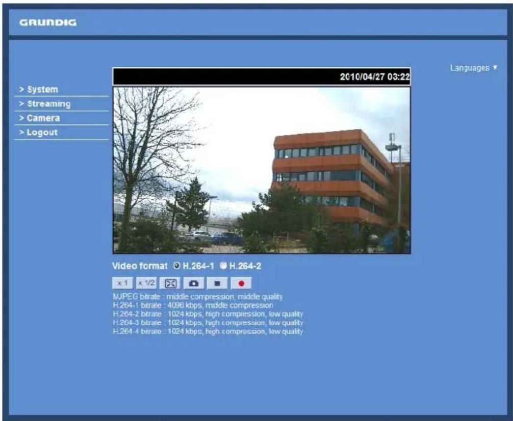
Once logged in to the IP Camera, users will see the Home page as shown below:
Administrator/User Privileges :
"Administrator" represents the person who can configure the IP Camera and who authorises users to have access to the camera; "User" refers to someone who has access to the camera with limited authority, i.e. to enter the Home and Camera setting pages.
Image and Focus Adjustment :
Adjust zoom and focus of the lens as necessary to produce a clear image. To set the correct angle of view and focus, you can use the BNC output on the camera. For this, please connect a PAL monitor to the BNC output.
6. Video Resolution Setup
The users can set up the Video Resolution on the Video Format page of the user-friendly browser-based configuration interface. The page "Video Format" can be found in the IP camera menu under the path:
Streaming > Video Format.
Under the Video Resolution section in the menu page "Video Format", please select your preferred resolution setting:
| H.264 + H.264 | |
| H.264-1 | H.264-2 |
| 1920 x 1080 (13fps) | 1920 x 1080 (13fps) |
| 1280 x 1024 (25fps) | |
| 1280 x 720 (25fps) | |
| 1024 x 768 (25fps) | |
| 800 x 600 (25fps) | |
| 1920 x 1080 (25fps) | 720 x 576 (25fps)* |
| 640 x 480 (25fps) | |
| 352 x 288 (25 fps) | |
| 1280 x 1024 (25fps) | 1280 x 1024 (13fps) |
| 1280 x 720 (25fps) | |
| 1024 x 768 (25fps) | |
| 800 x 600 (25fps) | |
| 720 x 576 (25fps) | |
| 640 x 480 (25fps) | |
| 352 x 288 (25fps) | |
| 1280 x 720 (25fps) | 1280 x 720 (25fps) |
| 1024 x 768 (25fps) | |
| 800 x 600 (25fps) | |
| 720 x 576 (25fps) | |
| 640 x 480 (25fps) | |
| 352 x 288 (25 fps) | |
| 1024 x 768 (25fps) | 1024 x 768 (25fps) |
| 800 x 600 (25fps) | |
| 720 x 576 (25fps) | |
| 640 x 480 (25fps) | |
| 352 x 288 (25fps) | |
| 800 x 600 (25fps) | 800 x 600 (25fps) |
| 720 x 576 (25fps) | |
| 640 x 480 (25fps) | |
| 352 x 288 (25fps) | |
| 720 x 576 (25fps) | 720 x 576 (25fps) |
| 640 x 480 (25fps) | |
| 352 x 288 (25fps) | |
| 640 x 480 (25fps) | 640 x 480 (25fps) |
| 352 x 288 (25fps) | |
| 352 x 288 (25fps) | 352 x 288 (25fps) |
| H.264 * MJPEG | |
| H.264 | MJPEG |
| 1920 x 1080 (13fps) | 1920 x 1080 (13fps) |
| 1280 x 1024 (25fps) | |
| 1280 x 720 (25fps) | |
| 1024 x 768 (25fps) | |
| 800 x 600 (25fps) | |
| 1920 x 1080 (25fps) | 720 x 576 (25fps) |
| 640 x 480 (25fps) | |
| 352 x 288 (25fps) | |
| 1280 x 1024 (25fps) | 1280 x 1024 (13fps) |
| 1280 x 720 (25fps) | |
| 1024 x 768 (25fps) | |
| 800 x 600 (25fps) | |
| 720 x 576 (25fps) | |
| 640 x 480 (25fps) | |
| 352 x 288 (25fps) | |
| 1280 x 720 (25fps) | 1280 x 720 (25fps) |
| 1024 x 768 (25fps) | |
| 800 x 600 (25fps) | |
| 720 x 576 (25fps) | |
| 640 x 480 (25fps) | |
| 352 x 288 (25FPS) | |
| 1024 x 768 (25fps) | 1024 x 768 (25fps) |
| 800 x 600 (25fps) | |
| 720 x 576 (25fps) | |
| 640 x 480 (25fps) | |
| 352 x 288 (25fps) | |
| 800 x 600 (25fps) | 800 x 600 (25fps) |
| 720 x 576 (25fps) | |
| 640 x 480 (25fps) | |
| 352 x 288 (25fps) | |
| 720 x 576 (25fps) | 720 x 576 (25fps) |
| 640 x 480 (25fps) | |
| 352 x 288 (25fps) | |
| 640 x 480 (25fps) | 640 x 480 (25fps) |
| 352 x 288 (25fps) | |
| 352 x 288 (25fps) | 352 x 288 (25fps) |
| MJPEG Only |
| MJPEG |
| 1920 x 1080 (25fps) |
| 1280 x 1024 (25fps) |
| 1280 x 720 (25fps) |
| 1024 x 768 (25fps) |
| 800 x 600 (25fps) |
| 720 x 576 (25fps) |
| 640 x 480 (25fps) |
| 352 x 288 (25fps) |
| H.264 Only |
| H.264 |
| 1920 x 1080 (25fps) Low Latency |
| 1920 x 1080 (25fps) |
| 1280 x 1024 (25fps) |
| 1280 x 720 (25fps) |
| 1024 x 768 (25fps) |
| 800 x 600 (25fps) |
| 720 x 576 (26fps) |
| 640 x 480 (25fps) |
| 352 x 288 (25fps) |
(*) Default
For more streaming combinations with several streams, please refer to "Streaming" > "Video Format" in the camera menu.
7. Browser-based Viewer Introduction
The picture below shows the Home page of the IP Camera's viewer window.
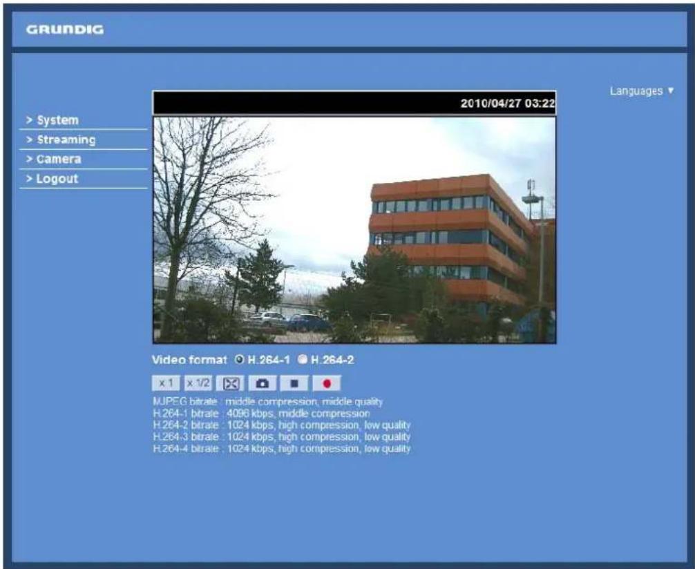
There are four tabs on the left (System, Streaming, Camera and Logout) and one tab on the right (Languages).
System setting :
The administrator can set host name, system time, admin password, network related settings, etc. Further details will be interpreted in chapter 9. System Related Settings.
Streaming setting :
The Administrator can configure a specific video resolution, video compression mode, video protocol, audio transmission mode, etc. in this page. Further details will be interpreted in chapter 10. Streaming Settings.
Camera setting :
Users can adjust various camera parameters. Further details will be interpreted in chapter 11. Camera Settings.
Logout :
Click on this tab to re-login to the IP Camera with another user name and password. Further details will be interpreted in chapter 12. Logout.
Languages :
Please choose one of the supported languages (German, English, French, Italian or Russian).
8. Home Page
In the Home page, there are several function buttons that are specified below.
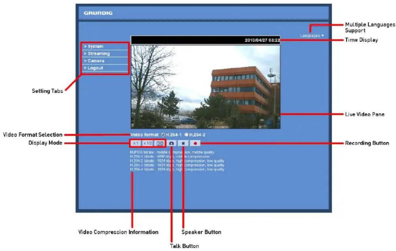
Display Mode (Screen Size Adjustment):
The display size of the image can be adjusted to x1/2 and full screen.
Snapshot button :
After pressing this button, the JPEG snapshots will automatically be saved in the appointed place. The default place of saving snapshots is: C:. For changing the storage location, please refer to section 9.13. 'File Location (on PC)' for further details.
NOTE: Users with the Windows 7 operating system on their PC need to follow the following procedure to be able to use the Snapshot function. First you need to log on to your computer as an Administrator. Then please go to Windows Start menu, click with the right mouse button on your Internet Browser and select in the appearing popup window "Run as Administrator". Afterwards you can log in to your camera as usual (as an administrator or user).
Video Streaming Pause/Restart button (pause/restart) :
If you click on the stop button to disable video streaming, the live video will be displayed as black. click on the restart button to show the live video again.
Recording button (on/off) :
When you click on this button, the recordings from the Live View will be saved to the location specified in the "File Location" page. The default storage location for the recording is: C:/. See section 9.13. 'File Location (on PC)' for further details.
NOTE: Users with Windows 7 operating system on their PC who want to use the Recording function, need to follow the procedure in the NOTE below the "Snapshot button" section in this chapter.
Multiple Languages Support :
Multiple languages are supported for the viewer window interface.
NOTE: The following functions are not available for the Browsers Firefox, Chrome, Safari and Opera: Full Screen Mode, Snapshot, Playback and Recording.
9. System Related Settings
The picture below shows all categories under the "System" tab. Each category in the left column will be explained in the following sections.
NOTE: The "System" configuration page is only accessible by the Administrator.
![GRUNDIG > System System Security Network DDNS Mail FTP HTTP Motion Detection Network failure detection Tampering Storage Management Recording File Location View information Factory Default Software Version Software Upgrade Maintenance < Back System Host name : MegaPixelCamera Time zone : GMT+00:00 Gambia, Liberia, Morocco, England Enable daylight saving time Time offset: 01:00:00 Start date: Jan 1st Sun Start time: 00:00:00 End date: Jan 1st Sun End time: 00:00:00 Sync with computer time PC date: 08/05/2012 [dd/mm/yyyy] PC time: 08:53:36 [hh:mm:ss] Manual Date: 01/04/2010 [dd/mm/yyyy] Time: 00:00:00 [hh:mm:ss] Sync with NTP server NTP server: 0.0.0.0 [host name or IP address] Update interval: Every hour Save](/content/2026/05/1039223/images/6d97e8487f027f8e1276d519079974670910427c242dfee6fe58ba65ae33a88c.jpg)
9.1. Host Name & System Time Setting
Click on the first category
![GRUNDIG > System System Security Network DDNS Mail FTP HTTP Motion Detection Network failure detection Tampering Storage Management Recording File Location View information Factory Default Software Version Software Upgrade Maintenance < Back System Host name : MegaPixelCamera Time zone : GMT+00:00 Gambia, Liberia, Morocco, England Enable daylight saving time Time offset: 01:00:00 Start date: Jan 1st Sun Start time: 00:00:00 End date: Jan 1st Sun End time: 00:00:00 Sync with computer time PC date: 08/05/2012 [dd/mm/yyyy] PC time: 08:53:36 [hh:mm:ss] Manual Date: 01/04/2010 [dd/mm/yyyy] Time: 00:00:00 [hh:mm:ss] Sync with NTP server NTP server: 0.0.0.0 [host name or IP address] Update interval: Every hour Save](/content/2026/05/1039223/images/3736c4b60d57e95f29faf0a02bb56d23b82475dc9656f98cd7384b2b239199e7.jpg)
Host Name :
The name is for camera identification (max. 30 characters). If an alarm function is enabled and is set to send an alarm message by Mail/FTP, the host name entered here will be displayed in the alarm message.
Time Zone :
Select the time zone you are in from the drop-down menu.
Enable Daylight Saving Time :
To enable DST, please check the item and then specify the time offset and DST duration. The format for time offset is [hh:mm:ss]; for instance, if the amount of time offset is one hour, please enter "01:00:00" into the field.
Sync with Computer Time :
After selecting this item, the video date and time display will be synchronised with the PC.
Manual :
The Administrator can set the date, time and day manually. Entry format should be identical with the format shown next to the enter fields.
Sync with NTP server :
Network Time Protocol (NTP) is an alternative way to synchronise your camera's clock with a NTP server. Please specify the server you wish to synchronise the camera with in the enter field. Then select an update interval from the drop-down menu. For further information about NTP, please see the web site: www.ntp.org.
NOTE: Click on < Save > to confirm the new setting.
9.2. Security
When you click on the category
When you click on the
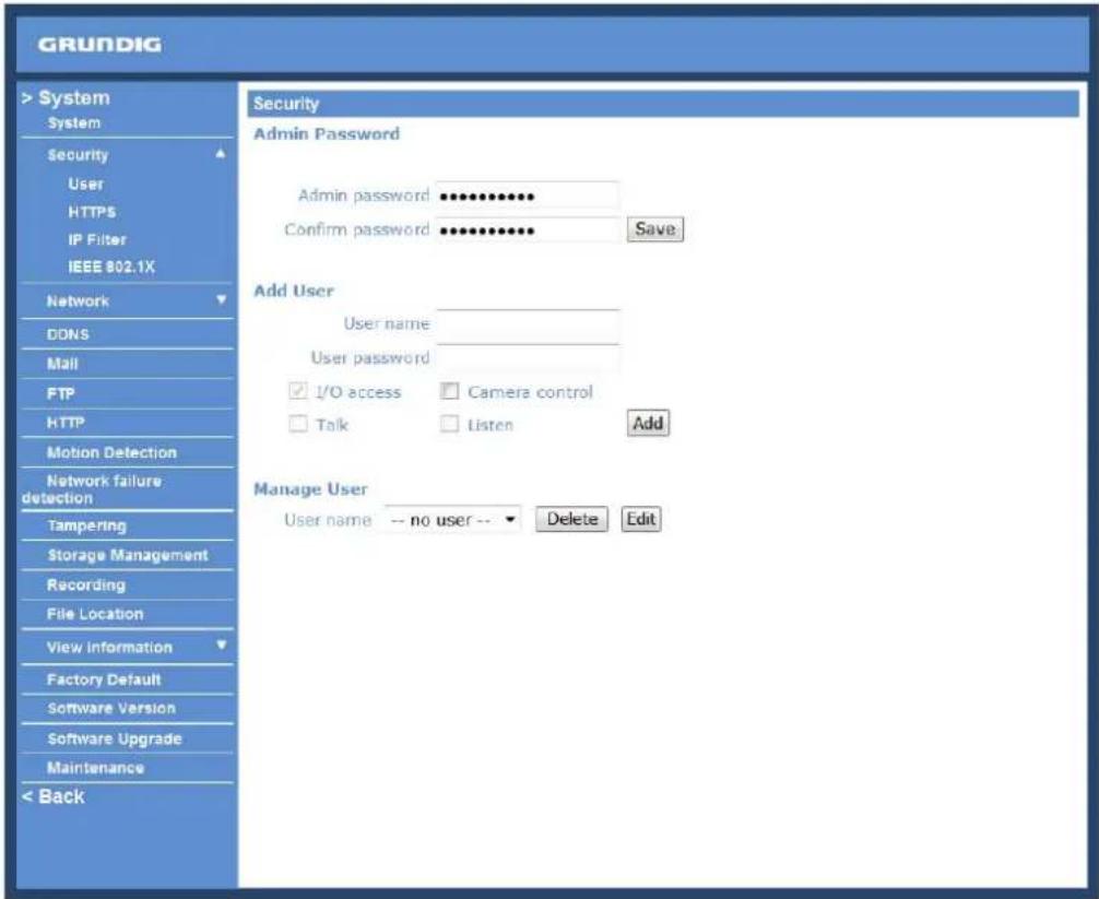
Admin Password :
Change the administrator's password by putting in the new password in both text boxes. The input characters/numbers will be displayed as dots for security purposes. After clicking
NOTE: The following characters are valid: A-Z, a-z, 0-9, !#\$%&'-.@^\~.
Add User :
Type in the new user name and password and click
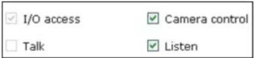
- I/O access:
This item supports fundamental functions that enable users to view the video when accessing the camera.
- Camera control:
This item allows the specified User to change the camera's parameters on the Camera Setting page.
- Talk/Listen:
Talk and Listen functions allow the appointed user on the local site (PC site) to communicate, for instance, with the administrator on the remote site.
Manage User :
To delete a user, pull down the user list, and select the user name you wish to delete. Then click
To edit a user, pull down the user list and select a user name. Click
NOTE: It is required to enter the User password and to select the functions that will be open to the user. When finished, click
![http://192.168.7.123/lang1/server_editaccount..... http://192.168.7.123/lang1/server_editaccount.html User name [user] User password ••••• ✓ I/O access ✓ Camera control ✓ Talk ✓ Listen Save Close Don Internet 100%](/content/2026/05/1039223/images/997047c6d108d8c420bedaf5c1486b82fa9e145942a5b26ef56e707e65232b02.jpg)
After clicking on the
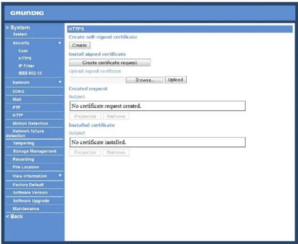
To use HTTPS on the IP Camera, a HTTPS certificate must be installed. The HTTPS certificate can be obtained by either creating and sending a certificate request to a Certificate Authority (CA) or creating a self-signed HTTPS certificate, as described below.
Create self-signed certificate :
Before a CA-issued certificate is obtained, users can create and install a self-signed certificate first.
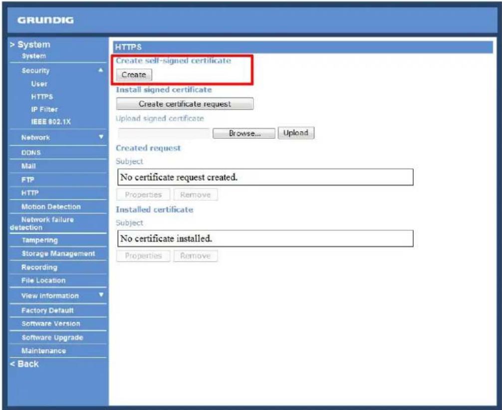
Click on the
NOTE: The self-signed certificate does not provide the same high level of security as when using a CA-issued certificate.
Provide the requested information in the Create Dialog. Please refer to the section "Provide the Certificate Information" for more details.
Install signed certificate :
Click on the "Create Certificate Request" button to create and submit a certificate request in order to obtain a signed certificate from the CA (Certificate Authority).
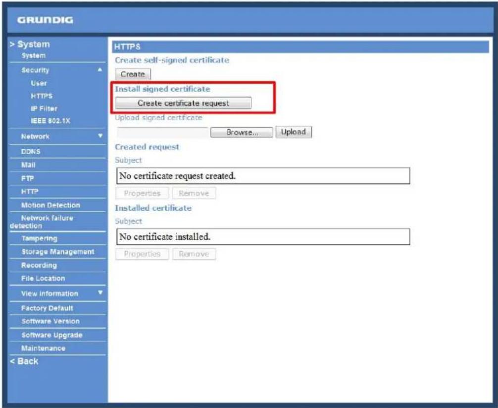
When the request is complete, the subject of the Created Request will be shown in the field. Click "Properties" below the Subject field, copy the PEM-formatted request and send it to your selected CA.
When the signed certificate is returned, install it by uploading the signed certificate.
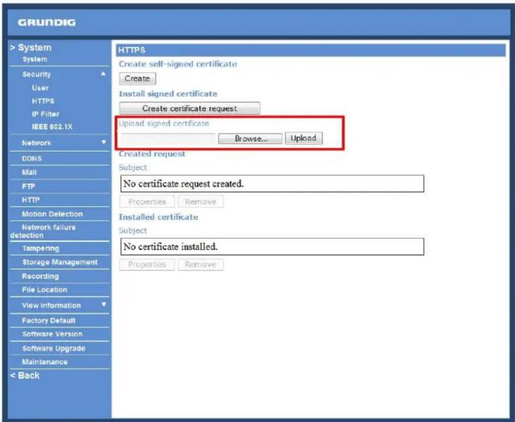
Provide the Certificate Information :
To create a Self-signed HTTPS Certificate or a Certificate Request to CA, please enter the information as requested:
![http://192.168.44.19/lang1/server_certificate.html - Windows Internet Explorer http://192.168.44.19/lang1/server_certificate.html Create Self-Signed Certificate Country: State or province: Locality: Organisation: Organisational unit: Common name: Valid days: 365 days[1...9999] OK Cancel](/content/2026/05/1039223/images/709d5a0d35ec9cb3c917f32cbeb6f8ac972c43551af497d0ac234e72960c604f.jpg)
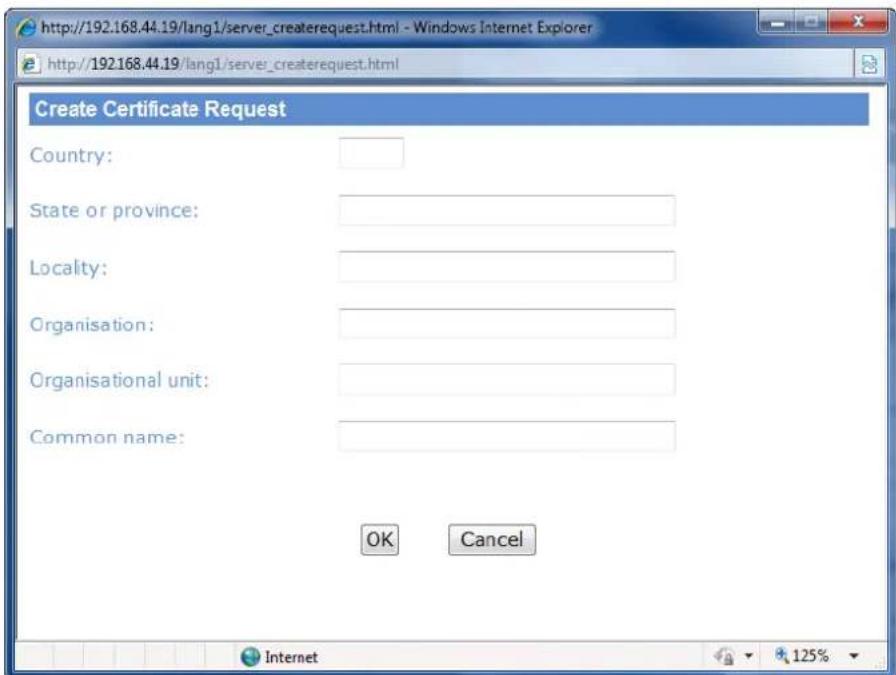
- Country:
Enter a 2-letter combination code to indicate the country the certificate will be used in. For instance, type in "GB" to indicate Great Britain.
- State or province:
Enter the local administrative region.
- Locality:
Enter other geographical information.
- Organisation:
Enter the name of the organisation to which the entity identified in "Common Name" belongs.
- Organisation Unit:
Enter the name of the organisational unit to which the entity identified in "Common Name" belongs.
- Common Name:
Indicate the name of the person or other entity that the certificate identifies (often used to identify the website).
- Valid days (Self-signed Certificate Only):
Enter the period in days (1\~9999) to indicate the valid period of the certificate.
Click "OK" to save the Certificate Information after completing.
When using the IP filter, access to the IP Camera can be restricted by denying/allowing specific IP addresses.
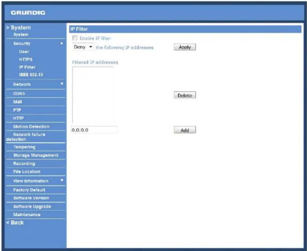
General :
- Enable IP Filter:
Check the box to enable the IP Filter function. Once enabled, access to the IP Camera will be allowed/denied for the listed IP addresses (IPv4).
Select "Allow" or "Deny" from the drop-down list and click the
- Add/Delete IP Address:
Input the IP address and click the
The Filtered IP Addresses list box shows the currently configured IP addresses. Up to 256 IP address entries may be specified.
To remove an IP address from the list, please select the IP and then click the
The IP Camera can access a network protected by 802.1X/EAPOL (Extensible Authentication Protocol over LAN). To do this, users need to contact the network administrator to receive certificates, user IDs and passwords.
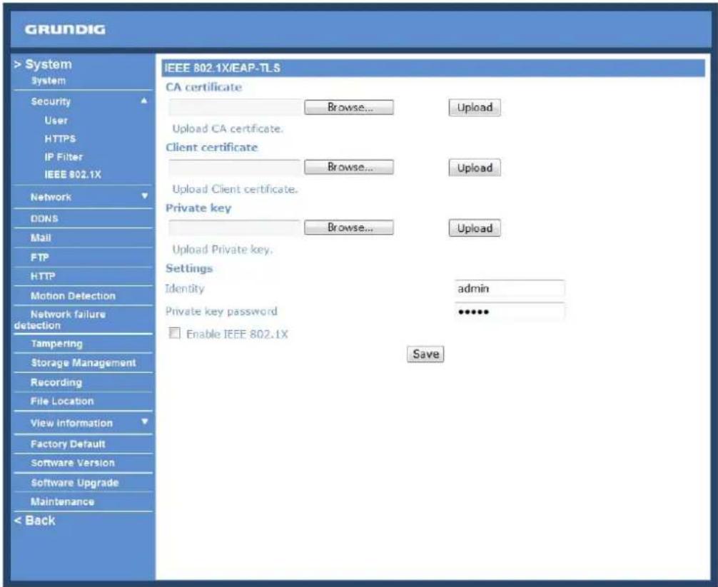
CA Certificate :
The CA certificate is created by the Certification Authority for the purpose of validating itself. Upload the certificate for checking the server's identity.
Client Certificate/Private Key :
Upload the Client Certificate and Private Key for authenticating the IP Camera itself.
Settings :
- Identity:
Enter the user identity associated with the certificate. Up to 16 characters can be used.
- Private Key Password:
Enter the password (maximum 16 characters) for your user identification.
Enable IEEE 802.1X :
Check the box to enable IEEE 802.1X.
Click "Save" to save the IEEE 802.1X/ EAP—TLS setting.
9.3. Network
When you click on the category
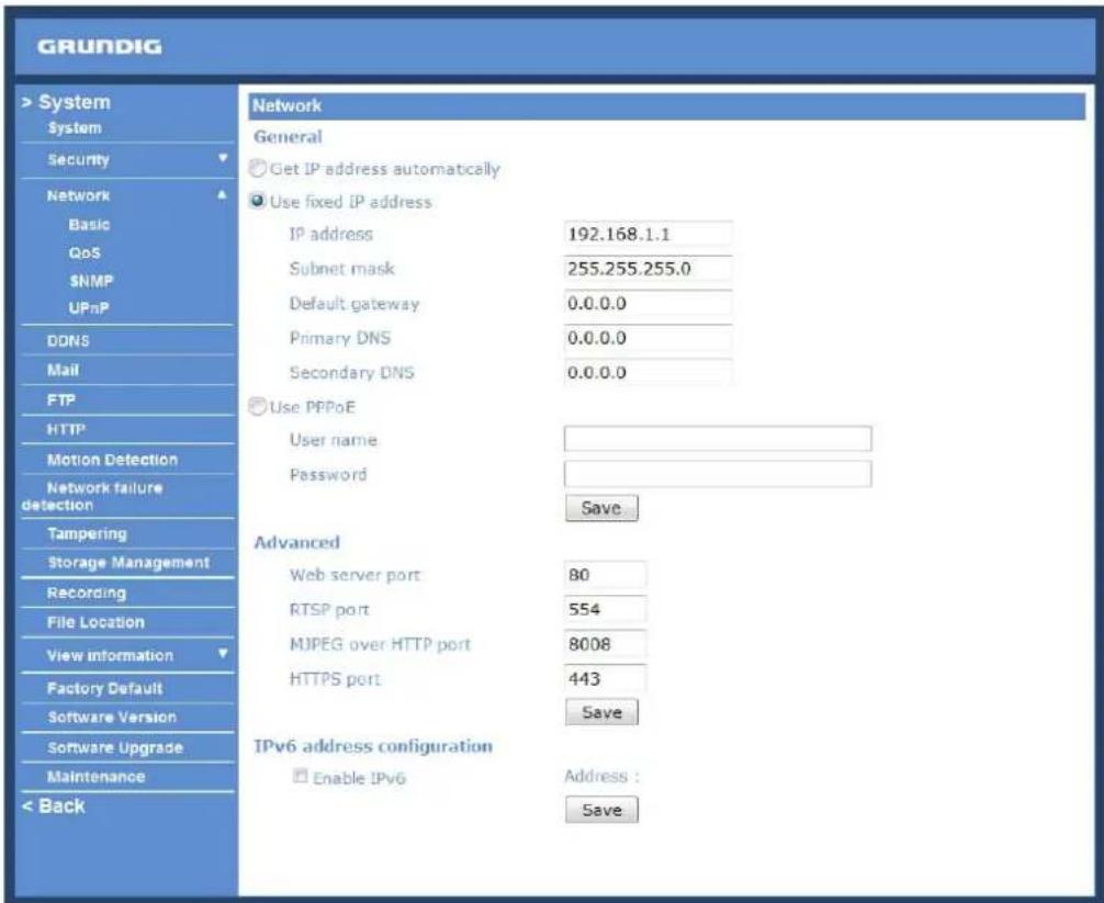
Users can choose to connect to the IP Camera through a fixed or dynamic (DHCP) IP address. The IP Camera also provides PPPoE (Point-to-Point Protocol over Ethernet) support for users who connect to the network via PPPoE.
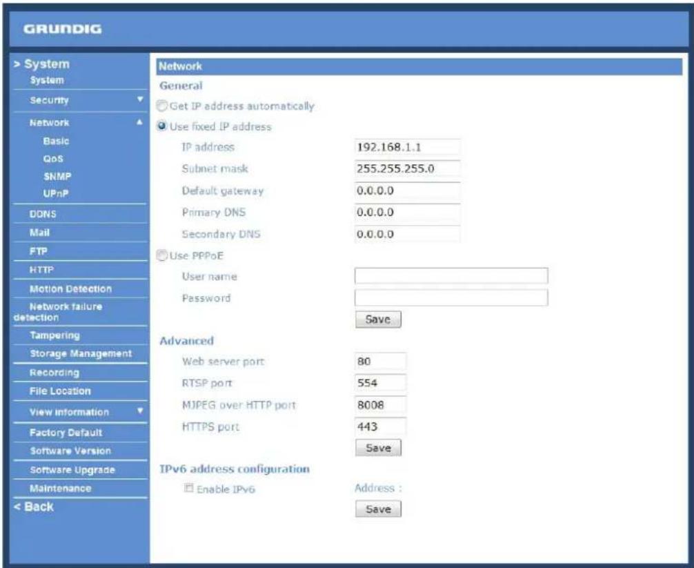
Get IP address automatically (DHCP):
The camera's default setting is "Use fixed IP address". Please refer to the previous section 6. Accessing the Camera for login with the default IP address.
If "Get IP address automatically" is selected, after the IP Camera restarts, users can search the IP address through the installer program "GRUNDIG Finder.exe", that is on the supplied CD.
NOTE: The DHCP function can only be used if you have a DHCP server in the used network.
NOTE: Please make a record of the IP Camera's MAC address, which can be found on the label of the camera, for identification in the future.
Use a fixed IP address :
To set up a static IP address, select "Use fixed IP address" and move the cursor to the IP address blank (as indicated below) and insert the new IP address, e.g. 192.168.44.230; then go to Default Gateway (explained later) and type in the appropriate setting, e.g. 192.168.44.1. Click on "Save" to confirm the new setting.
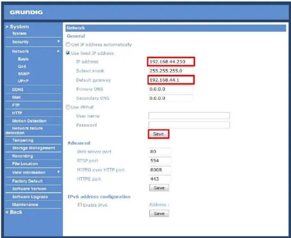
When using a static IP address to login to the IP Camera, users can access it either through the "GRUNDIG Finder" software (see 6. Accessing the Camera) or input the IP address in the URL bar and click on "Enter".

- IP address:
This is necessary for network identification.
- Subnet mask:
It is used to determine if the destination is in the same subnet. The default value is "255.255.255.0".
- Default gateway:
This is the gateway used to forward frames to destinations in different subnets. An invalid gateway setting will fail in the transmission to destinations in different subnets.
- Primary DNS:
Primary DNS is the primary domain name server that translates hostnames into IP addresses.
- Secondary DNS:
Secondary DNS is a secondary domain name server that backs up the primary DNS.
Use PPPoE :
The PPPoE users need to enter the PPPoE Username and Password into the fields, and need to click on the "Save" button to complete the setting.
Advanced :
- Web Server port:
The default web server port is 80. Once the port is changed, all users must be informed about the change for the connection to be successful. For instance, when the Administrator changes the HTTP port of the IP Camera which has the IP address "192.168.0.100" from 80 to 8080, the users must type in in the web browser "http://192.168.0.100:8080" instead of "http://192.168.0.100".
- RTSP port:
The default setting of the RTSP Port is 554; the setting range is from 1024 to 65535.
- MJPEG over HTTP port:
The default setting of the MJPEG over HTTP Port is 8008; the setting range is from 1024 to 65535.
- HTTPS port:
The default setting of the HTTPS Port is 443; the setting range is from 1024 to 65535.
NOTE: Be aware to assign a different port number for each separate service mentioned above.
IPv6 Address Configuration :
With IPv6 support, users can use the corresponding IPv6 address for browsing. Enable IPv6 by checking the box and click "Save" to complete the setting.
QoS allows providing differentiated service levels for different types of traffic packets which guarantees delivery of priority services especially when network congestion occurs. Adapting the Differentiated Services (DiffServ) model, traffic flows are classified and marked with DSCP (DiffServ Codepoint) values, and thus receive the corresponding forwarding treatment from DiffServ capable routers.
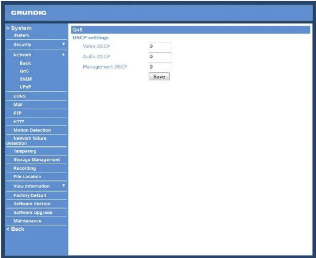
DSCP Settings :
The DSCP value range is from 0 to 63. The default DSCP value is 0, which means that DSCP is disabled.
The IP Camera uses the following QoS Classes: Video, Audio and Management.
- Video DSCP:
This class consists of applications such as MJPEG over HTTP, RTP/RTSP and RTSP/HTTP.
- Audio DSCP:
This setting is only available for the IP Cameras which support audio.
- Management DSCP:
This class consists of the HTTP traffic: Web browsing.
Click the "Save" button to complete the setting.
NOTE: To enable this function, please make sure the switches/routers in the network support QoS.
With Simple Network Management Protocol (SNMP) support, the IP Camera can be monitored and managed remotely by the network management system.
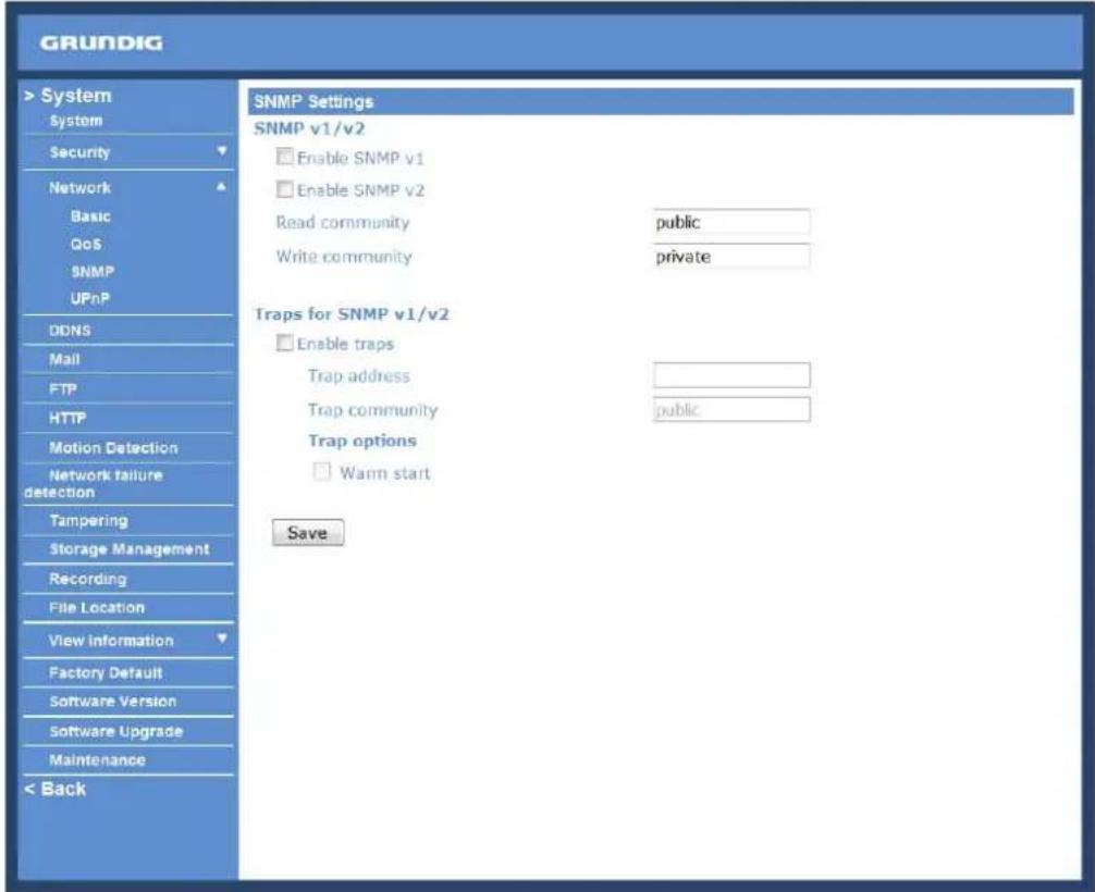
SNMP v1/v2 :
- Enable SNMP:
Select the version of SNMP to use by checking the corresponding box.
- Read Community:
Specify the community name which has read-only access to all supported SNMP objects. The default value is "public".
- Write Community:
Specify the community name which has read/write access to all supported SNMP objects (except read-only objects). The default value is "private".
Traps for SNMP v1/v2 :
Traps are used by the IP Camera to send messages to a management system about important events or status changes.
- Enable Traps:
Check the box to activate trap reporting.
- Trap address:
Enter the IP address of the management server.
- Trap community:
Enter the community to use when sending a trap message to the management system.
Trap option :
- Warm start:
A Warm start SNMP trap signifies that the SNMP device, i.e. the IP Camera, performs a software reload.
Click the "Save" button to complete the setting.
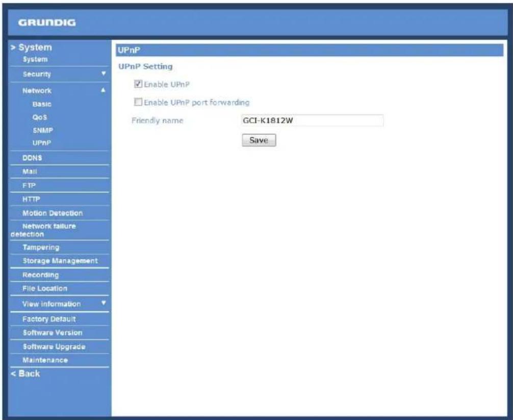
UPnP Setting :
- Enable UPnP:
When UPnP is enabled, whenever the IP Camera is presented to LAN, the icon of the connected IP Cameras will appear in My Network Places to allow for direct access as shown below.
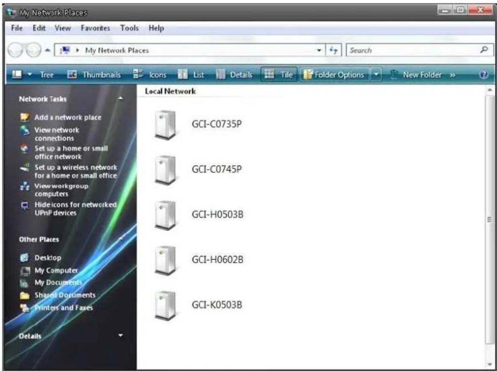
NOTE: To enable this function, please make sure the UPnP component is installed on your computer. Please refer to chapter 16. Install UPnP Components for UPnP component installation procedure.
- Enable UPnP port forwarding:
When UPnP port forwarding is enabled, the IP Camera is allowed to open the web server port on the router automatically.
NOTE: To enable this function, please make sure that your router supports UPnP and is activated.
- Friendly name:
Set the name of the IP Camera for identification.
9.4.DDNS
The Dynamic Domain Name System (DDNS) allows a host name to be constantly synchronised with a dynamic IP address. In other words, it allows those using a dynamic IP address to be associated to a static domain name so that others can connect to it through this name.
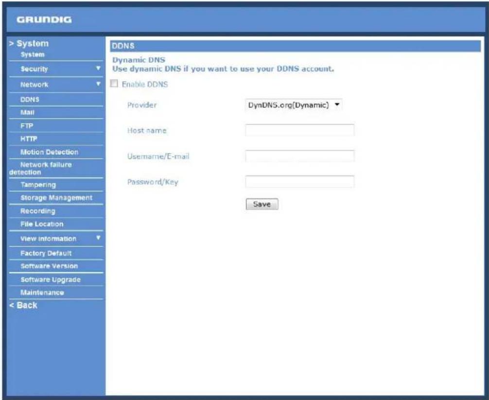
Enable DDNS :
Check the item to enable DDNS.
Provider :
Select one DDNS host from the provider list.
Host name :
Enter the registered domain name in the field.
Username/E-mail :
Enter the user name or e-mail required by the DDNS provider for authentication.
Password/Key :
Enter the password or key required by the DDNS provider for authentication.
9.5. Mail
The Administrator can can set up the sending of an e-mail via Simple Mail Transfer Protocol [SMTP] when a motion is detected. SMTP is a protocol for sending e-mail messages from server to server. SMTP is a relatively simple, text-based protocol, where one or more recipients of a message are specified and to whom the message text is transferred. The configuration page is shown below:
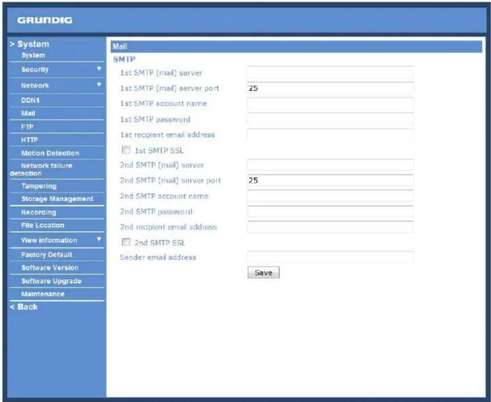
Two sets of SMTP can be configured. Each set includes the SMTP Server, Account Name, Password and E-mail Address settings. Concerning the SMTP server, contact your network service provider for more specific information.
Click the "Save" button to save the changes.
9.6.FTP
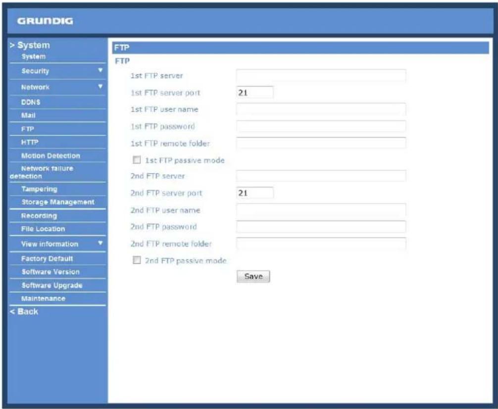
The Administrator can set the sending of alarm messages to a specific File Transfer Protocol (FTP) site when motion is detected. Users can assign an alarm message to up to two FTP sites. The FTP setting page is shown below. Enter the FTP details, which include server, server port, user name, password and remote folder, into the fields.
Click "Save" when the setting is finished.
9.7. HTTP
A HTTP Notification server can listen for notification messages from IP Cameras by triggered events. The HTTP setting page is shown below. Enter the HTTP details, which include the server name (for instance, http://192.168.1.1/admin.php), user name, and password into the fields.
Click "Save" when the setting is finished.
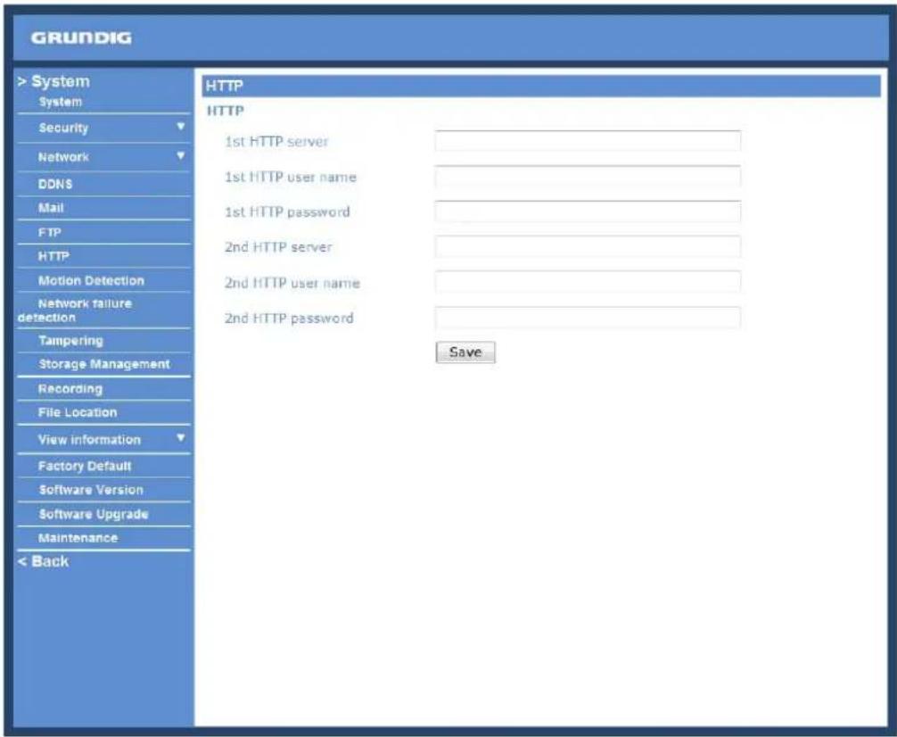
Please refer to: 9.8. Motion Detection for HTTP Notification settings.
9.8. Motion Detection
The Motion Detection function allows detecting suspicious motion and triggers alarms when motion volume in the detected area reaches/exceeds the determined sensitivity threshold value.
![GRUNDIG > System System Security Network DDNS Mail FTP HTTP Motion Detection Network failure detection Tampering Storage Management Recording File Location View Information Factory Default Software Version Software Upgrade Maintenance < Back Motion Detection Motion Detection Off On Motion Detection Setting Sampling pixel interval [1-10] 1 Detection level [1-100] 10 Sensitivity level [1-100] 80 Time interval(sec) [0-7200] 10 Triggered Action Record stream to sd card Send alarm message by FTP Upload image by FTP Send HTTP notification Motion Detection Windows add delete Send alarm message by E-mail Upload Image by E-Mail File Name : image.jpg Add date/time suffix Add sequence number suffix (no maximum value) Add sequence number suffix up to 0 and then start over Overwrite save](/content/2026/05/1039223/images/8408a0ae74ab84847ba8c100344bd8be4ff198508226d639b78e3c368afea034.jpg)
In the Motion Detection setting page a frame (Motion Detection Window) is displayed in the Live View Pane. The Motion Detection Window is for defining the motion detection area. To change the size of the Motion Detection Window, move the mouse cursor to the edge of the frame and draw it outward/inward. When you move the mouse cursor to the center of the frame and hold the click, you can shift the frame to the intended location.
Up to 10 Motion Detection Windows can be set. click on the "Add" button under the Live View Pane to add a Motion Detection Window. To delete a Motion Detection Window, move the mouse cursor to the selected Window, and click on the "Delete" button.
If the Motion Detection function is activated, a pop-up window (Motion) with motion indication will be shown.
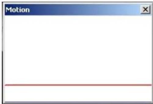
When a motion is detected, the signals will be displayed in the Motion window as shown below:
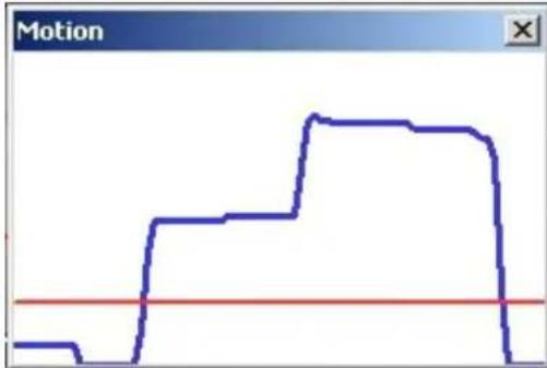
line
| Motion Level | Value | | ------------ | ----- | | Start | 0 | | Mid | 1 | | Peak | 3 | | End | 0 |The detailed settings of Motion Detection are described as follows:
Motion Detection :
You will be able to turn the Motion Detection on/off in the System section "Motion Detection". The default setting is: Off.
Motion Detection Setting :
Users can adjust various parameters of Motion Detection in this section.
- Sampling pixel interval [1-10]:
The default value is 1. If the value is set as 3, it means that within the detection region, the system will take one sampling pixel for every 3 pixels by each row and each column (please refer to the figure below).
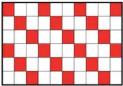
natural_image
Checkerboard pattern with alternating red and white squares (no text or symbols)- Detection level [1-100]:
The default level is 10. This item is to set the detection level for each sampling pixel; the smaller the value, the more sensitive the detection is.
- Sensitivity level [1-100]:
The default level is 80, which means if 20% or more sampling pixels are detected as changing, the system will detect motion. The bigger the value, the more sensitive the detection is. Meanwhile, when the value is bigger, the red horizontal line in the motion indication window will be accordingly lower.
- Time interval (sec) [0-7200]:
The default interval is 10. This value is the interval between each detected motion.
Triggered Action (Multi-option) :
The Administrator can specify alarm actions that will take place when the alarm is triggered. All options are listed as follows:
- Record Stream to SD Card:
When you select this item, the Motion Detection recording will be stored on your Micro SD/SDHC card when motion is detected.
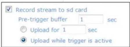
The pre-trigger buffer recording function allows users to check what happened to trigger the alarm. The pre-trigger buffer time range is from 1 to 3 seconds.
Select
Select
NOTE: Please make sure the local recording (with Micro SD/SDHC card) is activated so that this function can be implemented. See section 9.12. 'Recording (on Camera)' for further details.
- Send Alarm Message by FTP:
The Administrator can choose to send an alarm message by FTP when a motion is detected.
- Send Alarm Message by E-Mail:
The Administrator can choose to send an alarm message by E-Mail when a motion is detected.
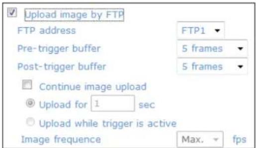
- Upload Image by FTP:
After selecting this item, the Administrator can assign a FTP site and configure various parameters as shown in the picture below. When a motion is detected, event images will be uploaded to the appointed FTP site.
The
On the other hand, the
Check the box
- Select
- Select
Set the Image frequency as the upload frame rate. The setting range is from 1 frame to 15 frames.
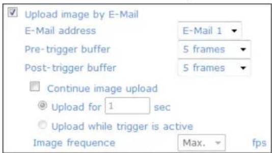
- Upload Image by E-Mail:
After selecting this item, the Administrator can assign an e-mail address and configure various parameters as shown in the picture below. When a motion is detected, event images will be sent to the appointed e-mail address.
The
On the other hand, the
Check the box
- Select
and enter the duration in the blank. The images of the duration will be uploaded to the FTP when the alarm input is triggered. The setting range is from 1 to 9999 seconds. - Select
to keep the images being uploaded to the FTP while the trigger is active, i.e. until the alarm is stopped.
Set the Image frequency as the upload frame rate. The setting range is from 1 frame to 15 frames.
NOTE: Make sure SMTP or FTP configuration has been completed. See section 9.5. Mail and 9.6. FTP for further details.
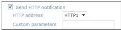
- Send HTTP notification:
Check this item, select the destination HTTP address, and specify the parameters for event notifications when
For instance, if the custom parameter is set as "action=1&group=2", and the HTTP server's name is "http://192.168.1.200/admin.php", the notification will be sent to the HTTP server as "http://192.168.1.200/admin.php?Action=1&group=2" when an alarm is triggered.
File Name :
Enter a file name into the blank box, e.g. image.jpg. The uploaded image's file name format can be set in this section. Please select the one that meets your requirements.
- Add date/time suffix:
File name: imageYYMMDD_HHNNSS_XX.jpg
Y: Year, M: Month, D: Day
H: Hour, N: Minute, S: Second
X: Sequence Number
- Add sequence number suffix (no maximum value):
File name: imageXXXXXXXX.jpg
X: Sequence Number
- Add sequence number suffix up to _ and then start over:
File Name: imageXX.jpg
X: Sequence Number
The file name suffix will end at the number being set. For example, if the setting is "10", the file name will start from 00, end at 10, and then start all over again.
- Overwrite:
The original image in the FTP site will be overwritten with a static filename by the new uploaded file.
Save :
Click on the "Save" button to save all the Motion Detection alarm settings mentioned above.
9.9. Network Failure Detection
This function is used to detect network failure that might happen during camera operation.
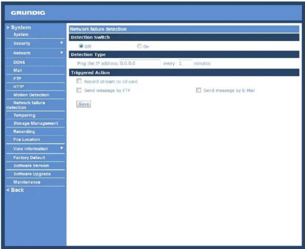
Detection Switch :
Here you can turn the Network Failure Detection on and off.
Detection Type :
Here you can set an IP address that should be pinged in order to detect network failure. Please also set the interval (in minutes) for this pinging.
Triggered Action (Multi-option):
The Administrator can specify alarm actions that will take place when motion is detected. All options are listed as follows:
- Record Stream to SD Card:
When you check this item, the alarm-triggered recording will be stored on your Micro SD/SDHC card when Network Failure is detected.
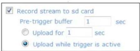
The pre-trigger buffer recording function allows users to check what happened to trigger the alarm. The pre-trigger buffer time range is from 1 to 3 seconds.
Select
Select
NOTE: Please make sure the local recording (with Micro SD/SDHC card) is activated so that this function can be implemented. See section 9.12. 'Recording (on Camera)' for further details.
- Send Alarm Message by FTP:
The Administrator can select whether to send an alarm message by FTP when Network Failure is detected.
- Send Alarm Message by E-Mail:
The Administrator can choose to send an alarm message by E-Mail when Network Failure is detected.
9.10. Tampering
The Tampering Alarm function helps the IP Camera against tampering such as deliberate redirection, blocking, spray paint, lens covering, etc. through video analysis and reaction to such events by sending out notifications or uploading snapshots to the specified destination(s).
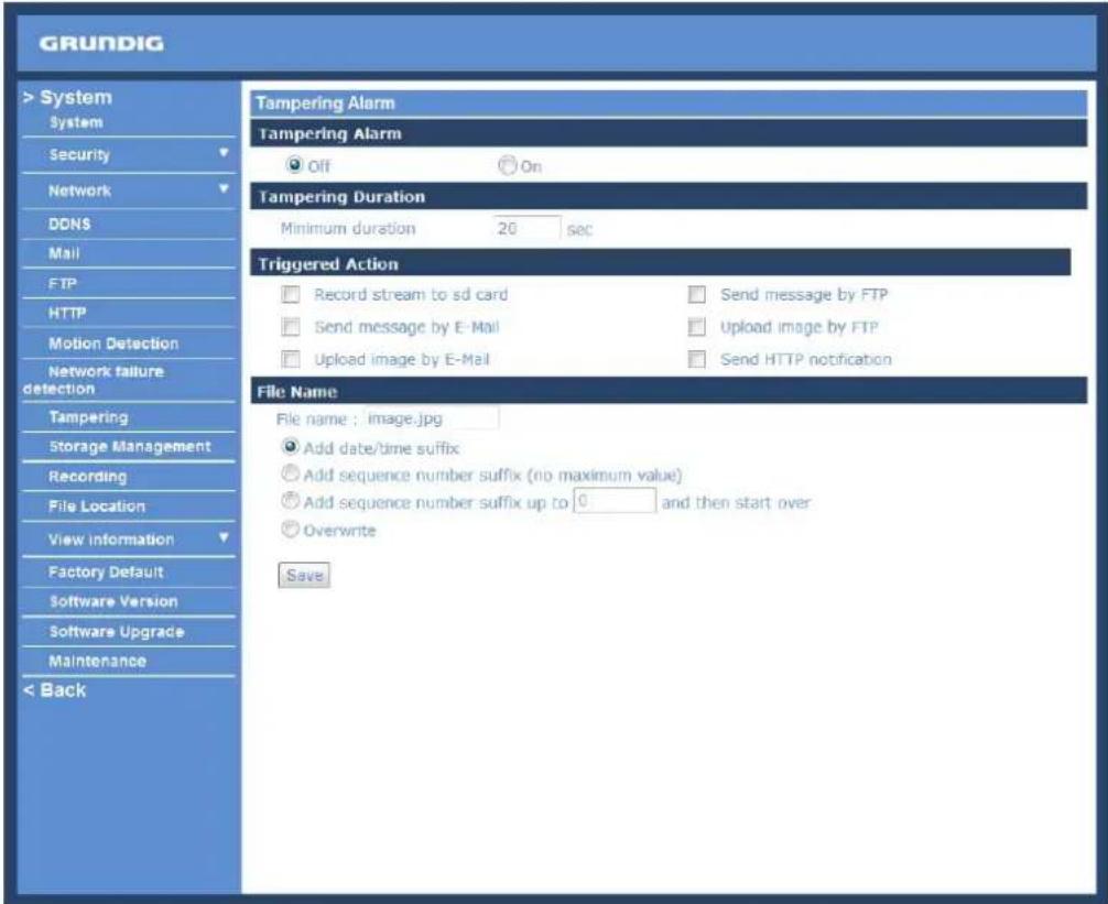
Detection of camera tampering is achieved by measuring the differences between the older frames of video (which are stored in buffers) and more recent frames.
Tampering Alarm :
You will be able to turn the Tampering Alarm function on/off in the Tampering Alarm setting section. The default setting is: Off.
Tampering Duration :
The Minimum Tampering Duration is the time the video analysis will need to determine whether any camera tampering has occurred. Defining the Minimum Duration can also be interpreted as defining the Tampering threshold; longer duration represents a higher threshold. The settable Tampering Duration time range is from 10 to 3600 seconds.
Triggered Action (Multi-option):
The Administrator can specify alarm actions that will take place when tampering is detected. All options are listed as follows:
- Record Stream to SD Card:
When you check this item, the alarm-triggered recording will be stored on your Micro SD/SDHC card when Tampering is detected.
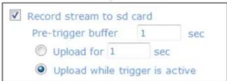
The pre-trigger buffer recording function allows users to check what happened to trigger the alarm. The pre-trigger buffer time range is from 1 to 3 seconds.
Select
Select
NOTE: Please make sure the local recording (with Micro SD/SDHC card) is activated so that this function can be implemented. See section 9.12. 'Recording (on Camera)' for further details.
- Send Alarm Message by FTP:
The Administrator can select whether to send an alarm message by FTP when Tampering is detected.
- Send Alarm Message by E-Mail:
The Administrator can choose to send an alarm message by E-Mail when Tampering is detected.
- Upload Image by FTP:
After selecting this item, the Administrator can assign a FTP site and configure various parameters as shown in the figure below. When tampering is detected, event images will be uploaded to the appointed FTP site.
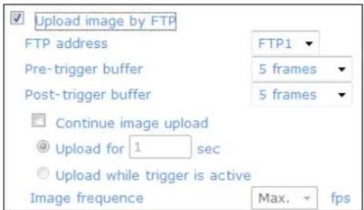
The
On the other hand, the
Check the box
- Select
- Select
Set the Image frequency as the upload frame rate. The setting range is from 1 frame to 15 frames.
- Upload Image by E-Mail:
After selecting this item, the Administrator can assign an e-mail address and configure various parameters as shown in the figure below. When tampering is detected, event images will be sent to the appointed e-mail address.
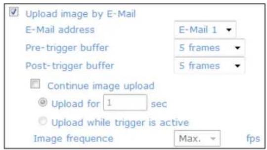
The
On the other hand, the
Check the box
- Select
- Select
Set the Image frequency as the upload frame rate. The setting range is from 1 frame to 15 frames.
NOTE: Make sure SMTP or FTP configuration has been completed. See section 9.5. Mail and 9.6. FTP for further details.
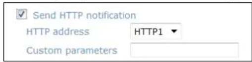
- Send HTTP notification:
Check this item, select the destination HTTP address, and specify the parameters for HTTP notifications. When the Tampering Alarm is triggered, the HTTP notifications can be sent to the specified HTTP server.
For instance, if the custom parameter is set as "action=1&group=2", and the HTTP server's name is "http://192.168.1.200/admin.php", the notification will be sent to the HTTP server as "http://192.168.1.200/admin.php?Action=1&group=2" when an alarm is triggered.
File Name :
The uploaded image's filename format can be set in this section. Please select the one that meets your requirements (please see the section "File Name" in 9.8. Motion Detection).
Save :
Click the Save button to save all the Tampering Alarm settings mentioned above.
9.11. Storage Management (on Camera)
Users can store local recordings on a Micro SD/SDHC card of up to 32 GB. This page shows the capacity information of the Micro SD card and a recording list with all the recording files saved on the memory card. Users can also format the SD card and implement automatic recording cleanup through the setting page.
To implement Micro SD card recording, please go to the "Recording" page (see 9.12. 'Recording [on Camera]') for activation.
NOTE: Please format the Micro SD/SDHC card when using it for the first time. Formatting will also be required when a memory card has already been used on one device and was later transferred to another device with a different software platform.
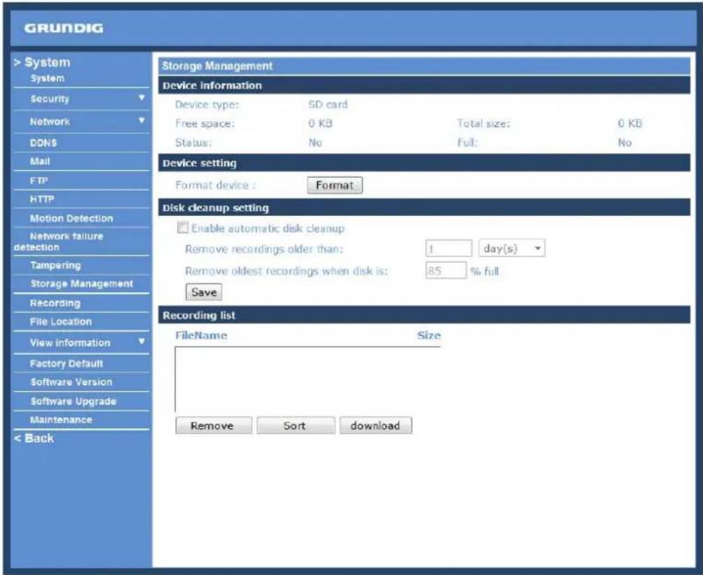
Device Information :
When users insert the Micro SD/SDHC card, the card information such as the memory capacity and status will be shown in the Device Information section. The memory card is successfully installed if its status is shown in the "Device information" section in the Storage Management page.
Device Setting :
Click on the "Format" button to format the memory card.
Disk Cleanup Setting :
Users can enable an automatic recordings cleanup by checking this item and specifying the time and storage limits.
Recording List :
Each video file on the Micro SD/SDHC card will be listed in the Recording list as shown below. The maximum file size is 60 MB (60 MB per file).
If the recording modus is set to "Always" and at the same time the event recording (when a motion detection or an alarm takes place) is also turned on, in this case, when an event occurs, the event will be recorded first, afterwards the camera will return to normal recording mode.
When the recording mode is set to "Always" (consecutive recording) in the submenu "Recording" and the Micro SD/SDHC card recording is also allowed to be enabled when triggered by events, once the events occur, the system will immediately implement the recorded events to the memory card. After event recording, the device will return to regular recording mode.
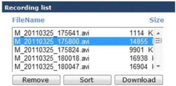
- Remove:
To remove a file, select the file first, and then click on the "Remove" button.
- Sort:
When you click on the "Sort" button, the files in the Recording list will be listed in name and date order.
NOTE: The capital letters (A, M or R) appearing in the very beginning of a name denote the sort of the recording: A stands for Alarm, M stands for Motion and R stands for regular recording.
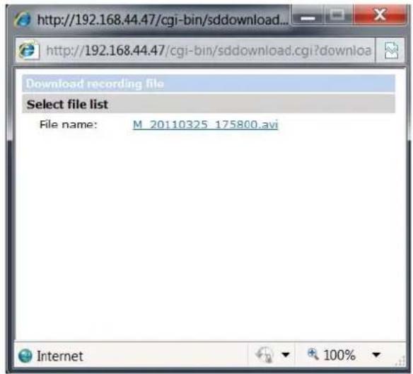
- Download:
To open/download a video clip, select the file first, and then click on the "Download" button underneath the Recording list field. The selected file window will pop up as shown below. Click on the AVI file to directly play the video in the player or download it to a specified location.
9.12. Recording (on Camera)
In the Recording setting page, users can specify the recording schedule that fits the present surveillance requirement.
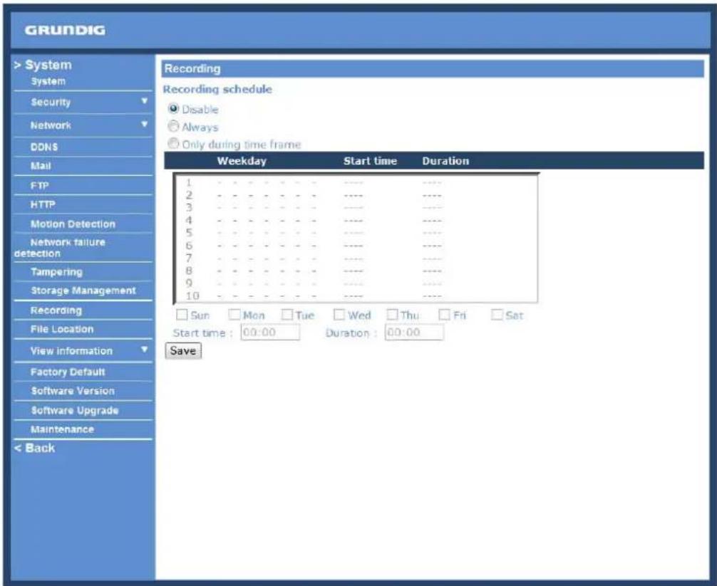
Activating Micro SD/SDHC Card Recording :
Two types of schedule mode are offered: "Always" and "Only during time frame". You can set up the time frame according to your requirements or you can choose "Always" to allow the Micro SD/SDHC Card Recording to be activated all the time.
Please click on the "Save" button to confirm the schedule mode.
Terminating Micro SD/SDHC Card Recording :
Select "Disable" to terminate the recording function.
9.13. File Location (on PC)
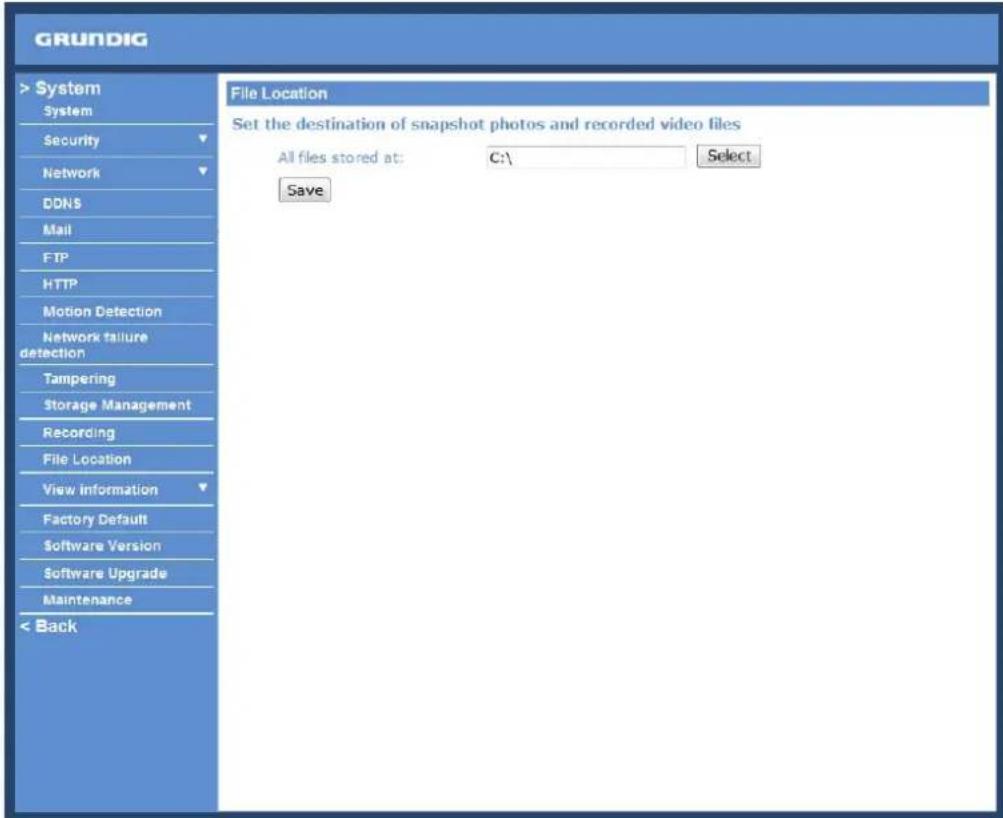
Users can specify a storage location for the snapshots and the live video recording. The default setting is: C:. Once the setting is confirmed, click on "Save," and all the snapshots and recordings will be saved in the designated location.
NOTE: Please make sure the selected file path contains valid characters such as letters and numbers.
NOTE: Users with the Windows 7 operating system on their PC need to follow the following procedure to be able to use the Snapshot function. First you need to log on to your computer as an Administrator. Then please go to Windows Start menu, click with the right mouse button on your Internet Browser and select in the appearing popup window "Run as Administrator". Afterwards you can log in to your camera as usual (as an administrator or user).
9.14. View Log File
Click on the link to view the system log file. The content of this file provides useful information about configuration and connections after system boot-up.
![[Tue May 8 08:49:00 2012] --Network interface initialized start [Tue May 8 08:49:08 2012] --Network interface initialized end [Tue May 8 08:49:08 2012] --Host IP = 192.168.44.36 [Tue May 8 08:49:08 2012] --Subnet Mask = 255.255.255.0 [Tue May 8 08:49:08 2012] --Gateway = 192.168.44.1 [Tue May 8 08:49:08 2012] --MAC address = B8:41:5F:01:C5:B0 [Tue May 8 08:49:38 2012] --admin@::ffff:192.168.44.73 GET / HTTP/1.1 [Tue May 8 08:49:39 2012] --admin@::ffff:192.168.44.73 GET /cgi-bin/setlogout.c [Tue May 8 08:49:39 2012] --admin@::ffff:192.168.44.73 GET /cgi-bin/ret.cgi HTT [Tue May 8 08:49:39 2012] --admin@::ffff:192.168.44.73 GET /cgi-bin/main.cgi HT [Tue May 8 08:49:39 2012] --admin@::ffff:192.168.44.73 GET /cgi-bin/top.cgi HTT [Tue May 8 08:49:40 2012] --admin@::ffff:192.168.44.73 GET /cgi-bin/center.cgi t [Tue May 8 08:49:42 2012] --admin@::ffff:192.168.44.73 GET /cgi-bin/showdate.c [Tue May 8 08:49:49 2012] --admin@::ffff:192.168.44.73 GET /cgi-bin/servermain [Tue May 8 09:15:37 2012] --admin@::ffff:192.168.44.73 GET /cgi-bin/storage.cgi](/content/2026/05/1039223/images/d0cf5820a9fffe5d5d4e8bf84a6b3a7b2ea7cc682fcfac6f22fcefc7280f5dd0.jpg)
9.15. View User Information
The Administrator can view each user's login information and their privileges (see section 9.2. Security).
View User Login Information :
All the users in the network will be listed in the "User Information" zone, as shown below. The picture below shows: User: 4321
This indicates that one user's login username is: User, and the password is: 4321
![[Tue May 8 08:49:00 2012] --Network interface initialized start [Tue May 8 08:49:08 2012] --Network interface initialized end [Tue May 8 08:49:08 2012] --Host IP = 192.168.44.36 [Tue May 8 08:49:08 2012] --Subnet Mask = 255.255.255.0 [Tue May 8 08:49:08 2012] --Gateway = 192.168.44.1 [Tue May 8 08:49:08 2012] --MAC address = B8:41:5F:01:C5:B0 [Tue May 8 08:49:38 2012] --admin@::ffff:192.168.44.73 GET / HTTP/1.1 [Tue May 8 08:49:39 2012] --admin@::ffff:192.168.44.73 GET /cgi-bin/setlogout.c [Tue May 8 08:49:39 2012] --admin@::ffff:192.168.44.73 GET /cgi-bin/ret.cgi HTT [Tue May 8 08:49:39 2012] --admin@::ffff:192.168.44.73 GET /cgi-bin/main.cgi HT [Tue May 8 08:49:39 2012] --admin@::ffff:192.168.44.73 GET /cgi-bin/top.cgi HTT [Tue May 8 08:49:40 2012] --admin@::ffff:192.168.44.73 GET /cgi-bin/center.cgi H [Tue May 8 08:49:42 2012] --admin@::ffff:192.168.44.73 GET /cgi-bin/showdate.c [Tue May 8 08:49:49 2012] --admin@::ffff:192.168.44.73 GET /cgi-bin/servermain [Tue May 8 09:15:37 2012] --admin@::ffff:192.168.44.73 GET /cgi-bin/storage.cgi](/content/2026/05/1039223/images/bec1d3e3ad442f47cb164dc4b07a83fe3d853dd959ee65481f13de4471536f58.jpg)
View User Privilege :
If you click on "Get user privacy" at the bottom of the page, the Administrator will be able to view each user's privileges.
![GRUNDIG > System System Security Network DDNS Mail FTP HTTP Motion Detection Network failure detection Tampering Storage Management Recording File Location View information Log file User information Parameters Factory Default Software Version Software Upgrade Maintenance < Back Parameter List Mega Pixel Camera Initial Configuration File [Camera setting] =- exposure mode = min shutter speed = <8> fixed shutter speed = <56> white balance mode = white balance regain = <57> white balance bgain = <54> brightness value = <128> sharpness value = <4> contrast value = <64> saturation = <64>](/content/2026/05/1039223/images/11e98ceb2b866eb342cc8e6bf1ae2fa7d449145da01bd228e260ce25a5643e0d.jpg)
As the picture above shows: User: 1:1:0:1
1:1:0:1 = I/O access : Camera control : Talk : Listen (see 9.2. Security)
This denotes that the user has been granted the privileges of I/O access, Camera control and Listen.
9.16. View Parameters
Click on this item to view the entire system's parameter setting.
![GRUNDIG > System System Security Network DDNS Mail FTP HTTP Motion Detection Network failure detection Tampering Storage Management Recording File Location View information Log file User information Parameters Factory Default Software Version Software Upgrade Maintenance < Back Parameter List Mega Pixel Camera Initial Configuration File [Camera setting] exposure mode = min shutter speed = <8> fixed shutter speed = <56> white balance mode = white balance regain = <57> white balance bgain = <54> brightness value = <128> sharpness value = <4> contrast value = <64> saturation = <64>](/content/2026/05/1039223/images/f76e823e5a23b0c5b842b1ba0633bba9cde9bbd27fcf40ac7965e8e5814c977c.jpg)
9.17. Factory Default
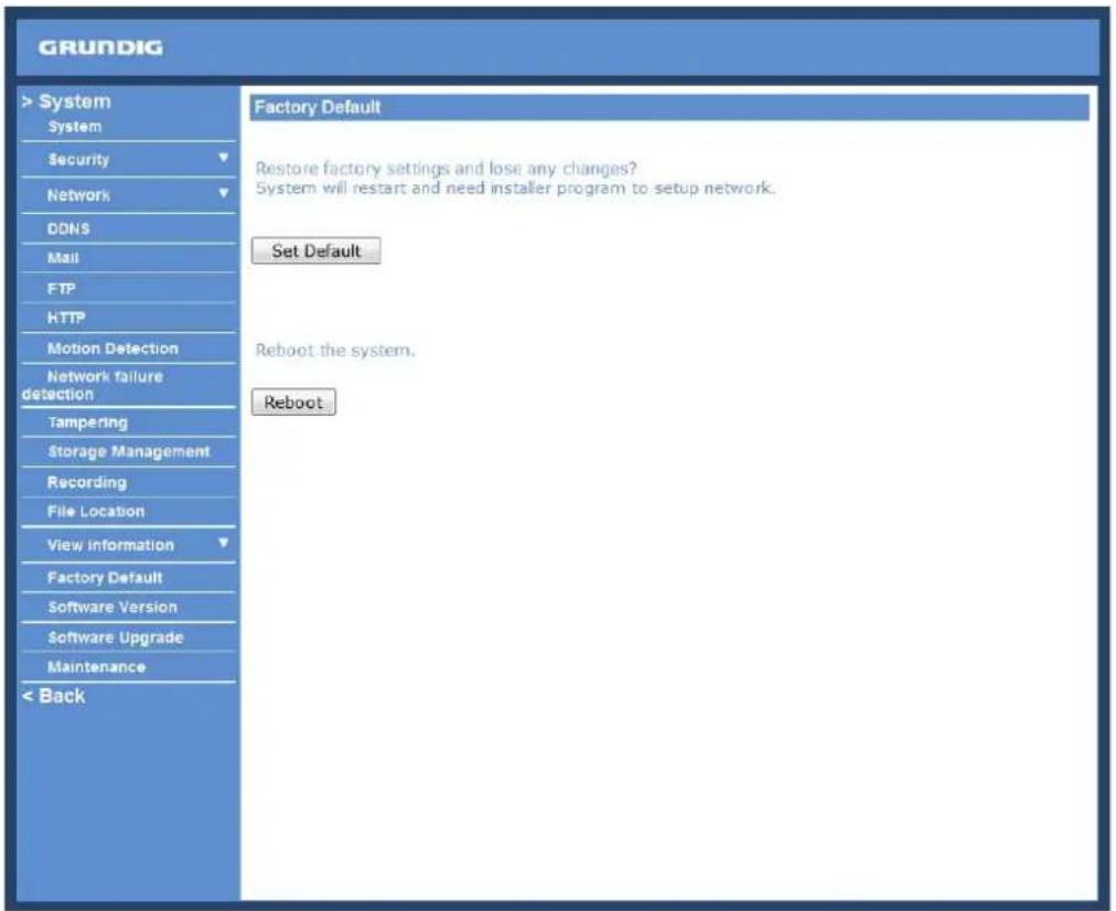
The factory default setting page is shown below. Follow the instructions to reset the IP Camera to factory default setting if needed.
Set Default :
Click on the "Set Default" button to recall the factory default settings. After 30 seconds the system will restart.
NOTE: The IP address will also be restored to default (192.168.1.1).
Reboot :
When you click on the "Reboot" button, the system will restart without changing the current settings.
9.18. Software Version
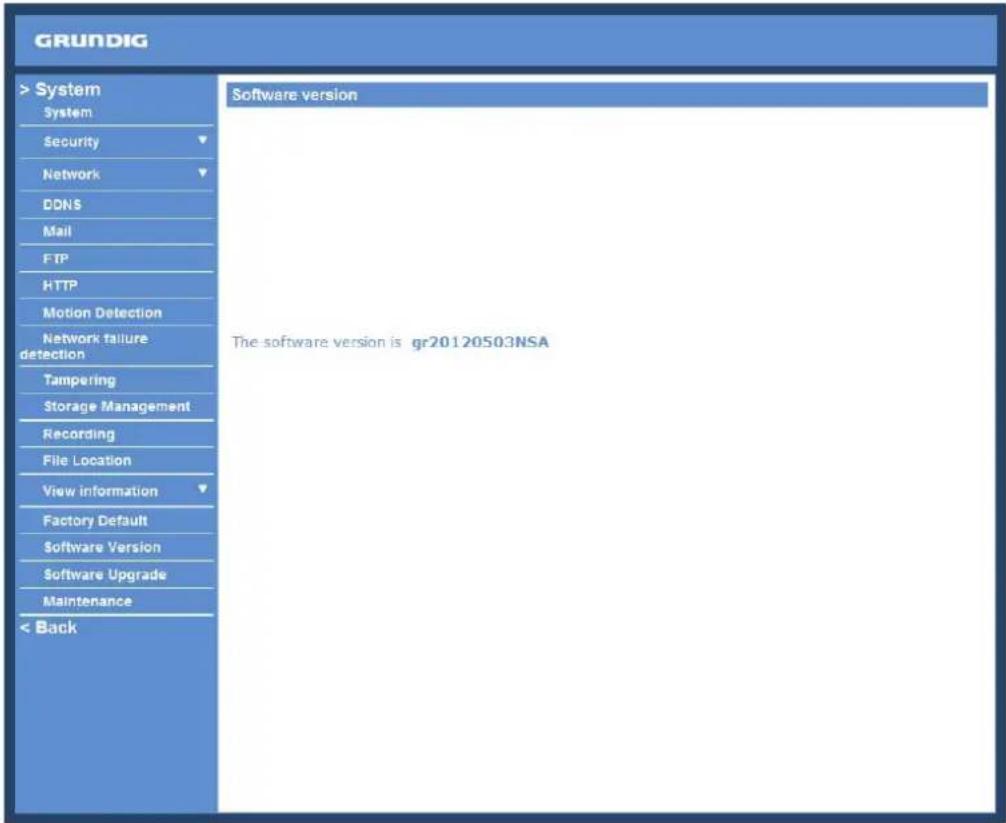
The current software version is displayed in the software version page, which is shown in the picture below.
9.19. Software Upgrade
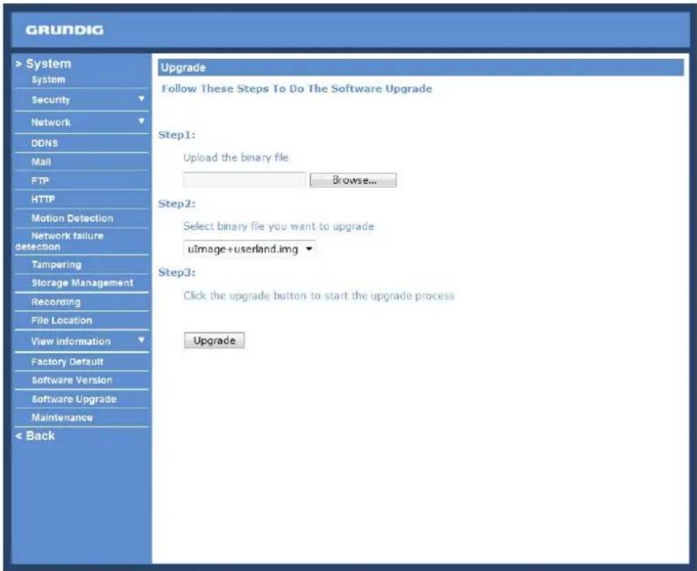
Software upgrade can be carried out on the "Software Upgrade" page, as shown below.
NOTE: Make sure the upgrade software file is available before carrying out the software upgrade.
The procedure of a software upgrade is as follows:
Step 1: Click on "Browse" and select the following binary file to be uploaded: ulmage+userland.
NOTE: Do not change the upgrade file name, or the system will fail to find the file.
Step 2: Pull down the upgrade binary file list and select the file you want to upgrade; in this case, select "ulmage+userland".
Step 3: Click on "Upgrade". The system will first check whether the upgrade file exists or not, and then begin to upload the upgrade file. Subsequently, the upgrade status bar will be displayed on the page. When 100% is reached, the upgrade process is finished.
After the upgrade process is finished, the Viewer will return to the Home page.
Step 4: Close the video browser.
Step 5: Go to "Start" on your Windows desktop, activate "Control Panel", and then double-click on "Add or Remove Programs". In the "Currently installed programs" list, select "GRUNDIG Viewer" and click on the button "Remove" to uninstall the existing GRUNDIG Viewer.
Step 6: Open a new web browser, re-login the IP Camera, and then allow the automatic download of the GRUNDIG Viewer.
9.20. Maintenance
Users can export configuration files to a specified location and retrieve data by uploading an existing configuration file to the IP Camera. This is especially convenient if you want to have the same configuration for multiple cameras.
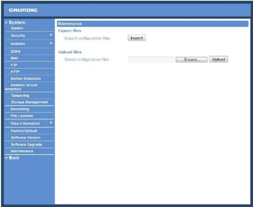
Export:
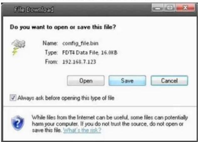
Users can save the system settings by exporting the configuration file (.bin) to a specified location for future use. When you click on the "Export" button, the File Download window will pop up as shown below.
Click "Save" and specify a desired location for saving the configuration file.
Upload:
To copy an existing configuration file to the IP Camera, please first click on "Browse" to select the configuration file, and then click on the "Upload" button for uploading.
NOTE: The cameras need to have the same software version to upload the configuration file.
10. Streaming Settings
10.1. Video Format
Video Resolution :
Under the Video Resolution section, the available video resolution formats include MJPEG and H.264. Please refer to Chapter 6. Video Resolution Setup for more combination details.
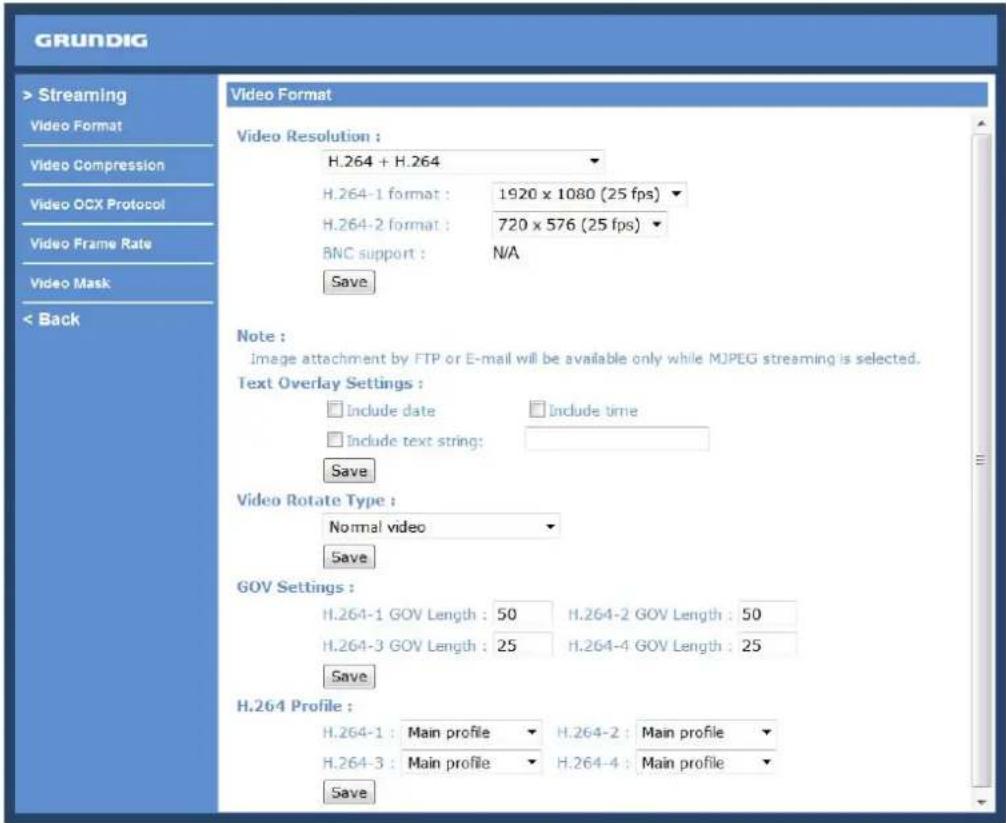
Click on "Save" to confirm the setting.
Text Overlay Settings :
Users can select these items to display data (date/time/text) on the live video pane. The maximum length of the string is 18 alphanumeric characters.
Click "Save" to confirm the Text Overlay setting.
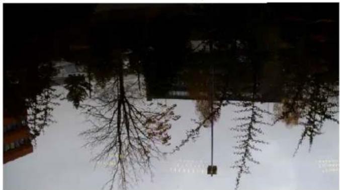
Users can change the video display type if necessary. The selectable video rotation types include Normal video, Flip video, Mirror video, 90 degree counter-/clockwise and 180 degree rotation. Differences between these types are illustrated below.
Suppose the displayed image of IP Camera is shown as the figure below.
natural_image
Silhouetted trees reflected in a snowy landscape with buildings in the background (no visible text or symbols)To rotate the image, users can select "Flip video", for instance. Then the displayed image will be reversed as shown below.
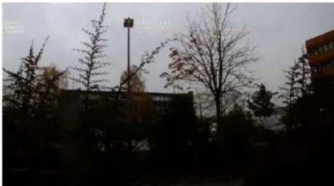
natural_image
Silhouetted trees and a street lamp in an urban setting with buildings in the background (no visible text or symbols)The following are descriptions of different video rotation types.
- Flip video:
If you select
- Mirror video:
If you select
- 90 degree counter-/clockwise:
Selecting <90 degree counter-/clockwise> will inverse the image 90° counter-/clockwise. The image will only be shown with the right proportions in "Fullscreen View". Click on the Fullscreen Button (third button from the left) on the main page to enlarge the image and double-click to go back to "Normal View".
- 180 degree rotation:
Selecting the <180 Degree rotation> will inverse the image 180° counter-/clockwise.
Click "Save" to confirm the setting.
GOV Settings :
Users can set the GOV length to determine the frame structure (I-frames and P-frames) in a video stream for saving bandwidth. Longer GOV means decreasing the frequency of I-frames. The setting range for the GOV length is from 2 to 64. The default setting of GOV is 30.
Click "Save" to confirm the GOV setting.
This camera provides three H.264 streaming formats to meet the requirements from viewing devices, the surveillance system, and the network condition of the application and installation environment.
H.264 Baseline profile: Standard Efficiency Encoding Format
H.264 Main profile: Good Efficiency Encoding Format
H.264 High profile: High Efficiency Encoding Format
10.2. Video Compression
Users can specify the values for MJPEG/H.264 compression mode in the video compression page (see the picture below), depending on the application.
MJPEG compression setting (MJPEG Q (Quality) factor):
A higher value implies higher bit rates and a higher visual quality. The default setting is 35; the setting range is from 1 to 70.
Click "Save" to confirm the setting.
H.264-1 / H.264-2 / H.264-3 / H.264-4 bit rate:
The default setting of H.264-1 is 4096 kbps and of H.264-2/H.264-3/H.264-4 is 1024 kbps. The setting range for H.264-1 is from 64 to 8192 kbps and for H.264-2/H.264-3/H.264-4 it is from 64 to 2048 kbps.
Click "Save" to confirm the setting.
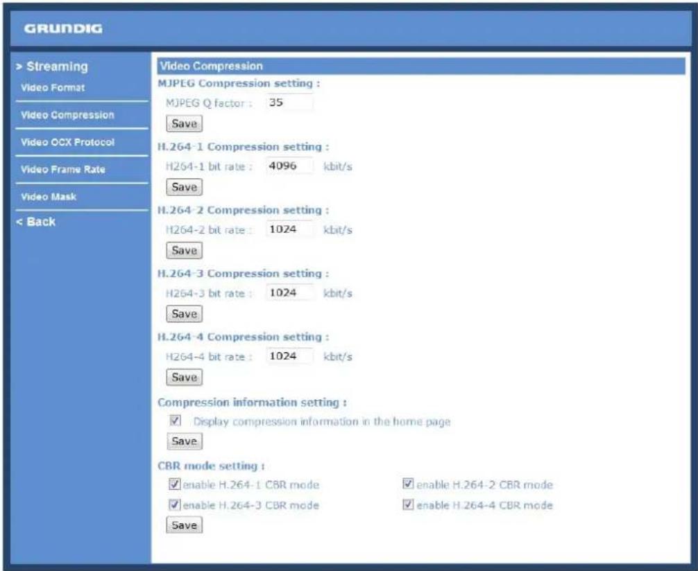
Compression information setting :
Users can also decide whether to display compression information on the Home page.
Click "Save" to confirm the setting.
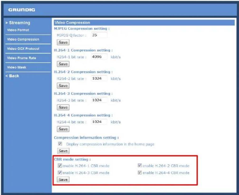
CBR mode setting :
The CBR (Constant Bit Rate) mode can become the preferred bit rate mode if the available bandwidth is limited. It is important to take into account the image quality when you choose to use CBR mode.
Click on "Save" to confirm the setting.
10.3. Video OCX Protocol
In the Video OCX protocol setting page, users can select RTP over UDP, RTP over TCP, RTSP over HTTP or MJPEG over HTTP, for streaming media over the network. In the case of multicast networking, users can select the Multicast mode. The Video OCX Protocol page is as follows:
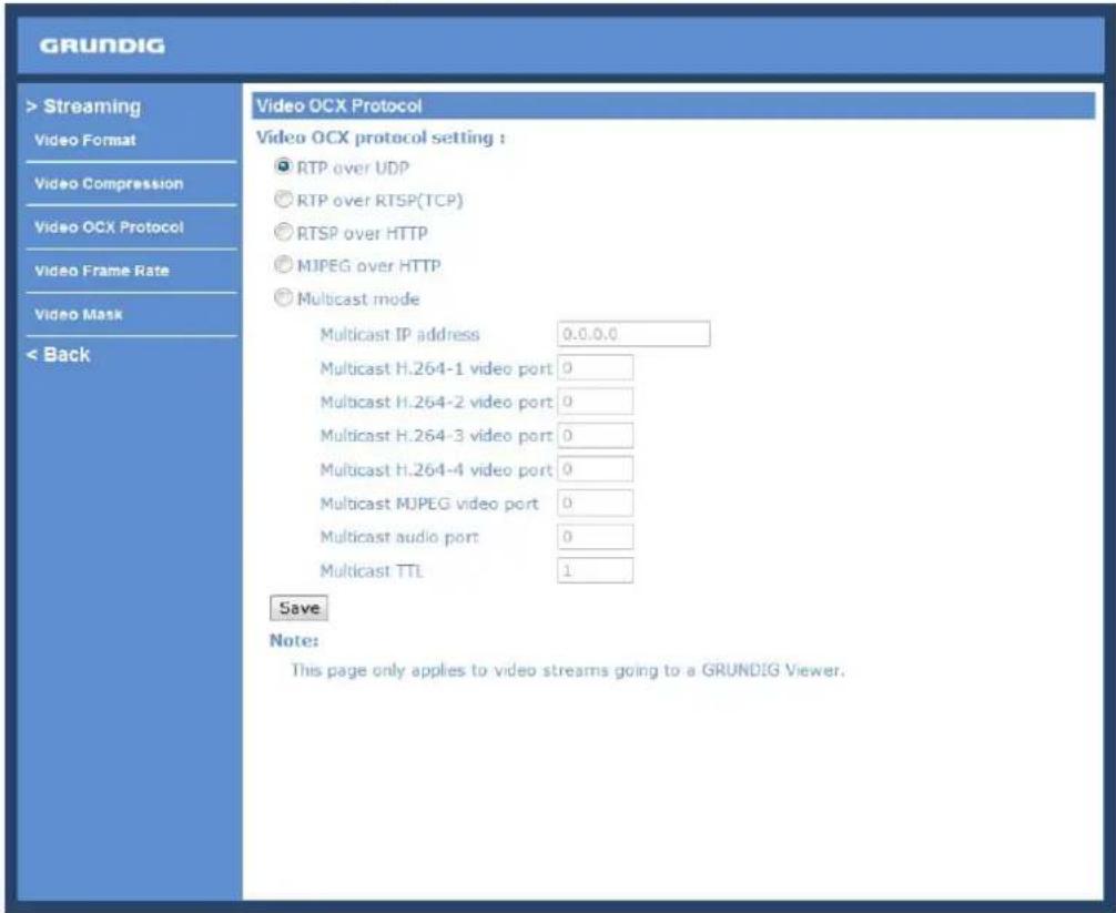
Video OCX protocol setting options include:
- RTP over UDP / RTP over RTSP (TCP) / RTSP over HTTP / MJPEG over HTTP (Select a mode according to your data delivery requirements.)
- Multicast Mode: Enter all required data, including multicast IP address, H.264 video port, MJPEG video port, audio port and TTL into each blank.
Click on "Save" to confirm the setting.
10.4. Video Frame Rate
Video frame skipping is for saving bandwidth if necessary. The setting page is shown below.
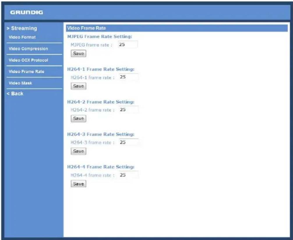
MJPEG / H.264-1 / H.264-2 / H.264-3 / H.264-4 Frame Rate:
The default setting of MJPEG/H.264-1/H.264-2/H.264-3/H.264-4 Frame Rate is 25 fps. The setting range is from 1 to 25.
Click on
NOTE: A lower frame rate will decrease video smoothness.
10.5. Video Mask
There are five video masks which can be set by the users.
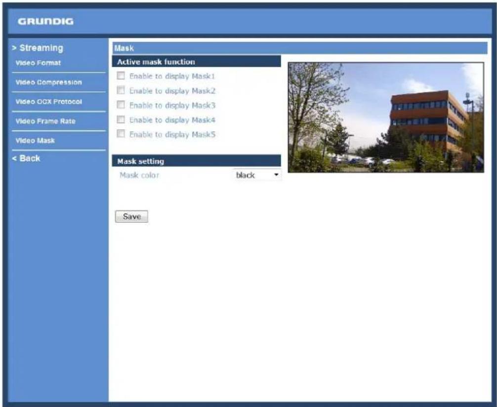
Active Mask Function :
- Add a Mask:
When you check a Video Mask checkbox, a red frame will come out in the Live Video pane at the right side. Use the mouse to adjust the mask's size and drag and drop the frame to place it on the target zone.
NOTE: It is suggested to set the Video Mask twice as big as the object.
- Cancel a mask:
If you uncheck the checkbox of the Video Mask that is meant to be deleted, the selected mask will disappear from the Live Video pane instantly.
Mask Setting :
- Mask colour:
The selection of Mask colours includes red, black, white, yellow, green, blue, cyan, and magenta.
Click on "Save" to confirm the setting.
11. Camera Settings
The picture below is the camera configuration page. Details of each parameter setting are described in the following subsections.
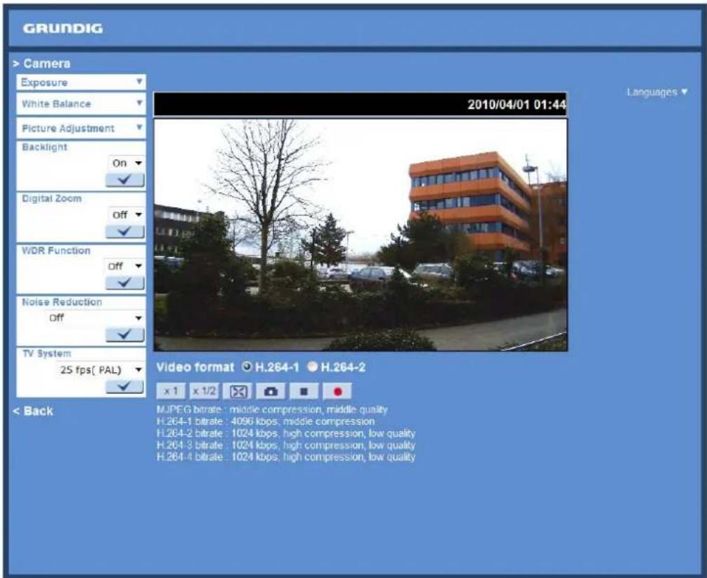
11.1. Exposure Setting
Display of the Exposure pull-down menu:
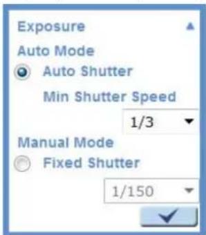
The exposure is the amount of light received by the image sensor and is determined by the width of lens diaphragm opening, the amount of exposure by the sensor (shutter speed) and other exposure parameters. With this item, users can define how the Auto Exposure function works.
Auto Mode :
- Auto Shutter Mode:
This function is used to control the shutter speed and to adjust the iris automatically according to the light intensity. It is also effective if a fixed iris lens is being used. The minimum shutter speed range is configurable from 1/1.5 to 1/425 sec.
Manual Mode:
- Fixed Shutter Mode:
In this mode, a fixed shutter speed can be selected from the drop-down menu. The shutter speed range is from 1/10000 to 1/1.5 sec. With 18 options depending on the camera model. Users can choose a suitable shutter speed according to the environmental illumination.
Click on <√> to confirm the new setting.
11.2. White Balance Setting
Display of the White Balance pull-down menu:
![White Balance Auto ATW Manual Rgain: 57 [0..127] Bgain: 54 [0..127]](/content/2026/05/1039223/images/dc41215a168de7a2500116c2557bef7841db17517908f75ef83ba82cb39c32a1.jpg)
To display natural colours, the camera needs to know the reference colour temperature of the light source. Based on this reference colour temperature the camera will calculate the correct values for all colours. The camera can perform a measurement by itself or the user can set up the reference colour temperature manually. The scale unit of the colour temperature is Kelvin [K]. The following list shows the colour temperature of some light sources for reference.
Users can select one of the White Balance Control modes according to the operating environment.
Light Sources :
Cloudy Sky (Colour Temperature: 6,000 to 8,000 K)
Noon Sun and Clear Sky (Colour Temperature: 6,500 K)
Household Lighting (Colour Temperature: 2,500 to 3,000 K)
75-watt Bulb (Colour Temperature: 2,820 K)
Candle Flame (Colour Temperature: 1,200 to 1,500 K)
Auto Mode :
The Auto Balance White mode is suitable for an environment with a light source having a colour temperature range from 2700 \~ 7600K.
ATW Mode (Auto Tracking White Balance):
With the Auto Tracking White Balance function, the white balance in a scene will be automatically adjusted while temperature colour is changing. The ATW Mode is suitable for environments with a light source having a colour temperature in the range roughly from 2450 \~ 10500K.
Manual Mode :
In this mode, users can change the White Balance value manually. Users can select a number between 0 \~ 127 in the "R-Gain/B-Gain" item to gain the red/blue illuminant on the Live Video Pane.
Click on <√> to confirm the new setting.
11.3. Picture Adjustment
Display of the Picture Adjustment pull-down menu:
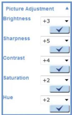
Brightness:
The users can adjust the image's brightness by adjusting the item. Please select a number from the range of -12 to +13. To increase the video brightness, select a bigger number.
Click on <√> to confirm the new setting.
Sharpness:
Increasing the sharpness level can make the image look sharper. Please select a number from the range of +0 to +15. This function especially enhances the object's edges.
Click on <√> to confirm the new setting.
Contrast:
The camera image contrast level is adjustable. Please choose from a range of -6 to +19.
Click on <√> to confirm the new setting.
Saturation:
The camera image saturation level is adjustable. Please select from a range of -6 to +19.
Click on <√> to confirm the new setting.
Hue:
The camera image hue level is adjustable. Please select from a range of -12 to +13.
Click on <√> to confirm the new setting.
11.4. Backlight Setting
Based on various lighting situations, users can turn the function of Backlight Compensation on or off to optimise the video quality. The default value of Backlight is: Off.
Click on <√> to confirm the new setting.
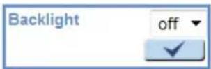
11.5. Digital Zoom Setting
The camera's Digital Zoom is adjustable from x2 to x8.
Click on <√> to confirm the new setting.
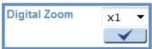
11.6. WDR Function
The Wide Dynamic Range (WDR) function is for solving high contrast or changing light issues to improve the video display. The WDR is adjustable from Low, Mid to Hi. A higher level of WDR represents a wider dynamic range, so that the IP Camera can catch a greater scale of brightness.
Click on <√> to confirm the new setting.
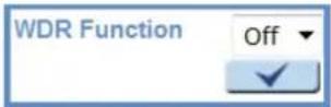
11.7. Noise Reduction
The IP Camera provides multiple
The different level options for 3D Noise Reduction (3DNR) include Low, Mid and Hi. A higher level of 3DNR generates relatively enhanced noise reduction.
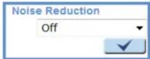
The proprietary Smart Picture Quality (SPQ) video processing method can drastically minimise motion blur and reduce the noise especially in a low-light environment. The combination of SPQ and 3DNR at different levels further yields exceptional video performance in various conditions.
The Noise Reduction function is configurable with the following options:
- 3DNR Low
- 3DNR Mid
- 3DNR Hi
- SPQ
- SPQ + 3DNR Low
- SPQ + 3DNR Mid
- SPQ + 3DNR Hi
Click on <√> to confirm the new setting.
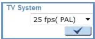
11.8. TV System Setup
Select the video format that matches the present TV system.
Click on <√> to confirm the new setting.
12. Logout
When you press the "Logout" tab at the top of the page, the login window will pop up. This permits login with another user name.

13. CMS Software Introduction
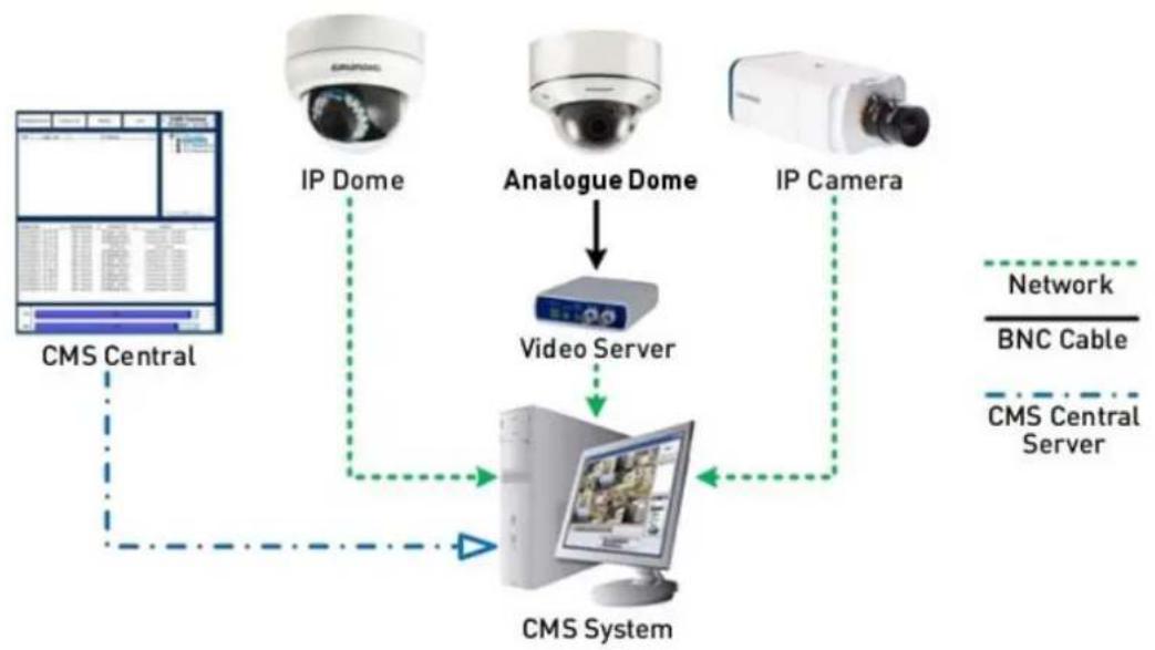
The Central Management System (CMS) software bundles IP cameras and analogue cameras that are connected to the network via the Video Server into one system. Offering powerful functionalities via intuitive interface, it is a centralised monitoring solution for your video surveillance equipments.
The GRUNDIG CMS Software gives the user access to monitor multiple IP Cameras and Video Servers, and allows the user to monitor simultaneously 16 sites per group (up to 10 groups) within several clicks.
For further information on the CMS software, please refer to the supplied CD.
flowchart
graph TD
    A["CMS Central"] --> B["IP Dome"]
    B --> C["Analogue Dome"]
    C --> D["Video Server"]
    D --> E["CMS System"]
    E --> F["IP Camera"]
    F --> G["Network"]
    G --> H["BNC Cable"]
    E --> I["CMS Central Server"]
14. Internet Security Settings
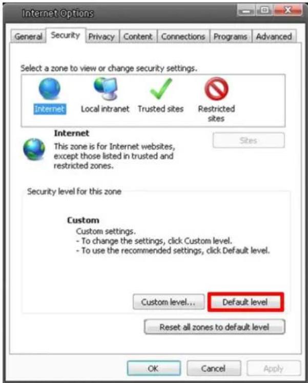
If the ActiveX control installation is blocked, please either set the Internet security level to default or change ActiveX controls and plug-in settings.
Internet Security Level : Default
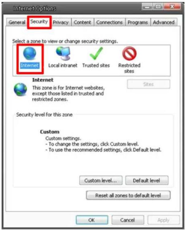
Step 1: Start the Internet Explorer.
Step 2: Select
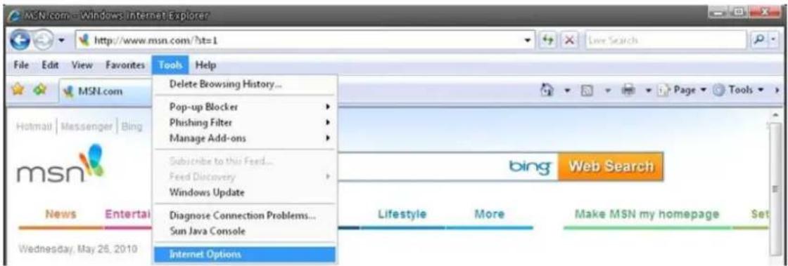
Step 3: Click on the
Step 4: Down the page, click on "Default level..." and then click "OK" to confirm the setting. Close the browser window, and open a new one later when accessing the IP Camera.
ActiveX Controls and Plug-in Settings :
Step 1\~3: Please refer to the previous section above.
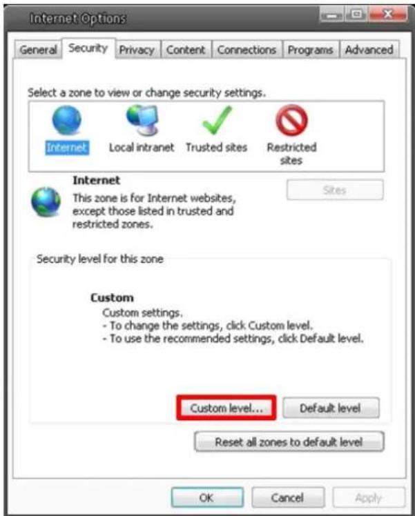
Step 4: Down the page, click on "Custom level..." (see the picture below) to change ActiveX controls and plug-in settings.
The Security Settings screen is displayed as shown below:
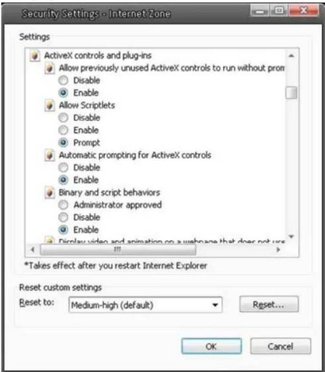
Step 5: Under "ActiveX controls and plug-ins", set ALL items (as listed below) to
ActiveX controls and plug-in settings:
- Allow previously unused ActiveX controls to run without prompt
- Allow Scriptlets
- Automatic prompting for ActiveX controls
- Binary and script behaviors
- Display video and animation on a webpage that does not use external media player
- Download signed ActiveX controls
- Download unsigned ActiveX controls
- Initialize and script ActiveX controls not marked as safe for scripting
- Run ActiveX controls and plug-ins
- Script ActiveX controls marked as safe for scripting
Step 6: Click on
Step 7: Click on
Step 8: Close the browser window, and open a new one later for accessing the IP Camera.
15. GRUNDIG Viewer Download Procedure
The procedure of the GRUNDIG Viewer software download is specified as follows:
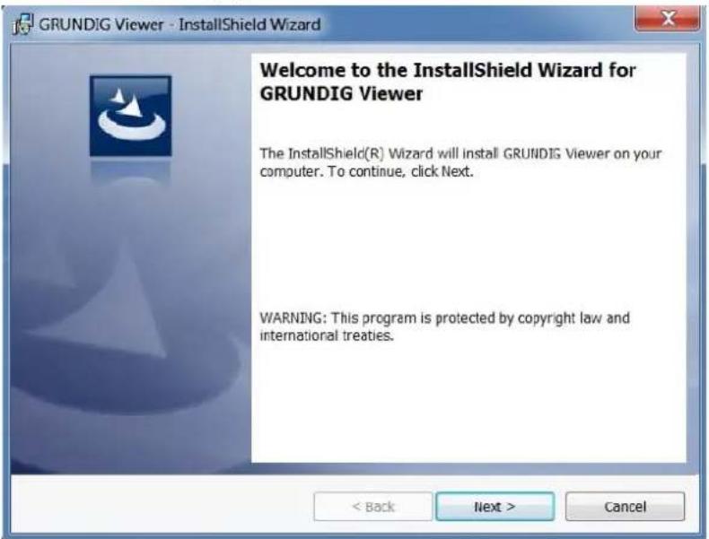
Step 1: In the GRUNDIG Viewer installation page, click "Next" to start the installation.
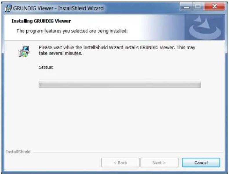
Step 2: Setup starts. Please wait for a while until the loading bar runs out.
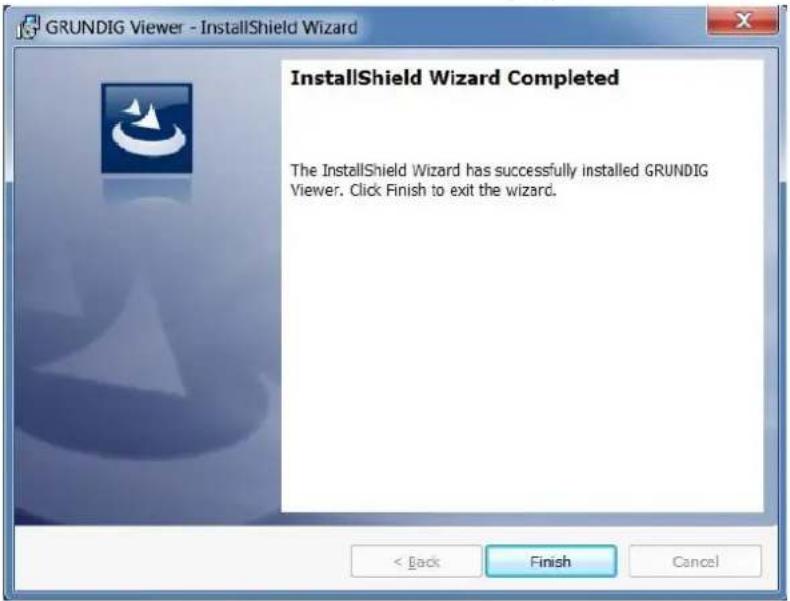
Step 3: Click on "Finish" to close the GRUNDIG Viewer installation page.
Then, the IP Camera's Home page will be displayed as follows:
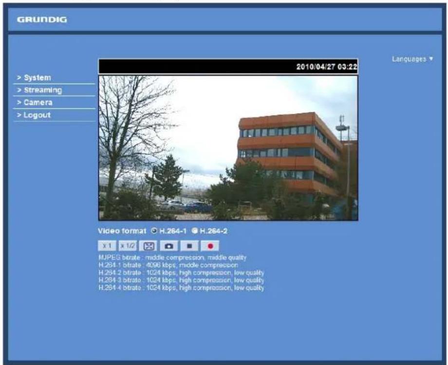
NOTE: Please note that the function buttons may vary depending on the camera model.
16. Install UPnP Components
Please follow the instructions below to install UPnP components. (The procedure is for Windows XP, for other systems please refer to the corresponding manuals.)
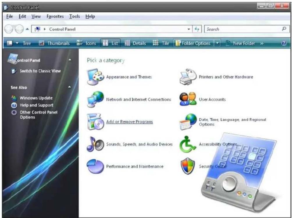
Step 1: Go to "Start", click on "Control Panel", and then double-click on "Add or Remove Programs".
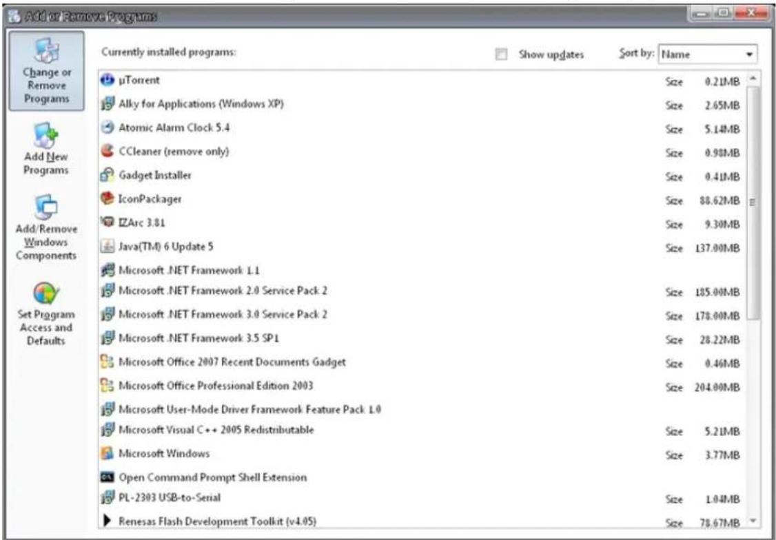
Step 2: Click on "Add/Remove Windows Components" in the Add or Remove Programs page.
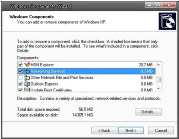
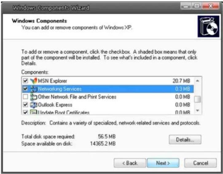
Step 3: Select "Networking Services" from the Components list in the Windows Components Wizard window, and then click on "Details".
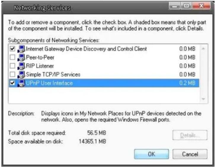
Step 4: Select "UPnP User Interface" in the Networking Services' subcomponents list and then click on "OK".
Step 5: Click on "Next" in the Windows Components Wizard page.
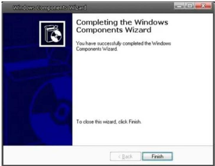
Step 6: Click on "Finish" to complete the installation.
17. Deleting the Existing GRUNDIG Viewer
Users who have installed the GRUNDIG Viewer for 1.3 Megapixel Series IP Cameras on the PC need to delete the existing GRUNDIG Viewer first from the PC before accessing this IP Camera.
Deleting the GRUNDIG Viewer :
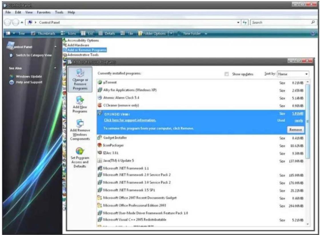
Click on "Control Panel", and then click on "Add or Remove Programs". In the "Currently installed programs" list, select "GRUNDIG Viewer" and click the button "Remove" to uninstall the existing GRUNDIG Viewer as shown in the figure below.
Deleting Temporary Internet Files :
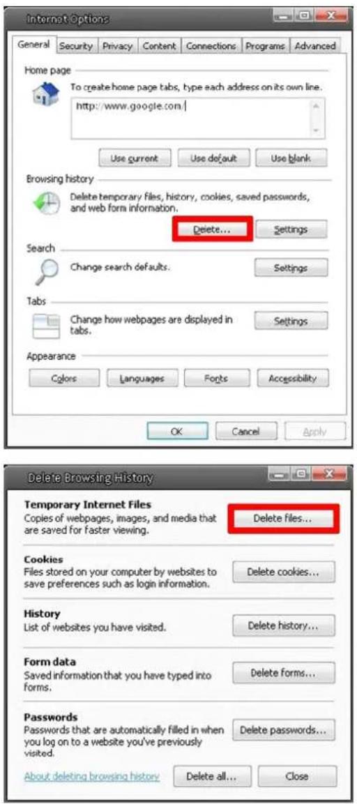
To improve the browser performance, it is suggested to clean up all the files in the Temporary Internet Files. The procedure is as follows (for other web browsers please read the corresponding manuals):
STEP 1: Click on the "Tools" tab and select the option "Internet Options".
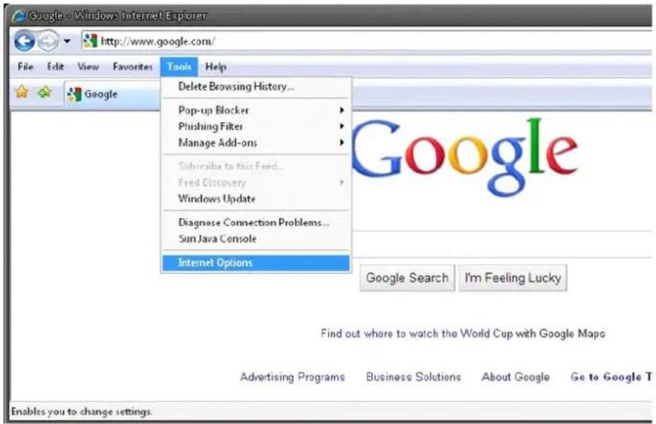
STEP 2: Click on "Delete" in the first pop-up window. Then tap "Delete Files" in the "Temporary Internet files" section in the next pop-up window.
Specifications GCI-K1812W
| Image Sensor 1/2.7" CMOS Omnivision, 2 MegapixelPixels - Total 1920(H) x 1080(V)Sensitivity Colour 0.6 Lux@F1.5(IRE50), 0.1 Lux@F1.5(IRE30) | |
| Lens Focal Length 4 mm | |
| Viewing Angle 78° | |
| Motion Detection On/ Off/ Sensitivity/ Area setting | |
| Privacy zones 5 zones, rectangle | |
| White Balance ATW, AWB, Manual | |
| Shutter Speed 1 sec to 1/10,000 sec | |
| Web Browser MS Internet Explorer 6.0 (or higher), Firefox, Google Chrome, Safari | |
| Number of Clients Up to 20 user | |
| Video Compression H.264, MJPEG | |
| Video Resolution Full HD 1080p/ SXGA/ HD 720p/ XGA/SVGA/ 4CIF/ VGA/ CIF | |
| Video Streaming H.264 Only, MJPEG Only, H.264+H.264, H.264+MJPEG,H.264+H.264+H.264, H.264+H.264+MJPEG, H.264+H.264+H.264, H.264+H.264+H.264+H.264, H.264+H.264+H.264+MJPEG | |
| Network Protocol | IPv4/v6, TCP/IP, UDP, RTP, RTSP, HTTP, HTTPS, DHCP, PPPoE, UPnP, SMTP, ICMP, IGMP, SNMP, IEEE802.1x, QoS, ONVIF |
| SD memory | Micro SD/SDHC |
| Alarm Event | Motion Detection or Schedule: Image transfer or alarm message by FTP, Image transfer or alarm message by E-mail, recording on SD-card and send HTTP notification |
| Input/Output sockets | RJ-45, Micro SD Card Slot |
| Firmware Upgrade | Firmware upgrade by Web Browser |
| Configuration Upload & Download configuration on remote PC | |
| Protection Rating IP66 | |
| Operating Temperature | -25°C ~ +55°C |
| Regulation | CE, FCC, RoHS Compliant |
| Supply Voltage | PoE IEEE 802.3af |
| Languages | English, German, French, Italian, Russian |
| BLC | On/Off |
| WDR | High/Medium/Low |
| Digital Noise Reduction (DNR) | 3DNR,SMR |
| Tampering Alarm | On/Off |
| Digital Zoom | Off ~ 8x |
| Power Consumption | 3.5 W |
| Weight | 0.18 kg |
| Dimensions (wxhxd) | ∅ 117 x 50 mm |
Dimensions
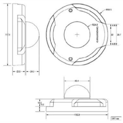
EC Declaration of Conformity
CE
GCI-K1812W 2 Megapixel Full HD Flat Fixed Dome IP-Camera 4mm Soft D/N
It is hereby certified that the products meet the standards in the following relevant provisions:
EC EMC Directive 2004/108/EC Low Voltage Directive 2006/95/EC
Applied harmonised standards and technical specifications:
Measurement Procedure EMI: AS/NZS CISPR 22: 2006, EN55022 CLASS A: 2006 + A1: 2007 EN61000-3-2: 2006 + A2: 2009, EN61000-3-3: 2008
Measurement Procedure EMS: AS/NZS CISPR 22: 2006, EN 50130-4: 1995 + A1: 1998 + A2: 2003, IEC/EN 61000-4-2: 2008, IEC/EN 61000-4-3: 2008, IEC/EN 61000-4-4: 2004, IEC/EN 61000-4-5: 2006 IEC/EN 61000-4-6: 2009, IEC/EN 61000-4-8: 2009, IEC/EN 61000-4-11: 2004
ASP AG
Lüttringhauser Str. 9 42897 Remscheid Germany
- Content:
- Streaming Settings
- Camera Settings
- Logout
- Introduction
- Important Safety Instructions
- Package Contents
- Installation
- Camera Overview
- System Requirements
- Ethernet Connection
- Installation and Connection
- Accessing the Camera
- Video Resolution Setup
- Browser-based Viewer Introduction
- System setting :
- Streaming setting :
- Camera setting :
- Logout :
- Languages :
- Home Page
- System Related Settings
- Host Name & System Time Setting
- Host Name :
- Time Zone :
- Enable Daylight Saving Time :
- Sync with Computer Time :
- Manual :
- Sync with NTP server :
- Security
- Admin Password :
- Add User :
- - I/O access:
- - Camera control:
- - Talk/Listen:
- Manage User :
- CA Certificate :
- Network
- 9.4.DDNS
- 9.6.FTP
- HTTP
- Motion Detection
- Network Failure Detection
- Tampering
- Tampering Alarm :
- Tampering Duration :
- Triggered Action (Multi-option):
- Storage Management (on Camera)
- Recording (on Camera)
- File Location (on PC)
- View Log File
- View User Information
- View Parameters
- Factory Default
- Software Version
- Software Upgrade
- Maintenance
- Video Format
- Video Compression
- Video OCX Protocol
- Video Frame Rate
- Video Mask
- Exposure Setting
- Manual Mode:
- - Fixed Shutter Mode:
- White Balance Setting
- Light Sources :
- Auto Mode :
- ATW Mode (Auto Tracking White Balance):
- Manual Mode :
- Picture Adjustment
- Brightness:
- Sharpness:
- Contrast:
- Saturation:
- Backlight Setting
- Digital Zoom Setting
- WDR Function
- Noise Reduction
- TV System Setup
- CMS Software Introduction
- Internet Security Settings
- GRUNDIG Viewer Download Procedure
- Install UPnP Components
- Deleting the Existing GRUNDIG Viewer
- Dimensions
- EC Declaration of Conformity
- CE
- ASP AG
Brand : GRUNDIG
Model : GCI-K1812W
Category : Security Camera