LMD-M12 - Air conditioner Maxicool - Free user manual and instructions
Find the device manual for free LMD-M12 Maxicool in PDF.


| Product Type | Portable Air Conditioner |
| Brand | Maxicool |
| Model | LMD-M12 |
| Dimensions (W x D x H) | 450 x 350 x 700 mm |
| Weight | 28 kg |
| Power Supply | 220-240V ~ 50Hz |
| Cooling Capacity | 12000 BTU/h |
| Functions | Cooling, Fan, Dehumidification, Sleep Mode, Timer |
| Energy Efficiency Ratio (EER) | 2.5 |
| Refrigerant Type | R410A |
| Noise Level | 52 dB(A) |
| Airflow Volume | 350 m³/h |
| Filter Cleaning | Every 2 weeks (mesh filter) |
| Safety Features | Overheat protection, auto shut-off |
| Remote Control | Yes (included) |
| Exhaust Hose Length | 150 cm |
| Drainage Method | Self-evaporative or manual drain |
| Warranty | 1 year |
Frequently Asked Questions - LMD-M12 Maxicool
User questions about LMD-M12 Maxicool
0 question about this device. Answer the ones you know or ask your own.
Ask a new question about this device
Download the instructions for your Air conditioner in PDF format for free! Find your manual LMD-M12 - Maxicool and take your electronic device back in hand. On this page are published all the documents necessary for the use of your device. LMD-M12 by Maxicool.
USER MANUAL LMD-M12 Maxicool
Before using your air conditioner, please read this manual carefully and keep it for future reference.
INVERTER ONE-TWO/ ONE-THREE/ ONE-FOUR/ ONE-FIVE SPLIT-TYPE
ROOM AIR CONDITIONER
USER'S MANUAL
MODEL: MMD2-18HDI
MMD3-24HDI
LMD-M07
LMD-M09
LMD-M12
LMD-M18
CMD-M09
CMD-M12
WMD-M09
WMD-M12
DMD-M09
DMD-M12
Read This Manual
Inside you will find many helpful hints on how to use and maintain your air conditioner properly. Just a little preventative care on your part can save you a great deal of time and money over the life of your air conditioner. You'll find many answers to common problems in the chart of troubleshooting tips. If you review the chart of Troubleshooting Tips first, you may not need to call for service.
CONTENTS
SOCIABLE REMARK
Sociable remark....2
SAFETY PRECAUTIONS
Warning 3
Caution 4
OPERATING INSTRUCTIONS
Identification of parts....5
Operating temperature....17
Manual operation....17
Airflow direction control 18
How the air conditioner works 20
CARE AND MAINTENANCE
Care and maintenance 23
OPERATION TIPS
Operation tips 29
TROUBLESHOOTING TIPS
Troubleshooting tips ....31

CAUTION
- Contact an authorised service technician for repair or maintenance of this unit.
- Contact the installer for installation of this unit.
- The air conditioner is not intended for use by young children or invalids without supervision.
- Young children should be supervised to ensure that they do not play with the air conditioner.
- If the power cord is to be replaced, replacement work shall be performed by authorised personnel only.
- Installation work must be performed in accordance with the national wiring standards by authorised personnel only.
When using this air conditioner in the European countries, the follow information must be followed:
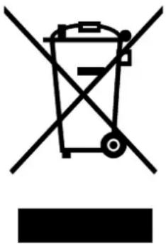
DISPOSAL: Do not dispose this product as unsorted municipal waste. Collection of such waste separately for special treatment is necessary.
It is prohibited to dispose of this appliance in domestic household waste.
For disposal, there are several possibilities:
A) The municipality has established collection systems, where electronic waste can be disposed of at least free of charge to the user.
B) When buying a new product, the retailer will take back the old product at least free of charge.
C) The manufacture will take back the old appliance for disposal at least free of charge to the user.
D) As old products contain valuable resources, they can be sold to scrap metal dealers.
Wild disposal of waste in forests and landscapes endangers your health when hazardous substances leak into the ground-water and find their way into the food chain.
natural_image
Symbol of a trash bin crossed with no text or numbers, representing waste sorting or disposal (no text present)To prevent injury to the user or other people and property damage, the following instructions must be followed. Incorrect operation due to ignoring of instructions may cause harm or damage.
■ The seriousness is classified by the following indications.
| WARNING | This symbol indicates the possibility of death or serious injury. |
| CAUTION | This symbol indicates the possibility of injury or damage to property. |
■ Meanings of symbols used in this manual are as shown below.
| Never do this. | |
| Always do this. |
WARNING
Connect with the power properly.
- Otherwise, it may cause electric shock or fire due to excess heat generation.
Do not modify power cord length or share the outlet with other appliances
- It may cause electric shock or fire due to heat generation.
Always ensure effective grounding.
- No groundiasse electric shock.
Disconnect the power if strange sounds, smell, or smoke comes from it.
- It may cause fire and electric shock.
Use the correctly rated breaker or fuse.
- There is risk of fire or electric shock.
① Ventilate room before operating air conditioner if there is a gas leakage from another appliance.
- It may cause explosion, fire and, burns.
Do not operate or stop the unit by switching on or off the power.
- It may cause electric shock or fire due to heat generation.
Do not operate with wet hands or in damp environment.
- It may cause electric shock.
Do not allow water to run into electric parts.
- It may cause failure of machine or electric shock.
Do not drink water drained from air conditioner.
- It contains contaminants and could make you sick.
Do not use the power cord close to heating appliances
- It may cause fire and electric shock.
Do not damage or use an unspecified power cord.
- It may cause electric shock or fire.
Do not direct airflow at room occupants only.
• This could damage your health.
Always install circuit breaker and a dedicated power circuit.
- No installation may cause fire and electric shock.
Do not open the unit during operation.
- It may cause electric shock.
Do not use the power cord near flammable gas or combustibles, such as gasoline, benzene, thinner, etc.
- It may cause an explosion or fire.
Do not disassemble or modify unit.
- It may cause failure and electric shock.
CAUTION
When the air filter is to be removed, do not touch the metal parts of the unit.
- It may cause an injury.
When the unit is to be cleaned, switch off, and turn off the circuit breaker.
- Do not clean unit when power is on as it may cause fire and electric shock, it may cause an injury.
Stop operation and close the window in storm or hurricane.
● Operation with windows opened may cause wetting of indoor and soaking of household furniture.
Do not use strong detergent such as wax or thinner. Use a soft cloth for cleaning.
● Appearance may be deteriorated due to change of product color or scratching of its surface.
Do not place heavy object on the power cord and take care so that the cord is not compressed.
- Do not operate your air conditioner in a wet room such as a bathroom or laundry room.
This appliance can be used by children aged from 8 years and above and persons with reduced physical, sensory or mental capabilities or lack of experience and knowledge if they have been given supervision or instruction concerning use of the appliance in a safe way and understand the hazards involved. Children shall not play with the appliance. Cleaning and user maintenance shall not be made by children without supervision.
Do not clean the air conditioner with water.
● Water may enter the unit and degrade the insulation. It may cause an electric shock.
Do not put a pet or house plant where it will be exposed to direct air flow.
● This could injure the pet or plant.
Do not place obstacles around air-inlets or inside of air-outlet.
- It may cause failure of appliance or accident.
① Ensure that the installation bracket of the outdoor appliance is not damaged due to prolonged exposure.
- If bracket is damaged, there is concern of damage due to falling of unit.
Use caution when unpacking and installing. Sharp edges could cause injury.
● Children should be supervised to ensure that they do not play with the appliance.
This appliance is not intended for use by persons (including children) with reduced physical, sensory or mental capabilities, or lack of experience and knowledge, unless they have been given supervision or instruction concerning use of the appliance by a person responsible for their safety.
Ventilate the room well when used together with a stove, etc.
• An oxygen shortage may occur.
Do not use for special purposes.
- Do not use this air conditioner to preserve precision devices, food, pets, plants, and art objects. It may cause deterioration of quality, etc.
Turn off the main power switch when not using the unit for a long time.
It may cause failure of product or fire.
Always insert the filters securely. Clean filter once every two weeks.
● Operation without filters may cause failure.
If water enters the unit, turn the unit off and disconnect the power, contact a qualified service technician.
● There is danger of fire or electric shock.
If the supply cord is damaged, it must be replaced by the manufacturer, its service agent or similarly qualified persons in order to avoid a hazard.
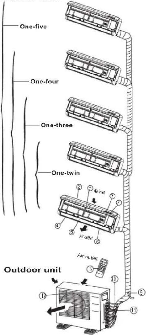
Identification of parts
Indoor unit

LED Display panel

(1)
Signal receptor

(2)
IMPORTANT:
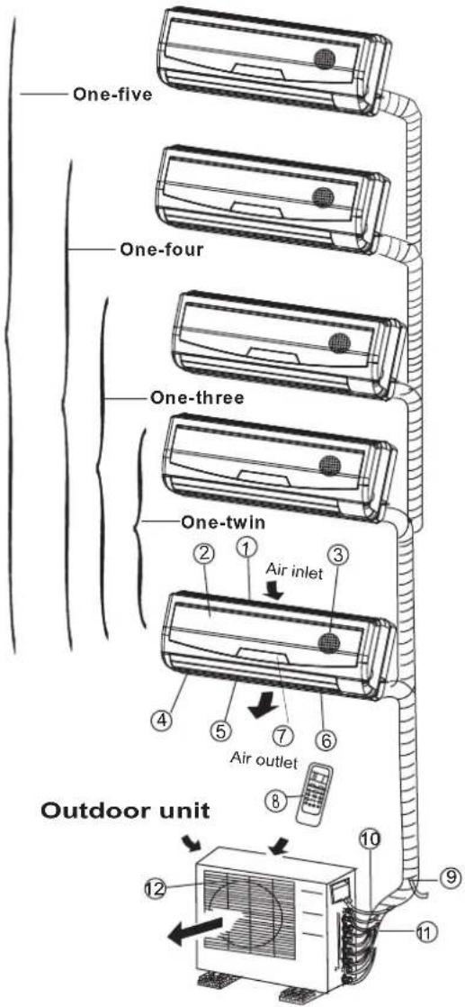
- For multi-split type air conditioner, one outdoor unit can match different types of indoor units. So all the pictures in this manual are for explanation purpose only. Your air conditioner may be slightly different. The actual shape shall prevail.
● The following pages introduce several kinds of indoor units matching with the outdoor units.
Indoor unit
- Front panel
- Top air intake
- Air filter(Inside)
- Air outlet
- Horizontal air flow louver
- Vertical air flow louver(Internal)
- Display panel
- LED display window
- Remote controller
- Manual control button(Behind the front panel)
Outdoor unit
- Refrigerant connecting pipe, drain hose and electric wiring
- Stop valve
- Air outlet
Display panel
AUTO indication lamp
Lights up during the Auto operation.
TIMER indication lamp
Lights up during Timer operation.
DEFROST indication lamp
(For Cooling & Heating models only): Lights up when the air conditioner starts defrosting automatically or when the warm air control feature is activated in heating operation.
DIGITAL DISPLAY indication lamp
Displays the current setting temperature. Only when the air conditioner is in FAN operation, it displays the actual room temperature. And displays the malfunction code or protection code.
OPERATION indication lamp
This indicator appears only when the compressor is in operation and indicates the current operating frequency.
Identification of parts
Indoor unit

DISPLAY PANEL

Indoor unit
① Front panel frame
② Front panel
③ Air filter
④ Horizontal air flow grille
⑤ Vertical air flow louver
⑥ Room temperature sensor
⑦ Display panel
⑧ Infrared signal receiver
⑨ Remote controller
Outdoor unit
⑩ Drain hose, refrigerant connecting pipe
⑪ Connective cable
⑫ Stop valve
⑬ Fan hood
DISPLAY PANEL
OPERATION indicator:
The indicator flashes once every second after power is on and illuminates when the air conditioner is in operation.
TIMER indicator:
The indicator illuminates when TIMER is set ON.
PRE-DEF. Indicator (For cooling& heating model only):
This indicator illuminates when the air conditioner starts defrosting automatically or when the Anti-cold air function is activated in heating operation.
AUTO indicator:
This indicator flashes when the air conditioner is in AUTO operation.
Identification of parts
Indoor unit
LED Display window

(1)
(2)
Indoor unit
① Front panel frame
② Front panel
③ Air filter
④ Horizontal air flow grille
⑤ Vertical air flow louver
⑥ Room temperature sensor
⑦ Display panel
⑧ Remote controller
Outdoor unit
⑨ Drain hose, refrigerant connecting pipe
⑩ Connective cable
⑪ Stop valve
⑫ Fan hood
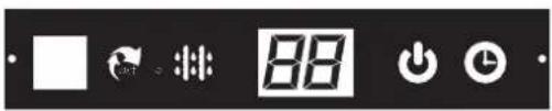
LED DISPLAY WINDOW
① AUTO indication lamp
Lights up during the Auto operation.
② TIMER indication lamp
Lights up during Timer operation.
③ DEFROST indication lamp
(For Cooling & Heating models only):
Lights up when the air conditioner starts defrosting automatically or when the warm air control feature is activated in heating operation.
④ DIGITAL DISPLAY indication lamp
Displays the current setting temperature. Only when the air conditioner is in FAN operation, it displays the actual room temperature. And displays the malfunction code or protection code.
⑤ OPERATION indication lamp
This indicator appears only when the compressor is in operation and indicates the current operating frequency.
Identification of parts
Indoor unit

Display window
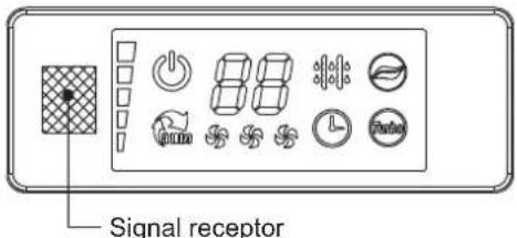
NOTE: The display window on the air conditioner you purchased may look like one of the following:

(1)
Indoor unit
- Panel frame
- Rear air intake grille
- Front panel
- Air Purifying filter & Air filter(behind)
- Horizontal louver
- LCD display window
- Vertical louver
- Manual control button (behind)
- Remote controller holder
Outdoor unit
- Drain hose, refrigerant connecting pipe
- Connective cable
- Stop valve
- Fan hood
(2)

(3)

(4)

natural_image
Row of eight icons including a battery, bar chart, 88 blocks, camera, walking, shoe, and square (no text or symbols)(5)

(6)

(7)

OPERATION display
Displayed when the air conditioner is in operation.

AUTO operation display
Displayed during Auto operation.

DEFROST operation display
(For Heating & Cooling model only): Displayed when the air conditioner starts defrosting automatically or when the warm air control feature is activated in heating operation.

TIMER display
Displayed during Timer operation.

CLEAN AIR display(optional)
Displayed when CLEAN AIR feature is activated.

TURBO operation display
Displayed when select TURBO function on cooling operation or on heating operation.

DIGITAL DISPLAY
Displays the current setting temperature when the air conditioner is in operation.

FAN SPEED display
Displayed the selected fan speed: LOW( ), MED( ) and HIGH( ).

Frequency indication lamp
This display is separated into five zones. The zones illuminate based on the compressor current frequency. For example, higher frequency will illuminate more zones.
Identification of parts
Indoor unit
LED Display window

Indoor unit
- Front panel
- Air inlet
- Air filter
- Air outlet
- Horizontal air flow grille
- Vertical air flow louver(inside)
- Display panel
- Remote control
NOTE: The actual shape of the indoor unit you purchased may may be slight different on front panel and display window.
Outdoor unit
- Drain hose, refrigerant connecting pipe
- Connective cable
- Stop valve
- Fan hood
NOTE:
All the pictures in this manual are for explanation purposes only. Your air conditioner may be slightly different. The actual shape shall prevail.
Indication lamp on LED Display window

ION indication lamp(optional function)
This lamp illuminates when Clean Air feature is activated.

DEFROST indication lamp
(Enabled on cooling & heating models only): Lights up when the air conditioner starts defrosting automatically or when the warm air control feature is activated in heating operation.

OPERATION indication lamp
This lamp illuminates when the air conditioner is in operation.

TIMER indication lamp
Lights up during Timer operation.

Temperature indicator
- Displays the temperature settings when the air conditioner is operational.
• Displays the malfunction code.
Identification of parts
Indoor unit

LED Display window

natural_image
Six abstract line drawings including geometric shapes, eye, clock, leaf, and textured surfaces (no text or symbols)Indoor unit
- Front panel
- Air inlet
- Air filter(inside)
- Air outlet
- Horizontal air flow grille(outside)
- Horizontal air flow grille(inside)
- Vertical air flow louver
- Display panel
- Manual control button and receiver
- Intelligent eye detector(on some models)
Outdoor unit
- Drain hose, refrigerant connecting pipe
- Connective cable
- Stop valve
- Fan hood
NOTE:
All the pictures in this manual are for explanation purposes only. Your air conditioner may be slightly different. The actual shape shall prevail.
Indication lamp on LED Display window

TEMPERATURE indication lamp
Displays the temperature settings when the air conditioner is operational. Displays the malfunction code. Displays the actual room temperature on Fan only mode.

INTELLIGENT EYE indication lamp (Optional)
Lights up during Intelligent eye operation except when the machine is defrosting. This indication lamp continues flashing when the unit detects human activity.

TIMER indication lamp
Lights up during Timer operation.

ION indication lamp(optional)
Lights up when Clean Air feature is activated.

DEFROST indication lamp
(Enabled on cooling & heating models only): Lights up when the air conditioner starts defrosting automatically or when the warm air control feature is activated in heating operation.
Identification of parts
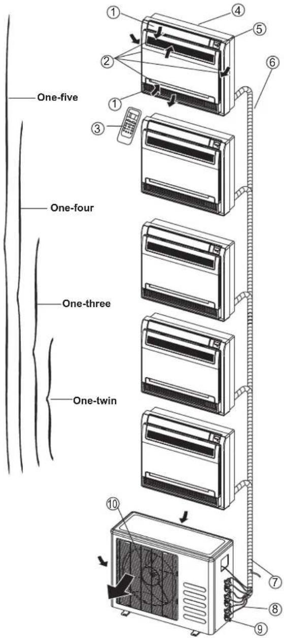
Floor and standing type(console) Indoor unit
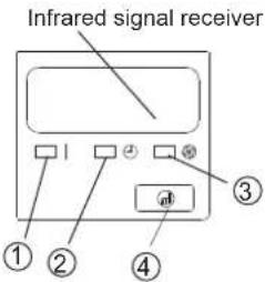
Display panel
Indoor unit
- Air flow louver (at air outlet)
- Air inlet(with air filter in it)
- Remote controller
- Installation part
- Display panel
- Connecting pipe
Outdoor unit
- Drain hose, refrigerant connecting pipe
- Connective cable
- Stop valve
- Fan hood
DISPLAY PANEL:
① OPERATION indication lamp
This indicator illuminates when the unit is operational.
② TIMER indication lamp
Lights up during Timer operation.
③ DEFROST indication lamp(Cooling & Heating models only) or Fan only indication lamp (Cooling only type): Lights up when the air conditioner starts defrosting automatically in heating operation or fan only mode is selected.
④ Temporary button
This button is used to operate the unit temporarily in case you misplace the remote controller or its batteries are exhausted. One press of the manual control button will lead to the forced AUTO operation. If press the button twice within five seconds, the unit will operate under forced COOL operation. The forced COOL operation is used for testing purposes only, please do not choose it unless it is necessary.
Identification of parts
Floor and standing type(console) Indoor unit
Display panel
NOTE: The display window on the air conditioner you purchased may look like one of the following:
(1)
Indoor unit
- Indoor unit
- Air flow louver (at air outlet)
- Installation part
- Air out
- Air inlet(with air filter in it)
- Air in
- Remote controller
Outdoor unit
- Drain hose, refrigerant connecting pipe
- Connective cable
- Stop valve
- Fan hood
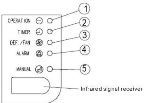
DISPLAY PANEL:
① OPERATION indication lamp
This indicator illuminates when the unit is operational.
② TIMER indication lamp
Lights up during Timer operation.
③ DEF./FAN indication lamp
Lights up when the air conditioner starts defrosting automatically in heating operation (applicable to cooling & heating models only) or fan only mode is selected(applicable to cooling only models).
④ AIARM indication lamp
Flashes when malfunction occurs.

(2)

(3)

(4)

(5)
⑤ Temporary button
This button is used to operate the unit temporarily in case you misplace the remote controller or its batteries are exhausted. One press of the manual control button will lead to the forced AUTO operation. If press the button twice within five seconds, the unit will operate under forced COOL operation. The forced COOL operation is used for testing purposes only, please do not choose it unless it is necessary.
⑥ Temperature Display
Displays the current setting temperature while the unit is operating.
Identification of parts
Duct / Ceiling type
Indoor unit

Display panel
Indoor unit
- Air outlet
- Air inlet
- Air filter
- Electric control cabinet
- Wire controller
- Drain pipe
Outdoor unit
- Drain hose, refrigerant connecting pipe
- Connective cable
- Stop valve
- Fan hood
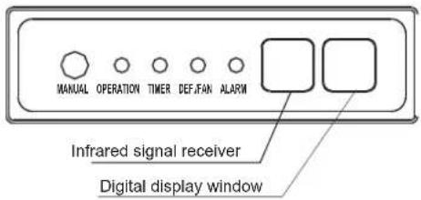
DISPLAY PANEL:
① OPERATION indication lamp
This indicator illuminates when the unit is operational.
② TIMER indication lamp
Lights up during Timer operation.
③ DEF./FAN indication lamp
Lights up when the air conditioner starts defrosting automatically in heating operation (applicable to cooling & heating models only) or fan only mode is selected(applicable to cooling only models).
④ AIARM indication lamp
Flashes when malfunction occurs.
⑤ MANUAL button
This button is used to operate the unit temporarily in case you misplace the remote controller or its batteries are exhausted. One press of the manual control button will lead to the forced AUTO operation. If press the button twice within five seconds, the unit will operate under forced COOL operation. The forced COOL operation is used for testing purposes only, please do not choose it unless it is necessary.
Identification of parts
Duct type
Indoor unit

Display panel

Indoor unit
- Air outlet
- Air inlet
-
Air filter
-
Remote controller
Outdoor unit
- Drain hose, refrigerant connecting pipe
- Connective cable
- Stop valve
- Fan hood
DISPLAY PANEL:
① OPERATION lamp
This indicator illuminates when the unit is operational.
② TIMER indication lamp
Lights up during Timer operation.
③ PRE-DEF./FAN indication lamp
Lights up when the air conditioner starts defrosting automatically in heating operation (applicable to cooling & heating models only) or fan only mode is selected(applicable to cooling only models).
④ AIARM indication lamp
Flashes when malfunction occurs.
⑤ TEMPORARY button
This button is used to operate the unit temporarily in case you misplace the remote controller or its batteries are exhausted. One press of the manual control button will lead to the forced AUTO operation. If press the button twice within five seconds, the unit will operate under forced COOL operation. The forced COOL operation is used for testing purposes only, please do not choose it unless it is necessary.
OPERATING INSTRUCTIONS
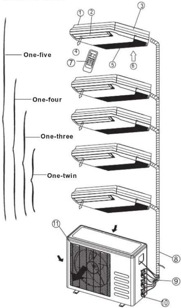
Identification of parts Compact four-way cassette type Indoor unit

One-four
One-three
One-twin
11
11
12
Display panel
Infrared signal receiver
Temporary button
Operation lamp
Timer indicator
Alarm indicator
PRE-DEF indicator(cooling and heating type)
or fan only indicator(cooling only type)
Indoor unit
- Air flow louver(at air outlet)
- Drain pump(drain water from indoor unit)
- Drain pipe
- Air outlet
- Air filter(inside air-in grill)
- Air inlet
- Air-in grill
- Display panel
- Remote controller
- Refrigerant pipe
Outdoor unit
- Air inlet
- Air outlet
DISPLAY PANEL:
1 OPERATION lamp
This indicator illuminates when the unit is operational.
2 TIMER indication lamp
Lights up during Timer operation.
3 PRE-DEF./FAN indication lamp
Lights up when the air conditioner starts defrosting automatically in heating operation (applicable to cooling & heating models only) or fan only mode is selected(applicable to cooling only models).
4 AIARM indication lamp
Flashes when malfunction occurs.
5 TEMPORARY button
This button is used to operate the unit temporarily in case you misplace the remote controller or its batteries are exhausted. One press of the manual control button will lead to the forced AUTO operation. If press the button twice within five seconds, the unit will operate under forced COOL operation. The forced COOL operation is used for testing purposes only, please do not choose it unless it is necessary.
NOTE: This manual does not include Remote Controller Operations, see the <
Operating temperature
| ModeTemperature | Cooling operation | Heating operation | Drying operation |
| Room temperature | 17°C32 62C(°F~90°F) | 0°C30 2°C(3 °F~86°F) | 17°C~32°C(62°F~90°F) |
| Outdoor temperature | 0°C~50°C(32°F~122°F) | -15°C~24°C(5°F~76°F) | 0°C~50°C(32°F~122°F) |
| (-15°C~50°C/ 5°F~122°F: For the models with low temperature cooling system ) | |||
| NOTE:1. Optimum performance will be achieved within these operating temperatures.If air conditioner is used outside of the above conditions, certain safety protection features might come into operation and cause the unit to function abnormally.2. If the air conditioner operates in a room whose relative humidity is less than 80% the surface of the air conditioner may attract condensation. Please sets the vertical air flow louver to its maximum angle (vertically to the floor), and set HIGH fan mode.Suggestion:For the unit adopts an Electric Heater, when the outside ambient temperature is below 0°C(32°F), we strongly recommend you to keep the machine plugged in order to guarantee it running smoothly. | |||
Manual operation
Manul operation can be used temporarily in case you can not find the remote controller or test running purpose or maintenance necessary.

NOTE: The unit must be turned off before operating the manual control button. If the unit is operational, continue pressing the manual control button until the unit is off.
① Open and lift the front panel up will see the manual control button(see Model A)
For some models, the manual control button is located at the bottom of the unit(see Model B).
② One press of the manual control button will lead to the forced AUTO operation. If press the button twice within five seconds, the unit will operate under forced COOL operation.
③ Close the panel firmly to its original position.
NOTE: For DUCT and CEILING type, CASSETTE type, CEILING and FLOOR type and FLOOR and STANDING type, please refer to the previous pages to operate the Manual button.
Airflow direction control
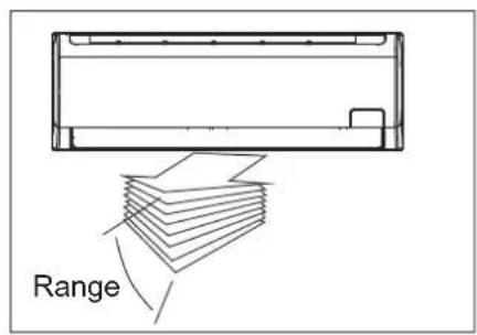
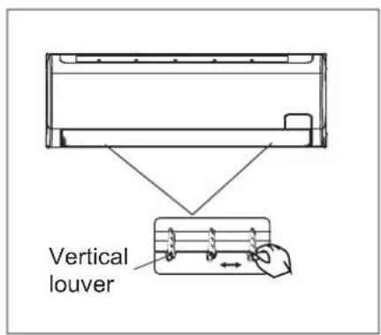
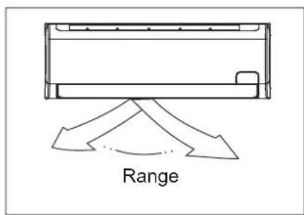
- Adjust the air flow direction properly otherwise it might cause discomfort or cause uneven room temperatures.
- Adjust the horizontal/vertical louver using the remote controller. For some models, the vertical louver can only be adjusted manually.
To set the horizontal/vertical air flow direction
- Perform this function while the unit is in operation.
- Use the remote controller to adjust the air flow direction. The vertical/horizontal louver changes 6 degree in angle for each press, or swing up and down automatically. Please refer to the 'REMOTE CONTROLLER OPERATION MANUAL' for details.
- For some models, the vertical louver can only be adjusted manually. Move the deflector rod manually to adjust the air flow in the direction you prefer.
IMPORTANT: Do not put your fingers into the panel of blower and suction side. The high-speed fan inside may cause danger.

CAUTION
- Do not operate the air conditioner for long periods with the air flow direction set downward in cooling or dehumidifying mode. Otherwise, condensation may occur on the surface of the horizontal louver causing moisture to drop on to the floor or on furnishings.
- Do not move the horizontal louver manually unless it is necessary. Always use the remote controller.
- When the air conditioner is started immediately after it was stopped, the horizontal louver might not move for approximately 10 seconds.
- Open angle of the horizontal louver should not be set too small, as COOLING or HEATING performance may be impaired due to too restricted air flow area.
- Do not operate unit with horizontal louver in closed position.
- When the air conditioner is connected to power (initial power), the horizontal louver may generate a sound for 10 seconds, this is a normal operation.
Duct-Ceiling Type
The following is how to adjust the air flow direction when the air outlet parts (sold separately) is used with the indoor unit.
Cooling
To effectively cool the whole room, please adjust the louver horizontally.

natural_image
Simple line drawing of a container with internal vertical lines and two arrows indicating flow or movement (no text or symbols)Heating
To effectively heat the bottom of the room please set the louver downwards.

natural_image
Simple line drawing of a rectangular frame with vertical internal lines and diagonal markings (no text or symbols)Ceiling-Floor Type
Auto-swing
Press SWING button, the louver will swing up and down(left and right) automatically.
Manual Swing
Adjust the louver to achieve better cooling/heating effects when cooling/heating.

natural_image
Diagram of a mechanical component with directional arrows indicating motion or force (no text or symbols)When cooling
Adjust the louver horizontally.

natural_image
Pure technical line drawing of a mechanical component without any text, numbers, or symbolsWhen heating
Adjust the louver downwards (vertically).

natural_image
Pure technical diagram showing a mechanical component with an arrow indicating direction (no text or symbols)NOTE : The heating operation with horizontal air out let will increase the difference of the room temperature.
| !Notice Notice the louver direction | ! | Choose horizontal outlet mode when cooling operationUnder cooling operation ,the air flow down will cause condensing dew on the air outlet and louver surface. |
How the air conditioner works

Cooling

flowchart
graph TD
    A["Set Temperature"] --> B["1°C"]
    B --> C["1°C"]
    C --> D["7 hours timer off"]
    style A fill:#f9f,stroke:#333
    style B fill:#ccf,stroke:#333
    style C fill:#cfc,stroke:#333
    style D fill:#fcc,stroke:#333
Heating
AUTO operation
- When you set the air conditioner in AUTO mode, it will automatically select cooling, heating(cooling /heating models only), or fan only operation depending on what temperature you have selected and the room temperature.
- The air conditioner will control room temperature automatically round the temperature point set by you.
- If the AUTO mode is uncomfortable, you can select desired conditions manually.
SLEEP operation
- When you push SLEEP button on remote controller during cooling, heating(cooling only type without), or AUTO operation, the air conditioner will automatically increase (cooling) or decrease (heating) 1°C per hour.
- The set temperature will be steady 2 hours later. And the air conditioner will be timer off in 7 hours.
- The fan speed will be automatically controlled.
- This feature can maintain the most comfortable temperature and save more energy for you.
DRYING operation
- The fan speed will be automatically controlled under dry operation.
- During the dry operation, if the room temperature is lower than 10°C, the compressor stops operation and restarts until the room temperature is above 12°C.
Operation mode selection
While simultaneously operating two indoor units or more, make sure the operation modes will not conflict with each other. The heat mode claims precedence over all other modes. If the unit initially started operates under heat mode, the other units can operate under heat mode only.
For example: If the unit initially started operates under cool(or fan) mode, the other units can operate under any mode except heat. If one of the unit selects heat mode, the other operating units will stop operation and display "P5" (For the units with display window only) or the Auto and Operation indication light flash rapidly, the Defrost indication light turn off, the Timer indication light remain on (For the units without display window), or the Defrost and Alarm indication light (if applicable) illuminate, the Operation indication light flashes rapidly and the Timer indication light turns off ( For the Floor and standing type).
Optimal operation
To achieve optimal performance, please note the following:
- Adjust the air flow direction correctly so that it is not directed on people.
- Adjust the temperature to achieve the highest comfort level. Do not adjust the unit to excessive temperature levels.
- Close doors and windows on COOL or HEAT modes, or performance may be reduced.
- Use TIMER ON button on the remote controller to select a time you want to start your air conditioner.
- Do not put any object near air inlet or air outlet, as the efficiency of the air conditioner may be reduced and the air conditioner may stop running.
- Clean the air filter periodically, otherwise cooling or heating per formance may be reduced.
- Do not operate unit with horizontal louvre in closed position.
Suggestion: For the unit adopts an Electric Heater, when the outside ambient temperature is below 0^ C, we strongly recommend you to keep the machine plugged in order to guarantee it running smoothly.
Care and maintenance

natural_image
Illustration of two hands holding a rectangular device with internal components, no text or symbols present

natural_image
Diagram showing a hand pressing down a curved panel with a downward arrow (no text or symbols)Cleaning the Grille, Case and Remote Controller
- Turn the system off before cleaning. To clean, wipe with a soft, dry cloth. Do not use bleach or abrasives.
NOTE: Supply power must be disconnect before cleaning the indoor unit.
CAUTIONS
- A cloth dampened with cold water may be used on the indoor unit if it is very dirty. Then wipe it with a dry cloth.
- Do not use a chemically treated cloth or duster to clean the unit.
- Do not use benzine, thinner, polishing powder, or similar solvents for cleaning. These may cause the plastic surface to crack or deform.
- Never use water hotter than 40 C to clean the front panel, it could cause deformation of discoloration.
■ WALL-MOUNTED TYPE
Cleaning the air filter
A clogged air filter reduces the cooling efficiency of this unit. Please clean the filter once every 2 weeks.
-
Lift the indoor unit panel up to an angle until it stops with a clicking sound.
-
Take hold of the handle of the air filter and lift it up slightly to take it out from the filter holder, then pull it downwards.
-
Remove the Active Carbon & Dust Filter from the indoor unit.
-
Clean the it once two weeks.
- Clean the it with a vacuum cleaner or water, then dry it up in cool place.


natural_image
Illustration of two hands inserting a grid into an abacus (no text or symbols)
natural_image
Line drawing of a hand opening a car air vent with a grid-patterned vent (no text or symbols)- Remove the Air Freshening Filter(Optional filter:
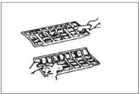
Plasma Dust collector/Silver Ion filter /Bio filter /Vitamin C filter) from its support frame.
(The installation and removing method of the air freshening filter is different depending on the models, see the pictures marked ① and ② on the left.
- Clean the air freshening filter at least once a month, and replace it every 4-5 months.
-
Clean it with vacuum cleaner, then dry it in cool place.
-
Install the air freshening filter back into position.
-
Insert the upper portion of air filter back into the unit taking care that the left and right edges line up correctly and place filter into position.
Maintenance
If you plan to idle the unit for a long time, perform the following:
(1) Operate the fan for about half a day to dry the inside of the unit.
(2) Stop the air conditioner and disconnect power. Remove the batteries from the remote controller.
(3) The outdoor unit requires periodic maintenance and cleaning. Do not attempt to do this yourself. Contact your dealer or servicer.
Checks before operation
- Check that the wiring is not broken off or disconnected.
- Check that the air filter is installed.
- Check if the air outlet or inlet is blocked after the air conditioner has not been used for a long time.

Caution
- Do not touch the metal parts of the unit when removing the filter. Injuries can occur when handling sharp metal edges.
- Do not use water to clean inside the air conditioner. Exposure to water can destroy the insulation, leading to possible electric shock.
- When cleaning the unit, first make sure that the power and circuit breaker are turned off.
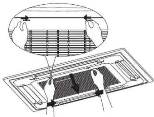
Fig. A

natural_image
Technical line drawing of a mechanical component with internal structure and an inset view (no text or symbols)Fig.B

natural_image
Simple line drawing of a hand holding a fish-shaped object next to a grid-patterned surface (no text or symbols)Fig. C

natural_image
Simple line drawing of a hand using a tool to press or write on a grid-patterned surface (no text or symbols)Fig. D
■ CASSETTE TYPE
- Open the air-in grill
Push the grill switches towards the middle simultaneously as indicated in Fig. A. Then pull down the air-in grill.
Cautions: The control box cables, which are originally connected with the main body electrical terminators must be pulled off before doing as indicated above.
- Take out the air-in grill (together with the air filter shown in Fig. B). Pull the air-in grill down at 45° and lift it up to take out the grill.
- Dismantle the air filter
- Clean the air filter(Vacuum cleaner or pure water may be used to clean the air filter. If the dust accumulation is too heavy, please use soft brush and mild detergent to clean it and dry out in cool place).
■ DUCT AND CEILING TYPE
- Open the air-in grill
Push the grill switches towards the middle simultaneously as indicated in follow figure sketch. Then pull down the air-in grill.
Cautions: The control box cables, which are originally connected with the main body electrical terminators must be pulled off before doing as indicated above.
- Take out the air-in grill.
- Dismantle the air filter
-
Clean the air filter (Vacuum cleaner or pure water may be used to clean the air filter. If the dust accumulation is too heavy, please use soft brush and mild detergent to clean it and dry out in cool place).
-
The air-in side should face up when using vacuum cleaner. (See Fig. C)
- The air-in side should face down when using water. (See Fig. D)
Cautions : Do not dry out the air filter under direct sunshine or with fire.
- Re-install the air filter
- Install and close the air-in grill in the reverse order of step 1 and 2 and connect the control box cables to the corresponding terminators of the main body.
Note: High-static Pressure Parvis Split Type has no air filter.

Fig.E1


natural_image
Technical line drawing of a structural component with internal channels and directional arrows (no text or symbols)Fig.E3

natural_image
Diagram of a server rack with two arrows indicating cable or connector (no text or symbols present)Fig.F1
■ CEILING AND FLOOR TYPE
For ≤36000Btu/h models
- Open the air intake (see Fig.E1).
- Take out the air filter(see Fig.E2).
- Clean the air cleaning filter with water or vacuum cleaner, then dry it in cool place.
- Re-install the air filter in the reverse order of Fig.E2.
For ≥48000Btu/h models
- Directly pull out the air filter from air inlet as indicated in Fig.E3.
- Clean the air cleaning filter with water or vacuum cleaner, then dry it in cool place.
- Re-install the air filter in the reverse order of Fig.E3.
■ FLOOR AND STANDING TYPE(Console)
- Open the front panel.(Refer to Fig. F1)

Fig.F2

Fig.F3

natural_image
Line drawing of a vacuum cleaner emitting exhaust air onto a grid-patterned surface (no text or symbols)Fig.F4

natural_image
Simple line drawing of a faucet spraying water into a grid-patterned container (no text or symbols)Fig.F5
2. Remove the air filter
Press the claws on the right and left of the air filter down slightly, then pull upward.(Refer to Fig.F2)
3. Take off the especial function filter
Hold the tabs of the frame, and remove the claws in 4 places. (Refer to Fig. F3)
(The expecial function filter can be renewed by washing it with water once every 6 months. We recommend replacing it once every 3 years.)
4. Clean the air filter
Vacuum cleaner or pure water may be used to clean the air filter. If the dust accumulation is too heavy, please use soft brush and mild detergent to clean it and dry out in cool place.
The air-in side should face up when using vacuum cleaner.(see Fig.F4)
The air-in side should face down when using water (see Fig. F5).
5. Set the air filter and the especial function filter as they were and close the front panel.
Operation without air filters may result in troubles as dust will accumulate inside the indoor unit.
CAUTION:
Do not dry the air filter by heat or under the direct sunlight.

natural_image
Technical line drawing of a mechanical device with internal components and mounting holes (no text or symbols)Fig.G1
natural_image
Technical line drawing of a mechanical device with internal components and a magnified inset showing a detail (no text or symbols)Fig.G2

natural_image
Line drawing of a vacuum cleaner emitting exhaust from a grid-patterned surface (no text or symbols)Fig.G3
natural_image
Simple line drawing of a faucet pouring liquid into a grid (no text or symbols)Fig.G4
■ DUCT /CEILING TYPE
- For the unit is a rear ventilated one, please remove the screws (2 pieces) fixed on the filter and take down the filter away from the unit. See Fig.G1.
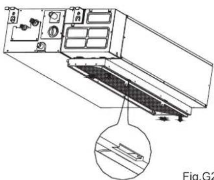
- For the unit is a descensional ventilated one, please push the filter up slightly to let the position retainer escape away from the flange fixed holes, and take off the filter according to the arrow direction shows in the Fig.G2.
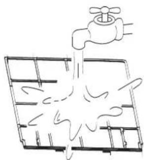
- Clean the air filter. Vacuum cleaner or pure water may be used to clean the air filter. If the dust accumulation is too heavy, please use soft brush and mild detergent to clean it and dry out in cool place.
- The air-in side should face up when using vacuum cleaner.(see Fig.G3) The air-in side should face down when using water (see Fig. G4).
Maintenance
If you plan to idle the unit for a long time, perform the following:
- Clean the indoor unit and air filter.
- Select FAN only mode, let the indoor fan run for a while to dry the inside of the unit.
- Disconnect the power supply and remove battery from the remote control.
- Check components of the outdoor unit periodically. Contact a local dealer or a customer service centre if the unit requires servicing.
Note: Before you clean the air conditioner, be sure to switch the unit off and disconnect the power supply plug.
When the air conditioner is to be used again:
- Use a dry cloth to wipe off the dust accumulated on rear air intake grille, in order to avoid the dust blowing out from the indoor unit.
- Check that the wiring is not broken off or disconnected.
- Check that the air filter is installed.
- Check if the air outlet or inlet is blocked after the air conditioner has not been used for a long time.
Operation Tips
The following events may occur during normal operation.
1. Protection of the air conditioner. Compressor protection
- The compressor can't restart for 3 minutes after it stops.
- The unit is designed not to blow cold air on HEAT mode, when the indoor heat exchanger is in one of the following three situations and the set temperature has not been reached.
Anti-cold air (Cooling and heating models only)
A) When heating has just starting.
B) Defrosting.
C) Low temperature heating.
- The indoor or outdoor fan stop running when defrosting (Cooling and heating models only).
Defrosting (Cooling and heating models only)
- Frost may be generated on the outdoor unit during heat cycle when outdoor temperature is low and humidity is high resulting in lower heating efficiency of the air conditioner.
- During this condition air conditioner will stop heating operation and start defrosting automatically.
- The time to defrost may vary from 4 to 10 minutes according to the outdoor temperature and the amount of frost buildup on the outdoor unit.
2. A white mist coming out from the indoor unit
- A white mist may generate due to a large temperature difference between air inlet and air outlet on COOL mode in an indoor environment that has a high relative humidity.
- A white mist may generate due to moisture generated from defrosting process when the air conditioner restarts in HEAT mode operation after defrosting.
3. Low noise of the air conditioner
- You may hear a low hissing sound when the compressor is running or has just stopped running. This sound is the sound of the refrigerant flowing or coming to a stop.
- You can also hear a low "squeak" sound when the compressor is running or has just stopped running. This is caused by heat expansion and cold contraction of the plastic parts in the unit when the temperature is changing.
-
A noise may be heard due to louver restoring to its original position when power is first turned on.
-
Dust is blown out from the indoor unit.
This is a normal condition when the air conditioner has not been used for a long time or during first use of the unit.
- A peculiar smell comes out from the indoor unit.
This is caused by the indoor unit giving off smells permeated from building material, from furniture, or smoke.
- The air conditioner turns to FAN only mode from COOL or HEAT (For cooling and heating models only) mode.
When indoor temperature reaches the temperature setting on air conditioner, the compressor will stop automatically, and the air conditioner turns to FAN only mode. The compressor will start again when the indoor temperature rises on COOL mode or falls on HEAT mode (For cooling and heating models only) to the set point.
-
Dripping water may generate on the surface of the indoor unit when cooling in a high relatively humidity (relative humidity higher than 80%). Adjust the horizontal louver to the maximum air outlet position and select HIGH fan speed.
-
Heating mode (For cooling and heating models only)
The air conditioner draws in heat from the outdoor unit and releases it via the indoor unit during heating operation. When the outdoor temperature falls, heat drawn in by the air conditioner decreases accordingly. At the same time, heat loading of the air conditioner increases due to larger difference between indoor and outdoor temperature. If a comfortable temperature can't be achieved by the air conditioner, we suggest you use a supplementary heating device.
- Auto-restart function
Power failure during operation will stop the unit completely.
For the unit without Auto-restart feature, when the power restores, the OPERATION indicator on the indoor unit starts flashing. To restart the operation, push the ON/OFF button on the remote controller. For the unit with Auto-restart feature, when the power restores, the unit restarts automatically with all the previous settings preserved by the memory function.
- Lightning or a car wireless telephone operating nearby may cause the unit to malfunction.
Disconnect the unit with power and then re-connect the unit with power again. Push the ON/OFF button on the remote controller to restart operation.
| Stop the air conditioner immediately if one of the following faults occur. Disconnect the power and contact the nearest customer service center. | |
| Trouble | If the E( 0,1......) or P( 0, 1 ......) code appears on the LED(LCD)window, disconnect the power and contact the service people. |
| Fuse blows frequently or circuit breaker trips frequently. | |
| Other objects or water penetrate the air conditioner. | |
| The remote controller won't work or works abnormally. | |
| Other abnormal situations. | |
| Malfunctions | Cause | What should be done? |
| Unit does not start | Power cut | Wait for power to be restored. |
| Unit may have become unplugged. | Check that plug is securely in wall receptacle. | |
| Fuse may have blown. | Replace the fuse. | |
| Battery in Remote controller may have been exhausted. | Replace the battery. | |
| The time you have set with timer is incorrect. | Wait or cancel timer setting. | |
| Unit not cooling or heating (Cooling/ heating models only) room very well while air flowing out from the air conditioner | Inappropriate temperature setting. | Set temperature correctly. For detailed method please refer to "Remote controller instruction" section. |
| Air filter is blocked. | Clean the air filter. | |
| Doors or Windows are open. | Close the doors or windows. | |
| Air inlet or outlet of indoor or outdoor unit has been blocked. | Clear obstructions away first, then restart the unit. | |
| Compressor 3 minutes protection has been activated. | Wait. | |
| If the trouble has not been corrected, please contact a local dealer or the nearest customer service center. Be sure to inform them of the detailed malfunctions and unit model. | ||
Notes: Do not attempt to repair the unit yourself.
Always consult an authorised service provider.
The design and specifications are subject to change without prior notice for product improvement. Consult with the sales agency or manufacturer for details.
CS464-U2
202000191054
20130702
- ROOM AIR CONDITIONER
- USER'S MANUAL
- Read This Manual
- CONTENTS
- SOCIABLE REMARK
- SAFETY PRECAUTIONS
- OPERATING INSTRUCTIONS
- CARE AND MAINTENANCE
- OPERATION TIPS
- TROUBLESHOOTING TIPS
- CAUTION
- WARNING
- Identification of parts
- IMPORTANT:
- Indoor unit
- Outdoor unit
- Display panel
- AUTO indication lamp
- TIMER indication lamp
- DEFROST indication lamp
- DIGITAL DISPLAY indication lamp
- OPERATION indication lamp
- OPERATION indicator:
- TIMER indicator:
- PRE-DEF. Indicator (For cooling& heating model only):
- AUTO indicator:
- LED DISPLAY WINDOW
- Display window
- OPERATION display
- AUTO operation display
- DEFROST operation display
- TIMER display
- CLEAN AIR display(optional)
- TURBO operation display
- DIGITAL DISPLAY
- FAN SPEED display
- Frequency indication lamp
- NOTE:
- Indication lamp on LED Display window
- ION indication lamp(optional function)
- Temperature indicator
- TEMPERATURE indication lamp
- INTELLIGENT EYE indication lamp (Optional)
- ION indication lamp(optional)
- Floor and standing type(console) Indoor unit
- DISPLAY PANEL:
- ⑤ Temporary button
- ⑥ Temperature Display
- ① OPERATION indication lamp
- ② TIMER indication lamp
- ③ DEF./FAN indication lamp
- ④ AIARM indication lamp
- ⑤ MANUAL button
- Duct type
- ① OPERATION lamp
- ③ PRE-DEF./FAN indication lamp
- Identification of parts Compact four-way cassette type Indoor unit
- Manual operation
- Airflow direction control
- To set the horizontal/vertical air flow direction
- Duct-Ceiling Type
- Cooling
- Heating
- Ceiling-Floor Type
- Auto-swing
- Manual Swing
- When cooling
- When heating
- How the air conditioner works
- AUTO operation
- SLEEP operation
- DRYING operation
- Operation mode selection
- Optimal operation
- Cleaning the Grille, Case and Remote Controller
- CAUTIONS
- ■ WALL-MOUNTED TYPE
- Cleaning the air filter
- Maintenance
- Checks before operation
- ■ CASSETTE TYPE
- ■ DUCT AND CEILING TYPE
- ■ CEILING AND FLOOR TYPE
- For ≤36000Btu/h models
- For ≥48000Btu/h models
- ■ FLOOR AND STANDING TYPE(Console)
- Remove the air filter
- Take off the especial function filter
- Clean the air filter
- Set the air filter and the especial function filter as they were and close the front panel.
- CAUTION:
- ■ DUCT /CEILING TYPE
- When the air conditioner is to be used again:
- Protection of the air conditioner. Compressor protection
- Anti-cold air (Cooling and heating models only)
- Defrosting (Cooling and heating models only)
- A white mist coming out from the indoor unit
- Low noise of the air conditioner
Brand : Maxicool
Model : LMD-M12
Category : Air conditioner