
Escape Hybrid (2008) - Automobile FORD - Free user manual and instructions
Find the device manual for free Escape Hybrid (2008) FORD in PDF.


| Product Type | Compact Hybrid SUV |
| Manufacturer | Ford Motor Company |
| Model Year | 2008 |
| Engine | 2.5L Atkinson-cycle I4 (gasoline) + electric motor |
| Transmission | Continuously Variable Transmission (CVT) |
| Driveline | Front-Wheel Drive (FWD) / Available Intelligent All-Wheel Drive (AWD) |
| Hybrid Battery | Nickel-Metal Hydride (NiMH), 330V |
| Fuel Type | Regular unleaded gasoline |
| Fuel Economy (EPA) | 34 city / 30 highway (FWD), 32 city / 29 highway (AWD) |
| Fuel Tank Capacity | 15.0 gallons |
| Seating Capacity | 5 passengers |
| Cargo Volume (rear seats up/down) | 28.9 / 66.1 cubic feet |
| Length | 174.9 in (4,443 mm) |
| Width | 71.2 in (1,808 mm) |
| Height | 68.9 in (1,750 mm) |
| Wheelbase | 103.1 in (2,619 mm) |
| Curb Weight | 3,650 - 3,795 lbs (depending on driveline) |
| Safety Features | ABS, Electronic Stability Control, Traction Control, Front & Side Airbags, Curtain Airbags |
| Towing Capacity | 1,000 lbs (with proper equipment) |
| Maintenance Interval | Oil change every 5,000 miles or 6 months |
| Warranty | 3 years / 36,000 miles bumper-to-bumper; 8 years / 100,000 miles hybrid components |
Frequently Asked Questions - Escape Hybrid (2008) FORD
User questions about Escape Hybrid (2008) FORD
0 question about this device. Answer the ones you know or ask your own.
Ask a new question about this device
Download the instructions for your Automobile in PDF format for free! Find your manual Escape Hybrid (2008) - FORD and take your electronic device back in hand. On this page are published all the documents necessary for the use of your device. Escape Hybrid (2008) by FORD.
USER MANUAL Escape Hybrid (2008) FORD
Warning lights and chimes 18
Gauges 23
Entertainment Systems 25
Auxiliary input jack 32
Satellite radio information 35
Navigation system 38
Climate Controls 39
Dual automatic temperature control 39
Rear window defroster 42
Lights 43
Headlamps 43
Turn signal control 47
Bulb replacement 49
Driver Controls 54
Windshield wiper/washer control 54
Steering wheel adjustment 55
Power windows 60
Mirrors 61
Speed control 64
Moon roof 68
Message center 69
Locks and Security 82
Keys 82
Locks 84
Anti-theft system 93
Table of Contents
Seating and Safety Restraints 97
Seating 97
Safety restraints 105
Airbags 119
Child restraints 134
Tires, Wheels and Loading 146
Tire information 148
Tire inflation 150
Tire Pressure Monitoring System (TPMS) 164
Vehicle loading 169
Trailer towing 175
Recreational towing 180
Driving 181
Starting 181
Brakes 184
Transmission operation 189
Roadside Emergencies 202
Getting roadside assistance 202
Hazard flasher switch 204
Fuel pump/High voltage shut-off switches 204
Fuses and relays 206
Changing tires 212
Lug nut torque 223
Jump starting 224
Wrecker towing 231
Customer Assistance 233
Reporting safety defects (U.S. only) 240
Reporting safety defects (Canada only) 240
Cleaning 241
Table of Contents
Maintenance and Specifications 248
Engine compartment 251
Engine oil 254
Battery 257
Engine Coolant and Motor/Electronics Coolant 260
Fuel information 265
Air filter(s) 279
Part numbers 282
Maintenance product specifications and capacities 283
Engine data 285
Accessories 288
Scheduled Maintenance Guide 290
Normal scheduled maintenance and log 295
Special operating conditions and log 301
Index
306
All rights reserved. Reproduction by any means, electronic or mechanical including photocopying, recording or by any information storage and retrieval system or translation in whole or part is not permitted without written authorization from Ford Motor Company. Ford may change the contents without notice and without incurring obligation.
Copyright © 2006 Ford Motor Company
Introduction
CALIFORNIAProposition65Warning
WARNING:Engine exhaust, some of its constituents, and certain vehicle components contain or emit chemicals known to the State of California to cause cancer and birth defects or other reproductive harm. In addition, certain fluids contained in vehicles and certain products of component wear contain or emit chemicals known to the State of California to cause cancer and birth defects or other reproductive harm.
PERCHLORATE MATERIAL
Certain components of this vehicle such as air bag modules, seat belt pretensioners, and button cell batteries may contain Perchlorate Material
– Special handling may apply for service or vehicle end of life disposal.
See www.dtsc.ca.gov/hazardouswaste/perchlorate.
CONGRATULATIONS
Congratulations on acquiring your new Ford Escape Hybrid. Please take the time to get well acquainted with your vehicle by reading this handbook. The more you know and understand about your vehicle, the greater the safety and pleasure you will derive from driving it.
For more information on Ford Motor Company and its products visit the following website:
• In the United States: www.ford.com
• In Canada: www.ford.ca
Additional owner information is given in separate publications.
This Owner'sGuidedescribes every option and model variant available and therefore some of the items covered may not apply to your particular vehicle. Furthermore, due to printing cycles it may describe options before they are generally available.
Remember to pass on this Owner's Guidewhen reselling the vehicle. It is an integral part of the vehicle.
! Fuel pump and high voltage battery shut-off switches: In the event of an accident the fuel pump shut-off switch may automatically cut off the fuel supply to the engine and the high voltage shut-off switch cuts off power from the high voltage battery. These switches can also be activated through sudden vibration (e.g. collision when parking). For information on resetting the fuel pump shut-off switch and the high voltage battery shutoff switch, refer to the Fuel pump/high voltages shut-off switches in the Roadside Emergencies chapter.
SAFETY AND ENVIRONMENT PROTECTION

Warning symbols in this guide
How can you reduce the risk of personal injury to yourself or others? In this guide, answers to such questions are contained in comments highlighted by the warning triangle symbol. These comments should be read and observed.

Warning symbols on your vehicle
When you see this symbol, it is imperative that you consult the relevant section of this guide before touching or attempting adjustment of any kind.

Protecting the environment
We must all play our part in protecting the environment. Correct vehicle usage and the authorized disposal of waste, cleaning and lubrication materials are significant steps towards this aim. Information in this respect is highlighted in this guide with the tree symbol.

BREAKING-IN YOUR VEHICLE
Your vehicle does not need an extensive break-in. Try not to drive continuously at the same speed for the first 1,000 miles (1,600 km) of new vehicle operation. Vary your speed frequently in order to give the moving parts a chance to break in.
Drive your new vehicle at least 500 miles (800 km) before towing a trailer. For more detailed information about towing a trailer, refer to Trailertowing in the Tires, Wheels and Loading chapter.
Do not add friction modifier compounds or special break-in oils since these additives may prevent piston ring seating. See Engineoil in the Maintenance and Specifications chapter for more information on oil usage.
Introduction
HYBRID OPERATION
The Hybrid is a whole new kind of SUV that combines electric and gasoline propulsion without compromise, to provide breakthrough performance and efficiency. It requires no special fuels and never has to be plugged in. Familiarizing yourself with these unique characteristics will help ensure optimal performance from your new vehicle.
Normal vehicle operation
Starting: Turn the ignition key to the START position while your vehicle is in Park (P). The gas engine will turn on, accompanied by the green "ready indicator" light. Your engine may shut off shortly after starting, depending on temperature and battery charge level. This is a natural part of your Hybrid's fuel-saving features. The "ready indicator" light will stay on, and you do not need to restart the vehicle.
Note: You may notice higher engine speeds upon start-up. This temporary condition is normal and necessary to heat up the cabin for occupant comfort.
Driving: The gas engine automatically starts and stops to provide power when it's needed and to save fuel when it's not. While coasting at low speeds, coming to a stop, or standing, the gas engine normally shuts down and the vehicle operates in electric-only mode. Conditions that cause the engine to start up or remain running include:
- Driving request for moderate to rapid acceleration
• Vehicle speed above 40 mph (65 kph) - Ascending a hill
• ECON mode not selected (while Climate Control is ON) - Selection of climate control defrost mode or defrost/floor mode
- Charge level of high voltage battery is low
- Very high or low outside temperature (to provide system cooling/heating)
Stopping: The gas engine may shut off to conserve fuel as you come to a stop. Restarting the vehicle is not required. Simply step on the accelerator when you are ready to drive.
TransmissionOperation: Due to the technologically advanced, electronically controlled Continuously Variable Transaxle (eCVT) you will not feel shift changes like those of a non-hybrid vehicle. Your Hybrid's transmission is designed to do its work seamlessly.
Sinceyourenginespeediscontrolledbythetransmission, it may seemelevatedattimes. This is normal hybrid operation and helps deliver fuelefficiency and performance.
Introduction
Neutral: It is not recommended to idle the vehicle in (N) Neutral for extended periods of time because this will discharge your high voltage battery and decrease fuel economy. Also, the engine cannot provide power to the hybrid system in (N) Neutral.
LowGear: Low gear (L) is designed to mimic the enhanced engine braking available in non-hybrid vehicles. On long downhill grades, (L) Low gear may produce high engine speeds to provide necessary engine braking. This is normal and will not damage your vehicle. Response during acceleration should be the same as in the (D) Drive position.
Reverse:(R) Reverse Gear vehicle speed is limited to 22 mph (35 km/h).
Unique Hybrid operating characteristics
Your Hybrid, with its new technology, behaves differently compared to a non-hybrid. Here is a description of the major differences:
Battery: Your Hybrid is equipped with a high voltage battery cooling system in the rear of the vehicle. A cool battery ensures battery life and provides the best possible performance. Your hybrid high voltage battery may periodically re-condition itself to ensure maximum efficiency. You may notice slight changes in drivability during this process, but it's an important part of your Hybrid's high voltage battery optimization features.
You may hear a series of clicks from the cargo area when you first turn the key in the ignition. This sound is the high voltage contactors closing to allow you to start your hybrid.
In addition, you may hear fan noise and a slight tapping sound from the rear as the vent door operates. This fan may continue to operate for short durations after the vehicle has been turned off. These noises are a customary part of hybrid operation and do not require service.
If the vehicle is left inoperative for over 31 days, it may be necessary to jumpstart the vehicle. For more information, refer to Jumpstarting your(Lowvoltage[underhood]batteryonly)in the Roadside Emergencieschapter.
Engine: The engine speed in your hybrid is not directly tied to your vehicle speed. Your vehicle's engine and transmission are designed to deliver the power you need at the most efficient engine speed. During heavy accelerations, your hybrid may reach high engine speeds (up to 6000 RPM). This is characteristic of the Atkinson cycle engine technology helping to maximize your hybrid's fuel economy.
In prolonged mountainous driving, you may see the engine tachometer changing without your input. This is intentional and maintains the
Introduction
battery charge level. You may also notice during extended downhill driving that your engine continues to run instead of shutting off. During this “engine braking”, the engine stays on, but it’s not using any fuel. You may also hear a slight whine or whistle when operating your vehicle. This is the normal operation of the electric generator in the hybrid system.
During certain events (such as vehicle servicing) your low voltage (underhood) battery may become disconnected or disabled. When this occurs, and after reconnecting the low voltage (underhood) battery and driving the vehicle, the engine may continue to operate for 3-5 seconds after the key is turned to the 1 (LOCK) position. This is a normal condition, as the vehicle's computers are relearning the operating characteristics of your particular engine in order to operate it at maximum efficiency.
Braking: Your hybrid is equipped with standard hydraulic braking and regenerative braking. Regenerative braking is performed by your transmission and it captures brake energy and stores it in your high voltage battery.
You may hear a pumping sound when you unlock or enter the vehicle and a venting sound a few minutes after shutting off the vehicle. This is the hydraulic portion of your regenerative braking system charging and discharging.
Driving to optimize fuel economy
Your fuel economy should improve throughout your hybrid's break-in period. As with any vehicle, fuel economy can be significantly impacted by your driving habits and accessory usage. For best results, keep in mind these tips:
TireInflation: Keep tires properly inflated and only use recommended size.
ClimateControl: Your hybrid is equipped with an “ECON” button that offers a more fuel efficient operation of your automatic temperature control system.
When activated, the "ECON" feature allows the engine to shut down at low speeds or when your vehicle is stopped.
If cooler temperature is desired, the “ECON” button can be turned off, for better interior cooling but lower fuel economy.
The “ECON” mode turns itself off when you select defrost or defrost/floor mode, although on cold days, you may still experience engine shut-down while in defrost or defrost/floor mode.
Introduction
DriveHabits: Aggressive driving increases the amount of energy required to move your vehicle. In general, better fuel economy is achieved with mild to moderate acceleration and deceleration. Moderate braking is particularly important since it allows you to maximize the energy captured by the regenerative braking system.
NOTE: Having your engine running is not always an indication of inefficiency – in some cases it is actually more efficient than driving in electric mode.
AdditionalTips:
- Do not carry extra loads
- Be mindful of adding external accessories that may increase acrodynamic drag
- Observe posted speed limits
- Perform all scheduled maintenance
- There is no need to wait for your engine to “warm up”. The vehicle is ready to drive immediately after starting
Introduction
Frequently asked questions
| Question Answer | |
| What is the pumping sound I hear when I unlock or enter the vehicle, and the venting sound a few minutes after shutting off my vehicle? | This is the hydraulic portion of your regenerative braking system pressurizing and depressurizing. You may also hear it occasionally after pressing the brake pedal. |
| What are the series of clicks from the cargo area when I first turn the key in the ignition? | The high voltage battery is electrically isolated from the rest of the vehicle when the key is OFF. When the key is turned ON, high voltage contactors inside the battery are closed to make the electricity available to the motor/generator and enable the vehicle to drive. The clicks are the sound of these contactors as they close and open during start up and shut down. |
| Why does the engine always start at key-on? | Your engine is started at key-on because the emission components need to be warm in order to minimize tailpipe emissions, and in cooler climates for cabin heating and windshield defrost performance. |
| After I start my car in the morning, why does it take a long time before the engine shuts down? | There are several reasons the engine stays on for an extended amount of time when it is first started. One common reason is to ensure that the emissions components are warm enough to minimize tailpipe emissions. As the climate gets cooler, this “engine-ON” time is extended. |
Introduction
| Question Answer | |
| Why does my engine never shut down above 40 mph (64 km/h)? | The engine is required to turn on above this speed to protect the transaxle hardware. |
| Why does my engine stay ON when it's extremely cold outside? | In order to ensure that the climate control system can begin heating the cabin and/or defrosting the windshield as soon as a driver requests it, the engine coolant temperature has to be kept sufficiently hot. Keeping the engine on is required to maintain the correct minimum temperature. |
| Why does my engine rev up so high sometimes when I accelerate? | Your vehicle's engine and transmission are designed to deliver the power you need at the most efficient engine speed. This may be higher than expected during heavy accelerations, and may fluctuate during steady state driving. These are characteristics of the Atkinson engine cycle and the eCVT transaxle technology that help maximize your hybrid's fuel economy. |
| What does it mean when my power assist gauge moves to the right? To the left? | Electricity is coming out of the battery when the gauge moves to the right. Electricity is going into the battery when the gauge moves to the left. |
Introduction
| Question Answer | |
| What is the fan noise and slight tapping sound I hear from the rear of my hybrid? | The fan noise comes from two fans located inside the high voltage battery. These fans turn on when the battery requires cooling air. The fan speed, and associated noise level, will change according to the amount of cooling required to maintain good performance. |
| How far can I go in Electric Drive if I run out of gas? | Running out of gas is not recommended. However, you may be able to go about one mile, driving at 30 mph (48 km/h), if the battery has a normal state of charge. |
| What is the engine oil change service interval? | The engine oil should be changed every 10,000 miles (16,000 km) under normal operating conditions. See the Scheduledmaintenance guidechapter. |
| Can I put E10 or E85 in my vehicle, and how will it affect my fuel economy? | Your hybrid vehicle can use E10 (10% ethanol, 90% gasoline) fuel, but you may notice slightly reduced fuel economy because ethanol contains less energy per gallon than gasoline. Your hybrid vehicle is not designed to use E85 (85% ethanol). |
| How long will my high voltage battery last? Does it need maintenance? | The high voltage battery system is designed to last the life of the vehicle and requires no maintenance. |
Introduction
| Question Answer | |
| Can you charge the battery with a plug into an A/C outlet? | There are no provisions for charging the high voltage battery from a power supply external to the vehicle. |
| What is the purpose of the ECON button? | ECON mode may provide improved fuel economy by preventing the gasoline engine from running for the sole purpose of providing air conditioning. When the engine turns off, the A/C compressor does not operate and warm air may come out of the vents. In ECON mode, A/C operates as normal when the gasoline engine is running. |
| Can I tow the hybrid behind my motor home with all four wheels down? | Yes. Your hybrid vehicle can be “flat-towed” without modification. See the RecreationalTowing section in the Tires, Wheelsand Loadingchapter for more information. |
SPECIAL NOTICES
New Vehicle Limited Warranty
For a detailed description of what is covered and what is not covered by your vehicle's New Vehicle Limited Warranty, refer to the Warranty Guidethat is provided to you along with your Owner'sGuide.
Special instructions
For your added safety, your vehicle is fitted with sophisticated electronic controls.
Introduction

Please read the section Airbagsupplementalrestraintsystem (SRS) in the SeatingandSafetyRestraintschapter. Failure to the specific warnings and instructions could result in personal

Front seat mounted rear-facing child or infant seats should NEVERbe placed in front of an active passenger airbag.
Service Data Recording
Service data recorders in your vehicle are capable of collecting and storing diagnostic information about your vehicle. This potentially includes information about the performance or status of various systems and modules in the vehicle, such as engine, throttle, steering or brake systems. In order to properly diagnose and service your vehicle, Ford Motor Company, Ford of Canada, and service and repair facilities may access vehicle diagnostic information through a direct connection to your vehicle when diagnosing or servicing your vehicle.
EventDataRecording
Other modules in your vehicle — event data recorders — are capable of collecting and storing data during a crash or near crash event. The recorded information may assist in the investigation of such an event. The modules may record information about both the vehicle and the occupants, potentially including information such as:
- how various systems in your vehicle were operating;
- whether or not the driver and passenger seatbelts were buckled;
- how far (if at all) the driver was depressing the accelerator and/or the brake pedal;
• how fast the vehicle was traveling; and - where the driver was positioning the steering wheel.
To access this information, special equipment must be directly connected to the recording modules. Ford Motor Company and Ford of Canada do not access event data recorder information without obtaining consent, unless pursuant to court order or where required by law enforcement, other government authorities or other third parties acting with lawful authority. Other parties may seek to access the information independently of Ford Motor Company and Ford of Canada.
Introduction
Notice to owners of pickup trucks and utility type vehicles

Utility vehicles have a significantly higher rollover rate than other types of vehicles.
Before you drive your vehicle, please read this Owner's Guide carefully. Your vehicle is not a passenger car. As with other vehicles of this type, failure to operate this vehicle correctly may result in loss of vehicle control, vehicle rollover, personal injury or death.
Using your vehicle with a snowplow
Donotusethisvehicleforsnowplowing.
Your vehicle is not equipped with a snowplowing package.
Using your vehicle as an ambulance
Donotusethisvehicleasanambulance.
Your vehicle is not equipped with the Ford Ambulance Preparation Package.
Cell phone use
The use of Mobile Communications Equipment has become increasingly important in the conduct of business and personal affairs. However, drivers must not compromise their own or others' safety when using such equipment. Mobile Communications can enhance personal safety and security when appropriately used, particularly in emergency situations. Safety must be paramount when using mobile communications equipment to avoid negating these benefits.
Mobile Communication Equipment includes, but is not limited to cellular phones, pagers, portable email devices, in-vehicle communications systems, telematics devices and portable two-way radios.

Driving while distracted can result in loss of vehicle control, accident and injury. Ford strongly recommends that drivers use some caution when using any device that may take their focus off bad. The drivers primary responsibility is the safe operation of vehicle. Only use cell phones and other devices not essential to driving task when it is safe to do so.
Introduction
These are some of the symbols you may see on your vehicle.
VehicleSymbolGlossary
Safety Alert

See Owner's Guide
Fasten Safety Belt Airbag -

Airbag - Side

Child Seat Lower Anchor
Child Seat Tether Anchor

Brake System
Anti-Lock Brake System ParABS Brake System
Brake Fluid - Non-Petroleum Based

Parking Aid System
Stability Control System Speed Control
Master Lighting Switch Hazard Warning Flasher
Fog Lamps-Front Fuse Compartment
Fuel Pump Reset Windshield Wash/Wipe
Windshield Defrost/Demist


Introduction
VehicleSymbolGlossary
Power Windows Front/Rear

Power Window Lockout

Child Safety Door Lock/Unlock

Interior Luggage Compartment Release

Panic Alarm Engine Oil

Engine Coolant Temperature

Engine Coolant

Do Not Open When Hot Bat

Avoid Smoking, Flames, or Sparks

Battery Acid

Explosive Gas Fan Warning

Power Steering Fluid

Maintain Correct Fluid Level

Emission System Engine AI

Passenger Compartment Air Filter

Jack

Check Fuel Cap

Low Tire Pressure Warning


Instrument Cluster
WARNING LIGHTS AND CHIMES

Warning lights and gauges can alert you to a vehicle condition that may become serious enough to cause extensive repairs. A warning light may illuminate when a problem exists with one of your vehicle's functions. Many lights will illuminate when you start your vehicle to make sure the bulbs work. If any light remains on after starting the vehicle, refer to the respective system warning light for additional information.
Checkengine:The CheckEngine indicator light illuminates when the ignition is first turned to the RUN position to check the bulb and to indicate whether the vehicle is ready for Inspection/Maintenance (I/M) testing. Normally, the "Check Engine" light will stay on until the engine is cranked, then turn itself off if no malfunctions are present. However, if after 15 seconds the "Check Engine" light blinks eight times, it means that the vehicle is not ready for I/M testing. See the Readinessfor Inspection/Maintenance(I/M)testing in the Maintenance and Specificationschapter.

Solid illumination after the engine is started indicates the On Board Diagnostics System (OBD-II) has detected a malfunction. Refer to On boarddiagnostics(OBD-II) in the Maintenance and Specifications chapter. If the light is blinking, engine misfire is occurring which could damage your catalytic converter. Drive in a moderate fashion (avoid heavy acceleration and deceleration) and have your vehicle serviced immediately by your authorized dealer.
Instrument Cluster

Under engine misfire conditions, excessive exhaust temperatures could damage the catalytic converter, the fuel system, interior coverings or other vehicle components, possibly causing a fire.
Checkfuelcap: Illuminates when the fuel cap may not be properly installed. Continued driving with this light on may cause the Check engine warning light to come on, refer to Fuelfillercap in the
Maintenance and Specification chapter.
Brakesystemwarninglight:To
confirm the brake system warning light is functional, it will
momentarily illuminate when the ignition is turned to the RUN
position (when the engine is not running), or in a position between RUN and START, or by applying the parking brake when the ignition is turned to the RUN position. If the brake system warning light does not illuminate at this time, seek service immediately from your authorized dealer. Illumination after releasing the parking brake indicates low brake fluid level and the brake system should be inspected immediately by your authorized dealer.

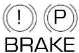

Driving a vehicle with the brake system warning light on is dangerous. A significant decrease in braking performance may
occur. It will take you longer to stop the vehicle. Have the vehicle checked by your authorized dealer. Driving extended distances with the parking brake engaged can cause brake failure and the risk of personal injury.
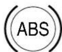
Anti-lockbrakesystem: If the
ABS light stays illuminated or continues to flash, a malfunction has
been detected, have the system serviced immediately by your
authorized dealer. Normal braking is still functional unless the brake warning light also is illuminated.
Instrument Cluster
Airbagreadiness: If this light fails to illuminate when ignition is turned to the RUN position, continues to flash or remains on, have the system
serviced immediately by your authorized dealer. A chime will also sound when a malfunction in the supplemental restraint system has been detected.

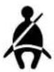
Safetybelt: Reminds you to fasten your safety belt. A Belt-Minder® chime will also sound to remind you to fasten your safety belt. Refer to the Seatingandsafetyrestraints chapter to activate/deactivate the Be
Mastervehicleelectricalhazard warninglamp: Indicates Hybrid component fault/failure that will cause the vehicle to shutdown or fail to start.

Note: If the vehicle is still running, the vehicle may soon shutdown without further warning and should be stopped safely.
If this lamp is lit, stop the vehicle, shift to P (Park), turn the key to the Off position, and attempt to restart the vehicle. If the fault remains, the vehicle may require refueling, jump starting, resetting of the shut-off switches, or service. For information regarding Lowvoltage [underhood]batteryonly)and Fuelpump/Highvoltageshut-off switchesplease refer to the RoadsideEmergencieschapter.
Readyindicatorlight: Illuminates once the vehicle has successfully started. Indicates the vehicle is ready to drive even when you don't hear the engine running.

Charging system: Illuminates when the 12V charging system is not working properly.

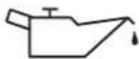
Engineoilpressure:Illuminates when the oil pressure falls below the normal range, refer to Engineoil in the Maintenance and Specificationschapter.
Instrument Cluster
Engineormotorelectronic
coolanttemperature:Illuminates when the coolant temperature exceeds the threshold. When the light is flashing or remains on, stop the vehicle as soon as possible, switch off the engine and let cool. Refer to Enginecoolantandmotor/electronicscoolantin the Maintenance andSpecificationschapter.


Never remove the coolant reservoir cap while the engine is running or hot.
ABSactive/Tractioncontrol® active(ifequipped):Flashes
when the ABS system is active. If the light remains on, have the system serviced immediately, refer to the Drivingchapter for more information.
Lowtirepressurewarning:
Illuminates when your tire pressure is low. If the light remains ON at start up or while driving, the tire pressure should be checked. Refer to Inspecting and Inflating Your Tires in the Tires, Wheels and Loadingchapter. When the ignition is first turned to RUN, the light will illuminate for 3 seconds to ensure the bulb is working. If the light does not turn ON or begins to flash, have the system inspected by your authorized dealer. For more information on this system, refer to UnderstandingYourTirePressureMonitoringSystemin the Tires, WheelsandLoadingchapter.
Lowfuel: Illuminates when the fuel level in the fuel tank is at or near empty (refer to Fuelgauge in this chapter).

Instrument Cluster
Speedcontrol: Illuminates when the speed control is engaged. Turns off when the speed control system is disengaged.
Anti-theftsystem: Flashes when the SecuriLock ™ Passive Anti-theft System has been activated.
Throttlecontrol/Powertrain:
Illuminates when a powertrain fault has been detected. Contact your authorized dealer as soon as possible.
Doorajar: Illuminates when the ignition is in the RUN position and any door is open.
Turnsignal: Illuminates when the left or right turn signal or the hazard lights are turned on. If the indicators flash faster, check for a burned out bulb.
Highbeams: Illuminates when the high beam headlamps are turned on.






Key-in-ignitionwarningchime: Sounds when the key is left in the ignition in the OFF/LOCK or ACCESSORY position and the driver's door is opened.
Headlampsonwarningchime: Sounds when the headlamps or parking lamps are on, the ignition is off (the key is not in the ignition) and the driver's door is opened.
ParkingbrakeONchime: Sounds when the parking brake is left ON and the vehicle is driven. If the warning stays on after the park brake is off, contact your authorized dealer as soon as possible.
Transmissionnotinparkchime: Sounds when the PRNDL is not in P (Park) position, the driver's door is ajar and the ignition is in RUN.
HEVEngineoffReminderChime: Sounds for 10 seconds when the PRNDL is in the P (Park) position and the Driver's door is ajar (open)
Instrument Cluster
while ignition is in RUN. Always turn your ignition key to Off and remove key before leaving your vehicle. (The engine may be off when the vehicle is stopped, yet the key is on, and the engine can turn on at any time)
Messagecenteractivationchime: Sounds when a warning message (except PARKING BRAKE ENGAGED while parked) appears in the message center display for the first time.
GAUGES

Speedometer: Indicates the current vehicle speed.

Batterygauge: Provides information about the vehicle's energy usage.
• ASSIST — Battery provides extra power to boost the vehicle's acceleration.
- CHARGE — Storing extra energy in the battery when coasting or slowing down.

Instrument Cluster
Odometer: Registers the total miles (kilometers) of the vehicle.
Refer to MessageCenter in the DriverControls chapter on how to switch the display from Metric to English.
Tripodometer: Registers the miles (kilometers) of individual journeys. To reset, press and release the message center INFO button until TRIP A mode appears in the display. Press the control again to select the TRIP B feature. Press and hold the RESET button to reset.
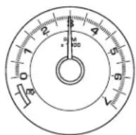
Tachometer: Indicates the engine speed in revolutions per minute. Driving with your tachometer pointer continuously at the top of the scale (in the red zone) may damage the engine. The pointer will indicate engine RPMs when the engine is running and point at the EV symbol when the engine is off and the vehicle is running on pure electrical power.
Fuelgauge:Indicates approximately how much fuel is left in the fuel tank (when the ignition is in the ON position). The fuel gauge may vary slightly when the vehicle is in motion or on a grade.
Refer to Fillingthetankin the Maintenance and Specifications chapter for more information.
0.0 mi
TRIP A XXX.X mi 0.0 mi
Entertainment Systems
AUDIO SYSTEMS
AM/FM/single CD/in-dash CD6/MP3 satellite compatible sound system
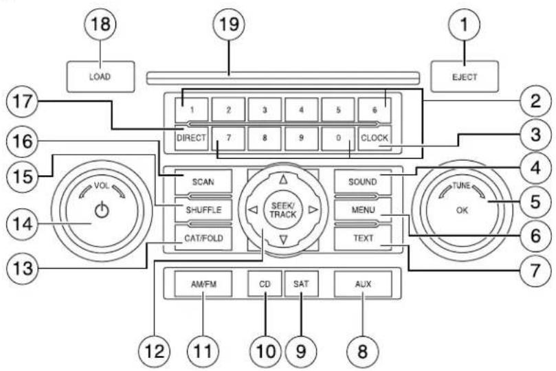
Accessorydelay: Your vehicle is equipped with accessory delay. With this feature, the window switches, radio and moon roof (if equipped) may be used for up to ten minutes after the ignition is turned off or until either front door is opened.
Note: Your vehicle is equipped with a unique audio system. If your display shows six small circles in the display, your audio system is a CD6 system. If not, your system is a Single CD system.

1. EJECT:ForasingleCD
system, press EJECT to eject the CD.

ForaCD6system, press ELECT and select the desired CD slot by pressing the corresponding memory preset #. The display will read EJECTING #. When the system has ejected the CD, the display will read
Entertainment Systems
REMOVE CD #. Remove the CD. If you do not remove the CD the system will reload the disc.
Toautoejectallloadeddiscs, press and hold EJECT. The system will eject all discs and prompt you when to remove them.
2. MEMORYPRESETS:Inradio
mode, to set a station, select the desired frequency band, AM, FM1 or FM2. Tune to the desired station. Press and hold a preset button until sound returns and PRESET # SAVED appears in the display. You can save up to 30 stations, 10 in AM, 10 in FM1 and FM2.
InCD/MP3mode, press to select tracks or desired folders.

Insatelliteradiomode(ifequipped), there are 30 available presets, 10 each for SAT1, SAT2 and SAT3. To save satellite channels in your memory presets, tune to the desired channel then press and hold a preset control until sound returns.
SatelliteradioisavailableonlywithavalidSIRIUSradio subscription. Checkwithyourauthorizeddealerforavailability.
3. CLOCK: To set the time, press
CLOCK. The display will read SET TIME. Use the memory preset #s to enter in the desired time, hours and minutes. The clock will then begin from that time.
4. SOUND: Press repeatedly to
cycle through the following features:


BASS: Press SOUND repeatedly to reach the bass setting. Press
◀ SEEK/TRACK ▶ adjust the level of bass.
TREBLE:Press SOUND repeatedly to reach the treble setting. Press
SEEK/TRACK ▶ adjust the level of treble.
BALANCE: Press SOUND repeatedly to reach the balance setting.
Press ◀ SEEK/TRACK ▶ adjust the audio between the left (L) and right (R) speakers.
FADE:Press SOUND repeatedly to reach the bass setting. Press
◀ SEEK/TRACK ▶ adjust the audio between the back (B) and front (F) speakers.
SPEEDCOMPENSATEDVOLUME(ifequipped):Press SOUND
repeatedly to reach the SPEED COMPENSATED VOLUME setting. Radio
Entertainment Systems
volume automatically gets louder with increasing vehicle speed to
compensate for road and wind noise. Use ← SEEK/TRACK to adjust.
The default setting is off; increasing your vehicle speed will not change the volume level.
Adjust 1–7: Increasing this setting from 1 (lowest setting) to 7 (highest setting) allows the radio volume to automatically change slightly with vehicle speed to compensate for road and wind noise.
Recommended level is 1–3;SPEED OFF turns the feature off and level 7 is the maximum setting.
ALLSEATS(Occupancymode, ifequipped): Press SOUND
repeatedly to reach the Occupancy mode setting. Press
SEEK/TRACK to select and optimize sound for ALL SEATS,
DRIVERS SEAT or REAR SEATS.
- TUNE: Inradiomode, turn right / left to go up / down the frequency band in individual increments.
Insatelliteradiomode
(ifequipped), turn right / left to go to the next / previous available SIRIUS satellite station.
- MENU: Press repeatedly to access the following features:
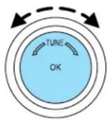

AUTOPRESETON/OFF:Press ◀ SEEK/TRACK to toggle
between ON/OFF. Autoset allows you to set the strongest local radio stations without losing your original manually set preset stations for AM/FM1/FM2. To activate the autoset feature, toggle AUTOSET to ON, and either wait five seconds for the search to initiate or press OK to immediately initiate the search. (If you press another control within those five seconds, the search will not initiate.) The 10 strongest stations will be filled and the station stored in preset 1 will begin playing. If there are less than 10 strong stations, the system will store the last one in the remaining presets.
RDSON/OFF: Available only in FM mode. This feature allows you to search RDS-equipped stations for a certain category of music format: CLASSIC, COUNTRY, JAZZ/RB, ROCK, etc.
Entertainment Systems
Toactivate, press MENU repeatedly until RDS (ON/OFF) appears in the display. Use ◀ SEEK/TRACK ▶ toggle RDS ON/OFF. When RDS is OFF, you will not be able to search for RDS equipped stations or view the station name or type.
Tochangecategories: Press MENU until RDS ON appears in the display. Press CAT. Press ▲ / ▼ until the desired category appears in the display. Then press SEEK/TRACK to find the next station playing that category of music or SCAN for a brief sampling of all stations playing that category of music.
COMPRESSION: Available only in CD/MP3 mode. Press MENU until COMPRESSION ON/OFF appears in the display. Use
SEEK/TRACK to toggle ON/OFF. When COMPRESSION is ON, the system will bring the soft and loud CD passages together for a more consistent listening level.
- TEXT: InMP3mode, press
TEXT repeatedly to view Album
(AL), Folder (FL), Song (SO) and
Artist (AR) in the display, if available.

Insatelliteradiomode(ifequipped), press and release to display the artist and song title. While in TEXT MODE, press again to scroll through the Artist (AR), Song (SO), Channel (CH) and Category (CA).
InTEXTMODE, sometimes the display requires additional text to be displayed. When the </ /> indicator is active, press TEXT and then press ◀ SEEK/TRACK ▶ view the additional display text.
- AUX: Press AUX to access LINE (auxiliary audio mode).
For location and further information on auxiliary audio mode, refer to Auxiliaryinputjacklater in this chapter.

-
SAT(SatelliteRadio, if equipped): Press SAT to access satellite radio mode, if equipped. Press repeatedly to cycle through SAT1, SAT2 and SAT3 modes.
-
CD:Press to enter CD/MP3
mode. If a disc is already loaded
into the system, CD/MP3 play will
begin where it ended last. If no CD is loaded, NO DISC will appear in the display.

Entertainment Systems
- AM/FM: Press repeatedly to select AM/FM1/FM2 frequency band.

- SEEK/TRACK:Inradiomode,
press ◀ SEEK/TRACK ▶ access the previous/next strong radio station.
InCD/MP3mode, press ◀ SEEK/TRACK ▶ access the previous/next track.

Insatelliteradiomode(ifequipped),press
SEEK/TRACK
seek to the previous/next channel. If a specific category is selected, (Jazz, Rock, News, etc.), press ◀ SEEK/TRACK ▶ seek to the previous/next channel in the selected category. Press and hold ◀ SEEK/TRACK ▶ fast seek through the previous/next channels.
InCategorymode, press SEEK/TRACK to select a category. SatelliteradioisavailableonlywithavalidSIRIUSsubscription. Checkwithyourauthorizeddealerforavailability.
- CAT(Category)/FOLD

(Folder):
InCategorymode, use to select from various music categories. To change RDS categories, ensure that RDS is ON in the Menu listing. Press MENU again until RDS ON appears in the display. Press CAT. PRESS UP OR DOWN TO CHANGE RDS CATEGORY will appear in the display. Press ▲ SEEK/TRACK ▼ scroll through all possible categories. When the desired category appears in the display, press ◀ SEEK/TRACK ▶ find the next station playing that selection or press SCAN for a brief sampling of all stations playing that category of music.
InMP3mode, press FOLD and then press previous/next folder.
◀ /to access the
Insatelliteradiomode(ifequipped), use to select from various satellite radio categories. To change categories in satellite radio mode, press CAT/FOLD. The active category will appear in the display. Press ▲ SEEK/TRACK ▼ turn the TUNE knob left/right to scroll through the available categories. Press and hold SCAN for a brief sampling of all channels in that category or press SEEK to seek to the next channel in that category.
Entertainment Systems
- ON/OFF/VOL(Volume):Press to turn ON/OFF. Turn to increase/decrease volume.
Note: If the volume is set above a certain level and the ignition is turned off, the volume will come back on at a "nominal" listening level when the ignition switch is turned back on.

15. SHUFFLE:
InCDandMP3mode, press
SHUFFLE to engage shuffle mode. SHUFFLE ON will appear in the display. If you wish to engage shuffle mode right away, press ◀ SEEK/TRACK ▶ begin random play. Otherwise, random play will begin when the current track is finished playing. SHUFFLE and the track # will appear in the display. To disengage, press SHUFFLE again. SHUFFLE OFF will appear in the display.

ForasingleCDsystem, the system will shuffle within the current disc.
ForaCDX6system, the system will shuffle between all loaded discs. The disc # will appear in the top left hand corner of the display.
- SCAN:Inradiomode, press for a brief sampling of all strong radio stations.

InCD/MP3mode, press for a brief sampling of all tracks on the current disc or folder.
Insatelliteradiomode(ifequipped),press SCAN for a brief sampling of all available SIRIUS satellite channels. If a specific category is selected, (Jazz, Rock, News, etc.) press SCAN for a brief sampling of all available SIRIUS satellite channels within the selected Category.
- DIRECT: Press to access a desired radio station, track, MP3 folder or SIRIUS satellite channel (if equipped).

Inradiomode, press DIRECT and then press the desired radio frequency (i.e. 101.1) using the memory presets.
InCDmode, press DIRECT. The display will read DIRECT TRACK MODE SELECT TRACK. Enter the desired track number using the numbered controls. The system will then begin playing that track.
Entertainment Systems
InMP3foldermode, press DIRECT and the number of the desired folder. The system will advance to that specific folder.
Insatelliteradiomode(ifequipped),press DIRECT then enter the desired channel (i.e. 002) using the memory presets. If you only enter one digit, press OK and the system will go to that satellite channel. If you enter three digits, the system will automatically go to that channel, if available. You may cancel your entry by pressing DIRECT. If an invalid station number is entered, INVALID CHANNEL will appear in the display and the system will continue playing the current station.
18. LOAD:ForasingleCD
system, this control is not
operational. To load a CD, simply
insert the disc label side up into the CD slot.
ForaCD6system, press LOAD. When the display reads SELECT
SLOT, choose the desired slot number using memory presets 1–6. When the display reads LOAD CD#, load the desired disc, label side up. If you do not choose a slot within 5 seconds, the system will choose for you. Once loaded, the first track will begin to play.
Toautoloadupto6discs, press and hold LOAD until the display reads AUTOLOAD#. Load the desired disc, label side up. The system will prompt you to load discs for the remaining available slots. Insert the discs, one at a time, label side up, when prompted. Once loaded, the disc in preset #1 will begin to play.
19. CDslot:ForasingleCD
system, insert a CD/MP3, label side up.
ForaCD6system, press LOAD and select a CD slot using the memory presets. When prompted by the system, insert a CD/MP3 label side up.
LOAD

Entertainment Systems
Auxiliary input jack
Your vehicle is equipped with an Auxiliary Input Jack (AIJ). The Auxiliary Input Jack provides a way to connect your portable music player to the in-vehicle audio system. This allows the audio from a portable music player to be played through the vehicle speakers with high fidelity. To achieve optimal performance, please observe the following instructions when attaching your portable music device to the audio system.

Requiredequipment:
- Any portable music player designed to be used with headphones
- An audio extension cable with stereo male 1/8 in. (3.5 mm) connectors at each end
Toplayyourportablemusicplayerusingtheauxiliaryinputjack:
- Begin with the vehicle parked and the radio turned off.
- Ensure that the battery in your portable music player is new or fully charged and that the device is turned off.
- Attach one end of the audio extension cable to the headphone output of your player and the other end of the audio extension cable to the AIJ in your vehicle.
- Turn the radio on, using either a tuned FM station or a CD loaded into the system. Adjust the volume to a comfortable listening level.
- Turn the portable music player on and adjust the volume to 1/2 the volume.
Entertainment Systems
- Press AUX on the vehicle radio repeatedly until LINE IN appears in the display. You should hear audio from your portable music player although it may be low.
- Adjust the sound on your portable music player until it reaches the level of the FM station or CD by switching back and forth between the AUX and FM or CD controls.
Troubleshooting:
- Do not connect the audio input jack to a line level output. Line level outputs are intended for connection to a home stereo and are not compatible with the AIJ. The AIJ will only work correctly with devices that have a headphone output with a volume control.
- Do not set the portable music player's volume level higher than is necessary to match the volume of the CD or FM radio in your audio system as this will cause distortion and will reduce sound quality. Many portable music players have different output levels, so not all players should be set at the same levels. Some players will sound best at full volume and others will need to be set at a lower volume.
- If the music sounds distorted at lower listening levels, turn the portable music player volume down. If the problems persist, replace or recharge the batteries in the portable music player.
- The portable music player must be controlled in the same way manner when it is used with headphones as the AIJ does not provide control (play, pause, etc.) over the attached portable music player.
- For safety reasons, connecting or adjusting the settings on your portable music player should not be attempted while the vehicle is moving. Also, the portable music player should be stored in a secure location, such as the center console or the glove box, when the vehicle is in motion. The audio extension cable must be long enough to allow the portable music player to be safely stored while the vehicle is in motion.
GENERAL AUDIO INFORMATION
Radiofrequencies:
AM and FM frequencies are established by the Federal Communications Commission (FCC) and the Canadian Radio and Telecommunications Commission (CRTC). Those frequencies are:
AM: 530, 540–1700, 1710 kHz
FM: 87.7, 87.9–107.7, 107.9 MHz
Entertainment Systems
Radioreceptionfactors:
There are three factors that can affect radio reception:
- Distance/strength: The further you travel from an FM station, the weaker the signal and the weaker the reception.
- Terrain: Hills, mountains, tall buildings, power lines, electric fences, traffic lights and thunderstorms can interfere with your reception.
- Station overload: When you pass a broadcast tower, a stronger signal may overtake a weaker one and play while the weak station frequency is displayed.
CD/CDplayercare
Do:
- Handle discs by their edges only. (Never touch the playing surface).
- Inspect discs before playing.
- Clean only with an approved CD cleaner.
• Wipe discs from the center out.


Don't:
- Expose discs to direct sunlight or heat sources for extended periods of time.
- Clean using a circular motion.
CDunitsaredesignedtoplaycommerciallypressed4.75in (12cm)audiocompactdiscsonly.Duetotechnical incompatibility,certainrecordableandre-recordablecompact discsmaynotfunctioncorrectlywhenusedinFordCDplayers.
Entertainment Systems
Donotuseanyirregularshaped CDsordiscswithascratch protectionfilmattached.

CDswithhomemadepaper (adhesive)labelsshouldnotbe insertedintotheCDplayeras thelabelmaypeelandcausethe CDtobecomejammed.Itis recommendedthathomemade CDsbeidentifiedwith permanentfelttipmarkerrather thanadhesivelabels.BallpointpensmaydamageCDs.Please contactyourauthorizeddealerforfurtherinformation.

Audiosystemwarrantyandservice
Refer to the WarrantyGuide for audio system warranty information. If service is necessary, see your dealer or qualified technician.
Satellite radio information (if equipped)
Satelliteradiochannels:SIRIUS broadcasts a variety of music, news, sports, weather, traffic and entertainment satellite radio channels. For more information and a complete list of SIRIUS satellite radio channels, visit www.sirius.com in the United States, www.sirius-canada.ca in Canada, or call SIRIUS at 1-888-539-7474.
Satelliteradioreceptionfactors: To receive the satellite signal, your vehicle has been equipped with a satellite radio antenna located on the roof of your vehicle. The vehicle roof provides the best location for an unobstructed, open view of the sky, a requirement of a satellite radio system. Like AM/FM, there are several factors that can affect satellite radio reception performance:
- Antenna obstructions: For optimal reception performance, keep the antenna clear of snow and ice build-up and keep luggage and other material as far away from the antenna as possible.
- Terrain: Hills, mountains, tall buildings, bridges, tunnels, freeway overpasses, parking garages, dense tree foliage and thunderstorms can interfere with your reception.
Entertainment Systems
- Station overload: When you pass a ground based broadcast repeating tower, a stronger signal may overtake a weaker one and result in an audio mute.
Unlike AM/FM audible static, you will hear an audio mute when there is a satellite radio signal interference. Your radio display may display NO SIGNAL to indicate the interference.
SIRIUSsatelliteradioservice:SIRIUS Satellite Radio is a subscription based satellite radio service that broadcasts music, sports, news and entertainment programming. A service fee is required in order to receive SIRIUS service. Vehicles that are equipped with a factory installed SIRIUS Satellite Radio system include:
- Hardware and limited subscription term, which begins on the date of sale or lease of the vehicle.
- Online media player providing access to all 65 SIRIUS music channels over the internet (U.S. customers only).
For information on extended subscription terms, contact SIRIUS at 1-888-539-7474.
Note: SIRIUS reserves the unrestricted right to change, rearrange, add or delete programming including canceling, moving or adding particular channels, and its prices, at any time, with or without notice to you. Ford Motor Company shall not be responsible for any such programming changes.
SatelliteRadioElectronicSerialNumber(ESN):This 12-digit Satellite Serial Number is needed to activate, modify or track your satellite radio account. You will need this number when communicating with SIRIUS. While in Satellite Radio mode, you can view this number on the radio display by pressing AUX and Preset 1 control simultaneously.
Entertainment Systems
| RadioDisplayConditionActionRequired | ||
| ACQUIRING Radio requires more than two seconds to produce audio for the selected channel. | No action required.This message should disappear shortly. | |
| SAT FAULT Internal module or system failure present. | If this message does not clear within a short period of time, or with an ignition key cycle,your receiver may have a fault. See your authorized dealer for service. | |
| INVALID CHNL Channel no longer available. | This previously available channel is no longer available. Tunc to another channel. If the channel was one of your presets, you may choose another channel for that preset button. | |
| UNSUBSCRIBED Subscription not available for this channel. | Contact SIRIUS at 1-888-539-7474 to subscribe to the channel or tune to another channel. | |
| NO TEXT Artist information not available. | Artist information not available at this time on this channel. The system is working properly. | |
Entertainment Systems
| RadioDisplayConditionActionRequired | ||
| NO TEXT Song title information not available. | Song title information not available at this time on this channel. The system is working properly. | |
| NO TEXT Category information not available. | Category information not available at this time on this channel. The system is working properly. | |
| NO SIGNAL Loss of signal from the SIRIUS satellite or SIRIUS tower to the vehicle antenna. | You are in a location that is blocking the SIRIUS signal (i.e., tunnel, under an overpass, dense foliage, etc). The system is working properly. When you move into an open area, the signal should return. | |
| UPDATING Update of channel programming in progress. | No action required. The process may take up to three minutes. | |
| CALL SIRIUS 1-888-539-7474 | Satellite service has been deactivated by SIRIUS Satellite Radio. | Call SIRIUS at 1-888-539-7474 to re-activate or resolve subscription issues. |
NAVIGATION SYSTEM (IF EQUIPPED)
Your vehicle may be equipped with a Navigation System. Refer to the Navigationsupplement for further information.
DUAL AUTOMATIC TEMPERATURE CONTROL

- AUTO/Drivertemperature: Press to engage full automatic operation. The system will automatically determine fan speed, airflow distribution, A/C on or off, and outside or recirculated air, to heat or cool the vehicle to reach the desired temperature. Turn to increase/decrease the temperature on the driver side of the vehicle. The control also adjusts the passenger side temperature when PASS TEMP is disengaged. The recommended initial setting is between 72°F (22°C) and 75°F (24°C), then adjust for comfort. The driver side temperature setting will appear in the upper left corner of the display. The engine may run continuously to provide A/C operation unless ECON mode is selected. Selecting ECON mode affects A/C operation. Refer to ECON information later in this section.
- Reardefroster: Press to activate/deactivate the rear window defroster. Refer to Rearwindowdefrosterlater in this chapter for more information.
- Defrost: Distributes outside air through the windshield defroster vents and demister vents. Can be used to clear the windshield of fog and thin ice. The system will automatically provide outside air to reduce window fogging. On days where the outside temperature is approximately freezing or higher, the engine will run continuously in this mode. Press this button again to return to the previous air flow selection or press AUTO to return to automatic operation.
- Defrost/Floor: Distributes air through the windshield defroster vents, demister vents, floor vents and rear seat floor vents. The system
Climate Controls
will automatically provide outside air to reduce window fogging. On days where the outside temperature is approximately freezing or higher, the engine will run continuously in this mode.
- Power/press to activate/deactivate the climate control system. When the system is off, outside air is shut out. Turn to manually increase/decrease the fan speed. The manual fan speed setting will appear on the left side of the display. To return to automatic fan operation, press AUTO.
- 🚗 Panel: Distributes air through the instrument panel vents.
- Panel/Floor: Distributes air through the instrument panel vents, demister vents, floor vents and rear seat floor vents.
- √ Floor: Distributes air through the demister vents, floor vents and rear seat floor vents.
- Passengertemperature: Press to engage/disengage separate passenger side temperature control. Turn to increase/decrease the temperature on the passenger side of the vehicle. The recommended initial setting is between 72°F (22°C) and 75°F (24°C), then adjust for comfort. The passenger side temperature setting will appear in the upper right corner of the display.
- Passengerheatedseatcontrol(ifequipped):Press to activate/deactivate the passenger heated seat. See Heatedseatsin the SeatingandSafetyRestraintschapter.
- Recirculatedair:Press to activate/deactivate air recirculation in the vehicle. Recirculated air may reduce the amount of time needed to cool down the interior of the vehicle, may reduce the energy needed to keep the interior of the vehicle cool, and may also help reduce undesired outside odors from reaching the interior of the vehicle. Recirculated air is controlled automatically when AUTO is selected or can be engaged manually in any airflow mode except (defrost). Recirculated air may turn off automatically in some airflow modes to reduce window fogging potential. When the ignition switch is turned off and back on, the climate system will return to the recirculated air mode only if the A/C button LED is illuminated and the air distribution selection is either AUTO, (panel) or (panel/floor).
- ECON: Press to activate/deactivate economy air conditioning operation. ECON mode may provide improved fuel economy by preventing the gasoline engine from running for the sole purpose of providing A/C. When the gas engine turns off, the A/C compressor does
Climate Controls
not operate to cool the cabin and comfort may be reduced. In ECON mode, A/C operates as normal when the gasoline engine is running. To prioritize cooling comfort over fuel economy, deactivate ECON. ECON can not be selected in (defrost) or (floor/defrost).
- A/C: Press to activate/deactivate air conditioning. Use with recirculated air to improve cooling performance and efficiency. Engages automatically in AUTO, (defrost) and (for/defrost). Selecting ECON mode affects A/C operation. Refer to ECON information previously in this section.
- 🚗 Driverheatedseatcontrol(ifequipped):Press to activate/adjective the driver heated seat. See Heatedseatsin the SeatingandSafetyRestraintschapter.
Outsidetemperature:The outside temperature will appear in the display and is labeled EXT TEMP.
Temperatureconversion: To switch between Fahrenheit and Celsius, refer to Setup menu in the Message center section of the Driver Controlschapter.
Operating tips
- To reduce fog build up on the windshield during humid weather, select (defrost) or (floor/defrost).
- To reduce humidity build up inside the vehicle, do not drive with the system OFF or with (recirculated air) engaged and A/C off.
- Do not put objects under the front seats that will interfere with the airflow to the back seats by blocking the air from the rear seat floor vents.
- Remove any snow, ice or leaves from the air intake area at the base of the windshield.
- To improve the A/C cool down, drive with the windows slightly open for 2-3 minutes after start up or until the vehicle has been “aired out.”
Formaximumcoolingperformance:
•Automaticoperation:
- Press AUTO for full automatic operation.
- Do not override A/C or (recirculated air).
- Set the temperature to 60° F ( 16° C).
Make sure ECON mode is deactivated.
Climate Controls
- Manualoperation:
- Select A/C.
- Select ↗ or ↗
- Select (recirculated air) to provide colder airflow.
- Set the temperature to 60° F ( 16° C).
- Set highest fan setting initially, then adjust to maintain comfort.
Make sure ECON mode is deactivated.
Toaidinsidewindowdefogging/demistingincoldweather:
- Select ↗ .
- Select A/C.
- Adjust the temperature control to maintain comfort.
- Set the fan speed to the highest setting.
- Direct the outer instrument panel vents towards the side windows.
To increase airflow to the outer instrument panel vents, close the vents located in the middle of the instrument panel.

Do not place objects on top of the instrument panel as these objects may become projectiles in a collision or sudden stop.
REAR WINDOW DEFROSTER R
The rear defroster control is located on the climate control panel and works to clear the rear window of fog and thin ice.
The ignition must be in the 3 (RUN) position to operate the rear window defroster.
Press R to turn the rear window defroster on. An indicator light on the button will illuminate when active. The rear window defroster turns off automatically after approximately 15 minutes. If a low battery condition is detected or the ignition is turned to the 1 (LOCK) or 2 (ACC) position, the rear window defroster will not function. To manually turn off the rear window defroster at any time, press R again.
If your vehicle is equipped with both rear defroster and heated mirrors, the same button will activate both. Refer to Heatedoutsidemirrors in the DriverControlschapter.
Donotuserazorbladesorothersharpobjectstocleantheinside oftherearwindowortoremovedecalsfromtheinsideorthe rearwindow. This may caused damage to the heated gridlines and will not be recovered by your warranty.
HEADLAMP CONTROL
Rotate the headlamp control to the first position P≤ to turn on the parking lamps. Rotate to the second position ≡D to turn on the headlamps.

Autolamp control (if equipped)

The autolamp system provides light sensitive automatic on-off control of the exterior lights normally controlled by the headlamp control.
The autolamp system is factory programmed to keep the lights on for 20 seconds after the ignition switch is turned to off. This delay can be programmed, using the procedure listed below, to any value up to 180 seconds. If equipped, this delay can also be programmed through
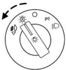
- To turn autolamps on, rotate the control counterclockwise.
- To turn autolamps off, rotate the control clockwise to OFF.
Note: If the vehicle is equipped with autolamps it will have the headlampsonwithwindshieldwipersfeature. If the windshield wipers are turned on (for a fixed period of time) the exterior lamps will turn on with headlamp control in the Autolamp position.
Lights
Autolampdelaysystem(ifequipped)
If your vehicle is equipped with autolamps, you can set the delay time to keep the headlights on for up to three minutes after the key is turned OFF. The delay time is set to 20 seconds at the factory, but the delay time may be changed by following the steps below (Steps 1 through 6 must be done within 10 seconds):
-
Turn the key to the 1 (LOCK) position.
-
Rotate the headlamp control to the autolamp position.
-
Rotate the headlamp control to the OFF position.
-
Turn the key to the 3 (RUN) position.
-
Turn the key back to the 1 (LOCK) position.
-
Turn the headlamp control to the autolamp position (the headlights should turn on).
-
Turn the headlamp control to the OFF position when the desired delay time (up to 3 minutes) has been reached.
![graph TD A["1"] --> B["2"] B --> C["3"] C --> D["4"]](/content/2026/05/1033069/images/8acb7ef6146611a964e471c2536f9c8e6f115828687d2eb746ad6b3c7cbf9d0b.jpg)
Foglamp control (if equipped) ≠0
The headlamp control also operates the foglamps. The foglamps can be turned on when the headlamp control is in the P≤, ☐ or ☐D positions and the high beams are not turned on.
Pull headlamp control towards you to turn foglamps on. The foglamp indicator light #0 will illuminate.

Lights
High beams ≡D
Push the lever toward the instrument panel to activate. Pull the lever towards you to deactivate.

Flash to pass
Pull toward you slightly to activate and release to deactivate.
Daytime running lamps (DRL) (if equipped)
Turns the lowbeam headlamps on with a reduced output.
To activate:
• the ignition must be in the 3 (RUN) position.
- the headlamp control must be in the OFF, parking lamps or autolamp position.
• the transmission is not in P (Park),

Always remember to turn on your headlamps at dusk or during inclement weather. The Daytime Running Lamp (DRL) system not activate the tail lamps and generally may not provide adequate lighting during these conditions. Failure to activate your lamps under these conditions may result in a collision.
Lights
PANEL DIMMER CONTROL
Use to adjust the brightness of the instrument panel and all applicable switches in the vehicle during headlamp and parklamp operation.
Move the control to the full upright position, past detent, to turn on the interior lamps.
Rotate to full down position (past detent) to prevent interior lamps from illuminating when the doors are opened.

AIMING THE HEADLAMPS
The headlamps on your vehicle are properly aimed at the assembly plant. If your vehicle has been in an accident the alignment of your headlamps should be checked by your authorized dealer.
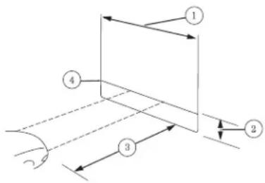
Vertical aim adjustment
- Park the vehicle directly in front of a wall or screen on a level surface, approximately 25 feet (7.6 meters) away.
•(1) 8 feet (2.4 meters)
• (2) Center height of lamp to ground
• (3) 25 feet (7.6 meters)
•(4) Horizontal reference line
- Measure the height from the center of your headlamp to the ground and mark an 8 foot
(2.4 meter) horizontal reference line on the vertical wall or screen at this height (a piece of masking tape work marked by a 3.0 mm circle on the head
- Turn on the low beam headlamps to illuminate the wall or screen and open the hood. Cover the left-hand headlamp with an opaque cloth.
Lights
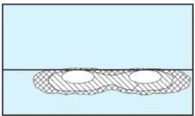
- On the wall or screen you will observe a light pattern with a distinct horizontal edge of high intensity light towards the right. If this edge is not at the horizontal reference line, the beam will need to be adjusted.
-
Locate the vertical adjuster on the headlamp, then usca4mm socket to turn the adjuster either counterclockwise (to adjust up) or clockwise (to adjust down) aligning the upper edge of the light pattern to the horizontal line.
-
Move the opaque cloth to cover the right-hand headlamp and repeat Steps 4 and 5 for the left-hand headlamp.

-
HORIZONTAL AIM IS NOT REQUIRED FOR THIS VEHICLE AND IS NON-ADJUSTABLE.
-
Close the hood and turn off the lamps.
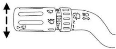
TURN SIGNAL CONTROL ⇔
- Push down to activate the left turn signal.
- Push up to activate the right turn signal.
INTERIOR LAMPS
Dome lamps and map lamps
The front dome lamp is located overhead between the driver and passenger seats.
Lights
The dome lamp control has three positions:
• OFF: In this position, the lamp will not illuminate.
- DOOR: In this position, the dome lamp will illuminate only when a door is opened and will remain illuminated for 25 seconds after the door is shut.
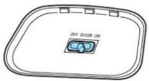
- ON: In this position, the lamp will remain illuminated.
The map lamp controls (without moon roof) are located on the dome lamp. Press the button on either side of each map lamp to illuminate the lamps. Push the button again to turn off the lamps.
For models equipped with a moon roof, the map lamps are located on the moon roof control panel. Press the button on either side of each map lamp to illuminate the lamps. Push the button again to turn off the lamps.

The map lamps will illuminate whenever a door is opened. After the door is shut, the lamps will remain illuminated for 25 seconds.
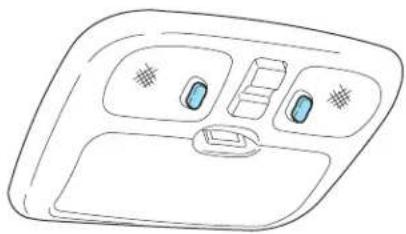
Cargo and dome lamp
Rear cargo lamp equipped with an ON/OFF/DOOR control will light when:
• the doors are closed and the control is in the ON position.
• the control is in the DOOR position and any door is open.

When the control is in the OFF position, it will not illuminate when you open the doors.
Interiorlightingbatterysaver
The interior lamps will automatically extinguish after 10 minutes when the ignition key is in OFF/LOCK position, a door has been left open or the interior lamp controls are in the ON position.
BULB REPLACEMENT
Headlamp Condensation
The headlamps are vented to equalize pressure. When moist air enters the headlamp(s) through the vents, there is a possibility that condensation can occur. This condensation is normal and will clear within 45 minutes of headlamp operation.
Using the right bulbs
Replacement bulbs are specified in the chart below. Headlamp bulbs must be marked with an authorized “D.O.T.” for North America and an “E” for Europe to ensure lamp performance, light brightness and pattern and safe visibility. The correct bulbs will not damage the lamp assembly or void the lamp assembly warranty and will provide quality bulb burn time.
| FunctionNumberofbul | IbsTradenumber | |
| Headlamps (high and low beams) | 2 | H13 |
| Park/turn lamps (front) | 2 | 3457 NAK (amber) |
| Side marker (front) 2 194 | ||
| Rear stop/tail/sidemarker | 2 | 4157K |
| Backup lamp 2 921 | ||
| Foglamp (front) 2 PS24WFF | ||
| Center High-mount stop lamp | 5 | W5WL |
| Rear license plate lamp | 2 | 168 |
| All replacement bulbs are clear in color except where noted. | ||
| To replace all instrument panel lights - see your authorized dealer | ||
Lights
Replacing the interior bulbs
Check the operation of all bulbs frequently.
Replacing exterior bulbs
Check the operation of all the bulbs frequently.
Replacingheadlampbulbs
- Make sure that the headlamp control is in the OFF position.
- Open the hood.
- Reach over the front bolster.
- Remove the bulb by turning it counterclockwise and then pulling it straight out.
- Disconnect the electrical connector from the bulb.
Handle a halogen headlamp bulb carefully and keep out of children's reach. Grasp the bulb only by its plastic base and do not touch the glass. The oil from your hand could cause the bulb to break the next time the headlamps are operated.


- Connect the electrical connector on the new bulb.
- Insert the glass end of the new bulb into the headlamp assembly. When the grooves in the plastic base are aligned, turn the new bulb clockwise to install.
Lights
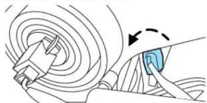
Replacingfrontparkinglamp/turnsignalbulbs
-
Make sure that the headlamp control is in the OFF position.
-
Open the hood.
-
Reach over the front bolster.
-
Rotate the bulb socket counterclockwise and remove from the lamp assembly.
-
Carefully pull the bulb out of the socket and push in the new bulb.
-
Install the bulb socket into the lamp assembly and rotate clockwise.

Replacingfrontsidemarkerbulbs
For bulb replacement, see your authorized dealer.
Replacingtail/stop/turn/sidemarker/backuplampbulbs
The tail/stop/turn/sidemarker/backup lamp bulbs are located in the same portion of the tail lamp assembly, one just below the other. Follow the same steps to replace either bulb:
-
Make sure the headlamp switch is in the OFF position and then open the liftgate to expose the lamp assembly screws.
-
Remove the two screws from the lamp assembly.
-
Carefully remove the lamp assembly away from the vehicle by pulling the assembly straight out to expose the bulb socket. DO NOT TIP THE LAMP ASSEMBLY SIDEWAYS.
-
Rotate the bulb socket counterclockwise and remove from lamp assembly.
-
Pull bulb straight out of socket and push in the new bulb.

Lights
- Install the bulb socket into the lamp assembly and rotate clockwise.
- Carefully install the tail lamp assembly on the vehicle and secure with two screws.
Replacinglicenseplatelampbulbs
- Make sure the headlamp switch is in the OFF position.
- Depress the lever and carefully pry the license plate lamp assembly (located above the license plate) from the liftgate.
- Rotate the bulb socket counterclockwise and remove from lamp assembly.
- Pull bulb straight out of socket and push in the new bulb.
- Install the bulb socket into the lamp assembly and rotate clockwise.
- To install, carefully press the lamp assembly into liftgate.


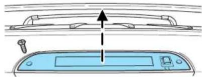
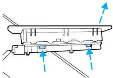
Replacinghigh-mountbrakelampbulbs
To remove the lamp assembly:
- Remove the two screws and move the lamp assembly away from the liftgate.
- Remove the bulb holder from the lamp assembly by depressing the snaps.
Lights
- Pull the bulb straight out of the socket and push in the new bulb. To complete installation, follow the removal procedure in reverse order.
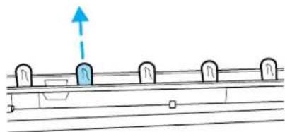
Replacingfoglampbulbs(ifequipped)
- Make sure the foglamp switch is in the OFF position.
- From underneath the vehicle, remove the harness/bulb assembly from the lamp assembly.
- Carefully disconnect the bulb from the harness assembly via the two snap clips.
Install the new bulb in reverse order.

Driver Controls
MULTI-FUNCTION LEVER
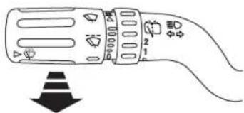
Windshieldwiper: Rotate the end of the control away from you to increase the speed of the wipers; rotate towards you to decrease the speed of the wipers.

Windshieldwasher: Push the end of the stalk:
- briefly: causes a single swipe of the wipers without washer fluid.
- a quick push and hold: the wipers will swipe three times with washer fluid.
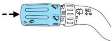
- a long push and hold: the wipers and washer fluid will be activated for up to ten seconds.
Courtesywipefeature: One extra wipe will happen a few seconds after washing the front window to clear any water that is dripping down from the top of the windshield caused by the washing.
Note: Do not operate the washer when the washer reservoir is empty. This may cause the washer pump to overheat. Check the washer fluid level frequently. Do not operate the wipers when the windshield is dry. This may scratch the glass, damage the wiper blades and cause the wiper motor to burn out. Before operating the wiper on a dry windshield, always use the windshield washer. In freezing weather, be sure the wiper blades are not frozen to the windshield before operating the wipers.
Windshield wiper features (if equipped with Autolamp feature)
The exterior lamps will turn on with the ignition on, headlamp control in the Autolamp position and the windshield wipers are turned on (for a fixed period of time).
Driver Controls
Rear window wiper/washer controls
For rear wiper operation, rotate the rear window wiper and washer control to the desired position. Select:
INT 2 — Normal speed operation of rear wiper.
INT 1 — Intermittent operation of rear wiper.
OFF — Rear wiper and washer off.
For rear wash cycle, rotate (and hold as desired) the rear wiper/washer control to either ☐ position.
From either position, the control will automatically return to the INT 2 or OFF position.

TILT STEERING WHEEL
To adjust the steering wheel:
-
Pull down the steering column tilt lever.
-
Move the steering wheel up or down until you find the desired location.
-
Push the steering column tilt lever up. This will lock the steering wheel in position.

Never adjust the steering wheel when the vehicle is


Driver Controls
ILLUMINATED VISOR MIRROR (IF EQUIPPED)
Lift the mirror cover to turn on the visor mirror lamps.

CENTER CONSOLE
Your vehicle is equipped with a variety of console features. These include:
- Cupholders
- Utility compartment console lid has a CD holder, a business card holder and two pen holders. The utility compartment has a removable bin with coin holder slots, a sliding tray, a cell phone holder and CD holders
- Rear power point
- Rear cupholders
- Small storage trays


Use only soft cups in the cupholders. Hard objects can injure you in a collision.
Driver Controls
The tray and inside bin can be removed to open up space to fit a laptop computer, MP3 players, CDs or handbags. To remove, open the console lid and pull the bin straight up and out from the console housing.

The sliding tray and inside bin can be hooked on the side or rear of the console for extra storage.

AUXILIARY POWER POINT (12V)
Poweroutletsaredesignedforaccessoryplugsonly.Donotinsert anyotherobjectinthepoweroutletasthiswilldamagethe outletandblowthefuse.Donothanganytypeofaccessoryor accessorybracketfromtheplug.Improperuseofthepower outletcancausedamagenotcoveredbyyourwarranty.
Driver Controls
The auxiliary power point is located in the instrument panel.
A second auxiliary power point is located on the rear side of the center console.
Do not use the power point for operating the cigarette lighter element (if equipped).
To prevent the fuse from being blown, do not use the power point(s) over the vehicle capacity of 12 VDC/180W. If the power point or cigar lighter socket is not working, a fuse may have blown. Refer to Fuses and Relays in the Roadside Emergencies chapter for information on checking and replacing fuses.
To prevent the battery from being discharged, do not use the power point longer than necessary when the engine is not running.
Always keep the power point caps closed when not being used.
Cigar/Cigarettelighter(ifequipped)
Do not plug optional electrical accessories into the cigarette lighter socket.
Do not hold the lighter in with your hand while it is heating, this will damage the lighter element and socket. The lighter will be released from its heating position when it is ready to be used.
Improper use of the lighter can cause damage not covered by your warranty.
Power point (110 VAC) (if equipped)
The 110 VAC power point outlet is used for powering electrical devices that require up to 150W. Exceeding the 150W limit will cause the power point to cut off the power temporarily to provide overload protection.
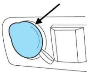
Note: The 110 VAC power point is equipped with a safety cap and a safety twist tab. They both provide protection from inserting any object into the power point other than the 110 VAC electrical device plug. The safety cap should always be in a closed position whenever the power point outlet is not in use.
The 110 VAC power point is located in the floor console in front of the gearshift.

The power outlet is not designed for the following electric appliances; they may not work properly:
• Cathode ray tube type televisions.
- Motor loads, such as vacuum cleaners, electric saws and other electric power tools, compressor-driven refrigerators, etc.
- Measuring devices, which process precise data, such as medical equipment, measuring equipment, etc.
- Other appliances requiring an extremely stable power supply: microcomputer-controlled electric blankets, touch sensor lamps, etc.
Donotkeepelectricaldevicespluggedinthepowerpoint wheneverthedeviceisnotinuse.Itisnotrecommendedtouse anyextensioncordwiththe110VACpowerpoint,sinceitwill defeatthesafetyprotectiondesignprovidedbythecapandtwist tab.Itwillalsocausethepowerpointtooverloaddueto poweringmultipledevicesthatcanreachbeyondthe150Wload limit.
The power point can switch to a fault mode when it is overloaded, overheated, or shorted. For overloading and shorting conditions, unplug your device and turn the ignition key off then on. For an overheating condition, let the system cool off, then turn the ignition key off then on.
The 110 VAC power point can provide power whenever the vehicle ignition is in the run position and the power point green indicator light located in the top left corner is turned on. Refer to the indicator light code below for the power point status.
Driver Controls
IndicatorlightCode
Green light is On — Power point is ready to supply power
Green light is Off — Power point power supply is off. Ignition is not in RUN position
Green light is blinking — Power point is in fault mode
POWER WINDOWS
Do not leave children unattended in the vehicle and do not let children play with the power windows. They may seriously injure themselves.
When closing the power windows, you should verify they are free of obstructions and ensure that children and/or pets are not in the proximity of the window openings.
Press and pull the window switches to open and close windows.
- Push down (to the first detent) and hold the switch to open.
- Pull up (to the first detent) and hold the switch to close.

One touch down
Allows the driver's window to open fully without holding the control down. Push the switch completely down to the second detent and release quickly. The window will open fully. Momentarily press the switch to any position to stop the window operation.

Driver Controls
Window lock
The window lock feature allows only the driver to operate the power windows.
To lock out all the window controls except for the driver's press the right side of the control. Press the left side to restore the window controls.
![graph TD A["Document Icon"] --> B["Output Box"] C["Document Icon"] --> B D["Document Icon"] --> B](/content/2026/05/1033069/images/704a113845ca42ebf59cded47642da5e184069ee0fe869165243e5ae798435a3.jpg)
Accessorydelay
With accessory delay, the window switches, moon roof (if equipped) and audio system may be used for up to ten minutes after the ignition switch is turned to the OFF position or until either front door is opened.
INTERIOR MIRROR
The interior rear view mirror has two pivot points on the support arm which lets you adjust the mirror UP or DOWN and from SIDE to SIDE.

Do not adjust the mirror while the vehicle is in motion.
Automatic dimming rear view mirror (if equipped)
Your vehicle may be equipped with an inside rear view mirror which has an auto-dimming function. The electronic day/night mirror will change from the normal (high reflective) state to the non-glare

(darkened) state when bright lights (glare) reach the mirror. When the mirror detects bright light from behind the vehicle, it will automatically adjust (darken) to minimize glare.
The mirror will automatically return to the normal state whenever the vehicle is placed in R (Reverse) (when the mirror is on) to ensure a bright clear view when backing up.
Donotblockthesensorsonthefrontandbackoftheinsiderear viewmirrorsincethismayimpairpropermirrorperformance.
Donotcleanthehousingorglassofanymirrorwithharsh abrasives,fuelorotherpetroleum-basedcleaningproducts.
Driver Controls
Electronic compass (if equipped)
The compass heading is displayed as one of N, NE, E, SE, S, SW, W and NW in the center stack display.
The compass reading may be affected when you drive near large buildings, bridges, power lines and powerful broadcast antenna. Magnetic or metallic objects placed in, on or near the vehicle may also affect compass accuracy.
Usually, when something affects the compass readings, the compass will correct itself after a few days of operating your vehicle in normal conditions. If the compass still appears to be inaccurate, a manual calibration may be necessary. Refer to Compasszoneadjustment.
Most geographic areas (zones) have a magnetic north compass point that varies slightly from the northerly direction on maps. This variation is four degrees between adjacent zones and will become noticeable as the vehicle crosses multiple zones. A correct zone setting will eliminate this error. Refer to Compasscalibrationadjustment.
-
Determine which magnetic zone you are in for your geographic location by referring to the zone map.
-
Turn ignition to the ON position.
-
Locate the reset button on top of the compass sensor mounted behind the mirror.
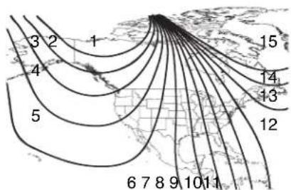

Driver Controls
- Press and hold the reset button on the compass module for approximately 5 seconds until ZONE XX appears in the center stack display.

-
Continue to press the reset button until the correct zone appears in the center stack display.
-
The direction will display after the button is released. The zone is now updated.

Compasscalibrationadjustment
Perform compass calibration in an open area free from steel structures and high voltage lines. For optimum calibration, turn off all electrical accessories (heater/air conditioning, wipers, etc.) and make sure all vehicle doors are shut.
- Start the vehicle.
- Locate the reset button on the compass sensor mounted on the base of mirror.
- To calibrate, press and hold the reset button on the compass module for approximately ten seconds until CAL appears. Release the button.
- Slowly drive the vehicle in a circle (less than 3 mph [5 km/h]) until the CAL display changes to the direction value. It may take up to five circles to complete calibration.
- The compass is now calibrated.


Driver Controls
EXTERIOR MIRRORS
Power side view mirrors

To adjust your mirrors:
- Rotate the control clockwise to adjust the right mirror and rotate the control counterclockwise to adjust the left mirror.
- Move the control in the direction you wish to tilt the mirror.
- Return to the center position to lock mirrors in place.
Fold-away mirrors
Fold the side mirrors in carefully when driving through a narrow space, like an automatic car wash.


Heated outside mirrors (if equipped)
Both mirrors are heated automatically to remove ice, mist and fog when the rear window defrost is activated.
Donotremoveicefromthe mirrorswithascraperor
attempttoreadjustthemirror glassifitisfrozeninplace.
Theseactionscouldcausedamagetotheglassandmirrors.

SPEED CONTROL
With speed control set, you can maintain a set speed without keeping your foot on the accelerator pedal.

Do not use the speed control in heavy traffic or on roads that are winding, slippery or unpaved.
Driver Controls
Setting speed control
The controls for using your speed control are located on the steering wheel for your convenience.
- Press the ON control and release it.
-
Accelerate to the desired speed.
-
Press the SET + control and release it.
-
Take your foot off the accelerator pedal.
-
The indicator light 📋 on the instrument cluster will turn on.
Note:
- Vehicle speed may vary momentarily when driving up and down a steep hill.
- If the vehicle speed increases above the set speed on a downhill, you may want to apply the brakes to reduce the speed.
- If the vehicle speed decreases more than 10 mph (16 km/h) below your set speed on an uphill, your speed control will disengage.
- If the vehicle speed decreases to 30 mph (48 km/h) or less, your speed control will disengage
Disengagingspeedcontrol
To disengage the speed control:
•Depress the brake pedal
Disengaging the speed control will not erase previous set speed.


Driver Controls
Resumingassetspeed
Press the RESUME control and release it. This will automatically return the vehicle to the previously set speed.

Increasespeedwhileusingspeedcontrol
There are three ways to set a higher speed:
- Press and hold the SET + control until you get to the desired speed, then release the control.
- Press and release the SET + control to operate the Tap-Up function. Each tap will increase the set speed by 1 mph (1.6 km/h).

- Use the accelerator pedal to get to the desired speed. When the vehicle reaches that speed press and release the SET + control.
Reducingspeedwhileusingspeedcontrol
There are three ways to reduce a set speed:
- Press and hold the SET - control until you get to the desired speed, then release the control.
- Press and release the SET - control to operate the Tap-Down function. Each tap will decrease the set speed by 1 mph (1.6 km/h).

Driver Controls
- Depress the brake pedal until the desired vehicle speed is reached, press the SET + control.
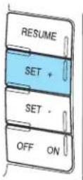
Turningoffspeedcontrol
There are two ways to turn off the speed control:
- Press the speed control OFF control.
- Turn OFF the ignition.
Note: When you turn off the speed control or the ignition, your speed control set speed memory is erased.

STEERING WHEEL CONTROLS (IF EQUIPPED)
These controls allow you to operate some audio control features.
Radio control features
Press MEDIA to select:
- AM, FM1, FM2, or CD
•LINE IN (Auxiliary input jack) (if equipped)

Driver Controls
InRadiomode:
- Press |◀◀ ▶▶| to access the next/previous preset station.
InCDmode:
- Press |◀◀ ▶▶| to listen to the next track on the disc.
In any mode:
- Press VOL + or - to adjust the volume.


MOON ROOF (IF EQUIPPED)

Do not let children play with the moon roof or leave children unattended in the vehicle. They may seriously hurt themselves.

When closing the moon roof, you should verify that it is free of obstructions and ensure that children and/or pets are not in the mity of the moon roof opening.
To operate the moon roof:
• The moon roof is equipped with an automatic, one-touch, express opening feature. Press and release the rear portion of the control. To stop motion at any time during the one-touch opening, press the control again.
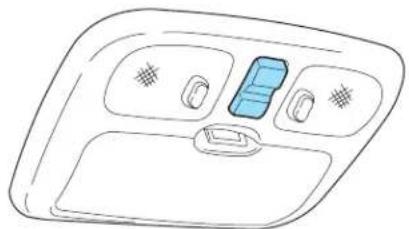
Driver Controls
- To close, press and hold the front portion of the control until the moon roof comes to a complete stop then release the control.
To operate the moon roof vent position:
- To open, press and hold the front portion of the control. This will open the vent.
- To close, press and hold the rear portion of the control until the moon roof comes to a complete stop then release the control.
Note: If the battery is disconnected, discharged, or a new battery is installed, the moon roof needs to be opened to the vent position to reset the moon roof positions.
If you open and close the moon roof repeatedly, the moon roof motor may overheat and shut down for 45 seconds while the motor cools.
MESSAGE CENTER
With the ignition in the RUN position, the message center, located on your instrument cluster, displays important vehicle and daily driving information througha
XXXXXXXXXXXXXX XXXXXXXXXXXXXX
constantmonitorofvehicle
systems. You may select display features on the message center for a display of status. The system will also notify you of potential vehicle problems with a display of system warnings followed by an indicator chime.
Selectable features
Reset
Press this control to select and reset functions shown in the INFO menu and SETUP menu.
| INFO | SETUP | RESET |
Driver Controls
Infomenu
This control displays the following control displays:
- Trip Odometer A or B
- Distance to Empty
• Average Fuel Economy (if equipped) - Instantaneous Fuel Economy (if equipped)
- Electric Energy
- Blank (odometer off)
Note: If equipped with a Navigation Screen, the Average Fuel Economy and Instantaneous Fuel Economy will display in that screen instead of the message center display.
INFO
SETUP
RESET
Odometer/Tripodometer
Refer to Gauges in the Instrument Cluster chapter.
Distancetoempty(DTE)
Selecting this function from the INFO menu will give you an estimate of how far you can drive with the fuel remaining in your tank under normal driving conditions. Remember to turn the ignition OFF XXX MILES TO E 0.0mi
when refueling your vehicle. Otherwise, the display will not show the addition of fuel for a few miles (kilometers). DTE will vary according to your driving habits.
Averagefueleconomy(AFE)(ifequipped)
Selecting this function from the INFO menu will display your average fuel economy in miles/gallon or liters/100 km.
XX.X AVE MPG 0.0 mi
If you calculate your average fuel economy by dividing miles traveled by gallons of fuel used (liters of fuel by used 100 kilometers traveled), your figure may be different than displayed for the following reasons:
- your vehicle was not perfectly level during fill-up
- differences in the automatic shut-off points on the fuel pumps at service stations
Driver Controls
-
variations in top-off procedure from one fill-up to another
•rounding off the displayed values to the nearest 0.1 gallon (liter) -
Drive the vehicle at least 5 miles (8 km) with the speed control system engaged to display a stabilized average.
- Record the highway fuel economy for future reference.
It is important to press the RESET control after setting the speed control to get accurate highway fuel economy readings.
To reset back to zero, press and hold the RESET button for 2 seconds.
Instantaneousfueleconomy(ifequipped)
Select this function from the INFO menu to display your instantaneous fuel economy. This will display your fuel economy as a Bar Graph
ranging from ▼ poor economy
to ▲ excellent economy.

Your vehicle must be moving to calculate instantaneous fuel economy. When your vehicle is not moving, this function shows ▼, one or no bars illuminated. Instantaneous fuel economy cannot be reset.
ElectricEnergy
Select this function from the INFO menu for the state of charge of the high voltage battery. For normal operation “ELECT ENERGY OK” will be displayed.
ELECT ENERGY OK
Setupmenu
Press this control for the following displays:
- Reset to English (if in another language)
- System Check
- Oil Life
- Units (English/Metric)
• Autolamp Delay (if equipped) - Autolock (if equipped)
| INFO | SETUP | RESET |
Driver Controls
• Autounlock (if equipped)
•Language
ResettoEnglish(ifinanotherlanguage)
When entering the SETUP MENU and a non-English language has been selected, "PRESS RESET FOR ENGLISH" will be displayed to change back to English.
PRESS RESET FOR ENGLISH
Press the RESET control to change back to English.
Systemcheck
Selecting this function from the SETUP menu causes the message center to cycle through each of the systems being monitored. For each of the monitored systems, the message center will indicate either RESET FOR SYSTEM CHECK
an OK message or a warning message for four seconds.
Pressing the RESET control cycles the message center through each of the systems being monitored. If you don't press any button, the system will cycle itself.
The sequence of the system check report is as follows:
- Oil life
- Electric drive
- Brake system
- Liftgate and glass
- DTE/Fuel level
Oillife
An oil change is required whenever indicated by the message center. USE ONLY RECOMMENDED ENGINE OILS.
Driver Controls
To reset the oil monitoring system to 100% after each oil change (approximately 10,000 miles [16,000 km] or 12 months) perform the following:
- Press and release the SETUP control to display "OIL LIFE = XXX% HOLD RESET = NEW".
OIL LIFE = XXX % HOLD RESET = NEW
- Press and hold the RESET control for 2 seconds and release. Oil life is set to 100% and "OIL LIFE SET TO 100%" is displayed.
OIL LIFE SET TO 100 %
- While "OIL LIFE SET TO 100%" is displayed, if a lower oil life start value is desired, press and release the RESET control to reduce the start value. Each press of the RESET control reduces the value by 10 percent.
Note: Oil life start value of 100% equals 10,000 miles [16,000 km] or 12 months. For example, setting oil life start value to 60% sets the oil life start value to 6,000 miles (9,600 km) and 219 days.
Units(English/Metric)
- Select this function from the SETUP menu for the current units to be displayed.
- Press the RESET control to change the message display from English to Metric.
Autolampdelay
This feature keeps your headlights on for up to three minutes after the ignition is switched off.
- To disable/enable the autolamp delay feature, select this function from the SETUP control for the current display mode.
- Press the RESET control to select the new Autolamp delay values of 0, 10, 20, 30, 60, 90, 120 or 180 seconds.
AUTOLAMP (SEC) lt; 0 gt; 1 0 2 0
Driver Controls
Autolock
This feature automatically locks all vehicle doors when the vehicle is shifted into any gear, putting the vehicle in motion.
-
To disable/enable the autolock feature, select this function from the SETUP control for the current display mode.
-
Press the RESET control to turn the autolock ON or OFF.
AUTOLOCK
Autounlock
This feature automatically unlocks all vehicle doors when the driver's door is opened within 10 minutes of the ignition being turned off.
-
To disable/enable the autounlock feature, select this function from the SETUP control for the current display mode.
-
Press the RESET control switch to turn the autounlock ON or OFF.
AUTOUNLOCK
Language
-
Select this function from the SETUP menu for the current language to be displayed.
-
Waiting 4 seconds or pressing the RESET control cycles the message center through each of the language choices.
LANGUAGE =
ENGLISH
Selectable languages are English, Spanish, or French.
- Press and hold the RESET control for 2 seconds to set the language choice.
Systemwarnings/information
System warnings alert you to possible problems or malfunctions in your vehicle's operating systems.
In the event of a multiple warning situation, the message center will cycle the display to show all warnings by displaying each one for four seconds.
The message center will display the last selected feature if there are no more warning messages. This allows you to use the full functionality of
Driver Controls
the message center after you acknowledge the warning by pressing the RESET control and clearing the warning message.
Warning messages that have been reset are divided into two categories:
- They will reappear on the display ten minutes from the reset.
- They will not reappear until an ignition LOCK-RUN cycle has been completed if the fault condition still exists.
This acts as a reminder that these warning conditions still exist within the vehicle.
| WarningsStatus | |
| Driver door ajar Warning cannot be reset | |
| Passenger door ajar | |
| Rear left door ajar | |
| Rear right door ajar | |
| Stop safely now Warning returns | after 10 minutes if condition still exists |
| High engine temperature | |
| High motor temperature | |
| Park brake engaged | |
| XXX miles (km) to empty fuel level low | |
| Liftgate/Glass ajar Warning returns | after the ignition key is turned from OFF to RUN. |
| Service brake system | |
| Low brake fluid | |
| Regen brakes disabled | |
| Low tire pressure | |
| Tire pressure monitor fault | |
| Tire pressure sensor fault | |
| XX% oil life change soon | |
| Oil change required | |
DRIVERDOORAJAR. Displayed when the driver door is not completely closed.
PASSENGERDOORAJAR. Displayed when the passenger door is not completely closed.
REARLEFTDOORAJAR. Displayed when the rear left door is not completely closed.
REARRIGHTDOORAJAR. Displayed when the rear right door is not completely closed.
Driver Controls
STOPSAFELYNOW. Displayed when the Master electrical hazard warning lamp is illuminated indicating a Hybrid component failure. If this warning occurs, the vehicle will soon shutdown without further warning, stop the vehicle as soon as safely possible and contact your authorized dealer as soon as possible.
HIGHENGINETEMPERATURE. Displayed when the engine coolant is overheating. Engine coolant temperature warning lamp will illuminate indicating coolant temperature is high. Stop the vehicle as soon as safely possible, turn off the engine and let it cool. Check the coolant and coolant level. Refer to Engine coolant in the Maintenance and Specifications chapter. If the warning stays on or continues to come on, contact your authorized dealer as soon as possible.
When the engine and radiator are hot, scalding coolant and steam may shoot out under pressure and cause serious injury. Do not remove the cooling system cap when the engine and radiator are hot.
HIGHMOTORTEMPERATURE. Displayed when the motor electronics are overheating. Stop the vehicle as soon as safely possible, turn off the engine and let it cool. Refer to Enginecoolant and motor/electronicscoolant in the Maintenance and Specifications chapter. If the warning stays on or continues to come on, contact your authorized dealer as soon as possible.
PARKBRAKEENGAGED. Displayed when the manual park brake is set, the engine is running and the vehicle is driven more than 3 mph (5 km). If the warning stays on after the park brake is released, contact your authorized dealer as soon as possible.
XXXMILESTOEMPTYFUELLEVELLOW. Displayed as an early reminder of a low fuel condition.
LIFTGATE/GLASSAJAR. Displayed when the liftgate or liftgate glass is not completely closed. Press RESET to reset display.
SERVICEBRAKESYSTEM. Displayed when the braking system is not operating properly. If the warning stays on or continues to come on, contact your authorized dealer as soon as possible.
LOWBRAKEFLUID. Indicates the brake fluid level is low and the brake system should be inspected immediately. Refer to Brakefluid reservoir in the Maintenance and Specifications chapter.
REGENBRAKESDISABLED. Indicates the regenerative braking system is disabled at this moment. Please see your authorized dealer if this warning remains present over several days.
Driver Controls
LOWTIREPRESSURE. Displayed when one or more tires on your vehicle have low tire pressure. Refer to Inflating Your Tires in the Tires, WheelsandLoadingchapter.
TIREPRESSUREMONITORFAULT. Displayed when the Tire Pressure Monitoring System is malfunctioning. If the warning stays on or continues to come on, have the system inspected by your authorized dealer.
TIREPRESSURESENSORFAULT. Displayed when a tire pressure sensor is malfunctioning, or your spare tire is in use. For more information on how the system operates under these conditions, refer to UnderstandingYourTirePressureMonitoringSystemin the Tires, WheelsandLoadingchapter. If the warning stays on or continues to come on, have the system inspected by your authorized dealer
XX% OILLIFECHANGESOON/OILCHANGEREQUIRED.
Displayed when the engine oil life remaining is 10% or less. When oil life left is between 10% and 0%, the XX% OIL LIFE CHANGE SOON message will be displayed. When oil life left reaches 0%, the OIL CHANGE REQUIRED message will be displayed.
LIFTGATE
- To open the liftgate window, unlock the liftgate (with the power door locks or the remote entry) and push the rightside control button under the license plate lamp shield.
- To open the liftgate, unlock the liftgate (with the power door locks or the remote entry) and push the middlecontrol button under the license plate lamp shield.
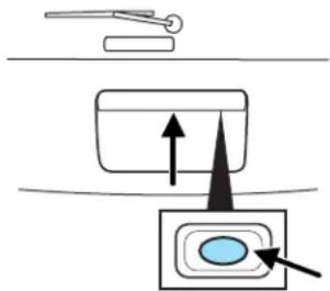
To lock the liftgate and the liftgate window, use the power door locks. Do not open the liftgate or liftgate glass in a garage or other enclosed area with a low ceiling. If the liftgate glass is raised and the liftgate is also opened, both liftgate and glass could be damaged against a low ceiling.
Do not leave the liftgate or liftgate glass open while driving. Doing so could cause serious damage to the liftgate and its components as well as allowing carbon monoxide to enter the vehicle.
Driver Controls
Make sure that the liftgate door and/or window are closed to prevent exhaust fumes from being drawn into the vehicle. Exhaust fumes contain carbon monoxide which can injure your lungs and cause drowsiness and even death. This will also prevent passengers and cargo from falling out. If you must drive with the liftgate door or window open, keep the vents open so outside air comes into the vehicle.
CARGO AREA FEATURES
Cargo shade (if equipped)
If your vehicle has a cargo shade, you can use it to cover items in the cargo area of your vehicle.
To install the shade:
- Insert the ends of the cargo shade into the mounting features located behind the rear seat on the rear trim panels.

To operate the shade:
-
Grasp the rear edge of the cargo shade and pull rearward.
-
Secure both ends of the support rod into the retention slots located on the rear quarter trim panels.
Ensure that the posts are properly latched in mounting features. The cover may cause injury in a sudden stop or accident if it is not securely installed.
Do not place any objects on the cargo area shade. They may obstruct your vision or strike occupants of vehicle in the case of a sudden stop or collision.
Driver Controls
LUGGAGE RACK
Your vehicle is equipped with a roof rack. The maximum load for the roof rack is 100 lbs (44 kg), evenly distributed on the cross-bars. If it is not possible to evenly distribute the load, position it in the center or as far forward on the cross-bars as possible.
Donotusethevehicle'sdoor handlesastiedownloops. Use thetie-downloopsonthe thumbwheelstosecureload.

Toadjustthecross-bar(ifequipped)position:
-
Loosen the thumbwheel at both ends of the cross-bar (both cross-bars are adjustable).
-
Slide the cross-bar to the desired location.
-
Tighten the thumbwheel at both ends of the cross-bar.

Driver Controls
Toremovethecross-barassembly(ifequipped)fromtheroofrack siderails:
-
Loosen the thumbwheel at both ends of the cross-bar (both cross-bars are adjustable).
-
Slide the cross-bar to the end of the rail.
-
Use a long, flat object to depress the tongue in the endcaps on both sides of the cross-bar.
- Slide the cross-bar assembly off the end of the rail.
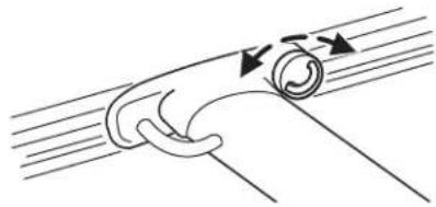


Driver Controls
Toreinstallthecross-barassembly(ifequipped)totheroofrack siderails:
- Ensure that both cross-bar assemblies are installed with the F (front) arrow facing towards the front of the vehicle.
- Use a long, flat object to depress the tongue in the endcaps on both sides of the cross-bar.
- Slide the cross-bar assemblies over the end cap tongue and into the side rails.
- Tighten thumbwheel at both ends of the cross-bar.
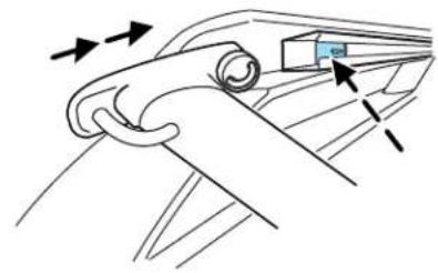

Locks and Security
KEYS
Your vehicle is equipped with two Integrated Keyhead Transmitters (IKTs). The IKT functions as both a programmed ignition key that operates all the locks and starts the vehicle, and a remote keyless entry transmitter.

Your IKTs are programmed to your vehicle; using a non-programmed key will not permit your vehicle to start. If you lose your authorized dealer supplied IKTs, replacement IKTs are available through your authorized dealer. Standard SecuriLock ® keys without remote entry transmitter functionality can also be purchased from your authorized dealer if desired.
Always carry a spare key with you in case of an emergency.
For more information regarding programming replacement IKTs, refer to the SecuriLock ™ passive anti-theft system section later in this chapter.
Note: Your vehicle's IKTs were issued with an adhesive security label on them that provides important vehicle key cut information. It is recommended that you maintain the label in a safe place for future reference, such as the inside front cover of this Owner's Guide.

2008EscapeHybrid(ehv) OwnersGuide(post-2002-fmt) USA(fus)
Locks and Security
RECOMMENDED HANDLING OF THE INTEGRATED KEYHEAD TRANSMITTER (IKT)
To avoid inadvertently activating the remote entry functions of your vehicle, it is recommended that the Integrated Keyhead Transmitter (IKT) be handled properly when starting and turning off your vehicle.
When inserting the IKT into the ignition cylinder, place your thumb on the center thumb rest of the IKT and forefinger on the logo badge on the opposite side.
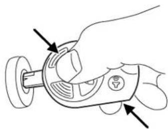
To gain more leverage when rotating the IKT in the ignition lock cylinder, you can readjust the location of your thumb to grasp the IKT on the outer edge next to the ☑ control.

Likewise, when rotating the IKT to the 1 (LOCK) position in the ignition lock cylinder, the bottom edge of the IKT adjacent to the control can be utilized.
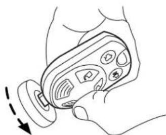
Locks and Security
POWER DOOR LOCKS
- Press the 🔒 control to unlock all doors.
- Press the 🔒 control to lock all doors.

Door key unlocking/locking
Unlockingthedoors
Turn the key in the door cylinder to unlock the driver's door only. All other doors will remain locked.
Lockingthedoors
Turn the key in the door cylinder to lock the driver's door only.
Autolock
The autolock feature will lock all the doors, liftgate and liftgate window when:
- all doors are closed,
• the ignition is in the 3 (ON) position, - you shift into any gear putting the vehicle in motion, and
• the vehicle attains a speed greater than 12 mph (20 km/h).
The autolock feature repeats when:
- any door is opened then closed while the ignition is in the 3 (ON) position and the vehicle speed is 9mph (15km / h) or lower, and
- the vehicle attains a speed greater than 12 mph (20 km/h).
Deactivating/activatingautolock
Your vehicle comes with the autolock feature enabled. There are four methods to enable/disable this feature:
- Through your authorized dealer, or
- Performing the power door lock control procedure, or
- Performing the keyless entry key pad (if equipped) procedure, or
- Performing the message center (if equipped) procedure.
Locks and Security
Note: The autolock feature can be activated/deactivated independently of the autounlock feature.
Before following the activation or deactivation procedures, make sure that the anti-theft system is not armed, ignition is in the 1 (OFF/LOCK) position, and all vehicle doors, liftgate and liftgate window are closed.
Powerdoorunlock/lockprocedure
You must complete Steps 1-5 within 30 seconds or the procedure will have to be repeated. If the procedure needs to be repeated, you must wait 30 seconds. Note: Alldoors must be closed and remain closed throughout the configuration process.
- The ignition must be off to begin sequence.
- Turn the ignition to the 3 (ON) position.
- Press the power door unlock control three times.
- Turn the ignition from the 3 (ON) to the 1 (OFF/LOCK) position.
- Press the power door unlock control three times.
- Turn the ignition back to the 3 (ON) position. The horn will chirp.
- Press the unlock control, then press the lock control. The horn will chirp once if autolock was deactivated or twice (one short and one long chirp) if autolock was activated.
- Turn the ignition to the 1 (OFF/LOCK) position. The horn will chirp once to confirm the procedure is complete.
Keylessentrykeypadprocedure
- Turn the ignition to the 1 (OFF/LOCK) position.
- Close all doors, the liftgate and liftgate window.
- Enter 5-digit entry code
- Press and hold the 3 • 4. While holding the 3 • 4 press the 7 • 8.
- Release the 7 •8.
- Release the 3 •4.
The user should receive a horn chirp to indicate the system has been disabled or a chirp followed by a honk to indicate the system has been enabled.
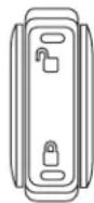
Locks and Security
Messagecenterprocedure
For information on activating/deactivating the autolock feature using the vehicle's message center (if equipped), refer to Messagecenter information in the DriverControlschapter.
Autounlock
The autounlock feature will unlock all the doors when:
- the ignition is in the 3 (RUN) position, all the doors are closed, and the vehicle has been in motion at a speed greater than 12mph (20km / h) ;
- the vehicle has then come to a stop and the ignition is turned to the 1 (OFF/LOCK) or 2 (ACC) position; and
- the driver door is opened within 10 minutes of the ignition being transitioned to the 1 (LOCK) or 2 (ACC) position.
Note: The doors will not autounlock if the vehicle has been electronically locked before the driver door is opened.
Deactivating/activatingautounlock
Your vehicle comes with the autounlock feature activated. There are four methods to enable/disable this feature:
- Through your authorized dealer, or
• by using the power door unlock/lock sequence, - Performing the keyless entry key pad procedure (if equipped), or
- by using the instrument cluster message center (if equipped). Refer to Messagecenter in the DriverControlschapter.
Note: The autounlock feature can be activated/deactivated independently of the autolock feature.
Powerdoorlockswitchautounlockenable/disableprocedure
Before starting, ensure the ignition is in the 1 (LOCK) position and all vehicle doors are closed. You must complete Steps 1–5 within 30 seconds or the procedure will have to be repeated. If the procedure needs to be repeated, wait a minimum of 30 seconds before beginning again.

- Place the key in the ignition and turn the ignition to the 3 (RUN) position.
Locks and Security
- Press the power door unlock control on the door panel three times.
- Turn the ignition from the 3 (RUN) position to the 1 (LOCK) position.
- Press the power door unlock control on the door panel three times.
- Turn the ignition back to the 3 (RUN) position. The horn will chirp one time to confirm programming mode has been entered and is active.
- To enable/disable the autounlock feature, press the lock control, then press the unlock control. The horn will chirp once if autounlock was deactivated or twice (one short and one long chirp) if autounlock was activated.
- Turn the ignition to the 1 (LOCK) position. The horn will chirp once to confirm the procedure is complete.
Keylessentrykeypadautounlockenable/disableprocedure
- Turn the ignition to the 1 (LOCK) position.
- Close all doors.
- Enter factory-set 5-digit entry code.
- Press and hold the 3 • 4. While holding the 3 • 4, press and release the 7 • 8. While still holding the 3 • 4, press and release the 7 • 8 a second time.
- Release the 3 •4.
The user should receive a hornchirpto indicate the system has been disabled or a chirp followed by a honk to indicate the system has been enabled.
Messagecenterprocedure
For information on activating/deactivating the autounlock feature using the vehicle's message center (if equipped), refer to Messagecenter information in the DriverControlschapter.
Smart unlocking feature
The smart unlocking feature helps prevent you from locking yourself out of the vehicle. With the key in any ignition position, the driver's door will automatically unlock if it is locked using the power lock control on the driver's door panel while the driver's door is open.
Locks and Security
CHILDPROOF DOOR LOCKS
When these locks are set, the rear doors cannot be opened from the inside. The rear doors can be opened from the outside when the doors are unlocked.
The childproof locks are located on rear edge of each rear door and must be set separately for each door.
NOTE: Setting the lock for one door will not automatically set the lock for both doors so you must set each child lock on each door separately.
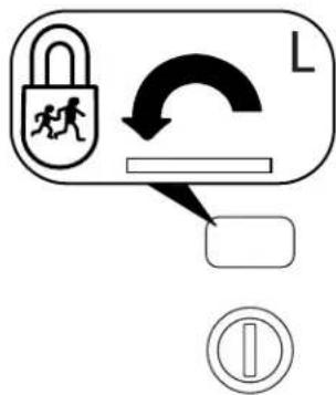
Insert the key and turn in the direction of arrow shown on the door to engage the child proof lock. Turn in the opposite direction to disengage childproof locks.
REMOTE ENTRY SYSTEM (IF EQUIPPED)
The Integrated Keyhead Transmitter (IKT) complies with part 15 of the FCC rules and with RSS-210 of Industry Canada. Operation is subject to the following two conditions: (1) This device may not cause harmful interference, and (2) This device must accept any interference received, including interference that may cause undesired operation.
Changesormodificationsnotexpresslyapprovedbytheparty responsibleforcompliancecouldvoidtheuser'sauthorityto operatetheequipment.
Locks and Security
The typical operating range for your IKT is approximately 33 feet (10 meters). A decrease in operating range could be caused by:
- weather conditions,
•nearby radio towers, - structures around the vehicle, or
- other vehicles parked next to your vehicle.
The IKT allows you to:
- remotely unlock the vehicle doors.
- remotely lock all the vehicle doors.
- remotely open the power liftgate glass.
- activate the personal alarm.
• operate the illuminated entry feature.
The remote entry lock/unlock feature operates in any ignition position except while the key is held in the 4 (START) position. The panic feature operates with the key in the 1 (LOCK) position.
If there are problems with the remote entry system, make sure to take ALLIntegratedKeyheadTransmitters with you to the authorized dealer in order to aid in troubleshooting the problem.

Two step door unlocking
- Press and release to unlock the driver's door. Note: The interior lamps will illuminate if the lamp is in the DOOR position.
- Press ☐ and release again within three seconds to unlock the passenger doors, the liftgate and liftgate glass.
The battery saver feature will turn off the interior lamps 10 minutes after the ignition is turned to the 1 (OFF/LOCK) position.
Onestepdoorunlocking
If the one step door unlocking feature is activated, press 📋 and release once to unlock all of the doors, the liftgate and liftgate glass. Note: The interior lamps will illuminate (refer to Illuminatedentryinformation later in this section), if the control on the overhead lamp is in the DOOR position.
Locks and Security
Switchingfromtwosteptoonestepdoorunlocking
Unlocking can be switched between two step and one step door unlocking by pressing and holding both 🔒 and buttons simultaneously on the remote entry transmitter for approximately 4 seconds. The turn signal will flash twice to indicate that the vehicle has switched to one step unlocking. Repeat the procedure to switch back to two step unlocking.
Locking the doors
- Press and release to lock all the doors. Assuming all vehicle doors and the liftgate are properly closed and the park/turn lamps will flash once.
- Press 🔒 and release again within three seconds to confirm that all the doors and liftgate are closed and locked. Note: The doors will lock again and the horn will chirp once.
If any of the doors or the hood are not properly closed, the horn will chirp twice and park/turn lamps will not flash when the 📄 control is pressed.
Opening the liftgate (if equipped) 2x
Press twice within 3 seconds to open the liftgate glass.
Car finder
Press twice within 3 seconds. The horn will chirp and the turn lamps will flash. It is recommended that this method be used to locate your vehicle, rather than using the panic alarm.
Sounding a panic alarm
Press and hold ⬆ for 1.5 seconds to activate the alarm. To deactivate the feature, press the control again, turn the ignition to the 3 (RUN) or 4 (START) position, or wait for the alarm to time out in approximately 3 minutes.
Note: The panic alarm will only operate when the ignition is in the 1 (LOCK) position.
Replacing the battery
The Integrated Keyhead Transmitter uses one coin type three-volt lithium battery CR2032 or equivalent.
Locks and Security
To replace the battery:
- Twist a thin coin in the slot of the IKT near the key ring in order to remove the battery cover.

- Do not wipe off any grease on the battery terminals on the back surface of the circuit board.

- Remove the old battery. Note: Please refer to local regulations when disposing of transmitter batteries.
- Insert the new battery. Refer to the instructions inside the IKT for the correct orientation of the battery. Press the battery down to ensure that the battery is fully seated in the battery housing cavity.
- Snap the battery cover back onto the key.
Note: Replacement of the battery will not cause the IKT to become deprogrammed from your vehicle. The IKT should operate normally after battery replacement.
Replacing lost Integrated Keyhead Transmitters (IKTs)
If you would like to have your Integrated Keyhead Transmitters reprogrammed because you lost one, or would like to buy additional IKTs, you can either reprogram them yourself, or take allIKTsto your authorized dealer for reprogramming.
HowtoreprogramyourIntegratedKeyheadTransmitters(IKTs)
To program a new Integrated Keyhead Transmitter yourself, refer to Programmingsparekeys in the SecuriLock ® passiveanti-theft section of this chapter. Note: At least two IKTs are required to perform this procedure yourself.
Locks and Security
Illuminated entry
The interior lamps and puddle lamps (if equipped) illuminate when the Integrated Keyhead Transmitter or the keyless entry system keypad is used to unlock the door(s).
The illuminated entry system will turn off the interior lights if:
• the ignition is turned to the 3 (RUN) position, or
- the Integrated Keyhead Transmitter lock control is pressed, or
- the vehicle is locked using the keyless entry keypad (if equipped), or
• after 25 seconds of illumination.
The inside lights will not turn off if:
- they have been turned on with the dimmer control, or
- any door is open.
Illuminatedexit
- The interior lights will illuminate when the key is removed from the ignition.
The lamps automatically turn off after 25 seconds. The dome and cargo lamp controls must not be set to the OFF position for the illuminated exit system to operate.
Perimeter lamps illuminated entry
With the Integrated Keyhead Transmitter system, the following items will illuminate when the ☐ (unlock) control on the transmitter is pressed:
- Head lamps
- Park lamps
- Tail lamps
The lamps will automatically turn off:
- if the ignition switch is turned to the 3 (RUN) position, or
• the IKT 🔒 (lock) control is pressed, or
• after 25 seconds of illumination.
Note: On some vehicles, the perimeter lamps illuminated entry feature will not activate in daylight conditions.
Deactivating/activatingperimeterlampsilluminatedentry
You may enable/disable this feature by having your vehicle serviced by your authorized dealer.
Locks and Security
You may also perform the following power door lock sequence to enable/disable the perimeter lamps feature. Note: Before starting, ensure the ignition is in the 1 (LOCK) position and all vehicle doors are closed. You must complete Steps 1–5 within 30 seconds or the procedure will have to be repeated. If the procedure needs to be repeated, wait a minimum of 30 seconds before beginning again.
-
The ignition must be OFF to begin the sequence.
-
Place the key in the ignition and turn the ignition to the 3 (RUN) position.
-
Press the power door unlock control on the door panel three times.
-
Turn the ignition from the 3 (RUN) position to the 1 (LOCK) position.
-
Press the power door unlock control on the door panel three times.
-
Turn the ignition back to the 3 (RUN) position. The horn will chirp one time to confirm programming mode has been entered and is active.
-
Press the power door unlock control twice within 5 seconds. Note: The horn will chirp once to indicate the perimeter lighting feature has been deactivated. The horn will chirp once and honk once (one short and one long) to indicate the perimeter lighting feature has been activated.
-
Turn the ignition to the 1 (LOCK) position to exit the procedure. Note: The horn will chirp once to confirm the procedure is complete.
![graph TD A["1"] --> B["2"] B --> C["3"] C --> D["4"]](/content/2026/05/1033069/images/daaa7dcccd015849df5b15510ea8538214f092d07c649970159ea0d0599b8ecf.jpg)
SECURILOCK®PASSIVE ANTI-THEFT SYSTEM
SecuriLock® passive anti-theft system is an engine immobilization system. This system is designed to help prevent the engine from being started unless a codedIntegratedKeyheadTransmitter(IKT) programmedtoyourvehicleis used. The use of the wrong type of coded key may lead to a "no-start" condition.
Your vehicle comes with two coded Integrated Keyhead Transmitters; additional coded IKTs may be purchased from your authorized dealer. Standard SecuriLock® keys without remote entry transmitter functionality can also be purchased from your authorized dealer if desired. The authorized dealer can program your spare IKTs to your
Locks and Security
vehicle or you can program the IKTs yourself. Refer to Programming spareIntegratedKeyheadTransmitters for instructions on how to program the coded key.
Note: The SecuriLock ™ passive anti-theft system is not compatible with non-Ford aftermarket remote start systems. Use of these systems may result in vehicle starting problems and a loss of security protection.
Note: Large metallic objects, electronic devices that are used to purchase gasoline or similar items, or a second coded key on the same key chain may cause vehicle starting issues. You need to prevent these objects from touching the coded IKT while starting the engine. These objects will not cause damage to the coded IKT, but may cause a momentary issue if they are too close to the IKT when starting the engine. If a problem occurs, turn the ignition off, remove all objects on the key chain away from the coded IKT and restart the engine.
Anti-theft indicator
The anti-theft indicator is located in the instrument panel cluster.
- When the ignition is in the 1 (LOCK) position, the indicator will flash once every 2 seconds to indicate the SecuriLock® system is functioning as a theft deterrent.

- When the ignition is in the 3 (RUN) position, the indicator will glow for 3 seconds to indicate normal system functionality.
If a problem occurs with the SecuriLock ™ system, the indicator will flash rapidly or glow steadily when the ignition is in the 3 (RUN) position. If this occurs, the vehicle will not start and should be taken to an authorized dealer for service.
Automatic arming
The vehicle is armed immediately after switching the ignition to the 1 (LOCK) position.
The theft indicator will flash every two seconds to act as a theft deterrent when the vehicle is armed.

Automatic disarming
The vehicle is disarmed immediately after the ignition is turned to the 3 (RUN) position.
Locks and Security
The theft indicator will illuminate for three seconds and then go out. If the theft indicator stays on for an extended period of time or flashes rapidly, have the system serviced by your authorized dealer.
Replacement Integrated Keyless Transmitters (IKT) and coded keys
Note: Your vehicle comes equipped with two Integrated Keyhead Transmitters (IKTs). The IKT functions as both a programmed ignition key that operates all the locks and starts the vehicle, as well as a remote keyless entry transmitter. A maximum of eight coded keys can be programmed to your vehicle; only four of these eight keys can be IKTs with remote entry functionality.
If your IKTs or standard SecuriLock ™ coded keys are lost or stolen and you don't have an extra coded key, you will need to have your vehicle towed to an authorized dealer. The key codes need to be erased from your vehicle and new coded keys will need to be programmed.
Replacing coded keys can be very costly. Store an extra programmed key away from the vehicle in a safe place to help prevent any inconveniences. Please visit an authorized dealer to purchase additional spare or replacement keys.
Programming spare keys
You can program your own Integrated Keyhead Transmitters or standard SecuriLock ™ coded keys to your vehicle. This procedure will program both the engine immobilizer keycode and the remote entry transmitter portion of the IKT to your vehicle. Note: A maximum of eight coded keys can be programmed to your vehicle; only four of these eight can be IKTs with remote entry functionality.
Tips:
- Only use Integrated Keyhead Transmitters (IKTs) or standard SecuriLock™ keys.
- You must have two previously programmed coded keys (keys that already operate your vehicle's engine) and the new unprogrammed key(s) readily accessible.
- If two previously programmed coded keys are not available, you must take your vehicle to your authorized dealer to have the spare key(s) programmed.
Locks and Security
Please read and understand the entire procedure before you begin.
- Insert the first previously programmed codedkey into the ignition.
![graph TD A["1"] --> B["2"] B --> C["3"] C --> D["4"]](/content/2026/05/1033069/images/88fe8311c7101b95955563aca40db9b0ab75c55b90e966e537518d788135f7a6.jpg)
- Turn the ignition from the 1 (LOCK) position to the 3 (RUN) position. Keep the ignition in the 3 (RUN) position for at least three seconds, but no more than 10 seconds.
- Turn the ignition to the 1 (LOCK) position and remove the first coded key from the ignition.
- Within ten seconds of turning the ignition to the 1 (LOCK) position, insert the second previously codedkey into the ignition.
- Turn the ignition from the 1 (LOCK) position to the 3 (RUN) position. Keep the ignition in the 3 (RUN) position for at least three seconds, but no more than 10 seconds.
- Turn the ignition to the 1 (LOCK) position and remove the second previously programmed codedkey from the ignition.
- Within twenty seconds of turning the ignition to the 1 (LOCK) position and removing the previously programmed codedkey, insert the new unprogrammed key (new key/valet key) into the ignition.
- Turn the ignition from the 1 (LOCK) position to the 3 (RUN) position. Keep the ignition in the 3 (RUN) position for at least six seconds.
- Remove the newly programmed codedkey from the ignition.
If the key has been successfully programmed it will start the vehicle's engine and will operate the remote entry system (if the new key is an Integrated Keyhead Transmitter). The theft indicator light will illuminate for three seconds and then go out to indicate successful programming.
If the key was not successfully programmed, it will not start your vehicle's engine and/or will not operate the remote entry features. The theft indicator light may flash on and off. Wait 20 seconds and you may repeat Steps 1 through 8. If failure repeats, bring your vehicle to your authorized dealer to have the new key(s) programmed.
To program additional new unprogrammed key(s), wait twenty seconds and then repeat this procedure from Step 1.
Seating and Safety Restraints
FRONT SEATS
Notes:
Reclining the seatback can cause an occupant to slide under the seat's safety belt, resulting in severe personal injuries in the event of a collision.
Do not pile cargo higher than the seatbacks to reduce the risk of injury in a collision or sudden stop.
Before returning the seatback to its original position, make sure that cargo or any objects are not trapped behind the seatback. After returning the seatback to its original position, pull on the seatback to ensure that it has fully latched. An unlatched seat may become dangerous in the event of a sudden stop or collision.
Adjustable head restraints
The purpose of these head restraints is to help limit head motion in the event of a rear collision. To properly adjust your head restraints, lift the head restraint so that it is located directly behind your head or as close to that position as possible.
The head restraints can be moved up and down.

Seating and Safety Restraints
Push side control and push down on head restraint to lower it.

Adjusting the front manual seat (if equipped)
Lift handle to move seat forward or backward.

Pull lever up to adjust seatback.

Adjusting the front power seat (if equipped)

Never adjust the driver's seat or seatback when the vehicle is moving.
Seating and Safety Restraints

Do not pile cargo higher than the seatbacks to avoid injuring people in a collision or sudden stop.

Always drive and ride with your seatback upright and the lap belt snug and low across the hips.

Reclining the seatback can cause an occupant to slide under the seat's safety belt, resulting in severe personal injuries in the of a collision.

Sitting improperly out of position or with the seat back reclined too far can take off weight from the seat cushion and affect the on of the passenger sensing system, resulting in serious injury or in a crash. Always sit upright against your seatback, with your n the floor.

To reduce the risk of possible serious injury: Do not hang objects off seat back or stow objects in the seatback map pocket (if ped) when a child is in the front passenger seat. Do not place its underneath the front passenger seat or between the seat and enter console (if equipped). Check the "passenger airbag off" or "airbag off" indicator lamp for proper airbag status. Refer to Frontingersensingsystemsection for additional details. Failure to these instructions may interfere with the front passenger seating system.
The control is located on the outboard side of the seat cushion.
Press to raise or lower the front portion of the seat cushion.

Seating and Safety Restraints
Press to raise or lower the rear portion of the seat cushion.

Press the control to move the seat forward, backward, up or down.

Heated seats (if equipped)
To operate the heated seats:
- Push the button located on the instrument panel to activate.
- Push again to deactivate.

The heated seats will activate when the ignition is in the RUN position. The system automatically shuts off after 10 minutes.
REAR SEATS
Head restraints
The purpose of these head restraints is to help limit head motion in the event of a rear collision. To properly adjust your head restraints, lift the head restraint so that it is located directly behind your head or as close to that position as possible.
Seating and Safety Restraints
The head restraints can be moved up and down. Lift the head restraint so that it is located directly or as close as possible behind your head.
Push control to lower or remove head restraint.
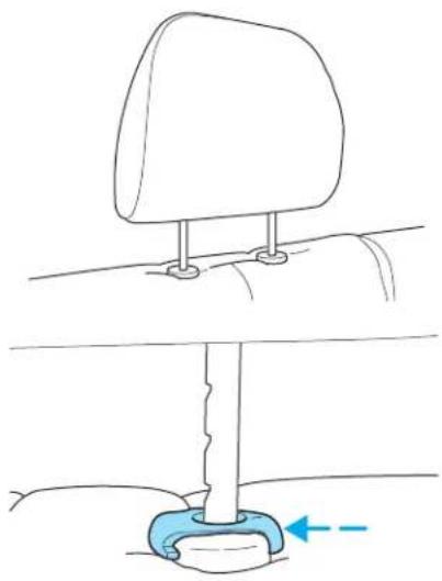
Folding down rear seats
-
Raise the rear seat head restraint and remove.
-
Place the head restraint under the front seat for storage.

2008EscapeHybrid(ehv) OwnersGuide(post-2002-fmt) USA(fus)
Seating and Safety Restraints
- Pull the seat release control.
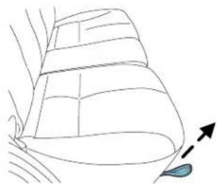
Note: Make sure the floor is clear of all objects before folding the seat.
- Flip seat forward.

Attach the safety belt web snap button to the quarter trim panel snap button. This will ensure that safety belt does not get caught by staying out of the seat back folding path.

102
2008EscapeHybrid(ehv) OwnersGuide(post-2002-fmt) USA(fus)
Seating and Safety Restraints
- To release seatback, pull the seatback release lever (on top of seat) toward the front seat. This is common for both 60% and 40% seatbacks.
Note: When the seatback release lever is pulled, slowly lower seatback to the flat position.

- Rotate seatback down into load floor position.

Returningtherearseatstouprightposition
- Pull seatback up and into upright position making sure seatback locks into place and the red seat unlatched indicator on release paddle is not visible.

2008EscapeHybrid(ehv) OwnersGuide(post-2002-fmt) USA(fus)
Seating and Safety Restraints
- Rotate seat cushion down into the seating position making sure that the seat cushion is locked into place and that the safety belt buckles are exposed.

Make sure safety belt buckle heads are through elastic
holders on seat backs. Safety belt buckles may break if they are trapped underneath the seatback as the seatback is rotated down.
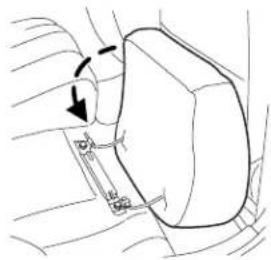

Before returning the seatback to its original position, make sure that cargo or any objects are not trapped behind the seatback.
After returning the seatback to its original position, reinstall the head restraints, and pull on the seatback to ensure that it has fully latched. An unlatched seat may become dangerous in the event of a sudden stop or collision.

Remove the head restraint stored under the front set return it to the original
position on the seatback. Failure to do so could result in personal injury.

- Unsnap the safety belt webbing from the quarter trim panel.
Seating and Safety Restraints
Toremovetherearcushion
- Lift the yellow tab to release the hinges.
- Pull the cushion to the outboard side of the vehicle.

Toinstalltherearcushion
- Push the cushion to the inboard side of the vehicle.
- Make sure that the hinges are locked into place.

SAFETY RESTRAINTS
Personal Safety System™
The Personal Safety System ® provides an improved overall level of frontal crash protection to front seat occupants and is designed to help further reduce the risk of airbag-related injuries. The system is able to analyze different occupant conditions and crash severity before activating the appropriate safety devices to help better protect a range of occupants in a variety of frontal crash situations.
Your vehicle's Personal Safety System TM consists of:
- Driver and passenger dual-stage airbag supplemental restraints.
- Front safety belts with pretensioners, energy management retractors, and safety belt usage sensors.
- Driver's seat position sensor
•Front passenger sensing system
Seating and Safety Restraints
- "Passenger airbag off" or "pass airbag off" indicator lamp
•Front crash severity sensor. - Restraints Control Module (RCM) with impact and safing sensors.
- Restraint system warning light and back-up tone.
- The electrical wiring for the airbags, crash sensor(s), safety belt pretensioners, front safety belt usage sensors, driver seat position sensor, front passenger sensing system, and indicator lights.
HowdoesthePersonalSafetySystem ™ work?
The Personal Safety System® can adapt the deployment strategy of your vehicle's safety devices according to crash severity and occupant conditions. A collection of crash and occupant sensors provides information to the Restraints control module (RCM). During a crash, the RCM activates the safety belt pretensioners and/or either one or both stages of the dual-stage airbag supplemental restraints based on crash severity and occupant conditions.
The fact that the pretensioners or airbags did not activate for both front seat occupants in a collision does not mean that something is wrong with the system. Rather, it means the Personal Safety System ® determined the accident conditions (crash severity, belt usage, etc.) were not appropriate to activate these safety devices. Front airbags are designed to activate only in frontal and near-frontal collisions (not rollovers, side impacts or rear impacts) unless the collision causes sufficient longitudinal deceleration. The pretensioners are designed to activate in frontal, and in side collisions and rollovers.
Driverandpassengerdual-stageairbagsupplementalrestraints
The dual-stage airbags offer the capability to tailor the level of airbag inflation energy. A lower, less forceful energy level is provided for more common, moderate-severity impacts. A higher energy level is used for the most severe impacts. Refer to Airbagsupplementalrestraints section in this chapter.
Frontcrashseveritysensor
The front crash severity sensor enhances the ability to detect the severity of an impact. Positioned up front, it provides valuable information early in the crash event on the severity of the impact. This allows your Personal Safety System 79 to distinguish between different levels of crash severity and modify the deployment strategy of the dual-stage airbags and safety belt pretensioners.
Driver'sseatpositionsensor
The driver's seat position sensor allows your Personal Safety System 134 to tailor the deployment level of the driver dual-stage airbag based on seat
Seating and Safety Restraints
position. The system is designed to help protect smaller drivers sitting close to the driver airbag by providing a lower airbag output level.
Frontpassengersensingsystem
For airbags to do their job they must inflate with great force, and this force can pose a potentially deadly risk to occupants that are very close to the airbag when it begins to inflate. For some occupants, like infants in rear-facing child seats, this occurs because they are initially sitting very close to the airbag. For other occupants, this occurs when the occupant is not properly restrained by safety belts or child safety seats and they move forward during pre-crash braking. The most effective way to reduce the risk of unnecessary injuries is to make sure all occupants are properly restrained. Accident statistics suggest that children are much safer when properly restrained in the rear seating positions than in the front.

Air bags can kill or injure a child in a child seat. NEVERplace a rear-facing child seat in front of an active air bag. If you must forward-facing child seat in the front seat, move the seat all the ack.

Always transport children 12 years old and under in the back seat and always properly use appropriate child restraints.
The front passenger sensing system can automatically turn off the passenger front airbag. The system is designed to help protect small (child size) occupants from airbag deployments when they are improperly seated or restrained in the front passenger seat contrary to proper child-scating or restraint usage recommendations. Even with this technology, parents are STRONGLY encouraged to always properly restrain children in the rear seat. The sensor also turns off the passenger front airbag and passenger seat-mounted side airbag when the passenger seat is empty.
When the front passenger seat is occupied and the sensing system has turned off the passenger's frontal airbag, the "pass airbag off" indicator will light and stay lit to remind you that the front passenger frontal airbag is off. See Frontpassengersensingsystemin the airbags section of this chapter.
Frontsafetybeltusagesensors
The front safety belt usage sensors detect whether or not the driver and front outboard passenger safety belts are fastened. This information
Seating and Safety Restraints
allows your Personal Safety System ™ to tailor the airbag deployment and safety belt pretensioner activation depending upon safety belt usage. Refer to Safetyrestraintssection in this chapter.
Frontsafetybeltpretensioners
The safety belt pretensioners at the front outboard seating positions are designed to tighten the safety belts firmly against the occupant's body during frontal collisions, and in side collisions and rollovers. This helps increase the effectiveness of the safety belts. In frontal collisions, the safety belt pretensioners can be activated alone or, if the collision is of sufficient severity, together with the front airbags.
Frontsafetybeltenergymanagementretractors
The front outboard safety belt energy management retractors allow webbing to be pulled out of the retractor in a gradual and controlled manner in response to the occupant's forward momentum. This helps reduce the risk of force-related injuries to the occupant's chest by limiting the load on the occupant. Refer to Energymanagementfeature section in this chapter.
DeterminingifthePersonalSafetySystem 16 isoperational
The Personal Safety System ® uses a warning light in the instrument cluster or a back-up tone to indicate the condition of the system. Refer to the Warning light section in the Instrument Cluster chapter. Routine maintenance of the Personal Safety System ® is not required.
The Restraints control module (RCM) monitors its own internal circuits and the circuits for the airbag supplemental restraints, crash sensor(s), safety belt pretensioners, front safety belt buckle sensors, driver seat position sensor, and front passenger sensing system. In addition, the RCM also monitors the restraints warning light in the instrument cluster. A difficulty with the system is indicated by one or more of the following.
- The warning light will either flash or stay lit.
- The warning light will not illuminate immediately after ignition is turned on.
- A series of five beeps will be heard. The tone pattern will repeat periodically until the problem and warning light are repaired.
If any of these things happen, even intermittently, have the Personal Safety System ™ serviced at an authorized dealer immediately. Unless serviced, the system may not function properly in the event of a collision.
Seating and Safety Restraints
Safety restraints precautions

Always drive and ride with your seatback upright and the lap belt snug and low across the hips.

To reduce the risk of injury, make sure children sit where they can be properly restrained.

Never let a passenger hold a child on his or her lap while the vehicle is moving. The passenger cannot protect the child from in a collision.

All occupants of the vehicle, including the driver, should always properly wear their safety belts, even when an airbag emental restraint system (SRS) is provided.

It is extremely dangerous to ride in a cargo area, inside or outside of a vehicle. In a collision, people riding in these areas are more likely to be seriously injured or killed. Do not allow people to turn any area of your vehicle that is not equipped with seats and have belts. Be sure everyone in your vehicle is in a seat and using a very belt properly.

In a rollover crash, an unbelted person is significantly more likely to die than a person wearing a safety belt.

Each seating position in your vehicle has a specific safety belt assembly which is made up of one buckle and one tongue that designed to be used as a pair. 1) Use the shoulder belt on the side shoulder only. Never wear the shoulder belt under the arm. Ever swing the safety belt around your neck over the inside der. 3) Never use a single belt for more than one person.

Always transport children 12 years old and under in the back seat and always properly use appropriate child restraints.
Seating and Safety Restraints

Safety belts and seats can become hot in a vehicle that has been closed up in sunny weather; they could burn a small child. Check overs and buckles before you place a child anywhere near them.
Combination lap and shoulder belts
- Insert the belt tongue into the proper buckle (the buckle closest to the direction the tongue is coming from) until you hear a snap and feel it latch. Make sure the tongue is securely fastened in the buckle.

- To unfasten, push the release button and remove the tongue from the buckle.

Energy Management Feature
- This vehicle has a safety belt system with an energy management feature at the front outboard seating positions to help further reduce the risk of injury in the event of a head-on collision.
- The front outboard safety belt system has a retractor assembly that is designed to extend the safety belt webbing in a controlled manner. This helps reduce the belt force acting on the user's chest.
All safety belts in the vehicle are combination lap and shoulder belts. The passenger safety belts have two types of locking modes described below:
Vehicle sensitive mode
This is the normal retractor mode, which allows free shoulder belt length adjustment to your movements and locking in response to vehicle
Seating and Safety Restraints
movement. For example, if the driver brakes suddenly or turns a corner sharply, or the vehicle receives an impact of approximately 5 mph (8 km/h) or more, the combination safety belts will lock to help reduce forward movement of the driver and passengers.
Automatic locking mode
Whentousetheautomaticlockingmode
In this mode, the shoulder belt is automatically pre-locked. The belt will still retract to remove any slack in the shoulder belt. The automatic locking mode is not available on the driver safety belt.
This mode should be used anytimea child safety seat, except a booster, is installed in passenger front or rear seating positions. Children 12 years old and under should be properly restrained in the rear seat whenever possible. Refer to Safetyrestraintsforchildrenor Safety seatsforchildrenlater in this chapter.
Howtousetheautomaticlockingmode
- Buckle the combination lap and shoulder belt.

- Grasp the shoulder portion and pull downward until the entire belt is pulled out.

- Allow the belt to retract. As the belt retracts, you will hear a clicking sound. This indicates the safety belt is now in the automatic locking mode.
Seating and Safety Restraints
Howtodisengagetheautomaticlockingmode
Disconnect the combination lap/shoulder belt and allow it to retract completely to disengage the automatic locking mode and activate the vehicle sensitive (emergency) locking mode.
After any vehicle collision, the safety belt systems at all seating positions (except the driver position, which doesn't have this feature) must be checked by an authorized dealer to verify that the automatic locking retractor feature for child seats is still functioning properly. In addition, all safety belts should be checked for proper function.
BELT AND RETRACTOR ASSEMBLY MUST BE REPLACED if the safety belt assembly “automatic locking retractor” feature or any other safety belt function is not operating properly when checked by an authorized dealer. Failure to replace the Belt and Retractor assembly could increase the risk of injury in collisions.
Safety belt height adjustment
Your vehicle has safety belt height adjustments at the front outboard seating positions. Adjust the height of the shoulder belt so the belt rests across the middle of your shoulder.
To adjust the shoulder belt height, squeeze and hold the buttons on the side and slide the height adjuster up or down. Release the buttons and pull down on the height adjuster to make sure it is locked in place.

Position the safety belt height adjusters so that the belt rests across the middle of your shoulder. Failure to adjust the safety belt properly could reduce the effectiveness of the safety belt and increase the risk of injury in a collision.
Safety belt pretensioner
Your vehicle is equipped with safety belt pretensioners at the driver and front passenger seating positions.
Seating and Safety Restraints
The safety belt pretensioners activate during frontal collisions, and in side collisions and rollovers. A safety belt pretensioner is a device which tightens the webbing of the lap and shoulder belts in such a way that they fit more snugly against the body.
The driver and front passenger safety belt system (including retractors, buckles and height adjusters) must be replaced if the vehicle is involved in a collision that results in deployment of front airbags, seat-mounted side airbags and Safety Canopy ™ , and safety belt pretensioners.
Failure to replace the safety belt assembly under the above conditions could result in severe personal injuries in the event of a collision.
Safety belt extension assembly
If the safety belt is too short when fully extended, a 9 inch (23 cm) or 12 inch (31 cm) safety belt extension assembly can be added (part numbers 611C22-A and 611C22-B respectively). These assemblies can be obtained from an authorized dealer.
Use only extensions manufactured by the same supplier as the safety belt. Manufacturer identification is located at the end of the webbing on the label. Also, use the safety belt extension only if the safety belt is too short for you when fully extended.
Do not use extensions to change the fit of the shoulder belt across the torso.
Safety belt maintenance
Inspect the safety belt systems periodically to make sure they work properly and are not damaged. Inspect the safety belts to make sure there are no nicks, tears or cuts. Replace if necessary. All safety belt assemblies, including retractors, buckles, front safety belt buckle assemblies, buckle support assemblies (slide bar-if equipped), shoulder belt height adjusters (if equipped), shoulder belt guide on seatback (if equipped), child safety seat LATCH and tether anchors, and attaching hardware, should be inspected after a collision. Ford Motor Company recommends that all safety belt assemblies in use in vehicles involved in a collision be replaced. However, if the collision was minor and an
Seating and Safety Restraints
authorized dealer finds that the belts do not show damage and continue to operate properly, they do not need to be replaced. Safety belt assemblies not in use during a collision should also be inspected and replaced if either damage or improper operation is noted.

Failure to inspect and if necessary replace the safety belt assembly under the above conditions could result in several injuries in the event of a collision.
For proper care of soiled safety belts, refer to Interior in the Cleaning chapter.
Safety belt warning light and indicator chime
The safety belt warning light illuminates in the instrument cluster and a chime sounds to remind the occupants to fasten their safety belts.
Conditionsofoperation
| If...Then... | |
| The driver's safety belt is not buckled before the ignition switch is turned to the ON position... | The safety belt warning light illuminates 1 minute and the warning chime sounds 6 seconds. |
| The driver's safety belt is buckled while the indicator light is illuminated and the warning chime is sounding... | The safety belt warning light and warning chime turn off. |
| The driver's safety belt is buckled before the ignition switch is turned to the ON position... | The safety belt warning light and indicator chime remain off. |
Belt-Minder®
The Belt-Minder® feature is a supplemental warning to the safety belt warning function. This feature provides additional reminders by intermittently sounding a chime and illuminating the safety belt warning lamp in the instrument cluster when the driver's and front passenger's safety belt is unbuckled.
The Belt-Minder®feature uses information from the front passenger sensing system to determine if a front seat passenger is present and
Seating and Safety Restraints
therefore potentially in need of a warning. To avoid activating the Belt-Minder® feature for objects placed in the front passenger seat, warnings will only be given to large front seat occupants as determined by the front passenger sensing system.
Both the driver's and passenger's safety belt usages are monitored and either may activate the Belt-Minder®feature. The warnings are the same for the driver and the front passenger. If the Belt-Minder®warnings have expired (warnings for approximately 5 minutes) for one occupant (driver or front passenger), the other occupant can still activate the Belt-Minder®feature.
| If...Then... | |
| The driver's and front passenger's safety belts are buckled before the ignition switch is turned to the ON position or less than 1-2 minutes have elapsed since the ignition switch has been turned ON... | The Belt-Minder®feature will not activate. |
| The driver's or front passenger's safety belt is not buckled when the vehicle has reached at least 5 km/h (3 mph) and 1-2 minutes have elapsed since the ignition switch has been turned to ON... | The Belt-Minder®feature is activated - the safety belt warning light illuminates and the warning chime sounds for 6 seconds every 30 seconds, repeating for approximately 5 minutes or until the safety belts are buckled. |
| The driver's or front passenger's safety belt becomes unbuckled for approximately 1 minute while the vehicle is traveling at least 5 km/h (3 mph) and more than 1-2 minutes have elapsed since the ignition switch has been turned to ON... | The Belt-Minder®feature is activated - the safety belt warning light illuminates and the warning chime sounds for 6 seconds every 30 seconds, repeating for approximately 5 minutes or until the safety belts are buckled. |
Seating and Safety Restraints
The following are reasons most often given for not wearing safety belts (All statistics based on U.S. data):
| Reasonsgiven...Consider... | |
| "Crashes are rare events" | 36700 crashes occur every day. The more we drive, the more we are exposed to "rare"events, even for good drivers. 1in4ofuswillbeseriously injuredinacrashduringour lifetime. |
| "I'm not going far" | 3 of 4 fatal crashes occur within 25miles of home. |
| "Belts are uncomfortable" | Your Ford safety belts are designed to enhance comfort. If you are uncomfortable - try different positions for the safety belt upper anchorage and seatback which should be as upright as possible; this can improve comfort. |
| "I was in a hurry"Primetimeforanaccident.Belt-Minder®reminds us to take a few seconds to buckle up. | |
| "Safety belts don't work" | Safety belts, when used properly, reduceriskofdeathto front seat occupants by 45%incars,and by 60% inlighttrucks. |
| "Traffic is light" | Nearly 1 of 2 deaths occur in single-vehiclecrashes,many when no other vehicles are around. |
| "Belts wrinkle my clothes" | Possibly, but a serious crash can do much more than wrinkle your clothes, particularly if you are unbelted. |
| "The people I'm with don't wear belts" | Set the example, teen deaths occur 4 times more often in vehicles with TWO or MORE people. Children and younger brothers/sisters imitate behavior they see. |
Seating and Safety Restraints
| Reasonsgiven...Consider... | |
| "I have an airbag"Airbags offer greater protection when used with safety belts. Frontal airbags are not designed to inflate in rear and side crashes or rollovers. | |
| "I'd rather be thrown clear" | Not a good idea.People who are ejectedare40timesmorelikelyto DIE.Safety belts help prevent ejection, WE CAN'T "PICK OUR CRASH". |

Do not sit on top of a buckled safety belt or insert a latchplate into the buckle to avoid the Belt-Minder® chime. To do so may sely affect the performance of the vehicle's air bag system
Onetimedisable
If at any time the driver/front passenger quickly buckles then unbuckles the safety belt for that seating position, the Belt-Minder®is disabled for the current ignition cycle. The Belt-Minder®feature will enable during the same ignition cycle if the occupant buckles and remains buckled for approximately 30 seconds. Confirmation is not given for the one time disable.
Deactivating/activatingtheBelt-Minder®feature
The driver and front passenger Belt-Minder are deactivated/activated independently. Whendeactivating/activating oneseating position, donot buckle the other position as this will terminate the process.
ReadSteps 1 - 4 t thoroughlybeforeproceedingwiththe deactivation/activationprogrammingprocedure.
The driver and front passenger Belt-Minder®features can be deactivated/activated by performing the following procedure:
Before following the procedure, make sure that:
•The parking brake is set
•The gearshift is in P (Park)
• The ignition switch is in the OFF position
•The driver and front passenger safety belts are unbuckled
Seating and Safety Restraints
While the design allows you to deactivate your Belt-Minder®, this system is designed to improve your chances of being safely belted and surviving an accident. We recommend you leave the Belt-Minder® system activated for yourself and others who may use the vehicle. To reduce the risk of injury, do not deactivate/activate the Belt-Minder® feature while driving the vehicle.
- Turn the ignition switch to the RUN (or ON) position. (DO NOT START THE ENGINE)
- Wait until the safety belt warning light turns off. (Approximately 1 minute)
- Step 3 must be completed within 50 seconds after the safety belt warning light turns off.
- For the seating position being disabled, at a moderate speed, buckle then unbuckle the safety belt 9 times, ending in the unbuckled state. (Step 3 must be completed within 50 seconds after the safety belt warning light turns off.)
- After Step 3, the safety belt warning light will be turned on for three seconds.
- Within approximately 7 seconds of the light turning off, buckle then unbuckle the safety belt.
- This will disable the Belt-Minder® feature for that seating position if it is currently enabled. As confirmation, the safety belt warning light will flash 4 times per second for 3 seconds.
- This will enable the Belt-Minder® feature for that seating position if it is currently disabled. As confirmation, the safety belt warning light will flash 4 times per second for 3 seconds, followed by 3 seconds with the light off, then followed by the safety belt warning light flashing 4 times per second for 3 seconds again.
- After receiving confirmation, the deactivation/activation procedure is complete.
Seating and Safety Restraints
AIRBAG SUPPLEMENTAL RESTRAINT SYSTEM (SRS)

Important SRS precautions
The SRS is designed to work with the safety belt to help protect the driver and right front passenger from certain upper body injuries. Airbags DO NOT inflate slowly; there is a risk of injury from a deploying airbag.

All occupants of the vehicle, including the driver, should always properly wear their safety belts, even when an air bag supplemental restraint system (SRS) is provided.
Always transport children 12 years old and under in the back seat and always properly use appropriate child restraints.
The National Highway Traffic Safety Administration (NHTSA) recommends a minimum distance of at least 10 inches (25 cm) between an occupant's chest and the driver airbag module.
Seating and Safety Restraints

Never place your arm over the airbag module as a deploying airbag can result in serious arm fractures or other injuries.
To properly position yourself away from the airbag:
- Move your seat to the rear as far as you can while still reaching the pedals comfortably.
- Recline the seat slightly one or two degrees from the upright position.

Do not put anything on or over the airbag module. Placing objects on or over the airbag inflation area may cause those to be propelled by the airbag into your face and torso causing its injury.

Do not attempt to service, repair, or modify the airbag supplemental restraint systems or its fuses. See your authorized

Modifications to the front end of the vehicle, including frame, bumper, front end body structure, tow hooks and B-pillar funding parts may affect the performance of the airbag sensors using the risk of injury. Do not modify the front end of the

Additional equipment may affect the performance of the airbag sensors increasing the risk of injury. Please refer to the Body ersLayoutBook for instructions about the appropriate relation of additional equipment.
Seating and Safety Restraints
Children and airbags
Children must always be properly restrained. Accident statistics suggest that children are safer when properly restrained in the rear seating positions than in the front seating position. Failure to follow these instructions may increase the risk of injury in a collision.


Airbags can kill or injure a child in a child seat.
NEVERplace a rear-facing child seat in front of an active airbag. If you must use a forward-facing child seat in the front seat, move the seat all the way back.
How does the airbag supplemental restraint system work?
The airbag SRS is designed to activate when the vehicle sustains a longitudinal deceleration sufficient to cause the airbag sensors to close an electrical circuit that initiates airbag inflation. The fact that the airbags did not inflate in a collision does not mean that something is wrong with the system. Rather, it means the forces were not sufficient enough to cause activation. Front airbags are designed to inflate in frontal and near-frontal collisions, not rollover, side-impact, or rear-impacts unless the collision causes sufficient longitudinal deceleration.
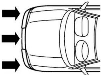
Seating and Safety Restraints
The airbags inflate and deflate rapidly upon activation. After airbag deployment, it is normal to notice a smoke-like, powdery residue or smell the burnt propellant. This may consist of cornstarch, talcum powder or sodium compounds which may irritate the skin and eyes, but none of the residue is toxic.
While the SRS is designed to help reduce serious injuries, contact with a deploying airbag may also cause abrasions, swelling or temporary hearing loss. Because airbags must inflate rapidly and with considerable force, there is the risk of death or serious injuries such as fractures, facial and eye injuries or internal injuries, particularly to occupants who are not properly restrained or are otherwise out of position at the time of airbag deployment. It is extremely important that occupants be properly restrained as far away from the airbag module as possible while maintaining vehicle control.
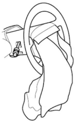
The SRS consists of:
- driver and passenger airbag modules (which include the inflators and airbags).
- seat-mounted side airbags. Refer to Seat-mounted side airbag system later in this chapter
- Safety Canopy ™ system. Refer to Safety Canopy ™ system later in this chapter.
- one or more impact and safing sensors.
• Safety belt pretensioners
• a readiness light and tone. - diagnostic module.
• and the electrical wiring which connects the components. - Front passenger sensing system. Refer to Frontpassengersensing system, later in this chapter.
- "Passenger airbag off" or "pass airbag off" indicator lamp. Refer to Frontpassengersensingsystemlater in this chapter.
Seating and Safety Restraints
The RCM (restraints control module) monitors its own internal circuits and the supplemental airbag electrical system wiring (including the impact sensors, the system wiring, the airbag system readiness light, the airbag back up power and the airbag ignitors).

Several air bag system components get hot after inflation. Do not touch them after inflation.

If the airbag has deployed, theairbagwillnotfunctionagain andmustbereplacedimmediately.If the airbag is not
replaced, the unrepaired area will increase the risk of injury in a collision.
Front passenger sensing system
The front passenger sensing system is designed to meet the regulatory requirements of Federal Motor Vehicle Safety Standard (FMVSS) 208 and is designed to disable (will not inflate) the front passenger's frontal airbag under certain conditions.
The front passenger sensing system works with sensors that are part of the front passenger's seat and safety belt. The sensors are designed to detect the presence of a properly seated occupant and determine if the front passenger's frontal airbag should be enabled (may inflate) or disabled (will not inflate).
The front passenger sensing system will disable (will not inflate) the front passenger's frontal airbag if:
- the front passenger seat is unoccupied, or has small/medium objects in the front seat,
- the system determines that an infant is present in a rear-facing infant seat that is installed according to the manufacturer's instructions,
- the system determines that a small child is present in a forward-facing child restraint that is installed according to the manufacturer's instructions,
- the system determines that a small child is present in a booster seat,
- a front passenger takes his/her weight off of the seat for a period of time,
The front passenger sensing system will turn off the passenger seat side airbag if:
- the seat is empty and safety belt is unbuckled.
Seating and Safety Restraints
The front passenger sensing system uses a "passenger airbag off" or
"pass airbag off" indicator which will illuminate and stay lit to remind you
that the front passenger frontal airbag is off. The indicator lamp is located in the center stack of the instrument panel just above the air vents.
PASSENGER AIRBAG OFF
Note: The indicator lamp will illuminate for a short period of time when the ignition is turned to the ON position to confirm it is functional.
When the front passenger seat is not occupied (empty seat) or in the event that the front passenger frontal airbag is enabled (may inflate), the indicator lamp will be unlit.
The front passenger sensing system is designed to disable (will not inflate) the front passenger's frontal airbag when a rear facing infant seat, a forward-facing child restraint, or a booster seat is detected.
- When the front passenger sensing system disables (will not inflate) the front passenger frontal airbag, the indicator lamp will illuminate and stay lit to remind you that the front passenger frontal airbag is disabled.
- If the child restraint has been installed and the indicator lamp is not lit, then turn the vehicle off, remove the child restraint from the vehicle and reinstall the restraint following the child restraint manufacturer's instructions.
The front passenger sensing system is designed to enable (may inflate) the front passenger's frontal airbag anytime the system senses that a person of adult size is sitting properly in the front passenger seat.
- When the front passenger sensing system enables the front passenger frontal airbag (may inflate), the indicator will be unlit and stay unlit.
If a person of adult size is sitting in the front passenger's seat, but the "passenger airbag off" or "pass airbag off" indicator lamp is lit, it is possible that the person isn't sitting properly in the seat. If this happens:
- Turn the vehicle off and ask the person to place the seatback in the full upright position.
- Have the person sit upright in the seat, centered on the seat cushion, with the person's legs comfortably extended.
- Restart the vehicle and have the person remain in this position for about two minutes. This will allow the system to detect that person and enable the passenger's frontal airbag.
Seating and Safety Restraints
- If the indicator lamp remains lit even after this, the person should be advised to ride in the rear seat.
| Occupant | PassAirbagOff IndicatorLamp | PassengerAirbag |
| Empty seat Unlit Disabled | ||
| Small child in child safety seat or booster | Lit Disabled | |
| Small child with safety belt buckled or unbuckled | Lit Disabled | |
| Adult Unlit Enabled |

Even with Advanced Restraints Systems, children 12 and under should be properly restrained in the back seat.
After all occupants have adjusted their seats and put on safety belts, it's very important that they continue to sit properly. A properly seated occupant sits upright, leaning against the seat back, and centered on the seat cushion, with their feet comfortably extended on the floor. Sitting improperly can increase the chance of injury in a crash event. For example, if an occupant slouches, lies down, turns sideways, sits forward, leans forward or sideways, or puts one or both feet up, the chance of injury during a crash is greatly increased.

Sitting improperly out of position or with the seat back reclined too far can take off weight from the seat cushion and affect the on of the front passenger sensing system, resulting in serious or death in a crash.
Always sit upright against your seatback, with your feet on the floor.
Seating and Safety Restraints
The front passenger sensing system may detect small or medium objects placed on the seat cushion. For most objects that are in the front passenger seat, the passenger airbag will be disabled. Even though the passenger airbag is disabled, the "pass airbag off" lamp may or may not be illuminated according to the table below.
| Objects | PassAirbagOff IndicatorLamp | PassengerAirbag |
| Small (i.e. 3 ring binder, small purse, bottled water) | Unlit Disabled | |
| Medium (i.e. heavy briefcase, fully packed luggage) | Lit Disabled | |
| Empty seat, or small to medium object with safety belt buckled | Lit Disabled |
If you think that the status of the passenger airbag off indicator lamp is incorrect, check for the following:
- Objects lodged underneath the seat
- Objects between the seat cushion and the center console (if equipped)
- Objects hanging off the seat back
- Objects stowed in the seatback map pocket (if equipped)
- Objects placed on the occupant's lap
• Cargo interference with the seat - Other passengers pushing or pulling on the seat
- Rear passenger feet and knees resting or pushing on the seat
The conditions listed above may cause the weight of a properly seated occupant to be incorrectly interpreted by the front passenger sensing system. The person in the front passenger seat may appear heavier or lighter due to the conditions described in the list above.
Seating and Safety Restraints

To reduce the risk of possible serious injury:
Do not stow objects in seat back map pocket (if equipped) or objects off seat back if a child is in the front passenger seat.
Do not place objects underneath the front passenger seat or between the seat and the center console (if equipped).
Check the "passenger airbag off" or "pass airbag off" indicator lamp for proper airbag Status.
Failure to follow these instructions may interfere with the front passenger seat sensing system.
In case there is a problem with the front passenger sensing system, the airbag readiness lamp in the instrument cluster will stay lit.

If the airbagreadinesslampislit, do the following:
The driver and/or adult passengers should check for any objects that may be lodged underneath the front passenger seat or cargo interfering with the seat.
If objects are lodged and/or cargo is interfering with the seat; please take the following steps to remove the obstruction:
- Pull the vehicle over.
- Turn the vehicle off.
- Driver and/or adult passengers should check for any objects lodged underneath the front passenger seat or cargo interfering with the seat.
- Remove the obstruction(s) (if found).
- Restart the vehicle.
- Wait at least 2 minutes and verify that the airbag readiness lamp is no longer illuminated
- If the airbag readiness lamp remains illuminated, this may or may/not be a problem due to the front passenger sensing system.
DO NOT attempt to repair or service the system; take your vehicle immediately to an authorized dealer.
If it is necessary to modify an advanced front airbag system to accommodate a person with disabilities, contact the Ford Customer Relationship Center at the phone number shown in the Customer Assistance chapter of this Owner's Guide.
Seating and Safety Restraints

Any alteration/modification to the front passenger seat may affect the performance of the front passenger sensing system.
Determining if the system is operational
The SRS uses a readiness light in the instrument cluster or a tone to indicate the status of the system. Refer to Airbagreadinesssection in the InstrumentClusterchapter. Routine maintenance of the airbag is not required.
A difficulty with the system is indicated by one or more of the following:
• The readiness light will either flash or stay lit.
• The readiness light will not illuminate immediately after ignition is turned on.
- A series of five beeps will be heard. The tone pattern will repeat periodically until the problem and/or light are repaired.
If any of these things happen, even intermittently, have the SRS serviced at an authorized dealer immediately. Unless serviced, the system may not function properly in the event of a collision.

Seat-mounted side airbag system

Do not place objects or mount equipment on or near the airbag cover on the side of the seatbacks of the front seats or in front seat areas that may come into contact with a deploying airbag. Failure to follow these instructions may increase the risk of personal injury in the event of a collision.
Do not use accessory seat covers. The use of accessory seat covers may prevent the deployment of the side airbags and increase the risk of injury in an accident.
Do not lean your head on the door. The side airbag could injure you as it deploys from the side of the seatback.
Seating and Safety Restraints

Do not attempt to service, repair, or modify the airbag SRS, its fuses or the seat cover on a seat containing an airbag. See an rized dealer.

All occupants of the vehicle should always wear their safety belts even when an airbag SRS is provided.
Howdoesthesideairbagsystemwork?
The design and development of the side airbag system included recommended testing procedures that were developed by a group of automotive safety experts known as the Side Airbag Technical Working Group. These recommended testing procedures help reduce the risk of injuries related to the deployment of side airbags.
The side airbag system consists of the following:
- An inflatable nylon bag (airbag) with a gas generator concealed behind the outboard bolster of the driver and front passenger seatbacks.

- A special seat cover designed to allow airbag deployment.
- The same warning light, electronic control and diagnostic unit as used for the front airbags.
- Two crash sensors located on the lower portion of the b-pillar (one on each side of the vehicle).
Side airbags, in combination with safety belts, can help reduce the risk of severe injuries in the event of a significant side impact collision.
The side airbags are fitted on the outboard side of the seatbacks of the front seats. In certain lateral collisions, the airbag on the side affected by the collision will be inflated. If the front passenger sensing system detects an empty seat, the front passenger seat-mounted side airbag will be deactivated. The airbag was designed to inflate between the door panel and occupant to further enhance the protection provided occupants in side impact collisions.
Seating and Safety Restraints
The airbag SRS is designed to activate when the vehicle sustains lateral deceleration sufficient to cause the sensors to close an electrical circuit that initiates airbag inflation.
The fact that the airbags did not inflate in a collision does not mean that something is wrong with the system. Rather, it means the forces were not of the type sufficient to cause activation. Side airbags are designed to inflate in side-impact collisions, not roll-over, rear-impact, frontal or near-frontal collisions, unless the collision causes sufficient lateral deceleration.

Several airbag system components get hot after inflation. Do not touch them after inflation.

If the side airbag has deployed, theairbagwill
notfunctionagain. Theside airbagsystem(includingthe seat)mustbeinspectedand servicedbyanauthorized dealer. If the airbag is not replaced, the unrepaired area will increase the risk of injury in a collision.
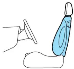
Determiningifthesystemisoperational
The SRS uses a readiness light in the instrument cluster or a tone to indicate the condition of the system. Refer to the Airbagreadiness section in the InstrumentClusterchapter. Routine maintenance of the side airbag is not required.
A difficulty with the system is indicated by one or more of the following:
- The readiness light (same light as for front airbag system) will either flash or stay lit.
- The readiness light will not illuminate immediately after ignition is turned on.
- A series of five beeps will be heard. The tone pattern will repeat periodically until the problem and/or light are repaired.
If any of these things happen, even intermittently, have the SRS serviced at your authorized dealer immediately. Unless serviced, the system may not function properly in the event of a collision.
Seating and Safety Restraints
Safety Canopy ™ system

Do not place objects or mount equipment on or near the headliner at the siderail that may come into contact with a deploying Safety Canopy ™ . Failure to follow these instructions may increase the risk of personal injury in the event of a collision.


Do not lean your head on the door. The Safety Canopy ™ could injure you as it deploys from the headliner.

Do not attempt to service, repair, or modify the Safety Canopy ™ system, its fuses, the A, B, or C pillar trim, or the headliner on a e containing a Safety Canopy ™ . See your authorized dealer.

All occupants of the vehicle including the driver should always wear their safety belts even when an airbag SRS and Safety system is provided.

To reduce risk of injury, do not obstruct or place objects in the deployment path of the inflatable Safety Canopy ™ .
Seating and Safety Restraints
HowdoestheSafetyCanopy®systemwork?
The design and development of the Safety Canopy ™ system included recommended testing procedures that were developed by a group of automotive safety experts known as the Side Airbag Technical Working Group. These recommended testing procedures help reduce the risk of injuries related to the deployment of side airbags (including the Safety Canopy ™ ).
The Safety Canopy® system consists of the following:
- An inflatable nylon curtain with a gas generator concealed behind the headliner and above the doors (one on each side of vehicle).
- A headliner designed to flex open above the side doors to allow Safety Canopy® deployment.
- The same warning light, electronic control and diagnostic unit as used for the front airbags.
- Two crash sensors mounted at lower B-Pillar (one on each side).
- Two crash sensors located at the c-pillar behind the rear doors (one on each side).
- Rollover sensor in the restraints control module (RCM).
The Safety Canopy ® system, in combination with safety belts, can help reduce the risk of severe injuries in the event of a significant side impact collision or rollover event.
Children 12 years old and under should always be properly restrained in the second or third row seats. The Safety Canopy TM will not interfere with children restrained using a properly installed child or booster seat because it is designed to inflate downward from the headliner above the doors along the side window opening.
The Safety Canopy ® system is designed to active when the vehicle sustains lateral deceleration sufficient to cause the RCM to initiate Safety Canopy ® inflation or when a certain likelihood of a rollover event is detected by the rollover sensor.

Seating and Safety Restraints
The Safety Canopy ® is mounted to roof side-rail sheet metal, behind the headliner, above the first and second row seats. The Safety Canopy ® is designed to inflate between the side window area and occupants to further enhance protection provided in side impact collisions and rollover events.
The fact that the Safety Canopy 150 did not activate in a collision does not mean that something is wrong with the system. Rather, it means the forces were not of the type sufficient to cause activation. The Safety Canopy 129 is designed to inflate in certain side impact collisions or rollover events, not in rear impact, frontal or near-frontal collisions, unless the collision causes sufficient lateral deceleration or rollover likelihood.

Several Safety Canopy ™
after inflation. Do not touch them after inflation.


If the Safety Canopy ™
system has deployed, the
SafetyCanopy ™ will not function again unless replaced.
The Safety Canopy ™ system (including the A, Band C
pillartrim)mustbeinspected andservicedbyaauthorized
dealer. If the Safety Canopy 128 is not replaced, the unrepaired area will increase the risk of injury in a collision.
Seating and Safety Restraints
Determiningifthesystemisoperational
The SRS uses a readiness light in the instrument cluster or a tone to indicate the condition of the system. Refer to the Airbagreadiness section in the InstrumentClusterchapter. Routine maintenance of the side airbag is not required.
A difficulty with the system is indicated by one or more of the following:
- The readiness light (same light as for front airbag system) will either flash or stay lit.
- The readiness light will not illuminate immediately after ignition is turned on.
- A series of five beeps will be heard. The tone pattern will repeat periodically until the problem and/or light are repaired.
If any of these things happen, even intermittently, have the SRS serviced at your authorized dealer immediately. Unless serviced, the system may not function properly in the event of a collision.
Disposal of airbags and airbag equipped vehicles (including pretensioners)
See your authorized dealer. Airbags MUST BE disposed of by qualified personnel.
SAFETY RESTRAINTS FOR CHILDREN
See the following sections for directions on how to properly use safety restraints for children. Also see Airbagsupplementalrestraintsystem (SRS) in this chapter for special instructions about using airbags.
Important child restraint precautions
You are required by law to use safety restraints for children in the U.S. and Canada. If small children (generally children who are four years old or younger and who weigh 40 lb. [18 kg] or less) ride in your vehicle, you must put them in safety seats made especially for children. Many states require that children use approved booster seats until they are eight years old. Check your local and state or provincial laws for specific requirements regarding the safety of children in your vehicle. When possible, always place children under age 12 in the rear seat of your vehicle. Accident statistics suggest that children are safer when properly restrained in the rear seating positions than in the front seating position.
Seating and Safety Restraints

Never let a passenger hold a child on his or her lap while the vehicle is moving. The passenger cannot protect the child from in a collision.
Always follow the instructions and warnings that come with any infant or child restraint you might use.
Children and safety belts
If the child is the proper size, restrain the child in a safety seat. Children who are too large for child safety seats (as specified by your child safety seat manufacturer) should always wear safety belts.
Follow all the important safety restraint and airbag precautions that apply to adult passengers in your vehicle.
If the shoulder belt portion of a combination lap and shoulder belt can be positioned so it does not cross or rest in front of the child's face or neck, the child should wear the lap and shoulder belt. Moving the child closer to the center of the vehicle may help provide a good shoulder belt fit.

Do not leave children, unreliable adults, or pets unattended in your vehicle.
Child booster seats
Children outgrow a typical convertible or toddler seat when they weigh 40 lb. (18 kg) and are around 4 years of age. Although the lap/shoulder belt will provide some protection, these children are still too small for lap/shoulder belts to fit properly, which could increase the risk of serious injury in a crash.
To improve the fit of both the lap and shoulder belt on children who have outgrown child safety seats, Ford Motor Company recommends use of a belt-positioning booster.
Booster seats position a child so that safety belts fit better. They lift the child up so that the lap belt rests low across the hips and the knees bend comfortably. Booster seats may also make the shoulder belt fit better and more comfortably. Try to keep the belt near the middle of the shoulder.
Seating and Safety Restraints
Whenchildrenshoulduseboosterseats
Children need to use booster seats from the time they outgrow the toddler seat until they are big enough for the vehicle seat and lap/shoulder belt to fit properly. Generally this is when they weigh about 80 lb. (36 kg) (about 8 to 12 years old).
Booster seats should be used until you can answer YES to ALL of these questions:
- Can the child sit all the way back against the vehicle seat back with knees bent comfortably at the edge of the seat without slouching?
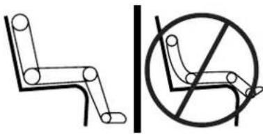
- Does the lap belt rest low across the hips?
- Is the shoulder belt centered on the shoulder and chest?
- Can the child stay seated like this for the whole trip?
Typesofboosterseats
There are two types of belt-positioning booster seats:
• Those that are backless.
If your backless booster seat has a removable shield, remove the shield and use the lap/shoulder belt. If a seating position has a low seat back and no head restraint, a backless booster seat may place your child's head (top of car level) above the top of the seat. In this case, move the backless booster to another

scating position with a higher seat back and lap/shoulder belts.
Seating and Safety Restraints
• Those with a high back.
If, with a backless booster seat, you cannot find a seating position that adequately supports your child's head, a high back booster seat would be a better choice.

Either type can be used at any seating position equipped with lap/shoulder belts if your child is over 40 lb. (18 kg).
Children and booster seats vary widely in size and shape. Choose a booster that keeps the lap belt low and snug across the hips, never up across the stomach, and lets you adjust the shoulder belt to cross the chest and rest snugly near the center of the shoulder. The drawings below compare the ideal fit (center) to a shoulder belt uncomfortably close to the neck and a shoulder belt that could slip off the shoulder.

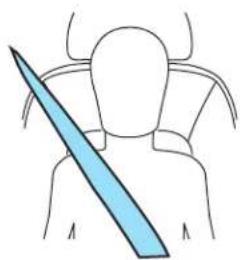

If the booster seat slides on the vehicle seat, placing a rubberized mesh sold as shelf or carpet liner under the booster seat may improve this condition.
Theimportanceofshoulderbelts
Using a booster without a shoulder belt increases the risk of a child's head hitting a hard surface in a collision. For this reason, you should never use a booster seat with a lap belt only. It is best to use a booster seat with lap/shoulder belts in the back seat- the safest place for children to ride.
Seating and Safety Restraints

Move a child to a different seating location if the shoulder belt does not stay positioned on the shoulder during use.

Follow all instructions provided by the manufacturer of the booster seat.

Never put the shoulder belt under a child's arm or behind the back because it eliminates the protection for the upper part of body and may increase the risk of injury or death in a collision.

Never use pillows, books, or towels to boost a child. They can slide around and increase the likelihood of injury or death in a on.
SAFETY SEATS FOR CHILDREN
Child and infant or child safety seats
Use a safety seat that is recommended for the size and weight of the child. Carefully follow all of the manufacturer's instructions with the safety seat you put in your vehicle. If you do not install and use the safety seat properly, the child may be injured in a sudden stop or collision.
When installing a child safety seat:
- Review and follow the information presented in the airbag supplementalrestraintsystem (SRS) section in this chapter.
- Use the correct safety belt buckle for that seating position (the buckle closest to the direction the tongue is coming from).
- Insert the belt tongue into the proper buckle until you hear a snap and feel it latch. Make sure the tongue is securely fastened in the buckle.
- Keep the buckle release button pointing up and away from the safety seat, with the tongue between the child seat and the release button, to prevent accidental unbuckling.
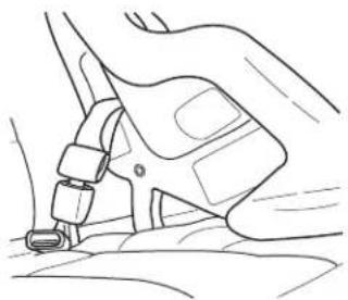
Seating and Safety Restraints
- Place seat back in upright position.
- Put the safety belt in the automatic locking mode. Refer to Automatic lockingmode(passengersidefrontandoutboardrearseating positions)(ifequipped)section in this chapter.
- LATCH lower anchors are recommended for use by children up to 48 lb. (22 kg) in a child restraint. Top tether anchors can be used for children up to 60 lb. (27 kg) in a child restraint, and to provide upper torso restraint for children up to 80 lb. (36 kg) using an upper torso harness and a belt-positioning booster.
Ford recommends the use of a child safety seat having a top tether strap. Install the child safety seat in a seating position with LATCH and tether anchors. For more information on top tether straps and anchors, refer to Attachingsafetyseatswithtetherstrapsin this chapter. For more information of LATCH anchors refer to Attachingsafetyseatswith LATCH(LowerAnchorsandTethersforChildren)attachmentsin this chapter.

Carefully follow all of the manufacturer's instructions included with the safety seat you put in your vehicle. If you do not install use the safety seat properly, the child may be injured in a sudden or collision.

Rear-facing child seats or infant carriers should never be placed in front of an active passenger airbag.
Installing child safety seats with combination lap and shoulder belts
Therearseatheadrestraintsmustberemovedwhenusingachild seat.

Airbags can kill or injure a child in a child seat. NEVERplace a rear-facing child seat in front of an active air bag. If you must forward-facing child seat in the front seat, move the seat all the ack.
Seating and Safety Restraints
- Position the child safety seat in a seat with a combination lap and shoulder belt.
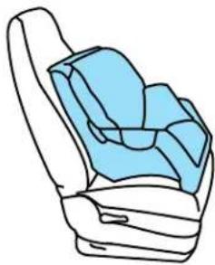

Children 12 and under should be properly restrained in the rear seat whenever possible.
- Pull down on the shoulder belt and then grasp the shoulder belt and lap belt together.
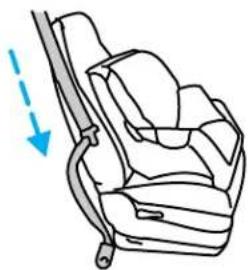
- While holding the shoulder and lap belt portions together, route the tongue through the child seat according to the child seat manufacturer's instructions. Be sure the belt webbing is not twisted.
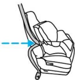
Seating and Safety Restraints
- Insert the belt tongue into the proper buckle (the buckle closest to the direction the tongue is coming from) for that seating position until you hear a snap and feel the latch engage. Make sure the tongue is latched securely by pulling on it.

- To put the retractor in the automatic locking mode, grasp the shoulder portion of the belt and pull downward until all of the belt is extracted and a click is heard.
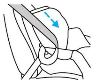
-
Allow the belt to retract. The belt will click as it retracts to indicate it is in the automatic locking mode.
-
Pull the lap belt portion across the child seat toward the buckle and pull up on the shoulder belt while pushing down with your knee on the child seat.

Seating and Safety Restraints
-
Allow the safety belt to retract to remove any slack in the belt.
-
Before placing the child in the seat, forcibly tilt the seat forward and back to make sure the seat is securely held in place. To check this, grab the seat at the belt path and attempt to move it side to side and forward and back. There should be no more than one inch of movement for proper installation.
-
Try to pull the belt out of the retractor to make sure the retractor is in the automatic locking mode (you should not be able to pull more belt out). If the retractor is not locked, unbuckle the belt and repeat Steps 2 through 9.
Check to make sure the child seat is properly secured before each use.

Attaching child safety seats with tether straps
Most new forward-facing child safety seats include a tether strap which goes over the back of the seat and hooks to an anchoring point. Tether straps are available as an accessory for many older safety seats. Contact the manufacturer of your child seat for information about ordering a tether strap.
The rear seating positions of your vehicle are equipped with built-in tether strap anchors located behind the seats on the roof panel in the cargo area.
The tether strap anchors in your vehicle are in the following positions:
Attach the tether strap only to the appropriate tether anchor as shown. The tether strap may not work properly if attached somewhere other than the correct tether anchor.

- Position the child safety seat on the seat cushion.
- Route the child safety seat tether strap over the back of the seat. For vehicles with adjustable head restraints, remove the head restraint first, place under the front seat for storage, and then route the tether strap over the top of the seatback.
Seating and Safety Restraints
- Locate the correct anchor for the selected seating position.
There are three tether anchors located on the headliner at the rear of the vehicle.

- Clip the tether strap to the anchor as shown.
The arrow in the above graphic points toward the front of the vehicle.

If the tether strap is clipped incorrectly, the child safety seat may not be retained properly in the event of a collision.

-
Install the child safety seat tightly using the LATCH anchors or safety belts. Follow the instructions in this chapter.
-
Tighten the child safety seat tether strap according to the manufacturer's instructions.
If the safety seat is not anchored properly, the risk of a child being injured in a collision greatly increases.
Seating and Safety Restraints
Attaching safety seats with LATCH (Lower Anchors and Tethers for Children) attachments for child seat anchors
Some child safety seats have two rigid or webbing mounted attachments that connect to two anchors at certain seating positions in your vehicle. This type of child seat eliminates the need to use safety belts to attach the child seat. For forward-facing child seats, the tether strap must also be attached to the proper tether anchor. See Attachingsafetyseatswith tetherstrapsin this chapter.
Your vehicle has LATCH anchors for child seat installation at the following locations:
The anchors on both sides of the center of the rear seat are provided primarily for child seats at the outboard seats, and are further apart than the pairs of lower anchors for child seat installation at other seats. A child seat with rigid LATCH attachments cannot be installed at the center rear seat. A child seat with LATCH attachments on belt webbing can be used at the center rear seat unless a child seat at an outboard rear seat is attached to one of these lower anchors. Install a child seat onto the lower anchors at the center rear seat ONLY IF the child restraint manufacturer recommends that the child seat can be installed to anchors that are spaced up to 20 in (500 mm) apart.

Never attach two LATCH child safety seats to the same anchor. In a crash, one anchor may not be strong enough to hold two child safety seat attachments and may break, causing serious injury or death.
Seating and Safety Restraints
The lower anchors for child seat installation are located at the rear section of the second row seat between the cushion and seat back.

Follow the child seat manufacturer's instructions to properly install a child seat with LATCH attachments.

Attach LATCH lower attachments of the child seat only to the anchors shown.
If you install a child seat with rigid LATCH attachments, do not tighten the tether strap enough to lift the child seat off the vehicle seat cushion when the child is seated in it. Keep the tether strap just snug without lifting the front of the child seat. Keeping the child seat just touching the vehicle seat gives the best protection in a severe crash.
Each time you use the safety seat, check that the seat is properly attached to the lower anchors and tether anchor. Try to tilt the child seat from side to side. Also try to tug the seat forward. Check to see if the anchors hold the seat in place.

If the safety seat is not anchored properly, the risk of a child being injured in a crash greatly increases.
Tires, Wheels and Loading
NOTICE TO UTILITY VEHICLE AND TRUCK OWNERS
Utility vehicles and trucks handle differently than passenger cars in the various driving conditions that are encountered on streets, highways and off-road. Utility vehicles and trucks are not designed for cornering at speeds as high as passenger cars any more than low-slung sports cars are designed to perform satisfactorily under off-road conditions.

Utility vehicles have a significantly higher rollover rate than other types of vehicles. To reduce the risk of serious injury or death from a rollover or other crash you must:
- Avoid sharp turns and abrupt maneuvers;
- Drive at safe speeds for the conditions;
- Keep tires properly inflated;
- Never overload or improperly load your vehicle; and
- Make sure every passenger is properly restrained.
In a rollover crash, an unbelted person is significantly more likely to die than a person wearing a seat belt. All occupants must wear seat belts and children/infants must use appropriate restraints to minimize the risk of injury or ejection.
Study your "Owner's Guide" and any supplements for specific information about equipment features, instructions for safe driving and additional precautions to reduce the risk of an accident or serious injury.
VEHICLE CHARACTERISTICS
4WD and AWD Systems
A vehicle equipped with AWD or 4WD has the ability to use all four wheels to power itself. This increases traction which may enable you to safely drive over terrain and road conditions that a conventional two-wheel drive vehicle cannot.
Tires, Wheels and Loading
Power is supplied to all four wheels through a transfer case or power transfer unit. You should become thoroughly familiar with this information before you operate your vehicle.
Do not become overconfident in the ability of 4WD and AWD vehicles. Although a 4WD or AWD vehicle may accelerate better than two-wheel drive vehicle in low traction situations, it won't stop any faster than two-wheel drive vehicles. Always drive at a safe speed.
How your vehicle differs from other vehicles
SUV and trucks can differ from some other vehicles in a few noticeable ways. Your vehicle may be:
- Higher – to allow higher load carrying capacity and to allow it to travel over rough terrain without getting hung up or damaging underbody components.
- Shorter – to give it the capability to approach inclines and drive over the crest of a hill without getting hung up or damaging underbody components. All other things held equal, a shorter wheelbase may make your vehicle quicker to respond to steering inputs than a vehicle with a longer wheelbase.
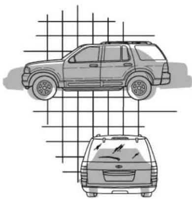
Tires, Wheels and Loading
- Narrower — to provide greater maneuverability in tight spaces, particularly in off-road use.
As a result of the above dimensional differences, SUV's and trucks often will have a higher center of gravity and a greater difference in center of gravity between the loaded and unloaded condition.
These differences that make your vehicle so versatile also make it handle differently than an ordinary passenger car.
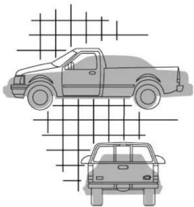
INFORMATION ABOUT UNIFORM TIRE QUALITY GRADING
New vehicles are fitted with tires that have a rating on them called Tire Quality Grades. The Quality grades can be found where applicable on the tire sidewall between tread shoulder and maximum section width. For example:

•Treadwear200TractionAATemperatureA
These Tire Quality Grades are determined by standards that the United States Department of Transportation has set.
Tire Quality Grades apply to new pneumatic tires for use on passenger cars. They do not apply to deep tread, winter-type snow tires, space-saver or temporary use spare tires, tires with nominal rim diameters of 10 to 12 inches or limited production tires as defined in Title 49 Code of Federal Regulations Part 575.104(c)(2).
U.S.DepartmentofTransportation-Tirequalitygrades:The U.S. Department of Transportation requires Ford Motor Company to give you the following information about tire grades exactly as the government has written it.
Treadwear
The treadwear grade is a comparative rating based on the wear rate of the tire when tested under controlled conditions on a specified
Tires, Wheels and Loading
government test course. For example, a tire graded 150 would wear one and one-half (1 1/2) times as well on the government course as a tire graded 100. The relative performance of tires depends upon the actual conditions of their use, however, and may depart significantly from the norm due to variations in driving habits, service practices, and differences in road characteristics and climate.
Traction AA A B C
The traction grades, from highest to lowest are AA, A, B, and C. The grades represent the tire's ability to stop on wet pavement as measured under controlled conditions on specified government test surfaces of asphalt and concrete. A tire marked C may have poor traction performance.

The traction grade assigned to this tire is based on straight-ahead braking traction tests, and does not include eration, cornering, hydroplaning or peak traction characteristics.
Temperature A B C
The temperature grades are A (the highest), B and C, representing the tire's resistance to the generation of heat and its ability to dissipate heat when tested under controlled conditions on a specified indoor laboratory test wheel. Sustained high temperature can cause the material of the tire to degenerate and reduce tire life, and excessive temperature can lead to sudden tire failure. The grade C corresponds to a level of performance which all passenger car tires must meet under the Federal Motor Vehicle Safety Standard No. 109. Grades B and A represent higher levels of performance on the laboratory test wheel than the minimum required by law.

The temperature grade for this tire is established for a tire that is properly inflated and not overloaded. Excessive speed, inflation, or excessive loading, either separately or in nation, can cause heat buildup and possible tire failure.
TIRES
Tires are designed to give many thousands of miles of service, but they must be maintained in order to get the maximum benefit from them.
Glossary of tire terminology
- Tire label: A label showing the OE (Original Equipment) tire sizes, recommended inflation pressure and the maximum weight the vehicle can carry.
Tires, Wheels and Loading
- TireIdentificationNumber(TIN): A number on the sidewall of each tire providing information about the tire brand and manufacturing plant, tire size and date of manufacture. Also referred to as DOT code.
- Inflationpressure:A measure of the amount of air in a tire.
- Standard load: A class of P-metric or Metric tires designed to carry a maximum load at 35 psi [37 psi (2.5 bar) for Metric tires]. Increasing the inflation pressure beyond this pressure will not increase the tire's load carrying capability.
- Extra load: A class of P-metric or Metric tires designed to carry a heavier maximum load at 41 psi [43 psi (2.9 bar) for Metric tires]. Increasing the inflation pressure beyond this pressure will not increase the tire's load carrying capability.
- kPa:Kilopascal, a metric unit of air pressure.
- PSI: Pounds per square inch, a standard unit of air pressure.
- Coldinflationpressure:The tire pressure when the vehicle has been stationary and out of direct sunlight for an hour or more and prior to the vehicle being driven for 1 mile (1.6 km).
- Recommended inflation pressure: The cold inflation pressure found on the Safety Compliance Certification Label or Tire Label located on the B-Pillar or the edge of the driver's door.
- B-pillar: The structural member at the side of the vehicle behind the front door.
- Beadareaofthetire: Area of the tire next to the rim.
- Sidewallofthetire: Area between the bead area and the tread.
- Treadareaofthetire: Area of the perimeter of the tire that contacts the road when mounted on the vehicle.
- Rim: The metal support (wheel) for a tire or a tire and tube assembly upon which the tire beads are seated.
INFLATING YOUR TIRES
Safe operation of your vehicle requires that your tires are properly inflated. Remember that a tire can lose up to half of its air pressure without appearing flat.
Every day before you drive, check your tires. If one looks lower than the others, use a tire gauge to check pressure of all tires and adjust if required.
Tires, Wheels and Loading
At least once a month and before long trips, inspect each tire and check the tire pressure with a tire gauge (including spare, if equipped). Inflate all tires to the inflation pressure recommended by Ford Motor Company.
Use a tire gauge to check the tire inflation pressure, including the spare (if equipped), at least monthly and before long trips. You are strongly urged to buy a reliable tire pressure gauge, as automatic service station gauges may be inaccurate. Ford recommends the use of a digital or dial-type tire pressure gauge rather than a stick-type tire pressure gauge.
Use the recommended cold inflation pressure for optimum tire performance and wear. Under-inflation or over-inflation may cause uneven treadwear patterns.
Under-inflation is the most common cause of tire failures and may result in severe tire cracking, tread separation or "blowout", with unexpected loss of vehicle control and increased risk of injury. Under-inflation increases sidewall flexing and rolling resistance, resulting in heat buildup and internal damage to the tire. It also may result in unnecessary tire stress, irregular wear, loss of vehicle control and accidents. A tire can lose up to half of its air pressure and not appear to be flat!
Always inflate your tires to the Ford recommended inflation pressure even if it is less than the maximum inflation pressure information found on the tire. The Ford recommended tire inflation pressure is found on the Safety Compliance Certification Label or Tire Label which is located on the B-Pillar or the edge of the driver's door. Failure to follow the tire pressure recommendations can cause uneven treadwear patterns and adversely affect the way your vehicle handles.
MaximumPermissibleInflationPressureis the tire manufacturer's maximum permissible pressure and/or the pressure at which the maximum load can be carried by the tire. This pressure is normally higher than the manufacturer's recommended cold inflation pressure which can be found on the Safety Compliance Certification Label or Tire Label which is located on the B-Pillar or the edge of the driver's door. The cold inflation pressure should never be set lower than the recommended pressure on the Safety Compliance Certification Label or Tire Label.
When weather temperature changes occur, tire inflation pressures also change. A 10° F ( 6° C) temperature drop can cause a corresponding drop of 1 psi (7 kPa) in inflation pressure. Check your tire pressures frequently and adjust them to the proper pressure which can be found on the Safety Compliance Certification Label or Tire Label.
Tires, Wheels and Loading
To check the pressure in your tire(s):
- Make sure the tires are cool, meaning they are not hot from driving even a mile.
If you are checking tire pressure when the tire is hot, (i.e. driven more than 1 mile [1.6 km]), never “bleed” or reduce air pressure. The tires are hot from driving and it is normal for pressures to increase above recommended cold pressures. A hot tire at or below recommended cold inflation pressure could be significantly under-inflated.
Note: If you have to drive a distance to get air for your tire(s), check and record the tire pressure first and add the appropriate air pressure when you get to the pump. It is normal for tires to heat up and the air pressure inside to go up as you drive.
-
Remove the cap from the valve on one tire, then firmly press the tire gauge onto the valve and measure the pressure.
-
Add enough air to reach the recommended air pressure.
Note: If you overfill the tire, release air by pushing on the metal stem in the center of the valve. Then recheck the pressure with your tire gauge.
-
Replace the valve cap.
-
Repeat this procedure for each tire, including the spare.
Note: Some spare tires operate at a higher inflation pressure than the other tires. For T-type/mini-spare tires (see DissimilarSpare Tire/WheelInformationsection for description): Store and maintain at 60psi (4.15 bar). For Full Size and Dissimilar spare tires (see Dissimilar SpareTire/WheelInformationsection for description): Store and maintain at the higher of the front and rear inflation pressure as shown on the Tire Label.
-
Visually inspect the tires to make sure there are no nails or other objects embedded that could poke a hole in the tire and cause an air leak.
-
Check the sidewalls to make sure there are no gouges, cuts or bulges.
TIRE CARE
Inspecting your tires
Periodically inspect the tire treads for uneven or excessive wear and remove objects such as stones, nails or glass that may be wedged in the tread grooves. Check for holes or cuts that may permit air leakage from the tire and make necessary repairs. Also inspect the tire sidewalls for
Tires, Wheels and Loading
cracking, cuts, bruises and other signs of damage or excessive wear. If internal damage to the tire is suspected, have the tire demounted and inspected in case it needs to be repaired or replaced. For your safety, tires that are damaged or show signs of excessive wear should not be used because they are more likely to blow out or fail.
Improper or inadequate vehicle maintenance can cause tires to wear abnormally. Inspect all your tires, including the spare, frequently, and replace them if one or more of the following conditions exist:
Tire wear
When the tread is worn down to 1/16th of an inch (2 mm), tires must be replaced to help prevent your vehicle from skidding and hydroplaning. Built-in treadwear indicators, or "wear bars", which look like narrow strips of smooth rubber across the tread will appear on the tire when the tread is worn down to 1/16th of an inch (2 mm). When the tire tread wears down to the same height as these “wear bars”, the tire is worn out and must be replaced.

Damage
Periodically inspect the tire treads and sidewalls for damage (such as bulges in the tread or sidewalls, cracks in the tread groove and separation in the tread or sidewall). If damage is observed or suspected have the tire inspected by a tire professional. Tires can be damaged during off-road use, so inspection after off-road use is also recommended.

Age
Tires degrade over time depending on many factors such as weather, storage conditions, and conditions of use (load, speed, inflation pressure, etc.) the tires experience throughout their lives. In general, tires should be replaced after six years regardless of tread wear. However, heat caused by hot climates or frequent high loading conditions can accelerate the aging process and may require tires to be replaced more frequently. You should replace your spare tire when you replace the road tires or after six years due to aging even if it has not been used.
Tires, Wheels and Loading
U.S. DOT Tire Identification Number (TIN)
Both U.S. and Canada Federal regulations require tire manufacturers to place standardized information on the sidewall of all tires. This information identifies and describes the fundamental characteristics of the tire and also provides a U.S. DOT Tire Identification Number for safety standard certification and in case of a recall.
This begins with the letters "DOT" and indicates that the tire meets all federal standards. The next two numbers or letters are the plant code designating where it was manufactured, the next two are the tire size code and the last four numbers represent the week and year the tire was built. For example, the numbers 317 mean the 31st week of 1997. After 2000 the numbers go to four digits. For example, 2501 means the 25th week of 2001. The numbers in between are identification codes used for traceability. This information is used to contact customers if a tire defect requires a recall.
Tire Replacement Requirements
Your vehicle is equipped with tires designed to provide a safe ride and handling capability.
Only use replacement tires and wheels that are the same size, load index, speed rating and type (such as P-metric versus LT-metric or all-season versus all-terrain) as those originally provided by Ford. The recommended tire and wheel size may be found on either the Safety Compliance Certification Label or the Tire Label which is located on the B-Pillar or edge of the driver's door. If this information is not found on these labels then you should consult your Ford dealer. Use of any tire or wheel not recommended by Ford can affect the safety and performance of your vehicle, which could result in an increased risk of loss of vehicle control, vehicle rollover, personal injury and death. Additionally the use of non-recommended tires and wheels could cause steering, suspension, axle or transfer case/power transfer unit failure. If you have questions regarding tire replacement, see an authorized dealer.
Tires, Wheels and Loading

When mounting replacement tires and wheels, you should not exceed the maximum pressure indicated on the sidewall of the set the beads without additional precautions listed below. If the do not seat at the maximum pressure indicated, re-lubricate and again.
When inflating the tire for mounting pressures up to 20 psi greater than the maximum pressure on the tire sidewall, the following precautions must be taken to protect the person mounting the tire:
- Make sure that you have the correct tire and wheel size.
- Lubricate the tire bead and wheel bead seat area again.
-
Stand at a minimum of 12 feet away from the tire wheel assembly.
-
Use both eye and ear protection.
For a mounting pressure more than 20 psi greater than the maximum pressure, a Ford Dealer or other tire service professional should do the mounting.
Always inflate steel carcass tires with a remote air fill with the person inflating standing at a minimum of 12 ft. away from the tire wheel assembly.
It is recommended that the two front tires or two rear tires generally be replaced as a pair.
Important: Remember to replace the valve stems when the road tires are replaced on your vehicle.
Note: The use of a different tire can effect the fuel economy of your vehicle.
The tire pressure monitoring sensors mounted in the wheels (originally installed on your vehicle) are not designed to be used in aftermarket wheels.
The use of wheels or tires not recommended by Ford Motor Company may affect the operation of your Tire Pressure Monitoring System.
Safety practices
Driving habits have a great deal to do with your tire mileage and safety.
- Observe posted speed limits
- Avoid fast starts, stops and turns
- Avoid potholes and objects on the road
- Do not run over curbs or hit the tire against a curb when parking
Tires, Wheels and Loading
If your vehicle is stuck in snow, mud, sand, etc., donotrapidly spin the tires; spinning the tires can tear the tire and cause an explosion. A tire can explode in as little as three to five seconds.
Do not spin the wheels at over 35 mph (56 km/h). The tires may fail and injure a passenger or bystander.
Highwayhazards
No matter how carefully you drive there's always the possibility that you may eventually have a flat tire on the highway. Drive slowly to the closest safe area out of traffic. This may further damage the flat tire, but your safety is more important.
If you feel a sudden vibration or ride disturbance while driving, or you suspect your tire or vehicle has been damaged, immediately reduce your speed. Drive with caution until you can safely pull off the road. Stop and inspect the tires for damage. If a tire is under-inflated or damaged, deflate it, remove wheel and replace it with your spare tire and wheel. If you cannot detect a cause, have the vehicle towed to the nearest repair facility or tire dealer to have the vehicle inspected.
Tire and wheel alignment
A bad jolt from hitting a curb or pothole can cause the front end of your vehicle to become misaligned or cause damage to your tires. If your vehicle seems to pull to one side when you're driving, the wheels may be out of alignment. Have an authorized dealer check the wheel alignment periodically.
Wheel misalignment in the front or the rear can cause uneven and rapid treadwear of your tires and should be corrected by an authorized dealer. Front wheel drive (FWD) vehicles and those with an independent rear suspension (if equipped) may require alignment of all four wheels.
The tires should also be balanced periodically. An unbalanced tire and wheel assembly may result in irregular tire wear.
Tires, Wheels and Loading
Tire rotation
Rotating your tires at the recommended interval (as indicated in the scheduled maintenance information that comes with your vehicle) will help your tires wear more evenly, providing better tire performance and longer tire life. Unless otherwise specified, rotate the tires approximately every 5,000 miles (8,000 km).
- Front Wheel Drive (FWD) vehicles (front tires at top of diagram)
![graph TD A["Car Body 1"] --> B["Car Body 2"] C["Car Body 3"] --> D["Car Body 4"] E["Car Body 5"] --> F["Car Body 6"] B <--> G["Cross"] D <--> G F <--> G](/content/2026/05/1033069/images/5d441a64d4b77dc82168dd240da6c2965bbd582e8141905d2049e0b4cc61b722.jpg)
Tires, Wheels and Loading
- Rear Wheel Drive (RWD) vehicles/Four Wheel Drive (4WD)/ All Wheel Drive (AWD) vehicles (front tires at top of diagram)
![graph TD A["Tire 1"] --> B["Tire 2"] C["Tire 3"] --> D["Tire 4"] E["Tire 5"] --> F["Tire 6"] G["Tire 7"] --> H["Tire 8"] I["Cross"] --> J["Intersection"] K["Arrow"] --> L["Arrow"]](/content/2026/05/1033069/images/07996e17820c0977fc5c171dc1073d171b28319f5584d4174819c6fb2a92f72f.jpg)
Sometimes irregular tire wear can be corrected by rotating the tires.
Note: If your tires show uneven wear ask an authorized dealer to check for and correct any wheel misalignment, tire imbalance or mechanical problem involved before tire rotation.
Note: Your vehicle may be equipped with a dissimilar spare tire/wheel. A dissimilar spare tire/wheel is defined as a spare tire and/or wheel that is different in brand, size or appearance from the road tires and wheels. If you have a dissimilar spare tire/wheel it is intended for temporary use only and should not be used in a tire rotation.
Note: After having your tires rotated, inflation pressure must be checked and adjusted to the vehicle requirements.
INFORMATION CONTAINED ON THE TIRE SIDEWALL
Both U.S. and Canada Federal regulations require tire manufacturers to place standardized information on the sidewall of all tires. This information identifies and describes the fundamental characteristics of the tire and also provides a U.S. DOT Tire Identification Number for safety standard certification and in case of a recall.
Tires, Wheels and Loading
Information on "P" type tires
P215/65R15 95H is an example of a tire size, load index and speed rating. The definitions of these items are listed below. (Note that the tire size, load index and speed rating for your vehicle may be different from this example.)
- P: Indicates a tire, designated by the Tire and Rim Association (T&RA), that may be used for service on cars, SUVs, minivans and light trucks.

Note: If your tire size does not begin with a letter this may mean it is designated by either ETRTO
(European Tire and Rim Technical Organization) or JATMA (Japan Tire Manufacturing Association).
-
215: Indicates the nominal width of the tire in millimeters from sidewall edge to sidewall edge. In general, the larger the number, the wider the tire.
-
65: Indicates the aspect ratio which gives the tire's ratio of height to width.
-
R: Indicates a "radial" type tire.
-
15: Indicates the wheel or rim diameter in inches. If you change your wheel size, you will have to purchase new tires to match the new wheel diameter.
-
95: Indicates the tire's load index. It is an index that relates to how much weight a tire can carry. You may find this information in your Owner's Guide. If not, contact a local tire dealer.
Note: You may not find this information on all tires because it is not required by federal law.
- H: Indicates the tire's speed rating. The speed rating denotes the speed at which a tire is designed to be driven for extended periods of time under a standard condition of load and inflation pressure. The tires on your vehicle may operate at different conditions for load and inflation pressure. These speed ratings may need to be adjusted for the difference in conditions. The ratings range from 81 mph (130 km/h) to 186 mph (299 km/h). These ratings are listed in the following chart.
Tires, Wheels and Loading
Note: You may not find this information on all tires because it is not required by federal law.
| LetterratingSpeedrating-mph(km/h) |
| M 81 mph (130 km/h) |
| N 87 mph (140 km/h) |
| Q 99 mph (159 km/h) |
| R 106 mph (171 km/h) |
| S 112 mph (180 km/h) |
| T 118 mph (190 km/h) |
| U 124 mph (200 km/h) |
| H 130 mph (210 km/h) |
| V 149 mph (240 km/h) |
| W 168 mph (270 km/h) |
| Y 186 mph (299 km/h) |
| Note:For tires with a maximum speed capability over 149 mph (240 km/h), tire manufacturers sometimes use the letters ZR. For those with a maximum speed capability over 186 mph (299 km/h), tire manufacturers always use the letters ZR. |
-
U.S.DOTTireIdentificationNumber(TIN): This begins with the letters "DOT" and indicates that the tire meets all federal standards. The next two numbers or letters are the plant code designating where it was manufactured, the next two are the tire size code and the last four numbers represent the week and year the tire was built. For example, the numbers 317 mean the 31st week of 1997. After 2000 the numbers go to four digits. For example, 2501 means the 25th week of 2001. The numbers in between are identification codes used for traceability. This information is used to contact customers if a tire defect requires a recall.
-
M+SorM/S:Mud and Snow, or
AT:All Terrain, or
AS: All Season.
-
TirePlyCompositionandMaterialUsed:Indicates the number of plies or the number of layers of rubber-coated fabric in the tire tread and sidewall. Tire manufacturers also must indicate the ply materials in the tire and the sidewall, which include steel, nylon, polyester, and others.
-
MaximumLoad: Indicates the maximum load in kilograms and pounds that can be carried by the tire. Refer to the Safety Compliance Certification Label, which is located on the B-Pillar or the edge of the driver's door, for the correct tire pressure for your vehicle.
Tires, Wheels and Loading
12. Treadwear, Traction and Temperature Grades
- Treadwear: The treadwear grade is a comparative rating based on the wear rate of the tire when tested under controlled conditions on a specified government test course. For example, a tire graded 150 would wear one and one-half (1 ½) times as well on the government course as a tire graded 100.
- Traction: The traction grades, from highest to lowest are AA, A, B, and C. The grades represent the tire's ability to stop on wet pavement as measured under controlled conditions on specified government test surfaces of asphalt and concrete. A tire marked C may have poor traction performance.
-
Temperature: The temperature grades are A (the highest), B and C, representing the tire's resistance to the generation of heat and its ability to dissipate heat when tested under controlled conditions on a specified indoor laboratory test wheel.
-
MaximumPermissibleInflationPressure: Indicates the tire manufacturers' maximum permissible pressure and/or the pressure at which the maximum load can be carried by the tire. This pressure is normally higher than the manufacturer's recommended cold inflation pressure which can be found on the Safety Compliance Certification Label or Tire Label which is located on the B-Pillar or the edge of the driver's door. The cold inflation pressure should never be set lower than the recommended pressure on the vehicle label.
The tire suppliers may have additional markings, notes or warnings such as standard load, radial tubeless, etc.
Tires, Wheels and Loading
Additional information contained on the tire sidewall for "LT" type tires
"LT" type tires have some additional information beyond those of "P" type tires; these differences are described below:
- LTI indicates a tire, designated by the Tire and Rim Association (T&RA), that is intended for service on light trucks.
2. LoadRange/LoadInflation
Limits: Indicates the tire's load-carrying capabilities and its inflation limits.
3. MaximumLoadDuallb.(kg) atpsi(kPa)cold:Indicates the
maximum load and tire pressure when the tire is used as a dual; defined as four tires on the rear axle (a total of six or more tires on the vehicle).
- MaximumLoadSinglelb.(kg)atpsi(kPa)cold:Indicates the maximum load and tire pressure when the tire is used as a single; defined as two tires (total) on the rear axle.

Tires, Wheels and Loading
Information on "T" type tires
"T" type tires have some additional information beyond those of "P" type tires; these differences are described below:
T145/80D16 is an example of a tire size.
Note: The temporary tire size for your vehicle may be different from this example.
- TIndicates a type of tire, designated by the Tire and Rim Association (T&RA), that is intended for temporary service on cars, SUVs, minivans and light trucks.
- 145: Indicates the nominal width of the tire in millimeters from sidewall edge to sidewall edge. In general, the larger the number, the wider the tire.
- 80: Indicates the aspect ratio which gives the tire's ratio of height to width. Numbers of 70 or lower indicate a short sidewall.
- D: Indicates a "diagonal" type tire. R: Indicates a "radial" type tire.
- 16: Indicates the wheel or rim diameter in inches. If you change your wheel size, you will have to purchase new tires to match the new wheel diameter.
Location of the tire label
You will find a Tire Label containing tire inflation pressure by tire size and other important information located on the B-Pillar or the edge of the driver's door. Refer to the payload description and graphic in the Vehicleloading—withandwithoutatrailersection.
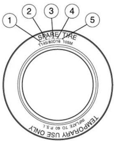
Tires, Wheels and Loading
TIRE PRESSURE MONITORING SYSTEM (TPMS)
Each tire, including the spare (if provided), should be checked monthly when cold and inflated to the inflation pressure recommended by the vehicle manufacturer on the vehicle placard or tire inflation pressure label. (If your vehicle has tires of a different size than the size indicated on the vehicle placard or tire inflation pressure label, you should determine the proper tire inflation pressure for those tires.)
As an added safety feature, your vehicle has been equipped with a tire pressure monitoring system (TPMS) that illuminates a low tire pressure telltale when one or more of your tires is significantly under-inflated. Accordingly, when the low tire pressure telltale illuminates, you should stop and check your tires as soon as possible, and inflate them to the proper pressure. Driving on a significantly under-inflated tire causes the tire to overheat and can lead to tire failure. Under-inflation also reduces fuel efficiency and tire tread life, and may affect the vehicle's handling and stopping ability.
Please note that the TPMS is not a substitute for proper tire maintenance, and it is the driver's responsibility to maintain correct tire pressure, even if under-inflation has not reached the level to trigger illumination of the TPMS low tire pressure telltale.
Your vehicle has also been equipped with a TPMS malfunction indicator to indicate when the system is not operating properly. The TPMS malfunction indicator is combined with the low tire pressure telltale. When the system detects a malfunction, the telltale will flash for approximately one minute and then remain continuously illuminated. This sequence will continue upon subsequent vehicle start-ups as long as the malfunction exists.
When the malfunction indicator is illuminated, the system may not be able to detect or signal low tire pressure as intended. TPMS malfunctions may occur for a variety of reasons, including the installation of replacement or alternate tires or wheels on the vehicle that prevent the TPMS from functioning properly. Always check the TPMS malfunction telltale after replacing one or more tires or wheels on your vehicle to ensure that the replacement or alternate tires and wheels allow the TPMS to continue to function properly.

Tires, Wheels and Loading
The Tire Pressure Monitoring System complies with part 15 of the FCC rules and with RSS-210 of Industry Canada. Operation is subject to the following two conditions: (1) This device may not cause harmful interference, and (2) This device must accept any interference received, including interference that may cause undesired operation.
The Tire Pressure Monitoring System is NOT a substitute for manually checking tire pressure. The tire pressure should be checked periodically (at least monthly) using a tire gauge, see Inflatingyourtires in this chapter. Failure to properly maintain your tire pressure could increase the risk of tire failure, loss of control, vehicle rollover and personal injury.
ChangingtireswithTPMS
Eachroadtireisequipped with atirepressuresensorfastened totheinsiderimofthewheel. Thepressuresensoriscovered bythetireandisnotvisible unlessthetireisremoved.The pressuresensorislocated opposite(180degrees)fromthe valvestem.Caremustbetaken whenchangingthetiretoavoid damagingthesensor.It is
recommended that you always have your tires serviced by an authorized dealer.
The tire pressure should be checked periodically (at least monthly) using an accurate tire gauge, refer to Inflatingyourtiresin this chapter.

Tires, Wheels and Loading
Understanding your Tire Pressure Monitoring System (TPMS)
The Tire Pressure Monitoring System measures pressure in your four road tires and sends the tire pressure readings to your vehicle. The Low Tire Warning Lamp will turn ON if the tire pressure is significantly low. Once the light is illuminated, your tires are under inflated and need to be inflated to the manufacturer's recommended tire pressure. Even if the light turns ON and a short time later turns OFF, your tire pressure still needs to be checked.
Whenyourtemporarysparetireisinstalled
When one of your road tires needs to be replaced with the temporary spare, the TPMS system will continue to identify an issue to remind you that the damaged road wheel/tire needs to be repaired and put back on your vehicle.
To restore the full functionality of the Tire Pressure Monitoring System, have the damaged road wheel/tire repaired and remounted on your vehicle. For additional information, refer to ChangingtireswithTPMS in this section.
When you believe your system is not operating properly
The main function of the Tire Pressure Monitoring System is to warn you when your tires need air. It can also warn you in the event the system is no longer capable of functioning as intended. Please refer to the following chart for information concerning your Tire Pressure Monitoring System:
Tires, Wheels and Loading
| LowTirePressureWarningLight | PossiblecauseC | CustomerActionRequired |
| Solid Warning Light | Tire(s)under-inflated | 1. Check your tire pressure to ensure tires are properly inflated; refer to Inflatingyour tiresin this chapter.2. After inflating your tires to the manufacturer's recommended inflation pressure as shown on the Tire Label (located on the edge of driver's door or the B-Pillar), the vehicle must be driven for at least two minutes over 20 mph (32 km/h) before the light will turn OFF. |
| Spare tire in use | Your temporary spare tire is in use. Repair the damaged road wheel/tire and reinstall it on the vehicle to restore system functionality. For a description on how the system functions, refer to Whenyourtemporary sparetireisinstalledin this section. | |
| TPMSmalfunction | If your tires are properly inflated and your spare tire is not in use and the light remains ON, have the system inspected by your authorized dealer. |
Tires, Wheels and Loading
| LowTirePressureWarningLight | PossiblecauseC | CustomerActionRequired |
| Flashing WarningLight | Spare tire in use | Your temporary spare tire is in use. Repair the damaged road wheel and re-mount it on the vehicle to restore system functionality. For a description of how the system functions under these conditions, refer toWhenyourtemporarysparetireisinstalledin this section. |
| TPMSmalfunction | If your tires are properly inflated and your spare tire is not in use and the TPMS warning light still flashes, have the system inspected by your authorized dealer. |
Wheninflatingyourtires
When putting air into your tires (such as at a gas station or in your garage), the Tire Pressure Monitoring System may not respond immediately to the air added to your tires.
It may take up to two minutes of driving over 20 mph (32 km/h) for the light to turn OFF after you have filled your tires to the recommended inflation pressure.
Howtemperature affects your tire pressure
The Tire Pressure Monitoring System (TPMS) monitors tire pressure in each pneumatic tire. While driving in a normal manner, a typical passenger tire inflation pressure may increase approximately 2 to 4 psi (14 to 28 kPa) from a cold start situation. If the vehicle is stationary over night with the outside temperature significantly lower than the daytime temperature, the tire pressure may decrease approximately 3 psi (20.7 kPa) for a drop of 30° F (16.6°C) in ambient temperature. This lower pressure value may be detected by the TPMS as being significantly lower than the recommended inflation pressure and activate the TPMS warning for low tire pressure. If the low tire pressure warning light is ON, visually check each tire to verify that no tire is flat. (If one or more tires are flat, repair as necessary.) Check air pressure in the road tires. If
Tires, Wheels and Loading
any tire is under-inflated, carefully drive the vehicle to the nearest location where air can be added to the tires. Inflate all the tires to the recommended inflation pressure.
SNOW TIRES AND CHAINS

Snow tires must be the same size and grade as the tires you currently have on your vehicle.
The tires on your vehicle have all weather treads to provide traction in rain and snow. However, in some climates, you may need to use snow tires and cables. If you need to use cables, it is recommended that steel wheels (of the same size and specifications) be used, as cables may chip aluminum wheels.
Follow these guidelines when using snow tires and traction devices:
- SAE class "S" cables should ONLY be used on the front axle for P235/70R16 tires.
- Install cables securely, verifying that the cables or chains do not touch any wiring, brake lines or fuel lines.
- Drive cautiously. If you hear the cables rub or bang against the vehicle, stop and retighten them. If this does not work, remove the cables to prevent vehicle damage.
- Avoid overloading your vehicle.
- Remove the cables when they are no longer needed.
- Do not use cables on dry roads.
- Do not exceed 30 mph (48 km/h) with tire cables on your vehicle.
Consult your authorized dealer for information on other Ford Motor Company approved methods of traction control.
VEHICLE LOADING – WITH AND WITHOUT A TRAILER
This section will guide you in the proper loading of your vehicle and/or trailer, to keep your loaded vehicle weight within its design rating capability, with or without a trailer. Properly loading your vehicle will provide maximum return of vehicle design performance. Before loading your vehicle, familiarize yourself with the following terms for determining your vehicle's weight ratings, with or without a trailer, from the vehicle's Tire Label or Safety Compliance Certification Label:
BaseCurbWeight— is the weight of the vehicle including a full tank of fuel and all standard equipment. It does not include passengers, cargo, or optional equipment.
Tires, Wheels and Loading
VehicleCurbWeight- is the weight of your new vehicle when you picked it up from your authorized dealer plus any aftermarket equipment.

Payload- is the combined weight of cargo and passengers that the vehicle is carrying. The maximum payload for your vehicle can be found on the Tire Label on the B-Pillar or the edge of the driver's door (vehicles exported outside the US and Canada may not have a Tire Label). Look for "THECOMBINEDWEIGHTOFOCCUPANTSAND CARGOSHOULDNEVEREXCEEDXXXkgORXXXlb."for
maximum payload. The payload listed on the Tire Label is the maximum payload for the vehicle as built by the assembly plant. If any aftermarket or authorized-dealer installed equipment has been installed on the vehicle, the weight of the equipment must be subtracted from the payload listed on the Tire Label in order to determine the new payload.
The appropriate loading capacity of your vehicle can be limited either by volume capacity (how much space is available) or by payload capacity (how much weight the vehicle should carry). Once you have reached the maximum payload of your vehicle, do not add more cargo, even if there is space available. Overloading or improperly loading your vehicle can contribute to loss of vehicle control and vehicle rollover.
Tires, Wheels and Loading
Exampleonly:


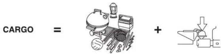
CargoWeight– includes all weight added to the Base Curb Weight, including cargo and optional equipment. When towing, trailer tongue load or king pin weight is also part of cargo weight.
GAW(GrossAxleWeight) – is the total weight placed on each axle (front and rear) – including vehicle curb weight and all payload.
Tires, Wheels and Loading
GAWR(GrossAxleWeightRating)—is the maximum allowable weight that can be carried by a single axle (front or rear). These numbersareshownontheSafetyComplianceCertificationLabel locatedontheB-Pillarortheedgeofthedriver'sdoor. Thetotal loadoneachaxlemustneverexceeditsGAWR.
Note: For trailer towing information refer to Trailer towing found in this chapter or the RVandTrailerTowingGuideprovided by your authorized dealer.

GVW(GrossVehicleWeight)– is the Vehicle Curb Weight + cargo + passengers.
GVWR(GrossVehicleWeight Rating)—is the maximum allowable weight of the fully loaded vehicle (including all options, equipment, passengers and cargo).
TheGVWRisshownonthe SafetyComplianceCertification LabellocatedontheB-Pillaror theedgeofthedriver'sdoor. TheGVWmustneverexceedthe GVWR.
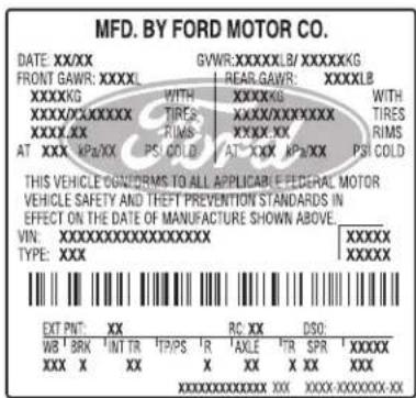
Exceeding the Safety Compliance Certification Label vehicle weight rating limits could result in substandard vehicle handling or performance, engine, transmission and/or structural damage, serious damage to the vehicle, loss of control and personal injury.
Tires, Wheels and Loading

GCW(GrossCombinedWeight)—is the weight of the loaded vehicle (GVW) plus the weight of the fully loaded trailer.
GCWR(GrossCombinedWeightRating)—is the maximum allowable weight of the vehicle and the loaded trailer – including all cargo and passengers – that the vehicle can handle without risking damage. (Important: The towing vehicle's braking system is rated for operation at GVWR, not at GCWR.) Separate functional brakes should be used for safe control of towed vehicles and for trailers where the GCW of the towing vehicle plus the trailer exceed the GVWR of the towing vehicle.
TheGCWmustneverexceedtheGCWR.
MaximumLoadedTrailerWeight- is the highest possible weight of a fully loaded trailer the vehicle can tow. It assumes a vehicle with only mandatory options, no cargo (internal or external), a tongue load of 10–15% (conventional trailer) or king pin weight of 15–25% (fifth wheel trailer), and driver only (150 lb. [68 kg]). Consultyourauthorized dealer(orthervandTrailerTowingGuideprovidedbyyourauthorizeddealer)formoredetailedinformation.
TongueLoaderFifthWheelKingPinWeight refers to the amount of the weight that a trailer pushes down on a trailer hitch.
Examples: For a 5,000 lb. (2,268 kg) conventional trailer, multiply 5,000 by 0.10 and 0.15 to obtain a proper tongue load range of 500 to 750 lb. (227 to 340 kg). For an 11,500 lb. (5,216 kg) fifth wheel trailer, multiply by 0.15 and 0.25 to obtain a proper king pin load range of 1,725 to 2,875 lb. (782 to 1,304 kg)

Do not exceed the GVWR or the GAWR specified on the Safety Compliance Certification Label.

Do not use replacement tires with lower load carrying capacities than the original tires because they may lower the vehicle's R and GAWR limitations. Replacement tires with a higher limit the original tires do not increase the GVWR and GAWR tions.
Tires, Wheels and Loading

Exceeding any vehicle weight rating limitation could result in serious damage to the vehicle and/or personal injury.
Stepsfordeterminingthecorrectloadlimit:
- Locate the statement "The combined weight of occupants and cargo should never exceed XXX kg or XXX lbs." on your vehicle's placard.
- Determine the combined weight of the driver and passengers that will be riding in your vehicle.
- Subtract the combined weight of the driver and passengers from XXX kg or XXX lbs.
- The resulting figure equals the available amount of cargo and luggage load capacity. For example, if the “XXX” amount equals 1,400 lbs. and there will be five 150 lb. passengers in your vehicle, the amount of available cargo and luggage load capacity is 650 lbs. (1400-750 (5 x 150) = 650 lb.). In metric units (635-340 (5 x 68) = 295 kg.)
- Determine the combined weight of luggage and cargo being loaded on the vehicle. That weight may not safely exceed the available cargo and luggage load capacity calculated in Step 4.
-
If your vehicle will be towing a trailer, load from your trailer will be transferred to your vehicle. Consult this manual to determine how this reduces the available cargo and luggage load capacity of your vehicle.
The following gives you a few examples on how to calculate the available amount of cargo and luggage load capacity: -
Another example for your vehicle with 1400 lb. (635 kg) of cargo and luggage capacity. You decide to go golfing. Is there enough load capacity to carry you, 4 of your friends and all the golf bags? You and four friends average 220 lb. (99 kg) each and the golf bags weigh approximately 30 lb. (13.5 kg) each. The calculation would be: 1400 - (5 x 220) - (5 x 30) = 1400 - 1100 - 150 = 150 lb. Yes, you have enough load capacity in your vehicle to transport four friends and your golf bags. In metric units, the calculation would be: 635 kg - (5 x 99 kg) - (5 x 13.5 kg) = 635 - 495 - 67.5 = 72.5 kg.
- A final example for your vehicle with 1400 lb. (635 kg) of cargo and luggage capacity. You and one of your friends decide to pick up cement from the local home improvement store to finish that patio you have been planning for the past 2 years. Measuring the inside of the vehicle with the rear seat folded down, you have room for 12-100 lb. (45 kg) bags of cement. Do you have enough load capacity
Tires, Wheels and Loading
to transport the cement to your home? If you and your friend each weigh 220 lb. (99 kg), the calculation would be: 1400 - (2 x 220) - (12 x 100) = 1400 - 440 - 1200 = -240 lb. No, you do not have enough cargo capacity to carry that much weight. In metric units, the calculation would be: 635 kg - (2 x 99 kg) - (12 x 45 kg) = 635 - 198 - 540 = -103 kg. You will need to reduce the load weight by at least 240 lb. (104 kg). If you remove 3-100 lb. (45 kg) cement bags, then the load calculation would be:
1400 - (2 x 220) - (9 x 100) = 1400 - 440 - 900 = 60 lb. Now you have the load capacity to transport the cement and your friend home. In metric units, the calculation would be: 635 kg - (2 x 99 kg) - (9 x 45 kg) = 635 - 198 - 405 = 32 kg.
The above calculations also assume that the loads are positioned in your vehicle in a manner that does not overload the Front or the Rear Gross Axle Weight Rating specified for your vehicle on the Safety Compliance Certification Label found on the edge of the driver's door.
Special loading instructions for owners of pickup trucks and utility-type vehicles

For important information regarding safe operation of this type of vehicle, see the Preparingtodriveyourvehiclesection in rivingchapter of this Owner'sGuide.

Loaded vehicles may handle differently than unloaded vehicles. Extra precautions, such as slower speeds and increased stopping ice, should be taken when driving a heavily loaded vehicle.
Your vehicle can haul more cargo and people than most passenger cars. Depending upon the type and placement of the load, hauling cargo and people may raise the center of gravity of the vehicle.
TRAILER TOWING
Trailer towing with your vehicle may require the use of a trailer tow option package.
Trailer towing puts additional loads on your vehicle's engine, transaxle, axle, brakes, tires, and suspension. For your safety and to maximize vehicle performance, be sure to use the proper equipment while towing.
Follow these guidelines to ensure safe towing procedure:
- Stay within your vehicle's load limits.
Tires, Wheels and Loading
- Thoroughly prepare your vehicle for towing. Refer to Preparing to tow in this chapter.
- Use extra caution when driving while trailer towing. Refer to Driving whileyoutowin this chapter.
- Service your vehicle more frequently if you tow a trailer. Refer to the severe duty schedule in the scheduled maintenance guide.
- Do not tow a trailer until your vehicle has been driven at least 500 miles (800 km).
- Refer to the instructions included with towing accessories for the proper installation and adjustment specifications.
Do not exceed the maximum loads listed on the Certification label. For load specification terms found on the label, refer to Vehicle loading in this chapter. Remember to figure in the tongue load of your loaded trailer when figuring the total weight.
| FWD | |||
| GCWR(GrossCombinedWeightRating)/TrailerWeights | |||
| EngineMaximum GCWR-lb. (kg) | TrailerWeight Range-lb. (kg) | Maximum frontalareaof trailer-ft 2 (m 2 ) | |
| 2.3L 4820 (2186) 1000 (454) 24 (2.2) | |||
| Notes:For high altitude operation, reduce GCW by 2% per 1000 ft. (300 meters) elevation. For definitions of terms and instructions on calculating your vehicle's load, refer to Vehicle loading in this chapter. Maximum trailer weights shown. The combined weight of the completed towing vehicle and the loaded trailer must not exceed the GCWR. |
| Your Hybrid vehicle is capable of pulling the maximum trailer weight(s) as specified above. Certain states require electric trailer brakes for trailers over a specified weight. Your Hybrid vehicle electrical system is not equipped to accommodate electric trailer brakes. |
Tires, Wheels and Loading
| 4WD | |||
| GCWR(GrossCombinedWeightRating)/TrailerWeights | |||
| EngineMaximumGCWR-lb.(kg) | TrailerWeightRange-lb.(kg) | Maximumfrontalareaoftrailer-ft 2 (m 2 ) | |
| 2.3L 4980 (2259) 1000 (454) 24 (2.2) | |||
| Notes:For high altitude operation, reduce GCW by 2% per 1000 ft.(300 meters) elevation. For definitions of terms and instructions on calculating your vehicle's load, refer to Vehicle loading in this chapter.Maximum trailer weights shown. The combined weight of the completed towing vehicle and the loaded trailer must not exceed the GCWR. | |||
| Your Hybrid vehicle is capable of pulling the maximum trailer weight(s) as specified above. Certain states require electric trailer brakes for trailers over a specified weight. Your Hybrid vehicle electrical system is not equipped to accommodate electric trailer brakes. | |||

Do not exceed the GVWR or the GAWR specified on the certification label.

Towing trailers beyond the maximum recommended gross trailer weight exceeds the limit of the vehicle and could result in the damage, transmission damage, structural damage, loss of vehicle rollo, vehicle rollover and personal injury.
Preparing to tow
Use the proper equipment for towing a trailer and make sure it is properly attached to your vehicle. See your authorized dealer or a reliable trailer dealer if you require assistance.
Hitches
Do not use hitches that clamp onto the vehicle bumper. Use a load carrying hitch. You must distribute the load in your trailer so that 10–15% of the total weight of the trailer is on the tongue.
Tires, Wheels and Loading
Safety chains
Always connect the trailer's safety chains to hook retainers on the vehicle. To connect the trailer's safety chains, cross the chains under the trailer tongue and allow slack for turning corners.
If you use a rental trailer, follow the instructions that the rental agency gives to you.
Donotattachsafetychainstothebumper.
Trailer brakes
Electric, manual, automatic or surge-type brakes, if compatible with the vehicle, are safe if installed properly and adjusted to the manufacturer's specifications. The trailer brakes must meet local and Federal regulations.

Do not connect a trailer's hydraulic brake system directly to your vehicle's brake system. Your vehicle may not have enough up power and your chances of having a collision greatly increase.
The braking system of the tow vehicle is rated for operation at the GVWR not GCWR.
Trailer lamps
Trailer lamps are required on most towed vehicles. Make sure all running lights, brake lights, turn signals and hazard lights are working. Do not connect trailer lamps directly to your vehicle's tail lamps. This can cause damage to your vehicle's electrical system. See your authorized dealer or trailer rental agency for proper instructions and equipment for hooking up trailer lamps.
Driving while you tow
When towing a trailer:
- Keep your speed no faster than 70 mph (112 km/h) during the first 500 miles (800 km) of towing a trailer, and don't make full throttle starts.
- Turn off the speed control. The speed control may shut off automatically when you are towing on long, steep grades.
- Consult your local motor vehicle speed regulations for towing a trailer.
- Anticipate stops and brake gradually.
- Do not exceed the GCWR rating or transmission damage may occur.
Tires, Wheels and Loading
Servicingaftertowing
If you tow a trailer for long distances, your vehicle will require more frequent service intervals. Refer to your scheduled maintenance information for more information.
Trailer towing tips
- Practice turning, stopping and backing up before starting on a trip to get the feel of the vehicle trailer combination. When turning, make wider turns so the trailer wheels will clear curbs and other obstacles.
- Allow more distance for stopping with a trailer attached.
- If you are driving down a long or steep hill, shift to a lower gear. Do not apply the brakes continuously, as they may overheat and become less effective.
- The trailer tongue weight should be 10–15% of the loaded trailer weight.
- If you will be towing a trailer frequently in hot weather, hilly conditions, at GCWR, or any combination of these factors, consider refilling your rear axle with synthetic gear lube if not already so equipped. Refer to the Maintenance and Specifications chapter for the lubricant specification. Remember that regardless of the rear axle lube used, do not tow a trailer for the first 500 miles (800 km) of a new vehicle, and that the first 500 miles (800 km) of towing be done at no faster than 70 mph (112 km/h) with no full throttle starts.
- After you have traveled 50 miles (80 km), thoroughly check your hitch, electrical connections and trailer wheel lug nuts.
- Vehicles with trailers should not be parked on a grade. If you must park on a grade, place wheel chocks under the trailer's wheels.
Launching or retrieving a boat
Disconnectthewiringtothetrailerbeforebackingthetrailer intothewater.Reconnectthewiringtothetrailerafterthe trailerisremovedfromthewater.
When backing down a ramp during boat launching or retrieval:
- do not allow the static water level to rise above the bottom edge of the rear bumper.
- do not allow waves to break higher than 6 inches (15 cm) above the bottom edge of the rear bumper.
Tires, Wheels and Loading
Exceeding these limits may allow water to enter vehicle components:
- causing internal damage to the components.
- affecting driveability, emissions and reliability.
Replace the rear axle lubricant any time the axle has been submerged in water. Rear axle lubricant quantities are not to be checked or changed unless a leak is suspected or repair required.
RECREATIONAL TOWING
An example of “recreational towing” is towing your vehicle behind a motorhome.
Your vehicle may be "flat-towed" (all wheels on the ground) by shifting the transmission into Neutral. This is permitted for Front Wheel Drive (FWD) or Four-Wheel Drive (4WD) vehicles. Your vehicle may be towed up to a speed of 120 km/h (75 mph) but you should always obey local speed limits.
You also have the option of trailering the vehicle with its front wheels on a dolly (FWD only), or trailering with all four wheels off the ground.
For other towing requirements, refer to Wrecker towing in the Roadside Emergencieschapter.
Driving
STARTING
Positions of the ignition
- LOCK, locks the gearshift lever and allows key removal.
- ACCESSORY, allows the electrical accessories such as the radio to operate while the vehicle is not running.
- RUN, all electrical circuits operational and warning lights will illuminate. This is the position the key is in when you're driving.
- START, starts the engine, vehicle and electrical power systems.
![graph TD A["1"] --> B["2"] B --> C["3"] C --> D["4"]](/content/2026/05/1033069/images/d8f295f4e1a4b207aafaa06813ead2f1c1cf62cff2c85c5eafe2d7f1698c7c8d.jpg)
Preparing to start your vehicle
Engine starting is controlled by the electronically-controlled Continuously Variable Transaxle (eCVT). For more information on starting the vehicle, refer to Startingthevehicle in this chapter.
Extended idling at high engine speeds can produce very high temperatures in the engine and exhaust system, creating the risk of fire or other damage.
Do not park, idle, or drive your vehicle in dry grass or other dry ground cover. The emission system heats up the engine compartment and exhaust system, which can start a fire.
Do not start your vehicle in a closed garage or in other enclosed areas. Exhaust fumes can be toxic. Always open the garage door before you start the engine. See Guardingagainstexhaustfumesin this chapter for more instructions.
If you smell exhaust fumes inside your vehicle, have your dealer inspect your vehicle immediately. Do not drive if you smell exhaust fumes.
Driving
Important safety precautions
A computer system controls the engine's idle revolutions per minute (RPM). When the engine starts, the idle RPM runs higher than normal in order to warm the engine. If the engine idle speed does not slow down automatically, have the vehicle checked.
Before starting the vehicle:
- Make sure all vehicle occupants have buckled their safety belts. For more information on safety belts and their proper usage, refer to the SeatingandSafetyRestraintschapter.
- Make sure vehicle accessories are off.
- Make sure the parking brake is set.

- Make sure the gearshift lever is in P (Park).

Driving
- Turn the key to 3 (RUN) without turning the key to 4 (START).
![graph TD A["1"] --> B["2"] B --> C["3"] C --> D["4"]](/content/2026/05/1033069/images/14f83b48144b01335ab19d7232c4888e7cd08f5c8a207e8c6b0cbc41745f6df3.jpg)
Some warning lights will briefly illuminate. See Warninglightsand chimesin the InstrumentClusterchapter for more information regarding the warning lights.
Starting the vehicle
- Turn the key to 3 (RUN) without turning the key to 4 (START). If there is difficulty in turning the key, rotate the steering wheel until the key turns freely. This condition may occur when:
• the front wheels are turned
• a front wheel is against the curb
![graph TD A["1"] --> B["2"] B --> C["3"] C --> D["4"]](/content/2026/05/1033069/images/fc9621f5b6ea25cffc0a04f4638c316700dc9ba250ddc119986b693e8a924dac.jpg)
- Turn the key to 4 (START), then release the key. After the vehicle has been started, a vehicle symbol (called the Ready Indicator Light) will appear in the instrument cluster to indicate the vehicle is on. This

indicator will remain on while the vehicle is on, whether the engine is running or not, to indicate the vehicle is capable of movement (using its electric motor, engine, or both).
Note: After starting the vehicle, the engine may stop running to conserve fuel after it is warmed-up and the high voltage battery is sufficiently charged.
Note: If the vehicle does not start, put the gearshift lever into P (Park), turn the ignition off, then attempt to start the vehicle again. If the vehicle still does not start, it may require refueling, jump starting,
Driving
resetting of the fuel pump/high voltage shut-off switches or service. For information on jump starting the vehicle and resetting the fuel pump/high voltage shut-off switches, refer to the Jumpstartingyour vehicle(lowvoltage[underhood]batteryonly)section, the Jump startingthehighvoltagebatterysection, and the Fuelpump/High voltageshut-offswitchessection found in the RoadsideEmergencies chapter.
Guarding against exhaust fumes
Carbon monoxide is present in exhaust fumes. Take precautions to avoid its dangerous effects.

If you smell exhaust fumes inside your vehicle, have your dealer inspect your vehicle immediately. Do not drive if you smell last fumes.
Important ventilating information
If the engine is idling while the vehicle is stopped for a long period of time, open the windows at least one inch (2.5 cm) or adjust the heating or air conditioning to bring in fresh air.
ENGINE BLOCK/HIGH VOLTAGE BATTERY HEATER (IF EQUIPPED)
An engine block/high voltage battery heater warms the engine coolant and high voltage battery cells which aids in starting, vehicle performance and heater/defroster performance in cold weather. Use of an engine block/high voltage battery heater is strongly recommended if you live in a region where temperatures reach -10°F ( -23°C ) or below. For best results, plug the heater in at least three hours before starting the vehicle. The heater can be plugged in the night before starting the vehicle.

To reduce the risk of electrical shock, do not use your heater with ungrounded electrical systems or two-pronged (cheater) ers.
BRAKES
Occasional brake noise is normal. If a metal-to-metal, continuous grinding or continuous squeal sound is present, the brake linings may be worn-out and should be inspected by an authorized dealer. If the vehicle has continuous vibration or shudder in the steering wheel while braking, the vehicle should be inspected by an authorized dealer.
Refer to Brakesystemwarning light in the InstrumentCluster chapter for information on the brake system warning light.
Under normal operating conditions, brake dust may accumulate on the wheels. Some brake dust is inevitable as brakes wear and does not contribute to brake noise. The use of modern friction materials with emphasis on improved performance and environmental considerations can lead to more dust than in the past. Brake dust can be cleaned by weekly washing with soapy water and a soft sponge. Heavier deposits can be removed with Motorcraft Wheel and Tire Cleaner (ZC-37-A).
Four-wheel anti-lock brake system (ABS)
Your vehicle is equipped with an Anti-lock Braking System (ABS). This system helps you maintain steering control during emergency stops by keeping the brakes from locking. The hydraulic brake system used for regenerative braking is different from other vehicles. The noise from the ABS pump motor and the brake pedal pulsation are much less than on vehicles with conventional ABS. Noise and pedal pulsation during ABS may not be noticed.
The sliding car symbol in the instrument cluster will be illuminated during ABS braking.

The hydraulic brake system used for regenerative braking will charge its hydraulic system at the beginning of a trip and discharge the system at the end of each trip. You may notice a pumping sound when you enter the vehicle or a venting sound a few minutes after parking the vehicle.
UsingABS
When hard braking is required, apply continuous force on the brake pedal; do not pump the brake pedal since this will reduce the effectiveness of the ABS and will increase your vehicle's stopping distance. The ABS will be activated immediately, allowing you to retain steering control during hard braking and on slippery surfaces. However, the ABS does not decrease stopping distance.
Driving
ABSwarninglamp
The ABS lamp in the instrument cluster momentarily illuminates when the ignition is turned on. If the light does not illuminate during start up, remains on or flashes, the ABS may be disabled and may need
Even when the ABS is disabled, normal braking is still effective. (If your BRAKE warning lamp illuminates with the parking brake released, have your brake system serviced immediately by an authori

Regenerative Braking System (RBS)
Your vehicle uses a feature known as regenerative braking. This is used to simulate the engine braking of an internal combustion engine and assist the standard brake system while recovering some of the energy of motion back into the battery to improve fuel economy. The standard brake system is designed to fully stop the car if regenerative braking is not available. During regenerative braking, the motor is spun as a generator to create electrical current. This recharges the high voltage battery and slows the vehicle. In effect, once the accelerator pedal is released, the motor changes from an energy user to an energy producer.
When the accelerator pedal is released or the brake pedal is applied, the brake controller automatically detects the amount of deceleration requested and optimizes how much of the deceleration will be produced by regenerative braking. The remaining portion is generated by standard friction braking. When the battery is almost fully charged, the amount of regenerative braking is limited to avoid overcharging, and the requested deceleration is produced by standard friction braking alone.
Regenerative braking does not take the place of the standard friction brakes; it only assists them. Regenerative braking has also been designed to interact with the anti-lock brake system (ABS). Regenerative braking is disabled when the ABS is activated or the battery is fully charged.
Driving
Parking brake
Apply the parking brake whenever the vehicle is parked. To set the parking brake, press the parking brake pedal down until the pedal stops.

The BRAKE warning lamp in the instrument cluster illuminates and remains illuminated (when the ignition is turned ON) until the parking brake is released.

If the parking brake is fully released, but the brake warning lamp remains illuminated, the brakes may not be working properly.
See your authorized dealer.

Always set the parking brake fully and make sure that the gearshift is securely latched in P (Park).
The parking brake is not recommended to stop a moving vehicle. However, if the normal brakes fail, the parking brake can be used to stop your vehicle in an emergency. Since the parking brake applies only the rear brakes, the vehicle's stopping distance will increase greatly and the handling of your vehicle will be adversely affected.
Driving
Pull the release lever to release the brake. Driving with the parking brake on will cause the brakes to wear out quickly and reduce fuel economy.

STEERING
Your vehicle is equipped with an Electric Power-Assisted Steering (EPAS) system. There is no fluid reservoir to check or fill.
If your vehicle loses electrical power while you are driving (or if the ignition is turned off), you can steer the vehicle manually, but it takes more effort. Under extreme usage conditions, the steering effort may increase. This occurs to prevent overheating and permanent damage to your steering system. If this should occur, you will neither lose the ability to steer the vehicle manually nor will it cause permanent damage. Typical steering and driving maneuvers will allow the system to cool and steering assist will return to normal.
If the steering wanders or pulls, check for:
• an improperly inflated tire
- uneven tire wear
- loose or worn suspension components
- loose or worn steering components
- improper steering alignment
A high crown in the road or high crosswinds may also make the steering seem to wander/pull.
PREPARING TO DRIVE

Utility vehicles have a significantly higher rollover rate than other types of vehicles.

In a rollover crash, an unbelted person is significantly more likely to die than a person wearing a seat belt.
Driving
Utility vehicles and trucks have larger tires and increased ground clearance, giving the vehicle a higher center of gravity than a passenger car.
Vehicles with a higher center of gravity such as utility vehicles and trucks handle differently than vehicles with a lower center of gravity. Utility vehicles and trucks are not designed for cornering at speeds as high as passenger cars any more than low-slung sports cars are designed to perform satisfactorily under off-road conditions. Avoid sharp turns, excessive speed or abrupt maneuvers in these vehicles. Failure to drive cautiously could result in an increased risk of loss of vehicle control, vehicle rollover, personal injury and death.
Loaded vehicles, with a higher center of gravity, may handle differently than unloaded vehicles. Do not overload your vehicle and use extra precautions, such as driving at slower speeds, avoiding abrupt steering changes and allowing for increased stopping distance, when driving a heavily loaded vehicle. Over loading or loading the vehicle improperly can deteriorate handling capability and contribute to loss of vehicle control and vehicle rollover.
This vehicle is equipped with a brake-shift interlock feature that prevents the gearshift lever from being moved from P (Park) when the ignition is in the RUN position unless brake pedal is depressed.
If you cannot move the gearshift lever out of P (Park) with ignition in the RUN position and the brake pedal depressed, it is possible that a fuse has blown or the vehicle's brake lamps are not operating properly. Refer to Fuses and relays in the Roadside Emergencies chapter.
If the fuse is not blown, perform the following procedure:
- Apply the parking brake.
Driving
- Using a screwdriver or similar tool, carefully pry out the small Brake Transmission Shift Interlock (BTSI) cover cap located to the right of the gearshift lever.
- Depress the brake pedal and then start the vehicle.
- Insert a screwdriver or similar tool straight down into the access hole and press downward while pulling the gearshift lever out of the P (Park) position and into the N (Neutral) position.
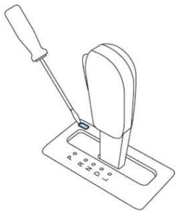
- Remove tool and reinstall BTSI cover cap.
- Release the parking brake and drive normally.

Do not drive your vehicle until you verify that the brakelamps are working.

Always set the parking brake fully and make sure the gearshift is latched in P (Park). Turn the ignition to the LOCK position and we the key whenever you leave your vehicle.

If the parking brake is fully released, but the brake warning lamp remains illuminated, the brakes may not be working properly. Our authorized dealer as soon as possible.
Understanding the gearshift positions of the electronically-controlled Continuously Variable Transaxle (eCVT)

P(Park)
This position locks the transaxle and prevents the front wheels from turning.
To put your vehicle in gear:
- Start the engine
- Release the parking brake
•Depress the brake pedal - Move the gearshift lever into the desired gear
To put your vehicle in P (Park):
- Come to a complete stop
- Move the gearshift lever and securely latch it in P (Park)

Always set the parking brake fully and make sure the gearshift is latched in P (Park). Turn the ignition to the LOCK position and we the key whenever you leave your vehicle.
R(Reverse)
With the gearshift lever in R (Reverse), the vehicle will move backward. Always come to a complete stop before shifting into and out of R (Reverse).
Driving
N(Neutral)
With the gearshift lever in N (Neutral), the vehicle is free to roll; hold the brake pedal down while in this position. Because of the unique nature of the hybrid vehicle, the engine will not start in the N (Neutral) position.
The vehicle does not charge the high voltage battery in the N (Neutral) position. Do not idle the vehicle in N (Neutral) for extended periods as this will discharge your high voltage battery.
D(Drive)
The normal driving position for the best fuel economy.
L(Low)
- Provides maximum engine braking.
- The transmission may be shifted into L (Low) at any vehicle speed.
When parking, do not use the gearshift in place of the parking brake. Always set the parking brake fully and make sure that the gearshift is securely latched in P (Park). Turn off the ignition whenever you leave your vehicle. Never leave your vehicle unattended while it is running. If you do not take these precautions, your vehicle may move unexpectedly and injure someone.
If your vehicle gets stuck in mud or snow
If your vehicle gets stuck in mud or snow, it may be rocked out by shifting between forward and reverse gears, stopping between shifts in a steady pattern. Press lightly on the accelerator in each gear.
Donotrockthevehicleiftheengineisnotatnormaloperating temperatureordamagetothetransmissionmayoccur.
Donotrockthevehicleformorethanaminiteordamagetothe transmissionandtiresmayoccur,ortheenginemayoverheat.
Driving
REVERSE SENSING SYSTEM (IF EQUIPPED)
The Reverse Sensing System (RSS) sounds a tone to warn the driver of obstacles near the rear bumper when R (Reverse) is selected and the vehicle is moving at speeds less than 3 mph (5 km/h). The system is not effective at speeds above 3 mph (5 km/h) and may not detect certain angular or moving objects.
To help avoid personal injury, please read and understand the limitations of the reverse sensing system as contained in this section. Reverse sensing is only an aid for some (generally large and fixed) objects when moving in reverse on a flat surface at "parking speeds". Inclement weather may also affect the function of the RSS; this may include reduced performance or a false activation.
To help avoid personal injury, always use caution when in reverse and when using the RSS.
This system is not designed to prevent contact with small or moving objects. The system is designed to provide a warning to assist the driver in detecting large stationary objects to avoid damaging the vehicle. The system may not detect smaller objects, particularly those close to the ground.
Certain add-on devices such as large trailer hitches, bike or surfboard racks and any device that may block the normal detection zone of the RSS system may create false beeps.
Driving
The RSS detects obstacles up to 6 feet (1.8 meters) from the rear bumper with a decreased coverage area at the outer corners of the bumper, (refer to the figures for approximate zone coverage areas). As you move closer to the obstacle, the rate of the tone increases. When the obstacle is less than 10 inches (25.0 cm) away, the tone will sound continuously. If the RSS detects a stationary or receding object further than 10 inches (25.0 cm) from the side of the vehicle, the tone will sound for only three seconds. Once the system detects an object approaching, the tone will sound again.
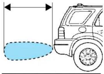

The RSS automatically turns on when the gear selector is placed in R (Reverse) and the ignition is on. An RSS control allows the driver to turn the RSS on and off. To turn the RSS off, the ignition must be on. The system will remain off until either the RSS control is pressed again or the ignition is turned off, then on again. An indicator light on the control will illuminate when the system is turned off. If the indicator light illuminates when the RSS is not turned off, it may indicate a failure in the RSS.

KeeptheRSSsensors(locatedontherearbumper/fascia)free fromsnow,iceandlargeaccumulationsofdirt(donotcleanthe sensorswithsharpobjects).Ifthesensorsarecovered,itwill affecttheaccuracyoftheRSS.
If your vehicles sustains damage to there are bumper/fascia, leaving it misalignedorbent, the sensing zone may be altered causing inaccurate measurement of obstacles or false alarms.
FOUR WHEEL DRIVE (4WD) SYSTEM (IF EQUIPPED)

For important information regarding safe operation of this type of vehicle, see Preparingtodriveyourvehicle in this chapter.
Your vehicle is equipped with an intelligent 4WD System that continuously monitors vehicle conditions and automatically adjusts the power distribution between the front and rear wheels. It combines transparent all-surface operation with highly capable four-wheel drive.
The 4WD system is always active and requires no driver input. It is capable of handling all road conditions, including street and highway driving as well as off-road and winter driving.
Driving off-road with truck and utility vehicles
4WD vehicles are specially equipped for driving on sand, snow, mud and rough terrain and have operating characteristics that are somewhat different from conventional vehicles, both on and off the road.
Howyourvehiclediffersfromothervehicles
Truck and utility vehicles can differ from some other vehicles. Your vehicle may be higher to allow it to travel over rough terrain without getting hung up or damaging underbody components.
The differences that make your vehicle so versatile also make it handle differently than an ordinary passenger car.
Maintain steering wheel control at all times, especially in rough terrain. Since sudden changes in terrain can result in abrupt steering wheel motion, make sure you grip the steering wheel from the outside. Do not grip the spokes.
Drive cautiously to avoid vehicle damage from concealed objects such as rocks and stumps.
You should either know the terrain or examine maps of the area before driving. Map out your route before driving in the area. To maintain steering and braking control of your vehicle, you must have all four wheels on the ground and they must be rolling, not sliding or spinning.
Basicoperatingprinciples
- Drive slower in strong crosswinds which can affect the normal steering characteristics of your vehicle.
- Be extremely careful when driving on pavement made slippery by loose sand, water, gravel, snow or ice.
Driving
If your vehicle goes off the edge of the pavement
- If your vehicle goes off the edge of the pavement, slow down, but avoid severe brake application, and ease the vehicle back onto the pavement only after reducing your speed. Do not turn the steering wheel too sharply while returning to the road surface.
- It may be safer to stay on the apron or shoulder of the road and slow down gradually before returning to the pavement. You may lose control if you do not slow down or if you turn the steering wheel too sharply or abruptly.
- It often may be less risky to strike small objects, such as highway reflectors, with minor damage to your vehicle rather than attempt a sudden return to the pavement which could cause the vehicle to slide sideways out of control or roll over. Remember, your safety and the safety of others should be your primary concern.
Vehicles with a higher center of gravity such as utility and four-wheel drive vehicles handle differently than vehicles with a lower center of gravity. Utility and four-wheel drive vehicles are not designed for cornering at speeds as high as passenger cars any more than low-slung sports cars are designed to perform satisfactorily under off-road conditions. Avoid sharp turns, excessive speed and abrupt maneuvers in these vehicles. Failure to drive cautiously could result in an increased risk of loss of vehicle control, vehicle rollover, personal injury and death.
Ifyourvehiclegetsstuck
If your vehicle gets stuck in mud or snow it may be rocked out by shifting between forward and reverse gears, stopping between shifts, in a steady pattern. Press lightly on the accelerator in each gear.
Donotrockthevehicleiftheengineisnotatnormaloperating temperatureordamagetothetransmissionmayoccur.
Donotrockthevehicleformorethanafewminutesordamage tothetransmissionandtiresmayoccurortheenginemay overheat.
Always set the parking brake fully and make sure the gearshift is latched in P (Park). Turn the ignition to the LOCK position and remove the key whenever you leave your vehicle.
Driving
If the parking brake is fully released, but the brake warning lamp remains illuminated, the brakes may not be working properly. See your authorized dealer.
Do not spin the wheels at over 35 mph (56 km/h). The tires may fail and injure a passenger or bystander.
Emergencymaneuvers
- In an unavoidable emergency situation where a sudden sharp turn must be made, remember to avoid “over-driving” your vehicle, i.e., turn the steering wheel only as rapidly and as far as required to avoid the emergency. Excessive steering will result in less vehicle control, not more. Additionally, smooth variations of the accelerator and/or brake pedal pressure should be utilized if changes in vehicle speed are required. Avoid abrupt steering, acceleration or braking which could result in an increased risk of loss of vehicle control, vehicle rollover and/or personal injury. Use all available road surface to return the vehicle to a safe direction of travel.
- In the event of an emergency stop, avoid skidding the tires and do not attempt any sharp steering wheel movements.
Vehicles with a higher center of gravity such as utility and four-wheel drive vehicles handle differently than vehicles with a lower center of gravity. Utility and four-wheel drive vehicles are not designed for cornering at speeds as high as passenger cars any more than low-slung sports cars are designed to perform satisfactorily under off-road conditions. Avoid sharp turns, excessive speed and abrupt maneuvers in these vehicles. Failure to drive cautiously could result in an increased risk of loss of vehicle control, vehicle rollover, personal injury and death.
- If the vehicle goes from one type of surface to another (i.e., from concrete to gravel) there will be a change in the way the vehicle responds to a maneuver (steering, acceleration or braking). Again, avoid these abrupt inputs.
Sand
When driving over sand, try to keep all four wheels on the most solid area of the trail. Avoid reducing the tire pressures and drive steadily through the terrain. Apply the accelerator slowly and avoid spinning the wheels.
Driving
Avoid excessive speed because vehicle momentum can work against you and cause the vehicle to become stuck to the point that assistance may be required from another vehicle. Remember, you may be able to back out the way you came if you proceed with caution.
Mudandwater
If you must drive through high water, drive slowly. Traction or brake capability may be limited.
When driving through water, determine the depth; avoid water higher than the bottom of the hubs (if possible) and proceed slowly. If the ignition system gets wet, the ve
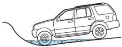
Once through water, always try the brakes. Wet brakes do not stop the vehicle as effectively as dry brakes. Drying can be improved by moving your vehicle slowly while applying light pressure on the brake pedal.
Be cautious of sudden changes in vehicle speed or direction when you are driving in mud. Even 4WD vehicles can lose traction in slick mud. As when you are driving over sand, apply the accelerator slowly and avoid spinning your wheels. If the vehicle does slide, steer in the direction of the slide until you regain control of the vehicle.
If the transmission, transfer case or front axle are submerged in water, their fluids should be checked and changed, if necessary.
Drivingthroughdeepwatermaydamagethetransmission.
If the front or rear axle is submerged in water, the axle lubricant should be replaced.
After driving through mud, clean off residue stuck to rotating driveshafts and tires. Excess mud stuck on tires and rotating driveshafts causes an imbalance that could damage drive components.
"Tread Lightly" is an educational program designed to increase public awareness of land-use regulations and responsibilities in our nation's wilderness areas. Ford Motor

Company joins the U.S. Forest Service and the Bureau of Land Management in encouraging you to help preserve our national forest and other public and private lands by “treading lightly.”
Driving
Drivingonhillyorslopingterrain
Although natural obstacles may make it necessary to travel diagonally up or down a hill or steep incline, you should always try to drive straight up or straight down. Avoiddrivingcrosswiseorturningonsteep
slopesorhills. A danger lies in losing traction, slipping sideways and possibly rolling over. Whenever driving on a hill, determine beforehand the route you will use. Do not drive over the crest of a hill without seeing what conditions are on the other side. Do not drive in reverse over a hill without the aid of an observer.
If you do stall out, do not try to turn around because you might roll over. It is better to back down to a safe location.
Apply just enough power to the wheels to climb the hill. Too much power will cause the tires to slip, spin or lose traction, resulting in loss of vehicle control.
Do not descend a hill in N (Neutral) and avoid sudden hard braking as you could lose control.

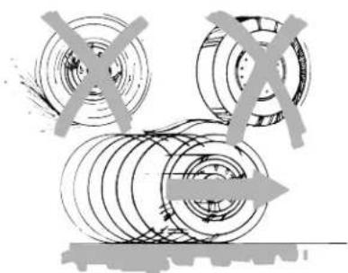
Since your vehicle has anti-lock brakes, apply the brakes steadily. Do not "pump" the brakes.
Driving
Drivingonsnowandice
4WD vehicles have advantages over 2WD vehicles in snow and ice but can skid like any other vehicle.
Should you start to slide while driving on snowy or icy roads, turn the steering wheel in the direction of the slide until you regain control.
Avoid sudden applications of power and quick changes of direction on snow and ice. Apply the accelerator slowly and steadily when starting from a full stop.
Avoid sudden braking as well. Although a 4WD vehicle may accelerate better than a two-wheel drive vehicle in snow and ice, it won't stop any faster, because as in other vehicles, braking occurs at all four wheels. Do not become overconfident as to road conditions.
Make sure you allow sufficient distance between you and other vehicles for stopping; drive slower than usual. Since your vehicle is equipped with a Four Wheel Anti-Lock Brake System (ABS), apply the brake steadily. Do not “pump” the brakes. Refer to the Brakessection of this chapter for additional information on the operation of the anti-lock brake system.
4WD vehicles should be driven with traction devices as referred to in Usingsnowtiresandtractiondevicesin the Tires, Wheelsand Loadingchapter.
MaintenanceandModifications
The suspension and steering systems on your vehicle have been designed and tested to provide durable load carrying capability and predictable performance whether loaded or empty. For this reason, Ford Motor Company strongly recommends that you do not make modifications such as adding or removing parts (such as lift kits or stabilizer bars) or using replacement parts not equivalent to the original factory equipment.
Any modifications to a vehicle that raise the center of gravity can make it more likely the vehicle will roll over as a result of a loss of control. Ford Motor Company recommends that caution be used with any vehicle equipped with a high load or device (such as ladder racks or pickup box cover).
Failure to maintain your vehicle properly may void the warranty, increase your repair cost, reduce vehicle performance and operational capabilities and adversely affect driver and passenger safety. Frequent inspection of vehicle chassis components is recommended if the vehicle is subjected to heavy off-road usage.
Driving
DRIVING THROUGH WATER
If driving through deep or standing water is unavoidable, proceed very slowly especially when the depth is not known. Never drive through water that is higher than the bottom of the wheel rims (for cars) or the bottom of the hubs (for trucks).


When driving through water, traction or brake capability may be limited. Also, water may enter your engine's air intake and severely damage your engine or your vehicle may stall. Drivingthroughdeepwaterwhere thetransmissionventtubeissubmergedmayallowwaterintothe transmissionandcauseinternaltransmissiondamage.
Oncethroughthewater,alwaysdrythebrakesbymovingyour vehicleslowlywhileapplyinglightpressureonthebrakepedal.
Wet brakes do not stop the vehicle as quickly as dry brakes.
Roadside Emergencies
ROADSIDE ASSISTANCE
Getting roadside assistance
To fully assist you should you have a vehicle concern, Ford Motor Company offers a complimentary roadside assistance program. This program is separate from the New Vehicle Limited Warranty. The service is available:
•24-hours, seven days a week
- for the period of five years or 60,000 miles (100,000 km), whichever occurs first on Ford and Mercury vehicles, and six years or 70,000 miles (110,000 km) on Lincoln vehicles.
Roadside assistance will cover:
- a flat tire change with a good spare
- battery jump start
- lock-out assistance (key replacement cost is the customer's responsibility)
- fuel delivery – Independent Service Contractors, if not prohibited by state, local or municipal law shall deliver up to 2.0 gallons (7.5L) of gasoline or 5 gallons (18.9L) of diesel fuel to a disabled vehicle. Fuel delivery service is limited to two no-charge occurrences within a 12-month period.
- winch out – available within 100 feet (30.5 meters) of a paved or county maintained road, no recoveries.
- towing – Ford/Mercury/Lincoln eligible vehicle towed to an authorized dealer within 35 miles (56.3 km) of the disablement location or to the nearest authorized dealer. If a member requests to be towed to an authorized dealer more than 35 miles (56.3 km) from the disablement location, the member shall be responsible for any mileage costs in excess of 35 miles (56.3 km).
Trailers shall be covered up to \$100 if the disabled eligible vehicle requires service at the nearest authorized dealer. If the trailer is disabled, but the towing vehicle is operational, the trailer does not qualify for any roadside services.
If you need towing after the New Vehicle Limited Warranty period has ended, roadside assistance can arrange towing and charge your credit card unless the problem is covered by another Ford warranty. Ford will pay the tow charge under the other warranty.
Roadside Emergencies
CanadiancustomersrefertoyourCustomerInformationGuide forinformationon:
- coverage period
- exact fuel amounts
• towing of your disabled vehicle
• emergency travel expense reimbursement - travel planning benefits
Using roadside assistance
Complete the roadside assistance identification card and place it in your wallet for quick reference. In the United States, this card is found in the Owner Guide portfolio in the glove compartment. In Canada, the card is found in the CustomerInformationGuide in the glove compartment.
U.S. Ford or Mercury vehicle customers who require roadside assistance, call 1-800-241-3673; Lincoln vehicle customers call 1-800-521-4140.
Canadian customers who require roadside assistance, call 1-800-665-2006.
If you need to arrange roadside assistance for yourself, Ford Motor Company will reimburse a reasonable amount. To obtain reimbursement information, U.S. Ford or Mercury vehicles customers call 1-800-241-3673; Lincoln vehicle customers call 1-800-521-4140.
Canadian customers who need to obtain reimbursement information, call 1-800-665-2006.
Roadside coverage beyond basic warranty
In the United States, you may purchase additional roadside assistance coverage beyond this period through the Ford Auto Club by contacting your authorized dealer.
Similarly in Canada, for uninterrupted Roadside Assistance coverage, you may purchase extended coverage prior to your Basic Warranty's Roadside Assistance expiring. For more information and enrollment, contact 1-877-294-2582 or visit our website at www.ford.ca.
Roadside Emergencies
HAZARD FLASHER CONTROL
The hazard flasher is located on the steering column, just behind the steering wheel. The hazard flashers will operate when the ignition is in any position or if the key is not in the ignition.
Push in the flasher control and all front and rear direction signals will flash. Press the flasher control again to turn them off. Use it when your vehicle is disabled and is creating a safety hazard for other motorists.

Note: With extended use, the flasher may run down your low voltage (underhood) battery.
FUEL PUMP/HIGH VOLTAGE SHUT-OFF SWITCHES
The fuel pump shut-off switch stops the electric fuel pump from sending fuel to the engine and the high voltage shut-off switch shuts off power from the high voltage battery when your vehicle receives a substantial physical jolt.
After an accident, if the engine does not start, one or both of the switches may have been activated.
Roadside Emergencies
The fuel pump shut-off switch is located in the front passenger's footwell, behind a flip-up cover.

The high voltage shut-off switch is located in the cargo area on the passenger side of the vehicle in the jack compartment, behind the jack access door. The switch is located behind the jack.

To reset the switch(cs):
- Turn the ignition to LOCK.
- Check the fuel system for leaks.
- If no leaks are apparent, reset the switch by pushing in on the reset button. Both switches should be checked and reset.
- Turn the ignition to RUN.
- Wait a few seconds and return the key to LOCK.
- Make another check for leaks.
Roadside Emergencies
If you see or smell fuel, do not reset the fuel pump shut-off or try to start your vehicle; you could injure yourself or others. Have all the passengers get out of the vehicle and call the local fire department or a towing service.
FUSES AND RELAYS
Fuses
If electrical components in the vehicle are not working, a fuse may have blown. Blown fuses are identified by a broken wire within the fuse. Check the appropriate fuses before replacing any electrical components.

Note: Always replace a fuse with one that has the specified amperage rating. Using a fuse with a higher amperage rating can cause severe wire damage and could start a fire.
Roadside Emergencies
Standardfuseamperageratingandcolor
| COLOR | |||||
| Fuse rating | Mini fuses | Standard fuses | Maxi fuses | Cartridge maxi fuses | Fuselink cartridge |
| 2A Grey — — | — | ||||
| 3A Violet Violet — — | |||||
| 4A Pink Pink — — | — | ||||
| 5A Tan Tan — — | |||||
| 7.5A Brown Brown — — | |||||
| 10A | Red | Red | ——— | ||
| 15A Blue Blue — — | — | ||||
| 20A | Yellow | Yellow | Yellow | Blue | Blue |
| 25A | Natural | Natural | ——— | ||
| 30A | Green | Green | Green Pink Pink | ||
| 40A — | — Orange | Green | Green | ||
| 50A — | — Red | Red | Red | Red | |
| 60A — | — Blue | Yellow | Yellow | ||
| 70A — | — Tan — Brown | ||||
| 80A — | — Natural | Black | Black | ||
Passenger compartment fuse panel
The fuse panel is located on the right-hand side of the center console, by the instrument panel. Remove the panel cover to access the fuse cover. Press the tabs on the top and bottom of the fuse cover to remove.

Roadside Emergencies
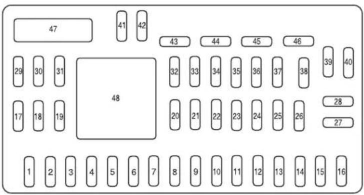
The fuses are coded as follows:
| Fuse/Relay Location | FuseAmp Rating | PassengerCompartmentFuse PanelDescription |
| 1 30A Not used (spare) | ||
| 2 15A Brake On/Off switch | ||
| 3 15A Not used (spare) | ||
| 4 30A 110V inverter | ||
| 5 10A Brake Shift Interlock (BSI), SPDJB | ||
| 6 20A Turn signals, Stop lamps | ||
| 7 10A Low beam headlamps (left) | ||
| 8 10A Low beam headlamps (right) | ||
| 9 15A Interior lights | ||
| 10 15A Backlighting | ||
| 11 10A Four wheel drive | ||
| 12 7.5A Power mirror switch | ||
| 13 7.5A Canister vent | ||
| 14 10A FCIM (radio buttons), Satellite radio, Front display module | ||
| 15 10A Climate control | ||
| 16 15A Not used (spare) |
RoadsideEmergencies
| Fuse/Relay Location | FuseAmp Rating | PassengerCompartmentFuse PanelDescription |
| 1720AAllockmotorfeeds,Liftgate | ||
| 1820AHeatedseat | ||
| 1925ARearwiper | ||
| 2015ADatalink | ||
| 2115AFogamps | ||
| 2215AParklamps | ||
| 2315AHighbeamheadlamps | ||
| 2420AHornrelay | ||
| 2510ADemandlamps | ||
| 2610AINstrumentpanelcluster | ||
| 2720AIgnitionswitch | ||
| 285ARadio | ||
| 295AINstrumentpanelcluster | ||
| 305ANotused(spare) | ||
| 3110ACompassmodule | ||
| 3210ARestraintscontrolmodule | ||
| 3310ASpeedcontrolswitch | ||
| 345ASpeeddcontroldeactivateswitch, ABS | ||
| 3510AFourwheeldrive,EPAS(steering) | ||
| 365APATSTransceiver | ||
| 3710AClimatecontrol | ||
| 3820ASubwoofer/Amp(Audiophileradio) | ||
| 3920ARadio | ||
| 4020AFrontpowerpoint | ||
| 4115ADriver/passengerdoorlockswitches | ||
| 4210ANotused(spare) | ||
| 4310ARearwiperlogic,Heatedseats relay,Autodimmingmirror | ||
| 4410ANotused(spare) | ||
RoadsideEmergencies
| Fuse/Relay Location | FuseAmp Rating | PassengerCompartmentFuse PanelDescription |
| 455AFront | wiperlogic,Blower | motor relay |
| 467.5AOCS(restraints),PADI | (restraints) | |
| 4730ACircuit Breaker | Powerwindows,Moonroof | |
| 48—Delayedaccessoryrelay | ||
Powerdistributionbox
The powerdistributionboxislocated in the engine compartment. The powerdistributionbox contains high-current fuse that protect your vehicle's main electrical systems from overloads.

Always disconnect the low voltage (underhood) battery before servicing high current fuses.

Toreduceriskofelectricalshock,alwaysreplacethecoverto thepowerdistributionboxbeforereconnectingthelowvoltage rhood)batteryorrefillingfluidreservoirs.
Ifthelowvoltage(underhood)batteryhasbeendisconnectedand reconnected,refertotheLowvoltage(underhood)batterysectionof theMaintenanceandSpecificationschapter.

Thefusesarecodedasfollows.
Roadside Emergencies
| Fuse/Relay Location | FuseAmp Rating | PowerDistributionBox Description |
| A80AMidiEPAS | ||
| B125AMidiSPDJB | ||
| 115A*Heatedmirror | ||
| 230A**Reardefroster | ||
| 320A**Rearpowerpoint | ||
| 420A**Fuelinjector | ||
| 510A*PowertrainControlModule | (PCM)KeepAlivepower | |
| 65A*Anti-lockBrakeSystem(ABS) | ||
| 710A*Reverselamps | ||
| 85A*TransaxlcControlModule | (TCM) | |
| 950A**ABS | ||
| 1030A**Frontwipers | ||
| 1130A**PCM/Powersustain | ||
| 1240A**Blowermotor | ||
| 1310A*A/Cclutch | ||
| 1410A*Heater/Coolantpump | ||
| 15 | 50A**TractionBrakeControlModule (TBCM) | |
| 1640A**Coolingfan1 | ||
| 1740A**Coolingfan2 | ||
| 1850A**ABSsolenoid | ||
| 1930A**Powerseats | ||
| 20—A/Cclutchrelay | ||
| 21A—Reardefrosterrelay | ||
| 21B—Notused | ||
| 21C—Blowerrelay | ||
| 21D | —PCMrelay | |
| 22—Notused | ||
| 235A*TBCM | ||
| 2420A*Fuelpump | ||
| 2515A*Ignitioncoils | ||
RoadsideEmergencies
| Fuse/Relay Location | FuseAmp Rating | PowerDistributionBox Description |
| 265A*Interlock | ||
| 2710A*Coolingfan/TCM | ||
| 2815A*HeatedExhaustGasOxygen (HEGO)sensor | ||
| 2915A*PCMpower | ||
| 30A—Coolingfan1relay | ||
| 30B—Powersustainrelay | ||
| 30C—Coolingfanmainrelay | ||
| 30D—Coolingfan2relay | ||
| 31A—Reverselamprelay | ||
| 31B—Injectorrelay | ||
| 31C—Heaterpumprelay | ||
| 31D—Coolantpumprelay | ||
| 31E—Notused | ||
| 31F—Notused | ||
| 32—A/Cclutchdiode | ||
| 33—PCMdiode | ||
| 34—Notused | ||
| 355A*RUN/START | ||
| 36—Notused | ||
| 37—Notused | ||
| *Minifuse**Cartridgefuse | ||
CHANGINGAFLATTIRE
Ifyougetaflattirewhiledriving:
- donotbrakeheavily.
- graduallydecreasethevehicle'sspeed.
• holdthesteeringwheelfirmly. - slowlymovetoasafeplaceonthesideoftheroad.
Yourvehiclemaybeequippedwithaconventionalsparetirethatis differentinoneormoreofthefollowing:type,brand,size,speedrating andtreaddesign.Ifthisisthecase,thisdissimilarsparetireisstillrated foryourvehicleloads(GAWRandGVWR).Thistemporarysparetireis notequippedwithaTirePressureMonitorSystem(TPMS)sensor.
Roadside Emergencies
Note: The tire pressure monitoring system (TPMS) indicator light will illuminate when the spare is in use. To restore the full functionality of the TPMS system, all road wheels equipped with the tire pressure monitoring sensors must be mounted on the vehicle.
Have a flat tire serviced by an authorized dealer in order to prevent damage to the TPMS sensor, refer to TirePressureMonitoringSystem (TPMS) in the Tires, Wheels, and Loading chapter. Replace the spare tire with a road tire as soon as possible. During repairing or replacing of the flat tire, have the authorized dealer inspect the TPMS sensor for damage.

The use of tire sealants may damage your tires. The use of tire sealants may also damage your Tire Pressure Monitoring System should not be used.

Refer to TirePressureMonitoringSystem(TPMS) in the Tire, WheelsandLoadingchapter for important information. If the pressure monitor sensor becomes damaged, it will no longer
Dissimilar spare tire/wheel information

Failure to follow these guidelines could result in an increased risk of loss of vehicle control, injury or death.
If you have a dissimilar spare tire/wheel, then it is intended for temporary use only. This means that if you need to use it, you should replace it as soon as possible with a road tire/wheel that is the same size and type as the road tires and wheels that were originally provided by Ford. If the dissimilar spare tire or wheel is damaged, it should be replaced rather than repaired.
A dissimilar spare tire/wheel is defined as a spare tire and/or wheel that is different in brand, size or appearance from the road tires and wheels and can be one of three types:
- T-type mini-spare: This spare tire begins with the letter "T" for tire size and may have "Temporary Use Only" molded in the sidewall
- Full-sized dissimilarspare with label on wheel: This spare tire has a label on the wheel that states: "THIS TIRE AND WHEEL FOR TEMPORARY USE ONLY"
Roadside Emergencies
When driving with one of the dissimilar spare tires listed above, donot:
• Exceed 50 mph (80 km/h)
- Load the vehicle beyond maximum vehicle load rating listed on the Safety Compliance Label
- Tow a trailer
- Use snow chains on the end of the vehicle with the dissimilar spare tire
- Use more than one dissimilar spare tire at a time
- Use commercial car washing equipment
- Try to repair the dissimilar spare tire
Use of one of the dissimilar spare tires listed above at any one wheel location can lead to impairment of the following:
- Handling, stability and braking performance
- Comfort and noise
• Ground clearance and parking at curbs - Winter weather driving capability
•Wet weather driving capability
For vehicles equipped with 4WD, it is not recommended that the vehicle be operated in 4WD modes with a temporary emergency spare tire. If 4WD operation is necessary, do not operate above speeds of 10 mph (16 km/h) or for distances above 50 miles (80 km).
3. Full-sizedissimilarsparewithoutlabelonwheel
When driving with the full-size dissimilar spare tire/wheel, donot:
• Exceed 70 mph (113 km/h)
- Use more than one dissimilar spare tire/wheel at a time
- Use commercial car washing equipment
- Use snow chains on the end of the vehicle with the dissimilar spare tire/wheel
The usage of a full-size dissimilar spare tire/wheel can lead to impairment of the following:
- Handling, stability and braking performance
- Comfort and noise
• Ground clearance and parking at curbs
Roadside Emergencies
• Winter weather driving capability
• Wet weather driving capability
- All-Wheel driving capability (if applicable)
- Load leveling adjustment (if applicable)
When driving with the full-size dissimilar spare tire/wheel additional caution should be given to:
• Towing a trailer
- Driving vehicles equipped with a camper body
- Driving vehicles with a load on the cargo rack
Drive cautiously when using a full-size dissimilar spare tire/wheel and seek service as soon as possible.
Stoppingandsecuringthevehicle
- Park on a level surface, set the parking brake and activate the hazard flashers.
- Place gearshift lever in P (Park) and turn engine off.
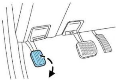
Removingthejackandtools
The jack and tools are located in the right rear of the cargo area behind an access panel.
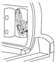
Roadside Emergencies
To remove jack from vehicle:
- Release the thumbscrew on the bracket.
- Release the retention clip on the upper part of the jack bracket.
- Dislodge the jack from the bracket and carefully guide jack down and out through trim opening, upper end out first.

Remove the lug wrench from the jack in order to remove the spare tire from under the vehicle.

Removingthesparetireorsparetireandtether(ifequipped)
- Insert the lug wrench through the access hole in the rear bumper.
- Turn the handle counterclockwise and lower the spare tire until it can be slid rearward and the cable is slack.
- Slide the retainer through the center of the wheel.

2008EscapeHybrid(ehv) OwnersGuide(post-2002-fmt) USA(fus)
Roadside Emergencies
Ifequippedwithatether,performthefollowingadditionalsteps:
- Lift the spare tire on end to access tether attachment (1).

- Use the lug wrench to remove the lug nut from the spare tire tether.
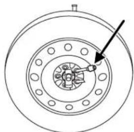
- If not replacing the spare or flat tire to the underbody storage area, raise winch up into the installed position.
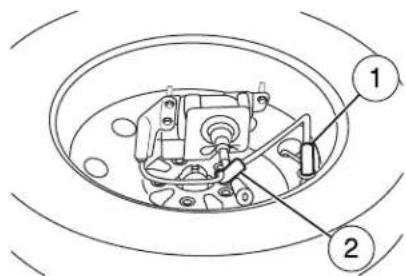
- Use the attached fastener strap (2) to tie the tether end to the winch actuator shaft (if equipped).
Tire change procedure

When one of the front wheels is off the ground, the transmission alone will not prevent the vehicle from moving or slipping off the even if the vehicle is in P (Park).
Roadside Emergencies
To help prevent the vehicle from moving when you change a tire, be sure the parking brake is set, then block (in both directions) the wheel that is diagonally opposite (other side and end of the vehicle) to the tire being changed.
If the vehicle slips off the jack, you or someone else could be seriously injured.
Do not attempt to change a tire on the side of the vehicle close to moving traffic. Pull far enough off the road to avoid the danger of being hit when operating the jack or changing the wheel.
- Block the diagonally opposite wheel.

- Loosen each wheel lug nut one-half turn counterclockwise but do not remove them until the wheel is raised off the ground.

Before placing the jack under the vehicle, NOTE the jack locations:
Roadside Emergencies
- Front
View shown from rear of front tire. Position the jack directly below the protruding bolt.

Roadside Emergencies
•Rear
View shown from forward of rear tire. Position the jack directly below the stud on the rear trailing arm.
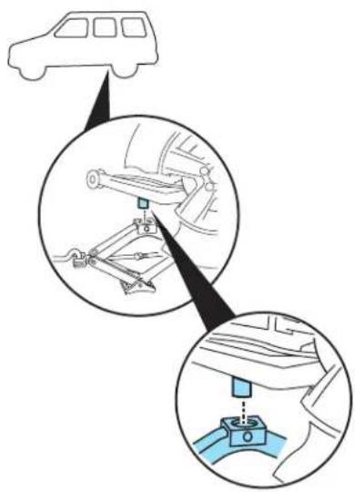
- Position the jack according to the guides and turn the jack handle clockwise until the tire is a maximum of 1 inch (25 mm) off the ground.

Neverusethedifferentialsasa jackingpoint.

To lessen the risk of personal injury, do not put
any part of your body under the vehicle while changing a tire. Do not start the engine when your vehicle is on the jack. The jack is only meant for changing the tire.

Roadside Emergencies
-
Remove the lug nuts with the lug nut wrench.
-
Replace the flat tire with the spare tire, making sure the valve stem is facing outward. Reinstall lug nuts until the wheel is snug against the hub. Do not fully tighten the lug nuts until the wheel has been lowered.
-
Lower the wheel by turning the jack handle counterclockwise.
-
Remove the jack and fully tighten the lug nuts in the order shown. Refer to Wheellugnuttorque specificationslater in this chapter for the proper lug nut torque specification.
![graph TD A["1"] --> B["2"] B --> C["3"] C --> D["4"] D --> E["5"] E --> A style A fill:#f9f,stroke:#333 style B fill:#f9f,stroke:#333 style C fill:#f9f,stroke:#333 style D fill:#f9f,stroke:#333 style E fill:#f9f,stroke:#333](/content/2026/05/1033069/images/68098476cd9cd452e7c6fa58aacf8c03589768c28202c8a28acdc7452d9a6f83.jpg)
Stowingthejackandtools
Make sure the jack is fully lowered and reclip the tools onto the jack.

Reinstall the jack and tools in the cargo area. To replace the jack in the vehicle,
Roadside Emergencies
• guide the jack bottom first in the trim opening and position in the bracket (3),
- secure the retention clip on the upper part of the jack (2), and
- close the thumbscrew (1).
Make sure the jack is fastened so it does not rattle when you drive.

Stowingtheflat/sparetire
Note: Failure to follow spare tire stowage instructions may result in failure of cable or loss of spare tire.
If you are stowing atire that requires reattaching it to the vehicle with a tether, perform these steps first, then proceed with the steps following.
- Place tire on end with valve stem facing rearward, away from vehicle.
- Place tether into bolt holes in wheel and attach lug nut using lug wrench.
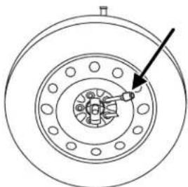
- Lay the tire on the ground with the valve stem facing down. If your vehicle is equipped with aluminum wheels, remove the wheel ornament.
Roadside Emergencies
- Slide the wheel partially under the vehicle and install the retainer through the center of the wheel.
- Turn the jack handle clockwise until the tire is raised to its original position underneath the vehicle. The effort to turn the jack handle increases significantly as the tire contacts the frame. The spare tire carrier will ratchet when the tire is in the fully stowed position. The spare tire carrier has a built-in ratchet feature that will not allow you to overtighten. If the spare tire carrier ratchets with very little effort, take the vehicle to your authorized dealer for assistance at your earliest convenience. If your vehicle is equipped with a trailer hitch, guide the tire with one hand; keep there are of the tire tilted down until the tire clear the bumper.
- Check that the tire lies flat against the frame assembly. Push against the tire to make sure it is tightly seated under the vehicle. Loosen and retighten, if necessary. Failure to properly stow the spare tire may result in failure of the winch cable and loss of the spare tire. (Makesurethat thetiredoesnotcontactthebumper.)
- Repeat this tightness check procedure (every six months, per scheduled maintenance information), when servicing the spare tire pressure or at any time that the spare tire is disturbed through service of other components.
WHEEL LUG NUT TORQUE SPECIFICATIONS
Retighten the lug nuts to the specified torque at 500 miles (800 km) after any wheel disturbance (tire rotation, changing a flat tire, wheel removal, etc.).
| BoltsizeWheellugnuttorque* | ||
| lb.ft.N•m | ||
| M12 x 1.5 100 135 | ||
| * Torque specifications are for nut and bolt threads free of dirt and rust. Use only Ford recommended replacement fasteners. | ||
When a wheel is installed, always remove any corrosion, dirt or foreign materials present on the mounting surfaces of the wheel or the surface of the wheel hub, brake drum or brake disc that contacts the wheel. Ensure that any fasteners that attach the rotor to the hub are secured so they do not interfere with the mounting surfaces of the wheel. Installing wheels without correct metal-to-metal contact at the wheel mounting surfaces can cause the wheel nuts to loosen and the wheel to come off while the vehicle is in motion, resulting in loss of control.
Roadside Emergencies
JUMP STARTING (LOW VOLTAGE [UNDERHOOD] BATTERY ONLY)
Your vehicle has two separate jump starting procedures; the following procedure is for the low voltage (underhood) battery only. Refer to Jumpstartingthehighvoltagebattery in this chapter for information on jump starting the high voltage battery.
![FORD Escape Hybrid (2008) - JUMP STARTING (LOW VOLTAGE [UNDERHOOD] BATTERY ONLY) - 1](/content/2026/05/1033069/images/f05d53d3f590a015dae243de9f847840fe6399f135da7976f01fe8d6d9df889f.jpg)
The gases around the battery can explode if exposed to flames, sparks, or lit cigarettes. An explosion could result in injury or damage.
![FORD Escape Hybrid (2008) - JUMP STARTING (LOW VOLTAGE [UNDERHOOD] BATTERY ONLY) - 2](/content/2026/05/1033069/images/f0cd1222d3a62cb8ba4f7e9be4095fcd68edc9286f4535260c9533b3fedcb203.jpg)
Batteries contain sulfuric acid which can burn skin, eyes and clothing, if contacted.
Donotattempttopush-startyourautomatictransmission vehicle.Automatictransmissionsdonothavepush-start capability.Attemptingtopush-startvehiclewithanautomatic transmissionmaycausetransmissiondamage.
Preparing your vehicle
If your low voltage (underhood) battery becomes disconnected or disabled for any reason, the vehicle controller must relearn the engine's operating characteristics in order to operate it at maximum efficiency. This relearning process occurs the first time the vehicle is driven after reconnecting the low voltage battery. If the learning procedure does not have time to complete during the drive, the engine will continue to operate for 3-5 seconds after you turn the ignition off to complete the relearning process. This is a normal condition and will not re-occur until the low voltage battery is disconnected again. The brake system must also be reset. Refer to Lowvoltage(underhood)batteryin the MaintenanceandSpecificationchapter for more information.
- Useonlya12-voltsupplytostartyourvehicle.
- Do not disconnect the battery of the disabled vehicle as this could damage the vehicle's electrical system.
- Park the booster vehicle close to the hood of the disabled vehicle making sure the two vehicles donottouch. Set the parking brake on both vehicles and stay clear of the engine cooling fan and other moving parts.
- Check all battery terminals and remove any excessive corrosion before you attach the battery cables. Ensure that vent caps are tight and level.
Roadside Emergencies
- Turn the heater fan on in both vehicles to protect from any electrical surges. Turn all other accessories off.
Connecting the jumper cables
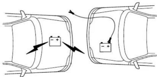
- Connect the positive (+) jumper cable to the positive (+) terminal of the discharged battery.
Note: In the illustrations, lightning bolts are used to designate the assisting (boosting) battery.
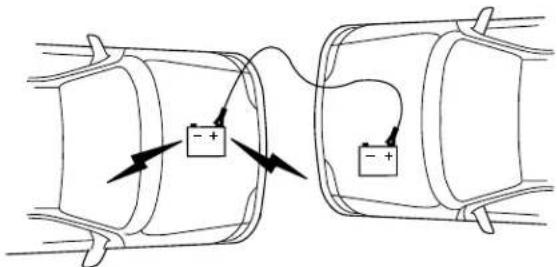
- Connect the other end of the positive (+) cable to the positive (+) terminal of the assisting battery.
Roadside Emergencies

- Connect the negative (-) cable to the negative (-) terminal of the assisting battery.

- Make the final connection of the negative (-) cable to an exposed metal part of the stalled vehicle's engine, away from the battery and the carburetor/fuel injection system. Donotuse fuel lines, engine rocker covers or the intake manifold as groundingpoints.

Do not connect the end of the second cable to the negative (-) terminal of the battery to be jumped. A spark may cause an ion of the gases that surround the battery.
- Ensure that the cables are clear of fan blades, belts, moving parts of both engines, or any fuel delivery system parts.
Roadside Emergencies
Jump starting
- Start the engine of the booster vehicle and run the engine at moderately increased speed.
- Start the engine of the disabled vehicle.
- Once the disabled vehicle has been started, run both engines for an additional three minutes before disconnecting the jumper cables.
Removing the jumper cables
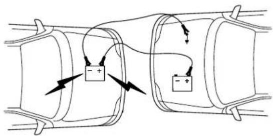
Removethejumpercablesinthereverseorderthattheywere connected.
- Remove the jumper cable from the groundmetal surface.
Note: In the illustrations, lightning bolts are used to designate the assisting (boosting) battery.

- Remove the jumper cable on the negative (-) connection of the booster vehicle's battery.
Roadside Emergencies

- Remove the jumper cable from the positive (+) terminal of the booster vehicle's battery.
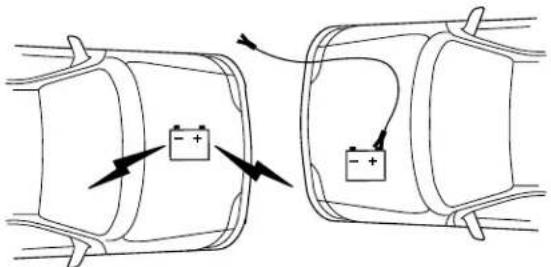
- Remove the jumper cable from the positive (+) terminal of the disabled vehicle's battery.
After the disabled vehicle has been started and the jumper cables removed, allow it to idle for several minutes so the engine computer can relearn its idle conditions.
Your vehicle has two separate jump starting procedures; the following procedure is for the cargo area high voltage battery only. Refer to the Jumpstartingyourvehicle(Lowvoltage[underhood]batteryonly) section in this chapter for information on jump starting the low voltage (underhood) battery.
The gases around the battery can explode if exposed to flames, sparks, or lit cigarettes. An explosion could result in injury or vehicle damage.
Roadside Emergencies

The high voltage battery contains potassium hydroxide (a strong alkaline electrolyte) which can burn skin, eyes and clothing, if cted.
Donotattempttopush-startyourvehicle. This vehicle does not have push-start capability.
If you attempt to start your vehicle and the engine cranks but does not start, the high voltage battery may need to be jump started.
The Service Soon (yellow wrench) light in the instrument cluster may also be illuminated and the message center may display a message.
To jump start the high voltage battery, turn the ignition to OFF, open the access panel on the end of the driver side instrument panel and press the jump start button momentarily. After pressing the button, you should wait eight minutes before attempting to start the engine, otherwise the high voltage battery may not receive sufficient charge to start the engine. The high voltage battery will use voltage from the low voltage (underhood) battery to charge itself.

When the button is pressed, the indicator light on the button will illuminate. After eight minutes has passed, the indicator light will flash rapidly for two minutes. Turn the ignition to RUN. You may now attempt to start the engine. If you attempt to start the engine before the eight minutes passes, the jump starting procedure will stop and will have to be restarted if the engine does not start.
If the engine still does not start after the first complete high voltage jump start, a second jump start procedure can be attempted after a two-minute period (indicated by the button light changing from a rapid flash to no illumination). This jump start procedure can only be done twice before the low voltage (underhood) battery becomes discharged and must also be jump started.
If the jump start button is pressed, but the indicator on the button flashes slowly, the low voltage (underhood) battery may not have enough energy to charge the high voltage battery. If this occurs, refer to the
Roadside Emergencies
Jumpstartingyourvehicle(Lowvoltage[underhood]batteryonly) section in this chapter for information on jump starting the low voltage (underhood) battery. You may perform another high voltage battery jump start by pressing the jump start button after having connected the jumper cables and starting the booster vehicle.
Once the engine is started, the jumper cables should be removed as described in the Jumpstartingyourvehicle(Lowvoltage [underhood]batteryonly)section.
WRECKER TOWING

If you need to have your vehicle towed, contact a professional towing service or, if you are a member of a roadside assistance program, your roadside assistance service provider.
It is recommended that your vehicle be towed with a wheel lift and dollies or flatbed equipment. Do not tow with a slingbelt. Ford Motor Company has not approved a slingbelt towing procedure.
On FWD vehicles, if your vehicle is to be towed from the front, ensure proper wheel lift equipment is used to raise the front wheels off the ground. The rear wheels can be left on the ground when towed in this fashion.
If your vehicle is to be towed from the rear using wheel lift equipment, it is required that the front wheels (drive wheels) be placed on a dolly to prevent damage to the automatic transaxle.
On 4WD vehicles, it is required that your vehicle be towed with a wheel lift and dollies or flatbed equipment with all the wheels off the ground to prevent damage to the automatic transaxle, 4WD system or vehicle.
Roadside Emergencies
If the vehicle is bestowed by other means or incorrectly, vehicle damage may occur.
In case of a roadside emergency with a disabled vehicle (without access to wheel dollies, car hauling trailer, or flatbed transport vehicle) your vehicle (regardless of transmission powertrain configuration) can be flat towed (all wheels on the ground) with the transmission placed in N (Neutral).
Ford Motor Company produces a towing manual for all authorized tow truck operators. Have your tow truck operator refer to this manual for proper hook-up and towing procedures for your vehicle.
Customer Assistance
GETTING THE SERVICES YOU NEED
At home
You must take your Ford vehicle to an authorized dealer for warranty repairs. While any authorized dealer handling your vehicle line will provide warranty service, we recommend you return to your selling authorized dealer who wants to ensure your continued satisfaction. Please note that certain warranty repairs require special training and/or equipment, so not all authorized dealers are authorized to perform all warranty repairs. This means that, depending on the warranty repair needed, you may have to take your vehicle to another authorized dealer. A reasonable time must be allowed to perform a repair after taking your vehicle to the authorized dealer. Repairs will be made using Ford or Motorcraft parts, or remanufactured or other parts that are authorized by Ford.
If you have questions or concerns, or are unsatisfied with the service you are receiving, follow these steps:
- Contact your Sales Representative or Service Advisor at your selling/servicing authorized dealer.
- If your inquiry or concern remains unresolved, contact the Sales Manager, Service Manager or Customer Relations Manager.
- If you require assistance or clarification on Ford Motor Company policies or procedures, please contact the Ford Customer Relationship Center at 1-800-392-3673 (FORD).
Away from home
If you own a Ford or Mercury vehicle and are away from home when your vehicle needs service, or if you need more help than the authorized dealer could provide, after following the steps described above, contact the Ford Customer Relationship Center to find an authorized dealer to help you.
In the United States:
Ford Motor Company
Customer Relationship Center
P.O. Box 6248
Dearborn, MI 48121
1-800-392-3673 (FORD)
(TDD for the hearing impaired: 1-800-232-5952)
www.customersaskford.com
Customer Assistance
In Canada:
Customer Relationship Centre
Ford Motor Company of Canada, Limited
P.O. Box 2000
Oakville, Ontario L6J 5E4
1-800-565-3673 (FORD)
www.ford.ca
If you own a Lincoln vehicle and are away from home when your vehicle needs service, or if you need more help than the authorized dealer could provide, after following the steps described above, contact the Ford Customer Relationship Center to find an authorized dealer to help you.
In the United States:
Ford Motor Company
Customer Relationship Center
P.O. Box 6248
Dearborn, MI 48121
1-800-521-4140
(TDD for the hearing impaired: 1-800-232-5952)
www.customersaskford.com
In Canada:
Lincoln Centre
Ford Motor Company of Canada, Limited
P.O. Box 2000
Oakville, Ontario L6J 5E4
1-800-387-9333
www.lincolncanada.com
In order to help you service your Lincoln vehicle, please have the following information available when contacting the Lincoln Centre:
- Your telephone number (home and business)
- The name of the authorized dealer and the city where the authorized dealer is located
• The year and make of your vehicle
•The date of vehicle purchase
•The current odometer reading
• The vehicle identification number (VIN)
Customer Assistance
Additional Assistance
If you still have a complaint involving a warranty dispute, you may wish to contact the Better Business Bureau (BBB) AUTO LINE program (U.S. only).
In some states (in the U.S.) you must directly notify Ford in writing before pursuing remedies under your state's warranty laws. Ford is also allowed a final repair attempt in some states.
In the United States, a warranty dispute must be submitted to the BBB AUTO LINE before taking action under the Magnuson-Moss Warranty Act, or to the extent allowed by state law, before pursuing replacement or repurchase remedies provided by certain state laws. This dispute handling procedure is not required prior to enforcing state created rights or other rights which are independent of the Magnuson-Moss Warranty Act or state replacement or repurchase laws.
IN CALIFORNIA (U.S. ONLY)
California Civil Code Section 1793.2(d) requires that, if a manufacturer or its representative is unable to repair a motor vehicle to conform to the vehicle's applicable express warranty after a reasonable number of attempts, the manufacturer shall be required to either replace the vehicle with one substantially identical or repurchase the vehicle and reimburse the buyer in an amount equal to the actual price paid or payable by the consumer (less a reasonable allowance for consumer use). The consumer has the right to choose whether to receive a refund or replacement vehicle.
California Civil Code Section 1793.22(b) presumes that the manufacturer has had a reasonable number of attempts to conform the vehicle to its applicable express warranties if, within the first 18 months of ownership of a new vehicle or the first 18,000 miles (29,000 km), whichever occurs first:
- Two or more repair attempts are made on the same non-conformity likely to cause death or serious bodily injury OR
- Four or more repair attempts are made on the same nonconformity (a defect or condition that substantially impairs the use, value or safety of the vehicle) OR
- The vehicle is out of service for repair of nonconformities for a total of more than 30 calendar days (not necessarily all at one time)
Customer Assistance
In the case of 1 or 2 above, the consumer must also notify the manufacturer of the need for the repair of the nonconformity at the following address:
Ford Motor Company
16800 Executive Plaza Drive
Mail Drop 3NE-B
Dearborn, MI 48126
THE BETTER BUSINESS BUREAU (BBB) AUTO LINE PROGRAM (U.S. ONLY)
Your satisfaction is important to Ford Motor Company and to your dealer. Experience has shown that our customers have been very successful in achieving satisfaction by following the three-step procedure outlined on the front page of the Warranty Guide. However, if your warranty concern has not been resolved using the three-step procedure, you may be eligible to participate in the BBB AUTO LINE program.
The BBB AUTO LINE program consists of two parts – mediation and arbitration. Initially, the BBB will try to resolve your question or concern through mediation. Mediation is a process through which a representative of the BBB will contact the parties and explore options for settlement of your claim. If mediation is not successful, customers with eligible claims may participate in the BBB AUTO LINE arbitration process. An arbitration hearing will be scheduled so that you can present your case in an informal setting before an impartial person. The arbitrator will consider the testimony provided and make a decision after the hearing. You are not bound by the decision but may choose to accept it. If you choose to accept the BBB AUTO LINE decision then Ford must abide by the accepted decision as well. If the arbitrator has decided in your favor and you accept the decision, the BBB AUTO LINE program will contact you to ensure that Ford has complied with the decision in a timely manner. Disputes submitted to the BBB AUTO LINE program are usually decided within forty days after you file your claim with the BBB.
To initiate a claim with the BBB AUTO LINE, you will be asked for your name and address, general information about your new vehicle, information about your warranty concerns and any steps you have already taken to try to resolve them. You will then be mailed a Customer Claim Form that you will need to complete, provide proof of vehicle ownership, sign and return the Customer Claim Form to the BBB. Upon receipt, the BBB will review the claim for eligibility under the Program Summary Guidelines.
Customer Assistance
YoucangetmoreinformationbycallingBBBAUTOLINEat 1-800-955-5100,orwritingto:
BBBAUTOLINE 4200WilsonBoulevard,Suite800 Arlington,Virginia22203-1833
Note: Ford Motor Company reserves the right to change eligibility limitations, modify procedures, or to discontinue this process at any time without notice and without obligation.
UTILIZING THE MEDIATION/ARBITRATION PROGRAM (CANADA ONLY)
For vehicles delivered to authorized Canadian dealers. In those cases where you continue to feel that the efforts by Ford of Canada and the authorized dealer to resolve a factory-related vehicle service concern have been unsatisfactory, Ford of Canada participates in an impartial third party mediation/arbitration program administered by the Canadian Motor Vehicle Arbitration Plan (CAMVAP).
The CAMVAP program is a straight-forward and relatively speedy alternative to resolve a disagreement when all other efforts to produce a settlement have failed. This procedure is without cost to you and is designed to eliminate the need for lengthy and expensive legal proceedings.
In the CAMVAP program, impartial third-party arbitrators conduct hearings at mutually convenient times and places in an informal environment. These impartial arbitrators review the positions of the parties, make decisions and, when appropriate, render awards to resolve disputes. CAMVAP decisions are fast, fair, and final as the arbitrator's award is binding both to you and Ford of Canada.
CAMVAP services are available in all territories and provinces. For more information, without charge or obligation, call your CAMVAP Provincial Administrator directly at 1-800-207-0685.
FORD EXTENDED SERVICE PLAN
You can get more protection for your new car or light truck by purchasing Ford Extended Service Plan (Ford ESP) coverage. It provides the following:
- Benefits during the warranty period depending on the plan you purchase (such as: reimbursement for rentals; coverage for certain maintenance and wear items).
- Protection against covered repair costs after your Bumper-to-Bumper Warranty expires.
Customer Assistance
You may purchase Ford ESP from any participating authorized dealer. There are several plans available in various time, distance and deductible combinations which can be tailored to fit your own driving needs. Ford ESP also offers reimbursement benefits for towing and rental coverage.
When you buy Ford ESP, you receive Peace-of-Mind protection throughout the United States and Canada, provided by a network of more than 4,600 participating authorized dealers.
If you did not take advantage of the Ford Extended Service Plan at the time of purchasing your vehicle, you may still be eligible. Since this information is subject to change, please ask your authorized dealer for complete details about Ford Extended Service Plan coverage options, or visit the Ford ESP website at www.ford-esp.com.
GETTING ASSISTANCE OUTSIDE THE U.S. AND CANADA
Before exporting your vehicle to a foreign country, contact the appropriate foreign embassy or consulate. These officials can inform you of local vehicle registration regulations and where to find unleaded fuel.
If you cannot find unleaded fuel or can only get fuel with an anti-knock index lower than is recommended for your vehicle, contact a regional office or owner relations/customer relationship office.
The use of leaded fuel in your vehicle without proper conversion may damage the effectiveness of your emission control system and may cause engine knocking or serious engine damage. Ford Motor Company/Ford of Canada is not responsible for any damage caused by use of improper fuel. Using leaded fuel may also result in difficulty importing your vehicle back into the U.S.
If your vehicle must be serviced while you are traveling or living in Central America, the Caribbean, or the Middle East, contact the nearest authorized dealer. If the authorized dealer cannot help you, write or call:
FORD MOTOR COMPANY FORD EXPORT OPERATIONS
1555 Fairlane Drive
Fairlane Business Park #3
Allen Park, Michigan 48101
U.S.A.
Telephone: (313) 594-4857
FAX: (313) 390-0804
If you are in another foreign country, contact the nearest authorized dealer. If the authorized dealer employees cannot help you, they can direct you to the nearest Ford affiliate office.
238
2008EscapeHybrid(ehv)
OwnersGuide(post-2002-fmt)
USA(fus)
Customer Assistance
If you buy your vehicle in North America and then relocate outside of the U.S. or Canada, register your vehicle identification number (VIN) and new address with Ford Motor Company Export Operations.
CustomersintheU.S.shouldcall1-800-392-3673.
ORDERING ADDITIONAL OWNER'S LITERATURE
To order the publications in this portfolio, contact Helm, Incorporated at:
HELM, INCORPORATED
P.O. Box 07150
Detroit, Michigan 48207
Or call:
Forafreepublicationcatalog,ordertollfree:1-800-782-4356
Monday-Friday 8:00 a.m. - 6:00 p.m. EST
Helm, Incorporated can also be reached by their website: www.helminc.com.
(Itemsinthiscatalogmaybepurchasedbycreditcard, checkor moneyorder.)
Obtaining a French owner's guide
French Owner's Guides can be obtained from your authorized dealer or by writing to:
Ford Motor Company of Canada, Limited
Service Publications CHQ202
The Canadian Road
P.O. Box 2000
Oakville, ON, Canada
L6J 5E4
Customer Assistance
REPORTING SAFETY DEFECTS (U.S. ONLY)
If you believe that your vehicle has a defect which could cause a crash or could cause injury or death, you should immediately inform the
National Highway Traffic Safety
Administration (NHTSA) in addition to notifying Ford Motor Company.
If NHTSA receives similar complaints, it may open an investigation, and if it finds that a safety defect exists in a group of vehicles, it may order a recall and remedy campaign. However, NHTSA cannot become involved in individual problems between you, your dealer, or Ford Motor Company.
To contact NHTSA, you may call the Vehicle Safety Hotline toll-free at 1-888-327-4236 (TTY: 1-800-424-9153); go to http://www.safercar.gov; or write to:
Administrator
NHTSA
400 Seventh Street, SW
Washington, D.C. 20590
You can also obtain other information about motor vehicle safety from http://www.safercar.gov.

REPORTING SAFETY DEFECTS (CANADA ONLY)
If you believe that your vehicle has a defect which could cause a crash or could cause injury or death, you should immediately inform Transport Canada, using their toll-free number: 1-800-333-0510.
Cleaning
WASHING THE EXTERIOR
Wash your vehicle regularly with cool or lukewarm water and a neutral pH shampoo, such as Motorcraft Detail Wash (ZC-3-A), which is available from your authorized dealer.
- Never use strong household detergents or soap, such as dish washing or laundry liquid. These products can discolor and spot painted surfaces.
- Never wash a vehicle that is “hot to the touch” or during exposure to strong, direct sunlight.
- Always use a clean sponge or car wash mitt with plenty of water for best results.
- Dry the vehicle with a chamois or soft terry cloth towel in order to eliminate water spotting.
- It is especially important to wash the vehicle regularly during the winter months, as dirt and road salt are difficult to remove and cause damage to the vehicle.
- Immediately remove items such as gasoline, diesel fuel, bird droppings and insect deposits because they can cause damage to the vehicle's paintwork and trim over time. Use Bug and Tar Remover, ZC-42, which is available from your authorized dealer.
- Remove any exterior accessories, such as antennas, before entering a car wash.
- Suntanlotionsandinsectrepellentscandamageanypainted surface;ifthesesubstancescomeincontactwithyourvehicle, washoffassoonaspossible.
- Use care when washing the vehicle to ensure water and soap arenot directed into the high voltage battery vent, located near the driversiderear window.
Exteriorchrome
- Wash the vehicle first, using cool or lukewarm water and a neutral pH shampoo, such as Motorcraft Detail Wash (ZC-3-A).
- Use Custom Bright Metal Cleaner (ZC-15), available from your authorized dealer. Apply the product as you would a wax to clean bumpers and other chrome parts; allow the cleaner to dry for a few minutes, then wipe off the haze with a clean, dry rag.
- Neveruseabrasivematerialssuchassteelwoolorplasticpads astheycanscratchthechromesurface.
Cleaning
- After polishing chrome bumpers, apply a coating of Motorcraft Premium Liquid Wax (ZC-53-A), available from your authorized dealer, or an equivalent quality product to help protect from environmental effects.
WAXING
Applying Motorcraft Paint Sealant (ZC-45) to your vehicle every six months will assist in reducing minor scratches and paint damage.
- Wash the vehicle first.
- Do not use waxes that contain abrasives; use Motorcraft Premium Liquid Wax (ZC-53-A), which is available from your authorized dealer, or an equivalent quality product.
- Do not allow paint sealant to come in contact with any non-body (low-gloss black) colored trim, such as grained door handles, roof racks, bumpers, side moldings, mirror housings or the windshield cowl area. The paint sealant will "gray" or stain the parts over time.
PAINT CHIPS
Your authorized dealer has touch-up paint to match your vehicle's color. Take your color code (printed on a sticker in the driver's door jamb) to your authorized dealer to ensure you get the correct color.
- Remove particles such as bird droppings, tree sap, insect deposits, tar spots, road salt and industrial fallout before repairing paint chips.
- Always read the instructions before using the products.
ALUMINUM WHEELS AND WHEEL COVERS
Aluminum wheels and wheel covers are coated with a clearcoat paint finish. In order to maintain their shine:
- Clean weekly with Motorcraft Wheel and Tire Cleaner (ZC-37-A), which is available from your authorized dealer. Heavy dirt and brake dust accumulation may require agitation with a sponge. Rinse thoroughly with a strong stream of water.
- Never apply any cleaning chemical to hot or warm wheel rims or covers.
- Some automatic car washes may cause damage to the finish on your wheel rims or covers. Chemical-strength cleaners, or cleaning chemicals, in combination with brush agitation to remove brake dust and dirt, could wear away the clearcoat finish over time.
- Do not use hydrofluoric acid-based or high caustic-based wheel cleaners, steel wool, fuels or strong household detergent.
Cleaning
- To remove tar and grease, use Motorcraft Bug and Tar Remover (ZC-42), available from your authorized dealer.
ENGINE
Engines are more efficient when they are clean because grease and dirt buildup keep the engine warmer than normal. When washing:
- Take care when using a power washer to clean the engine. The high-pressure fluid could penetrate the sealed parts and cause damage.
- Do not spray a hot engine with cold water to avoid cracking the engine block or other engine components.
- Spray Motorcraft Engine Shampoo and Degreaser (ZC-20) on all parts that require cleaning and pressure rinse clean.

- Cover the highlighted areas to prevent water damage when cleaning the engine. Note: As with all transmissions, be especially careful as water entry into the vents can damage internal parts.
- Never wash or rinse the engine while it is running; water in the running engine may cause internal damage.
Cleaning
PLASTIC (NON-PAINTED) EXTERIOR PARTS
Use only approved products to clean plastic parts. These products are available from your authorized dealer.
- For routine cleaning, use Motorcraft Detail Wash (ZC-3-A).
- If tar or grease spots are present, use Motorcraft Bug and Tar Remover (ZC-42).
- For plastic headlamp lenses, use Motorcraft Ultra Clear Spray Glass Cleaner (ZC-23).
WINDOWS AND WIPER BLADES
The windshield, rear and side windows and the wiper blades should be cleaned regularly. If the wipers do not wipe properly, substances on the vehicle's glass or the wiper blades may be the cause. These may include hot wax treatments used by commercial car washes, water repellent coatings, tree sap, or other organic contamination; these contaminants may cause squeaking or chatter noise from the blades, and streaking and smearing of the windshield. To clean these items, follow these tips:
- The windshield, rear windows and side windows may be cleaned with a non-abrasive cleaner such as Motorcraft Ultra-Clear Spray Glass Cleaner (ZC-23), available from your authorized dealer.
- The wiper blades can be cleaned with isopropyl (rubbing) alcohol or Motorcraft Premium Windshield Washer Concentrate (ZC-32-A), available from your authorized dealer. This washer fluid contains special solution in addition to alcohol which helps to remove the hot wax deposited on the wiper blade and windshield from automated car wash facilities. Be sure to replace wiper blades when they appear worn or do not function properly.
- Do not use abrasives, as they may cause scratches.
- Do not use fuel, kerosene, or paint thinner to clean any parts.
If you cannot remove those streaks after cleaning with the glass cleaner or if the wipers chatter and move in a jerky motion, clean the outer surface of the windshield and the wiper blades using a sponge or soft cloth with a neutral detergent or mild-abrasive cleaning solution. After cleaning, rinse the windshield and wiper blades with clean water. The windshield is clean if beads do not form when you rinse the windshield with water.
Donotusesharpobjects,suchasarazorblade,tocleanthe insideoftherearwindowortoremovedecals,asitmaycause damagetotherearwindowdefroster'sheatedgridlines.
Cleaning
INSTRUMENT PANEL/INTERIOR TRIM AND CLUSTER LENS
Clean the instrument panel, interior trim areas and cluster lens with a clean and damp white cotton cloth, then with a clean and dry white cotton cloth; you may also use Motorcraft Dash & Vinyl Cleaner (ZC-38-A) on the instrument panel and interior trim areas.
- Avoid cleaners or polishes that increase the gloss of the upper portion of the instrument panel. The dull finish in this area helps protect the driver from undesirable windshield reflection.
- Be certain to wash or wipe your hands clean if you have been in contact with certain products such as insect repellent and suntan lotion in order to avoid possible damage to the interior painted surfaces.
- Do not use household or glass cleaners as these may damage the finish of the instrument panel, interior trim and cluster lens.

Do not use chemical solvents or strong detergents when cleaning the steering wheel or instrument panel to avoid contamination of rbag system.
If a staining liquid like coffee/juice has been spilled on the instrument panel or on interior trim surfaces, clean as follows:
- Wipe up spilled liquid using a clean white cotton cloth.
- Apply Motorcraft Deluxe Leather and Vinyl Cleaner (ZC-11-A) [In Canada use Motorcraft Multi-Purpose Cleaner (CXC-101)] to the wiped area and spread around evenly.
- Apply more Motorcraft cleaner to a clean white cotton cloth and press the cloth onto the soiled area—allow this to set at room temperature for 30 minutes.
- Remove the soaked cloth, and if it is not soiled badly, use this cloth to clean the area by using a rubbing motion for 60 seconds.
- Following this, wipe area dry with a clean white cotton cloth.
INTERIOR
For fabric, carpets, cloth seats, safety belts and seats equipped with side airbags:
- Remove dust and loose dirt with a vacuum cleaner.
- Remove light stains and soil with Motorcraft Professional Strength Carpet & Upholstery Cleaner (ZC-54).
Cleaning
- If grease or tar is present on the material, spot-clean the area first with Motorcraft Spot and Stain Remover (ZC-14).
- If a ring forms on the fabric after spot cleaning, clean the entire area immediately (but do not oversaturate) or the ring will set.
- Do not use household cleaning products or glass cleaners, which can stain and discolor the fabric and affect the flame retardant abilities of the seat materials.

Do not use cleaning solvents, bleach or dye on the vehicle's safety belts, as these actions may weaken the belt webbing.

Do not use chemical solvents or strong detergents when cleaning the seat-mounted side airbag (if equipped). Such products could dominate the side airbag system and affect performance of the side g in a collision.
LEATHER SEATS (IF EQUIPPED)
Your leather seating surfaces have a clear, protective coating over the leather.
- To clean, use a soft cloth with Motorcraft Deluxe Leather and Vinyl Cleaner (ZC-11-A). Dry the area with a soft cloth.
- To help maintain its resiliency and color, use the Motorcraft Deluxe Leather Care Kit (ZC-11-D), available from your authorized dealer.
- Do not use household cleaning products, alcohol solutions, solvents or cleaners intended for rubber, vinyl and plastics, or oil/petroleum-based leather conditioners. These products may cause premature wearing of the clear, protective coating.
Note: In some instances, color or dye transfer can occur when wet clothing comes in contact with leather upholstery. If this occurs, the leather should be cleaned immediately to avoid permanent staining.
UNDERBODY
Flush the complete underside of your vehicle frequently. Keep body and door drain holes free from packed dirt.
Cleaning
FORD AND LINCOLN MERCURY CAR CARE PRODUCTS
Your Ford or Lincoln Mercury authorized dealer has many quality products available to clean your vehicle and protect its finishes. These quality products have been specifically engineered to fulfill your automotive needs; they are custom designed to complement the style and appearance of your vehicle. Each product is made from high quality materials that meet or exceed rigid specifications. For best results, use the following products or products of equivalent quality:
Motorcraft Bug and Tar Remover (ZC-42)
Motorcraft Car Wash (Canada only) (CXC-21)
Motorcraft Multi-Purpose Cleaner (Canada only) (CXC-101)
Motorcraft Custom Bright Metal Cleaner (ZC-15)
Motorcraft Custom Clear Coat Polish (ZC-8-A)
Motorcraft Custom Vinyl Protectant (U.S. only) (ZC-40-A)
Motorcraft Dash and Vinyl Cleaner (ZC-38-A)
Motorcraft Deluxe Leather and Vinyl Cleaner (U.S. only) (ZC-11-A)
Motorcraft Leather Care Kit (ZC-11-D)
Motorcraft Detail Wash (ZC-3-A)
Motorcraft Dusting Cloth Mitt (ZC-47)
Motorcraft Dusting Cloth (ZC-24)
Motorcraft Engine Shampoo and Degreaser (U.S. only) (ZC-20)
Motorcraft One Step Wash and Wax Concentrate (ZC-6-A)
Motorcraft Paint Sealant (ZC-45)
Motorcraft Premium Glass Cleaner (Canada only) (CXC-100)
Motorcraft Premium Liquid Wax (ZC-53-A)
Motorcraft Premium Windshield Washer Concentrate (ZC-32-A)
Motorcraft Professional Strength Carpet & Upholstery Cleaner (ZC-54)
Motorcraft Spot and Stain Remover (U.S. only) (ZC-14)
Motorcraft Tire Clean and Shine (ZC-28)
Motorcraft Triple Clean (U.S. only) (ZC-13)
Motorcraft Ultra-Clear Spray Glass Cleaner (ZC-23)
Motorcraft Vinyl Cleaner (Canada only) (CXC-93)
Motorcraft Wheel and Tire Cleaner (ZC-37-A)
Maintenance and Specifications
SERVICE RECOMMENDATIONS
To help you service your vehicle, we provide scheduled maintenance information which makes tracking routine service easy.
If your vehicle requires professional service, your authorized dealer can provide the necessary parts and service. Check your Warranty Guideto find out which parts and services are covered.
Use only recommended fuels, lubricants, fluids and service parts conforming to specifications. Motorcraft parts are designed and built to provide the best performance in your vehicle.
PRECAUTIONS WHEN SERVICING YOUR VEHICLE
- Do not work on a hot engine.
- Make sure that nothing gets caught in moving parts.
- Do not work on a vehicle with the engine running in an enclosed space, unless you are sure you have enough ventilation.
- Keep all open flames and other burning (cigarettes) material away from the battery and all fuel related parts.
High Voltage Information

Exposure to high voltage may result in severe personal injury or death. High voltage components must be serviced by a trained technician.
Your vehicle consists of various high voltage components and wiring. All of the high voltage power flows through specific wiring assemblies which are labeled as such and/or are covered with a solid orange convolute or orange stripe tape. Do not come in contact with these components.
The following are specific locations in the rear cargo area that consist of high voltage components and/or wiring.
Maintenance and Specifications

- High voltage connector shield
- Service Disconnect
- High voltage battery case
Working with the engine off
- Set the parking brake and ensure the gearshift is securely latched in P (Park).
- Turn off the engine and remove the key.
- Block the wheels to prevent the vehicle from moving unexpectedly.
Working with the engine on
- Set the parking brake and shift to P (Park).
- Block the wheels.

To reduce the risk of vehicle damage and/or personal burn injuries do not start your engine with the air cleaner removed to not remove it while the engine is running.
Maintenance and Specifications
OPENING THE HOOD
-
Inside the vehicle, pull the hood release handle located under the bottom of the instrument panel.
-
At the front of the vehicle, lift up on the auxiliary latch handle located in the center between the hood and the grille.
-
Lift the hood open and secure it with the prop rod.

Maintenance and Specifications
IDENTIFYING COMPONENTS IN THE ENGINE COMPARTMENT
2.3L I4 engine

- Engine coolant reservoir
- Motor/Electronics (M/E) coolant reservoir
- Engine oil filler cap
- Brake fluid reservoir
- Power distribution box
- Low Voltage (underhood) battery
- Engine air filter assembly
- Engine oil dipstick
- Windshield washer fluid reservoir
Maintenance and Specifications
WINDSHIELD WASHER FLUID

Add fluid to fill the reservoir if the level is low. In very cold weather, do not fill the reservoir completely.

Only use a washer fluid that meets Ford specifications. Do not use any special washer fluid such as windshield water repellent type fluid or bug wash. They may cause squeaking, chatter noise, streaking and smearing. Refer to the Maintenanceproductspecificationsandcapacities section in this chapter.
State or local regulations on volatile organic compounds may restrict the use of methanol, a common windshield washer antifreeze additive. Washer fluids containing non-methanol antifreeze agents should be used only if they provide cold weather protection without damaging the vehicle's paint finish, wiper blades or washer system.
If you operate your vehicle in temperatures below 40° F ( 4.5° C), use washer fluid with antifreeze protection. Failure to use washer fluid with antifreeze protection in cold weather could result in impaired windshield vision and increase the risk of injury or accident.
Note: Do not put washer fluid in the engine coolant reservoir. Washer fluid placed in the cooling system may harm engine and cooling system components.
Checking and adding washer fluid for the liftgate
Washer fluid for the liftgate is supplied by the same reservoir as the windshield.
Maintenance and Specifications
CHANGING THE WIPER BLADES
-
Pull the wiper blade and arm away from the glass. Turn the blade at a right angle to the arm.
-
Squeeze the locking tabs to release the blade from the arm and pull the blade away from the arm to remove it.
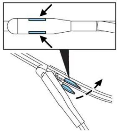
- Attach the new blade to the arm and snap it into place.
Replace wiper blades at least once per year for optimum performance. Poor wiper quality can be improved by cleaning the wiper blades and the windshield, refer to Windows and wiper blades in the Cleaning chapter.
To prolong the life of the wiper blades, it is highly recommended to scrape off the ice on the windshield before turning on the wipers. The layer of ice has many sharp edges and can damage the micro edge of the wiper rubber element.
Maintenance and Specifications
Changing rear window wiper blade
The rear wiper arm is designed without a service position. This reduces the risk of damage to the blade in an automatic car wash.
To replace the wiper blade:
-
Grab the wiper arm just below the blade attachment and pull it as far away from the glass as possible. Do not use excessive force because it can break the wiper arm at the heel. Hold it there until the next step.
-
Grab the wiper blade with your other hand and use your fingers to push the wiper arm tip through the wiper blade center to separate the blade from the arm.
-
Attach the new wiper to the wiper arm and press it into place until a click is heard.
If you find this procedure too difficult, please see your dealer.

ENGINE OIL
Checking the engine oil
Refer to the scheduled maintenance information for the appropriate intervals for checking the engine oil.
- Make sure the vehicle is on level ground.
- Turn the engine off and wait a few minutes for the oil to drain into the oil pan.
- Set the parking brake and ensure the gearshift is securely latched in P (Park).
- Open the hood. Protect yourself from engine heat.
Maintenance and Specifications
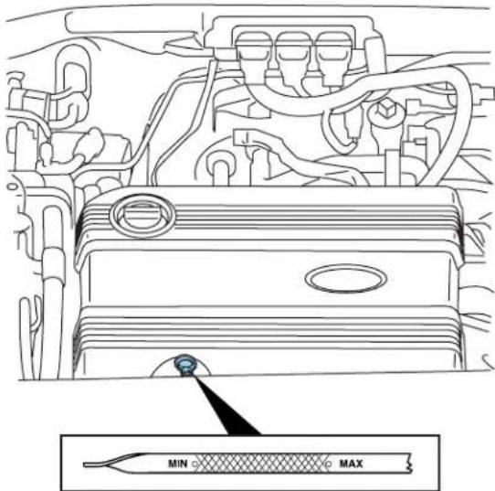
- Locate and carefully remove the engine oil level indicator (dipstick).
-
Wipe the indicator clean. Insert the indicator fully, then remove it again.
-
If the oil level is within the MIN and MAX marks or the lower and upper holes, the oil level is acceptable. DONOTADDOIL.
- If the oil level is below the MIN mark or the lower hole, engine oil mustbeadded to raise the level within the normal operating range.
- If required, add engine oil to the engine. Refer to Adding engine oil in this chapter.
-
Donotoverfilltheenginewithoil.OillevelsabovetheMAX markerupperholemaycauseengine damage. If the engine is overfilled, some oil must be removed from the engine by an authorized dealer.
-
Put the indicator back in and ensure it is fully seated.
Adding engine oil
- Check the engine oil. For instructions, refer to Checkingtheengine oilin this chapter.
Maintenance and Specifications
- If the engine oil level is not within the normal range, add only certified engine oil of the recommended viscosity. Remove the engine oil filler cap and use a funnel to pour the engine oil into the opening.
- Recheck the engine oil level. Make sure the oil level is not above the FULL mark on the engine oil level indicator (dipstick).
- Install the indicator and ensure it is fully seated.
- Fully install the engine oil filler cap by turning the filler cap clockwise 1/4 of a turn until it is seated.
Toavoidpossibleoilloss,DONOToperatethevehiclewiththe engineoillevelindicatorand/ortheengineoilfillercapremoved.
Engine oil and filter recommendations
Look for this certification trademark.

UseSAE5W-20engineoil
Only use oils “Certified For Gasoline Engines” by the American Petroleum Institute (API). An oil with this trademark symbol conforms to the current engine and emission system protection standards and fuel economy requirements of the International Lubricant Standardization and Approval Committee (ILSAC), comprised of U.S. and Japanese automobile manufacturers.
To protect your engine's warranty use Motorcraft SAE 5W-20 or an equivalent SAE 5W-20 oil meeting Ford specification WSS-M2C930-A.
SAE5W-20oilprovidesoptimumfueleconomyanddurability performancemeetingallrequirementsforyourvehicle'sengine.
Do not use supplemental engine oil additives, cleaners or other engine treatments. They are unnecessary and could lead to engine damage that is not covered by Ford warranty.
Change your engine oil and filter according to the appropriate schedule listed in scheduled maintenance information.
Maintenance and Specifications
When changing the oil filter on the 2.3L engine you must also replace the filter cap O-ring. The oil filter drain plug O-ring must also be replaced whenever the oil filter drain plug is removed. Reuse of the O-rings may cause engine oil leakage and may result in severe engine damage. The customer warranty may be void for any damage to the engine if the O-rings are not replaced.
Ford production and aftermarket (Motorcraft) oil filters are designed for added engine protection and long life. If a replacement oil filter is used that does not meet Ford material and design specifications, start-up engine noises or knock may be experienced. It is recommended you use the appropriate Motorcraft oil filter (or another brand meeting Ford specifications) for your engine application.
LOW VOLTAGE (UNDERHOOD) BATTERY

Your vehicle is equipped with a Motorcraft maintenance-free battery which normally does not require additional water during its life of service.

If your battery has a cover/shield, makes sure it is reinstalled after the battery has been cleaned or replaced.
For longer, trouble-free operation, keep the top of the battery clean and dry. Also, make certain the battery cables are always tightly fastened to the battery terminals.
If you see any corrosion on the battery or terminals, remove the cables from the terminals and clean with a wire brush. You can neutralize the acid with a solution of baking soda and water.
Note: Electricalorelectronicaccessoriesorcomponentsaddedto thevehiclebythedealerortheowner(e.g.spotlights,electric winch,etc.)mayadverselyaffectvehicleperformanceand durability.

Batteries normally produce explosive gases which can cause personal injury. Therefore, do not allow flames, sparks or lightedrances to come near the battery. When working near the battery, it's shield your face and protect your eyes. Always provide properation.
Maintenance and Specifications
When lifting a plastic-cased battery, excessive pressure on the end walls could cause acid to flow through the vent caps, resulting in personal injury and/or damage to the vehicle or battery. Lift the battery with a battery carrier or with your hands on opposite corners.
Keep batteries out of reach of children. Batteries contain sulfuric acid. Avoid contact with skin, eyes or clothing. Shield your eyes when working near the battery to protect against possible splashing of acid solution. In case of acid contact with skin or eyes, flush immediately with water for a minimum of 15 minutes and get prompt medical attention. If acid is swallowed, call a physician immediately.
Battery posts, terminals and related accessories contain lead and lead compounds. Washhandsafterhandling.
If the battery is disconnected, the Regenerative Braking System will need to relearn the initial brake pedal position. After reconnecting the battery, slowly depress and release the brake pedal one time. Because your vehicle's engine is electronically controlled by a computer, some control conditions are maintained by power from the battery. When the battery is disconnected or a new battery is installed, the engine must relearn its idle and fuel trim strategy for optimum driveability and performance. To begin this process:
- With the vehicle at a complete stop, set the parking brake.
- Put the gearshift in P (Park), turn off all accessories and start the engine.
- Run the engine until it reaches normal operating temperature.
- Allow the engine to idle for at least one minute.
- Turn the A/C on and allow the engine to idle for at least one minute.
- Drive the vehicle to complete the relearning process.
- The vehicle may need to be driven 10 miles (16 km) or more to relearn the idle and fuel trim strategy.
- If you donot allow the engine to relearn its idle trim, the idle quality of your vehicle may be adversely affected until the idle trim is eventually relearned.
If the battery has been disconnected or a new battery has been installed, the clock and the preset radio stations must be reset once the battery is reconnected.
Maintenance and Specifications
- Always dispose of automotive batteries in a responsible manner. Follow your local authorized standards for disposal. Call your local authorized recycling center to find out more about recycling automotive batteries.
![graph TD A["LEAD"] --> B["RETURN"] B --> C["RECYCLE"] C --> A](/content/2026/05/1033069/images/c53675c3e920470685aa00676f54e9c018d8791ce0d3e61b53846b2154739409.jpg)
Low and high voltage battery – storage
Your vehicle must be started and run for a minimum of 10 minutes once a month in order to maintain the high voltage battery charge. This will maintain the high voltage battery but it is not enough to maintain the low voltage (underhood) battery and additional low voltage (underhood) battery charging may be required after 60 days.
If your vehicle is to be stored for 30 days or longer, the low voltage (underhood) battery negative terminal must be disconnected. Failure to do this could damage your vehicle's batteries.
Maintenance and Specifications
ENGINE COOLANT AND MOTOR/ELECTRONICS COOLANT
Your vehicle is equipped with two separate coolant systems. One is for engine cooling and the other is for various electric motors and other components that are specific to the hybrid operating systems.
Checking engine coolant
The concentration and level of engine coolant should be checked at the intervals listed in scheduled maintenance information. The coolant concentration should be maintained at 50/50 coolant and distilled water, which equates to a freeze point of -34°F (-36°C). Coolant concentration testing is possible with a hydrometer or antifreeze tester (such as the Rotunda Battery and Antifreeze Tester, 014-R1060). The level of coolant should be maintained at the "FULL COLD" level or within the "COLD FILL RANGE" in the coolant reservoir. If the level falls below, add coolant per the instructions in the Addingenginecoolantsection. When the engine is cold, check the level of engine coolant in the reservoir.

Maintenance and Specifications
Checkingmotor/electronics(M/E)coolant
The M/E coolant reservoir is located behind the engine coolant reservoir. Refer to the following engine coolant sections for all information, instructions and warnings related to cooling systems. The two systems use the same coolant and operate similarly, with the Motor and Electronics system generally operating at a lower temperature and pressure. The fluid levels in both reservoirs need to be maintained. When the engine is cold, check the level of M/E coolant in the reservoir.
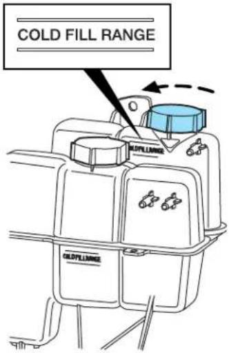
Factoryfillandcoolantspecifications
Your vehicle was factory-filled with a 50/50 engine coolant and water concentration. If the concentration of coolant falls below 40% or above 60%, the engine parts could become damaged or not work properly. A
50-50mixtureofcoolantandwaterprovidesthefollowing:
- Freezeprotectiondownto-34°F(-36°C).
• Boilingprotectionupto265°F(129°C). - Protectionagainstrustandotherformsofcorrosion.
- Enablescalibratedgaugestoworkproperly.
Commoninstructionsforcoolingsystems
- The engine coolant should be at the "FULL COLD" level or within the "COLD FILL RANGE" as listed on the engine coolant reservoir (depending upon application).
- Refer to the scheduled maintenance information for service interval schedules.
- Be sure to read and understand Precautionswhenservicingyour vehicle in this chapter.
Maintenance and Specifications
If the engine coolant has not been checked at the recommended interval, the engine coolant reservoir may become low or empty. If the reservoir is low or empty, add engine coolant to the reservoir. Refer to Adding enginecoolant in this chapter.
Note: Automotive fluids are not interchangeable; do not use engine coolant, antifreeze or windshield washer fluid outside of its specified function and vehicle location.
Adding engine coolant
When adding coolant, make sure it is a 50/50 mixture of engine coolant and distilled water. Add the mixture to the coolant reservoir, whenthe engineiscool, until the appropriate fill level is obtained.

Do not add engine coolant when the engine is hot. Steam and scalding liquids released from a hot cooling system can burn you. Also, you can be burned if you spill coolant on hot engine parts.

Do not put engine coolant in the windshield washer fluid container. If sprayed on the windshield, engine coolant could it difficult to see through the windshield.
- AddMotorcraftPremiumGoldEngineCoolantorequivalent meetingFordspecificationWSS-M97B51-A1.Refer to
Maintenanceproductspecificationsandcapacitiesin this chapter.
Note: Use of Motorcraft Cooling System Stop Leak Pellets or an equivalent product meeting Ford specification WSS-M99B37-B6, may darken the color of Motorcraft Premium Gold Engine Coolant from yellow to golden tan.
- Donotadd/mixanorange-colored,extendedlifecoolantsuch asMotorcraftSpecialtyOrangeEngineCoolant,meetingFord specificationWSS-M97B44-D,orDEX-COOL®brandwiththe factory-filledcoolant.Mixing Motorcraft Specialty Orange Engine Coolant or any orange-colored extended life product such as DEX-COOL®brand with your factory filled coolant can result in degraded corrosion protection.
- A large amount of water without engine coolant may be added, in case of emergency, to reach a vehicle service location. In this instance, the cooling system must be drained and refilled with a 50/50 mixture of engine coolant and distilled water as soon as possible. Water alone (without engine coolant) can cause engine damage from corrosion, overheating or freezing.
Maintenance and Specifications
- Donotusealcohol, methanol, brineoranyenginecoolants mixed with alcoholormethanolantifreeze(coolant). Alcohol and other liquids can cause engine damage from overheating or freezing.
- Donotaddextrainhibitorsoradditivestothecoolant. These can be harmful and compromise the corrosion protection of the engine coolant.
For vehicles with overflow coolant systems with a non-pressurized cap on the coolant recovery system, add coolant to the coolant recovery reservoir when the engine is cool. Add the proper mixture of coolant and water to the “FULL COLD” level. For all other vehicles which have a coolant degas system with a pressurized cap, or if it is necessary to remove the coolant pressure relief cap on the radiator of a vehicle with an overflow system, follow these steps to add engine coolant.
To reduce the risk of personal injury, make sure the engine is cool before unscrewing the coolant pressure relief cap. The cooling system is under pressure; steam and hot liquid can come out forcefully when the cap is loosened slightly.
- Before you begin, turn the engine off and let it cool.
- When the engine is cool, wrap a thick cloth around the coolant pressure relief cap on the coolant reservoir (a translucent plastic bottle). Slowly turn cap counterclockwise (left) until pressure begins to release.
- Step back while the pressure releases.
- When you are sure that all the pressure has been released, use the cloth to turn it counterclockwise and remove the cap.
- Fill the coolant reservoir slowly with the proper coolant mixture (see above), to within the "COLD FILL RANGE" or the "FULL COLD" level on the reservoir. If you removed the radiator cap in an overflow system, fill the radiator until the coolant is visible and radiator is almost full.
- Replace the cap. Turn until tightly installed. (Cap must be tightly installed to prevent coolant loss.)
After any coolant has been added, check the coolant concentration (refer to Checkingenginecoolant). If the concentration is not 50/50 (protection to -34°F/-36°C ), drain some coolant and adjust the concentration. It may take several drains and additions to obtain a 50/50 coolant concentration.
Whenever coolant has been added, the coolant level in the coolant reservoir should be checked the next few times you drive the vehicle. If
Maintenance and Specifications
necessary, add enough 50/50 concentration of engine coolant and distilled water to bring the liquid level to the proper level.
If you have to add more than 1.0 quart (1.0 liter) of engine coolant per month, have your authorized dealer check the engine cooling system. Your cooling system may have a leak. Operating an engine with a low level of coolant can result in engine overheating and possible engine damage.
Recycled engine coolant
Ford Motor Company does NOT recommend the use of recycled engine coolant in vehicles originally equipped with Motorcraft Premium Gold Engine Coolant since a Ford-approved recycling process is not yet available.

Used engine coolant should be disposed of in an appropriate
manner. Follow your community's regulations and standards for recycling and disposing of automotive fluids.
Coolant refill capacity
To find out how much fluid your vehicle's cooling system can hold, refer to Maintenance product specifications and capacities in this chapter.
Fill your engine coolant reservoir as outlined in Addingenginecoolant in this section.
Severe climates
If you drive in extremely cold climates (less than -34°F[-36°C] ):
- Itmaybenecessarytoincreasethecoolantconcentration above50%.
- NEVERincreasethecoolantconcentrationabove60%.
- Increased engine coolant concentrations above 60% will decrease the overheat protection characteristics of the engine coolant and may cause engineered damage.
- Refertothechartonthecoolantcontainertoensurethe coolantconcentrationinyourvehiclewillprovideadequate freezeprotectionatthetemperaturesinwhichyoudriveinthe wintermonths.
If you drive in extremely hot climates:
- Itisstillnecessarytomaintainthecoolantconcentration above40%.
Maintenance and Specifications
- NEVERdecreasethecoolantconcentrationbelow40%.
- Decreasedenginecoolantconcentrationsbelow 40% will decreasethecorrosionprotectioncharacteristicsoftheengine coolantandmaycauseenginedamage.
- Decreasedenginecoolantconcentrationsbelow 40% will decreasethefreezeprotectioncharacteristicsoftheengine coolantandmaycauseenginedamage.
- Refertothechartonthecoolantcontainertoensurethe coolantconcentrationinyourvehiclewillprovideadequate protectionatthetemperaturesinwhichyoudrive.
Vehicles driven year-round in non-extreme climates should use a 50/50 mixture of engine coolant and distilled water for optimum cooling system and engine protection.
FUEL FILTER
For fuel filter replacement, see your authorized dealer. Refer to scheduled maintenance information for the appropriate intervals for changing the fuel filter.
ReplacethefuelfilterwithanaauthorizedMotorcraftpart.The customerwarrantymaybevoidforanydamagetothefuelsystem ifanaauthorizedMotorcraftfuelfilterisnotused.
WHAT YOU SHOULD KNOW ABOUT AUTOMOTIVE FUELS

Important safety precautions

Do not overfill the fuel tank. The pressure in an overfilled tank may cause leakage and lead to fuel spray and fire.

The fuel system may be under pressure. If the fuel filler cap is venting vapor or if you hear a hissing sound, wait until it stops completely removing the fuel filler cap. Otherwise, fuel may out and injure you or others.

If you do not use the proper fuel filler cap, excessive vacuum in the fuel tank may damage the fuel system or cause the fuel cap engage in a collision, which may result in possible personal injury.
Maintenance and Specifications

Automotive fuels can cause serious injury or death if misused or mishandled.

Gasoline may contain benzene, which is a cancer-causing agent.
Observe the following guidelines when handling automotive fuel:
- Extinguish all smoking materials and any open flames before refueling your vehicle.
• Always turn off the vehicle before refueling. - Automotive fuels can be harmful or fatal if swallowed. Fuel such as gasoline is highly toxic and if swallowed can cause death or permanent injury. If fuel is swallowed, call a physician immediately, even if no symptoms are immediately apparent. The toxic effects of fuel may not be visible for hours.
- Avoid inhaling fuel vapors. Inhaling too much fuel vapor of any kind can lead to eye and respiratory tract irritation. In severe cases, excessive or prolonged breathing of fuel vapor can cause serious illness and permanent injury.
- Avoid getting fuel liquid in your eyes. If fuel is splashed in the eyes, remove contact lenses (if worn), flush with water for 15 minutes and seek medical attention. Failure to seek proper medical attention could lead to permanent injury.
- Fuels can also be harmful if absorbed through the skin. If fuel is splashed on the skin and/or clothing, promptly remove contaminated clothing and wash skin thoroughly with soap and water. Repeated or prolonged skin contact with fuel liquid or vapor causes skin irritation.
- Be particularly careful if you are taking “Antabuse” or other forms of disulfiram for the treatment of alcoholism. Breathing gasoline vapors, or skin contact could cause an adverse reaction. In sensitive individuals, serious personal injury or sickness may result. If fuel is splashed on the skin, promptly wash skin thoroughly with soap and water. Consult a physician immediately if you experience an adverse reaction.
Maintenance and Specifications

When refueling always shut the engine off and never allow sparks or open flames near the filler neck. Never smoke while ing. Fuel vapor is extremely hazardous under certain conditions. should be taken to avoid inhaling excess fumes.

The flow of fuel through a fuel pump nozzle can produce static electricity, which can cause a fire if fuel is pumped into an unded fuel container.
Refueling

Fuel vapor burns violently and a fuel fire can cause severe injuries. To help avoid injuries to you and others:
- Read and follow all the instructions on the pump island;
- Turn off your engine when you are refueling;
- Do not smoke if you are near fuel or refueling your vehicle;
- Keep sparks, flames and smoking materials away from fuel;
- Stay outside your vehicle and do not leave the fuel pump unattended when refueling your vehicle — this is against the law in some places;
- Keep children away from the fuel pump; never let children pump fuel.
Use the following guidelines to avoid electrostatic charge build-up when filling an ungrounded fuel container:
- Place approved fuel container on the ground.
- DO NOT fill a fuel container while it is in the vehicle (including the cargo area).
- Keep the fuel pump nozzle in contact with the fuel container while filling.
- DO NOT use a device that would hold the fuel pump handle in the fill position.
Fuel Filler Cap
Your fuel tank filler cap has an indexed design with a 1/4 turn on/off feature.
When fueling your vehicle:
- Turn the engine/ignition switch to the off position.
Maintenance and Specifications
- Carefully turn the filler cap counterclockwise until it spins off.
- To install the cap, align the lugs on the cap with the threads on the filler pipe.
- Turn the filler cap clockwise until it clicks at least once.
After refueling, if the “CHECK FUEL CAP” indicator comes on and stays on when you start the engine, the fuel filler cap may not be properly installed. Turn off the engine, remove the fuel filler cap, align the cap properly and reinstall it securely. The “CHECK FUEL CAP” indicator should turn off after three driving cycles with the fuel filler cap properly installed. A driving cycle consists of a cold engine start-up followed by mixed city/highway driving.
Ifyoumustreplacethefuelfillercap,replaceitwithafuelfiller capthatisdesignedforyourvehicle.Thecustomerwarrantymay bevoidforanydamagetothefueltankorfuelsystemifthe correctgenuineFordorMotorcraftfuelfillercapisnotused.

The fuel system may be under pressure. Remove fuel filler cap slowly. Otherwise, fuel may spray out and injure you or others.

If you do not use the proper fuel filler cap, excessive vacuum in the fuel tank may damage the fuel system or cause the fuel cap engage in a collision, which may result in possible personal injury.
FORD RECOMMENDS BP

Choosing the right fuel
Use only UNLEADED fuel or UNLEADED fuel blended with a maximum of 10% ethanol. Your vehicle was not designed to run on E85 fuels that are blended with a maximum of 85% ethanol. The use of leaded fuel is prohibited by law and could damage your vehicle. Do not use fuel containing methanol. It can damage critical fuel system components.
Maintenance and Specifications
Your vehicle was not designed to use fuel or fuel additives with metallic compounds, including manganese-based additives. Studies indicate that these additives can cause your vehicle's emission control system to deteriorate more rapidly.
Repairs to correct the effects of using a fuel for which your vehicle was not designed may not be covered by your warranty.
Octane recommendations
Your vehicle is designed to use “Regular” unleaded gasoline with pump (R+M)/2 octane rating of 87. We do not recommend the use of gasolines labeled as “Regular” that are sold with octane ratings of 86 or lower in high altitude areas.
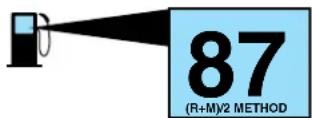
Do not be concerned if your engine sometimes knocks lightly. However, if it knocks heavily under most driving conditions while you are using fuel with the recommended octane rating, see your authorized dealer to prevent any engine damage.
Fuel quality
If you are experiencing starting, rough idle or hesitation driveability problems, try a different brand of unleaded gasoline. "Premium" unleaded gasoline is not recommended for vehicles designed to use "Regular" unleaded gasoline because it may cause these problems to become more pronounced. If the problems persist, see your authorized dealer.
Do not add aftermarket fuel additive products to your fuel tank. It should not be necessary to add any aftermarket products to your fuel tank if you continue to use high quality fuel of the recommended octane rating. These products have not been approved for your engine and could cause damage to the fuel system. Repairs to correct the effects of using an aftermarket product in your fuel may not be covered by your warranty.
Many of the world's automakers approved the World-Wide Fuel Charter that recommends gasoline specifications to provide improved performance and emission control system protection for your vehicle. Gasolines that meet the World-Wide Fuel Charter should be used when available. Ask your fuel supplier about gasolines that meet the World-Wide Fuel Charter.
Maintenance and Specifications
Cleaner air
Ford endorses the use of reformulated “cleaner-burning” gasolines to improve air quality, per the recommendations in the ChoosingtheRight Fuelsection.
Running out of fuel
Avoid running out of fuel because this situation may have an adverse effect on powertrain components.
If you have run out of fuel:
- You may need to cycle the ignition from OFF to ON several times after refueling to allow the fuel system to pump the fuel from the tank to the engine. On restarting, cranking time will take a few seconds longer than normal.
- Normally, adding 1 gallon (3.8L) of fuel is enough to restart the engine. If the vehicle is out of fuel and on a steep grade, more than 1 gallon (3.8L) may be required.
- The 📄 indicator may come on. For more information on the “check engine” or the “service engine soon” indicator, refer to Warninglights andchimes in the InstrumentClusterchapter.
ESSENTIALS OF GOOD FUEL ECONOMY
Measuring techniques
Your best source of information about actual fuel economy is you, the driver. You must gather information as accurately and consistently as possible. Fuel expense, frequency of fill-ups or fuel gauge readings are NOT accurate as a measure of fuel economy. We do not recommend taking fuel economy measurements during the first 1,000 miles (1,600 km) of driving (engine break-in period). You will get a more accurate measurement after 2,000 miles–3,000 miles (3,000 km–5,000 km).
Filling the tank
When the fuel gauge indicates empty, there is still a small reserve of fuel in the fuel system. When refueling your vehicle after the fuel gauge indicates empty, you might not be able to refuel the full amount of the advertised capacity of the fuel tank due to the empty reserve still present in the tank. The amount of usable fuel in the empty reserve varies and should not be relied upon to increase driving range.
Maintenance and Specifications
For consistent results when filling the fuel tank:
- Turn the engine/ignition switch to the off position prior to refueling; an error in the reading will result if the engine is left running.
- Allow no more than two automatic click-offs when filling.
- Always use fuel with the recommended octane rating.
- Use a known quality gasoline, preferably a national brand.
Your results will be most accurate if your filling method is consistent.
Calculating fuel economy
- Fill the fuel tank completely and record the initial odometer reading (in miles or kilometers).
- Each time you fill the tank, record the amount of fuel added (in gallons or liters).
- After at least three to five tank fill-ups, fill the fuel tank and record the current odometer reading.
- Subtract your initial odometer reading from the current odometer reading.
- Follow one of the simple calculations in order to determine fuel economy:
Calculation 1: Dividetotalmilestraveledbytotalgallonsused.
Calculation 2: Multiplylitersusedby100,thendividebytotal kilometerstraveled.
Keep a record for at least one month and record the type of driving (city or highway). This will provide an accurate estimate of the vehicle's fuel economy under current driving conditions. Additionally, keeping records during summer and winter will show how temperature impacts fuel economy. In general, lower temperatures give lower fuel economy.
Driving style — good driving and fuel economy habits
Since it is able to operate in electric mode and to collect braking energy, your hybrid vehicle will get better fuel economy in city driving than on the highway. This is contrary to conventional vehicles. However, many of the same actions that improve fuel economy in a conventional vehicle will also improve fuel economy in this vehicle.
Give consideration to the lists that follow and you may be able to improve your fuel economy.
Habits
- Avoid aggressive driving. Quick acceleration and deceleration decrease fuel economy.
Maintenance and Specifications
- Drive at a smooth, constant speed. Excessive variation in pedal input causes more operating mode changes and reduces efficiency.
- Drive at reasonable speeds. Traveling at 60 mph [96 km/h] uses approximately 20% less fuel than traveling at 70 mph [112 km/h]).
- Minimize A/C and defroster usage. Selecting defrost, or defrost/floor mode on the climate control system will force the engine to run continuously, which reduces fuel economy. Selecting AUTO will typically force the engine to run continuously, unless ECON is selected.
- Minimize temperature extremes when the vehicle is parked, for example by storing in a garage to avoid extreme cold in winter and extreme sun loads in summer. The high voltage battery operates more efficiently in moderate temperatures.
- Combine errands. Your vehicle is more fuel efficient when the engine is warm. Driving to your farthest destination first will warm the engine more quickly and may improve fuel economy for the rest of the trip.
Maintenance
- Keep tires properly inflated and use only recommended size.
- Keep wheels properly aligned.
- Use recommended engine oil. Refer to Lubricantspecifications in this chapter.
- Perform all regularly scheduled maintenance items. Follow the recommended maintenance schedule and owner maintenance checks found in scheduledmaintenanceinformation.
Conditions
- Heavily loading a vehicle or towing a trailer may reduce fuel economy at any speed.
- Carrying unnecessary weight may reduce fuel economy (approximately 1 mpg [0.4 km/L] is lost for every 300 lb [136 kg] of weight carried).
- Adding certain accessories to your vehicle (for example bug deflectors, rollbars/light bars, running boards, ski/luggage racks, flags) may reduce fuel economy.
- Using fuel blended with alcohol may lower fuel economy.
- Driving on flat terrain offers improved fuel economy as compared to driving on mountainous terrain.
- Close windows for high speed driving.
Maintenance and Specifications
EPA window sticker
Every new vehicle should have the EPA window sticker. Contact your authorized dealer if the window sticker is not supplied with your vehicle. The EPA window sticker should be your guide for the fuel economy comparisons with other vehicles.
It is important to note the box in the lower left corner of the window sticker. These numbers represent the Range of MPG (L/100 km) expected on the vehicle under optimum conditions. Your fuel economy may vary depending upon the method of operation and conditions.
Your vehicle is equipped with various emission control components and a catalytic converter which will enable your vehicle to comply with applicable exhaust emission standards. To make sure that the catalytic converter and other emission control components continue to work properly:
- Use only the specified fuel listed.
- Avoid running out of fuel.
- Do not turn off the ignition while your vehicle is moving, especially at high speeds.
- Have the items listed in scheduled maintenance information performed according to the specified schedule.
The scheduled maintenance items listed in scheduled maintenance information are essential to the life and performance of your vehicle and to its emissions system.
If other than Ford, Motorcraft or Ford-authorized parts are used for maintenance replacements or for service of components affecting emission control, such non-Ford parts should be equivalent to genuine Ford Motor Company parts in performance and durability.
Do not park, idle, or drive your vehicle in dry grass or other dry ground cover. The emission system heats up the engine compartment and exhaust system, which can start a fire.
Illumination of the indicator, charging system warning light or the temperature warning light, fluid leaks, strange odors, smoke or loss of engine power could indicate that the emission control system is not working properly.
An improperly operating or damaged exhaust system may allow exhaust to enter the vehicle. Have a damaged or improperly operating exhaust system inspected and repaired immediately.
Maintenance and Specifications

Exhaust leaks may result in entry of harmful and potentially lethal fumes into the passenger compartment.
Do not make any unauthorized changes to your vehicle or engine. By law, vehicle owners and anyone who manufactures, repairs, services, sells, leases, trades vehicles, or supervises a fleet of vehicles are not permitted to intentionally remove an emission control device or prevent it from working. Information about your vehicle's emission system is on the Vehicle Emission Control Information Decal located on or near the engine. This decal identifies engine displacement and gives some tune up specifications.
Please consult your WarrantyGuide for complete emission warranty information.
On board diagnostics (OBD-II)
Your vehicle is equipped with a computer that monitors the engine's emission control system. This system is commonly known as the On Board Diagnostics System (OBD-II). The OBD-II system protects the environment by ensuring that your vehicle continues to meet government emission standards. The OBD-II system also assists your authorized dealer in properly servicing your vehicle. When the indicator illuminates, the OBD-II system has detected a malfunction. Temporary malfunctions may cause the indicator to illuminate. Examples are:
- The vehicle has run out of fuel—the engine may misfire or run poorly.
- Poor fuel quality or water in the fuel—the engine may misfire or run poorly.
- The fuel cap may not have been securely tightened. See Fuelfiller capin this chapter.
- Driving through deep water—the electrical system may be wet.
These temporary malfunctions can be corrected by filling the fuel tank with good quality fuel, properly tightening the fuel cap or letting the electrical system dry out. After three driving cycles without these or any other temporary malfunctions present, the indicator should stay off the next time the engine is started. A driving cycle consists of a cold engine startup followed by mixed city/highway driving. No additional vehicle service is required.
If the 📄 indicator remains on, have your vehicle serviced at the first available opportunity. Although some malfunctions detected by the
Maintenance and Specifications
OBD-II may not have symptoms that are apparent, continued driving with the indicator on can result in increased emissions, lower fuel economy, reduced engine and transmission smoothness, and lead to more costly repairs.
Readiness for Inspection/Maintenance (I/M) testing
Some state/provincial and local governments may have Inspection/Maintenance (I/M) programs to inspect the emission control equipment on your vehicle. Failure to pass this inspection could prevent you from getting a vehicle registration. Your vehicle may not pass the I/M test if the indicator is on or not working properly (bulb is burned out), or if the OBD-II system has determined that some of the emission control systems have not been properly checked. In this case, the vehicle is considered not ready for I/M testing.
If the indicator is on or the bulb does not work, the vehicle may need to be serviced. Refer to the On board diagnostics (OBD-II) description in this chapter.
If the vehicle's engine or transmission has just been serviced, or the battery has recently run down or been replaced, the OBD-II system may indicate that the vehicle is not ready for I/M testing. To determine if the vehicle is ready for I/M testing, turn the ignition key to the ON position for 15 seconds without cranking the engine. If the 📄 indicator blinks eight times, it means that the vehicle is not ready for I/M testing; if the 📄 indicator stays on solid, it means that the vehicle is ready for I/M testing.
The OBD-II system is designed to check the emission control system during normal driving. A complete check may take several days. If the vehicle is not ready for I/M testing, the following driving cycle consisting of mixed city and highway driving may be performed:
15 minutes of steady driving on an expressway/highway followed by 20 minutes of stop-and-go driving with at least four 30-second idle periods.
Allow the vehicle to sit for at least eight hours without starting the engine. Then, start the engine and complete the above driving cycle. The engine must warm up to its normal operating temperature. Once started, do not turn off the engine until the above driving cycle is complete. If the vehicle is still not ready for I/M testing, the above driving cycle will have to be repeated.
Maintenance and Specifications
BRAKE FLUID
The fluid level will drop slowly as the brakes wear, and will rise when the brake components are replaced.
Check fluid levels with the ignition in the RUN position. Fluid levels between the "MIN" and "MAX" lines are within the normal operating range; there is no need to add fluid.
If the fluid levels are outside of the normal operating range the
performance of your brake system could be compromised; seek service from your authorized dealer immediately.

Brake pad replacement information
The Regenerative Braking System checks the integrity of the brake system at times when the vehicle is parked. This is done by developing brake pressure for short periods of time. In order to change the brake pads, it is necessary to enter the Pad Service Mode. This will prevent brake pressure from being applied.
To enter the Pad Service Mode, perform the following with the vehicle stationary:
-
Place the vehicle in Park and turn ignition to the ON position.
-
Apply the brake pedal.
-
Turn the ignition OFF, then ON three times and then release the brake pedal. The total time elapsed for the three ignition cycles and brake release must be less than 3 seconds.
The brake warning lamp will:
- flash as stored hydraulic pressure is released.
- remain illuminated once the pressure is completely released.
- flash if the brake is applied.
To exit the Pad Service Mode:
- Apply the brake pedal and turn the ignition OFF then ON. This will cause brake pressure to be developed within the brake system. Once brake pressure is developed, the brake warning light will turn off.
- The Pad Service Mode will also be exited if the gear shift lever is moved from the (P) Park position, the vehicle is moved (wheels rotate) or the ignition is turned OFF.
Maintenance and Specifications
Note: The brake system on this vehicle can only be bled at a authorized dealer.
TRANSMISSION FLUID
Checking electronically controlled continuously variable transmission (eCVT)
Refer to your scheduled maintenance information chapter for scheduled intervals for fluid checks and changes. Your transaxle does not consume fluid. It is designed to be filled for life. However, the fluid level should be checked if you notice some sign of fluid leakage.
Automatictransmissionfluidexpandswhenwarmed.Toobtainan accuratefluidcheck,drivethevehicleuntilitiswarmedup (approximately20miles[30km]).Ifyourvehiclehasbeen operatedforanextendedperiodathighspeeds,incitytraffic duringhotweatherorpullingatrailer,thevehicleshouldbe turnedoffforabout30minutestoallowfluidtocoolbefore checking.
- Drive the vehicle 20 miles (30 km) or until it reaches normal operating temperature.
- Park the vehicle on a level surface and engage the parking brake.
- With the parking brake engaged and your foot on the brake pedal, turn the key to the ACCESSORY position but do not start the engine. Turn the wheel to the left to gain access to the check plug.

- Latch the gearshift lever in P (Park) and make sure that the engine is OFF by placing the ignition in the Lock position.
Maintenance and Specifications
- Using the hole in the splash shield, remove the check plug from the side of the transmission.
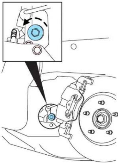
If this is the first check of the transmission fluid, it may be necessary to remove the perforated section of the splash shield (as indicated on the splash shield).

- Be sure the engine has been stopped for at least 3 minutes before performing the fluid level check.
Maintenance and Specifications
- The fluid level should be within 1/4 inch (6 mm) of the plug threads.
- Replace the check plug.

AdjustingeCVTfluidlevels
Before adding any fluid, make sure the correct type is used. The type of fluid used is indicated in the Maintenanceproductspecificationsand capacitiessection in this chapter.
Useofanon-approvedfluidmaycauseinternaltransaxle componentdamage.
If the fluid level is low, add fluid through the check port until the level is correct and fluid begins to run out of the transmission. If an overfill occurs, excess fluid should be removed by allowing the fluid to run out of the check port.
Aseriousouverfillconditionoftransmissionfluidmaycause damage.
Do not use supplemental transmission fluid additives, treatments or cleaning agents. The use of these materials may affect transmission operation and result in damage to internal transmission components.
AIR FILTER
Refer to scheduled maintenance information for the appropriate intervals for changing the air filter element.
When changing the air filter element, use only the Motorcraft air filter element listed. Refer to Motorcraftpartnumbers in this chapter.

To reduce the risk of vehicle damage and/or personal burn injuries do not start your engine with the air cleaner removed to not remove it while the engine is running.
Maintenance and Specifications
Changing the air filter element
-
Release the clamps that secure the air filter housing cover.
-
Carefully separate the two halves of the air filter housing.
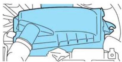
-
Remove the air filter element from the air filter housing.
-
Wipe the air filter housing and cover clean to remove any dirt or debris and to ensure good sealing.
-
Install a new air filter element. Be careful not to crimp the filter element edges between the air filter housing and cover. This could cause filter damage and allow unfiltered air to enter the engine if not properly seated.

- Replace the air filter housing cover and secure the clamps.
Note: Failure to use the correct air filter element may result in severe engine damage. The customer warranty may be voided for any damage to the engine if the correct air filter element is not used.
HIGH VOLTAGE BATTERY COOLING FILTER (REAR A/C) MAINTENANCE
The high voltage battery has a dedicated A/C cooling system which includes an air filter.
Refer to the scheduled maintenance information for the appropriate intervals for air filter.
When changing the air filter element, use only the Motorcraft air filter element listed. Refer to Motorcraftpartnumbers in this chapter.
Maintenance and Specifications
Changing the high voltage battery air filter element
- Remove access panel located in the rear cargo area on the driver's side trim panel to expose the filter cover.

- Push the tabs (located on each side of filter cover) while pulling gently to remove filter cover.

- Install new filter and filter cover (note arrows indicating top side).
- Re-install the access panel into the trim panel.
Maintenance and Specifications
MOTORCRAFT PART NUMBERS
| Component2.3LI4engine | |
| Oil filter FL-2017-B | 1 |
| PCV valve | 2 |
| Spark plugs | 3 |
| Engine air filter element FA-1772 | 4 |
| Rear A/C (high voltage battery cooling) air filter element | FP-51 |
| Cabin air filter FP-66 | |
| Fuel filter FG-872 | |
| Low voltage (underhood) battery BX | T-96R |
1 When changing oil filter you must also replace the filter cap O-ring. The oil filter drain plug O-ring must also be replaced whenever the oil filter drain plug is removed. Reuse of the O-rings may cause engine oil leakage and may result in severe engine damage. The customer warranty may be void for any damage to the engine if the O-rings are not replaced.
2 The PCV valve is a critical emission component. It is one of the items listed in scheduled maintenance information chapter and is essential to the life and performance of your vehicle and to its emissions system.
For PCV valve replacement, see your authorized dealer. Refer to scheduled maintenance information chapter for the appropriate intervals for changing the PCV valve.
Replace the PCV valvewithonethatmeets Fordmaterialanddesign specifications for your vehicle, such as a Motorcraft to equivalent replacement part. The customer warranty may be void for any damage to the emission system if such a PCV valve is not used.
3 For spark plug replacement, see your authorized dealer. Refer to scheduled maintenance information chapter for the appropriate intervals for changing the spark plugs.
ReplacethsparkplugswithonesthatmeetFordmaterialand designspecificationsforyourvehicle,suchasMotorcraftorequivalentreplacementparts.Thecustomerwarrantymaybevoid foranydamagetotheengineifsuchsparkplugsarenotused.
4 Failure to use the correct air filter element may result in severe engine damage. The customer warranty may be void for any damage to the engine if the correct air filter element is not used.
MAINTENANCE PRODUCT SPECIFICATIONS AND CAPACITIES
| ItemCapacity | FordPartNameorequivalent | FordPartNumber/FordSpecification | |
| Brake fluid | Between MIN and MAX lines on reservoir | Motorcraft High Performance DOT 3 Motor Vehicle Brake Fluid | PM-1-C / WSS-M6C62-A |
| Body hinges, latches, door striker plates and rollers, seat tracks, fuel filler door hinge and spring, primary and auxiliary hood latches | — Multi-Purpose Grcase | XG-4 or XL-5 / ESB-M1C93-B | |
| Engine coolant 8.5 quarts (8.0L) | Motorcraft Premium Gold Engine Coolant with bittering agent (yellow-colored) 1 | VC-7-B / WSS-M97B51-A1 | |
| Motor/Electronics (M/E) Coolant | 3.7 quarts (3.5L) | ||
| Cooling system stop leak pellets | — | Motorcraft Cooling System Stop Leak Pellets | VC-6 / WSS-M99B37-B6 |
| Engine oil 4.5 quarts (4.25L) | Motorcraft SAE 5W-20 Premium Synthetic Blend Motor Oil (US) Motorcraft SAE 5W-20 Super Premium Motor Oil (Canada) 2 | XO-5W20-QSP (US) CXO-5W20-LSP12 (Canada) / WSS-M2C930-A with API Certification Mark | |
Maintenance and Specifications
| ItemCapacity | FordPartNameor equivalent | FordPartNumber/ FordSpecification | |
| Automatic eCVT transaxle fluid | 5.3 quarts (5.0L) 3 | Motorcraft MERCON®V ATF 4 | XT-5-QM / MERCON®V |
| Rear axle fluid (4WD) 2.96 pints (1.4L) 5 | Motorcraft SAE 80W-90 Premium Rear Axle Lubricant 6 | XY-80W90-QL / WSP-M2C197-A | |
| Power Transfer Unit fluid (4WD) 7 | 12 ounces (0.35L) | Motorcraft SAE 75W-140 Rear Axle Lubricant | XY-75W140-QL / WSL-M2C192-A |
| Windshield washer fluid 2.7 quarts (2.6L) | Motorcraft Premium Windshield Washer Concentrate | ZC-32-A / WSB-M8B16-A2 | |
| Fuel tank 15 gallons (56.8L) — — | |||
Add the coolant type originally equipped in your vehicle. Refer to Adding engine coolant in this chapter.
2 Use of synthetic or synthetic blend motor oil is not mandatory. Engine oil need only meet the
requirements of Ford specification WSS-M2C930-A and the API Certification mark.
3 Indicates only approximate dry-fill capacity.
4 Using any transmission fluid other than those that meet the recommended specification may cause
internal transaxle damage. Do not use Motorcraft MERCON®CVT (blue) ATF. This vehicle uses
only Motorcraft MERCON®VATF
5 Fill to 1/4 inch to 9/16 inch (6 mm to 14 mm) below bottom of fill hole.
6 4WD vehicles exposed for prolonged periods to temperatures less than -40° C ( -40° F) should
change out the rear axle fluid to Motorcraft SAE 75W-140 Re
XY-75W140-QL meeting Ford specification WSL-M2C192-A.
7 The Power Transfer Unit is lubricated for life with synthetic lube. Lubricant levels are not to be
checked or changed unless a leak is suspected or repair required. Replace Power Transfer Unit
lubricant with specified synthetic lubricant anytime the unit is submerged in water.
Maintenance and Specifications
ENGINE DATA
| Engine2.3LI4engine | |
| Cubic inches 140 | |
| Required fuel 87 octane | |
| Firing order 1-3-4-2 | |
| Ignition system Coil on plug | |
| Spark plug gap 0.049–0.053 inch (1.25–1.35mm) | |
| Compression ratio 12.3:1 | |
Engine drivebelt routing
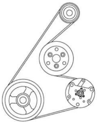
•2.3L I4 Engine
HIGH VOLTAGE BATTERY DATA
| HighVoltageBattery | |
| Battery chemistry Nickel Metal Hydride | |
| Nominal Voltage 330 Volts | |
| Capacity 6 Amp-hours | |
Maintenance and Specifications
IDENTIFYING YOUR VEHICLE
Safety Compliance Certification Label
The National Highway Traffic Safety Administration Regulations require that a Safety Compliance Certification Label be affixed to a vehicle and prescribe where the Safety Compliance Certification Label may be located. The Safety Compliance Certification Label is located on the structure (B-Pillar) by the trailing edge of the driver's door or the edge of the driver's door.
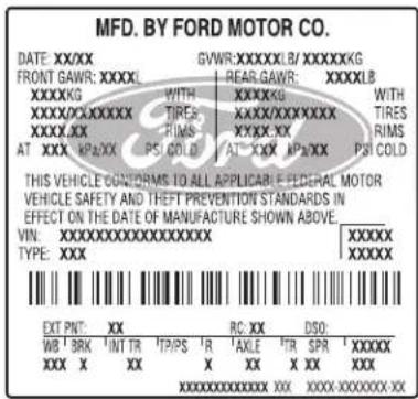
Vehicle identification number (VIN)
The vehicle identification number is located on the driver side instrument panel.
Please note that in the graphic, XXXX is representative of your vehicle identification number.

2008EscapeHybrid(ehv) OwnersGuide(post-2002-fmt) USA(fus)
Maintenance and Specifications
The Vehicle Identification Number (VIN) contains the following information:
- World manufacturer identifier
- Brake system / Gross Vehicle Weight Rating (GVWR) / Restraint System
- Vehicle line, series, body type
- Engine type
- Check digit
- Model year
- Assembly plant
- Production sequence number

TRANSMISSION/TRANSAXLE CODE DESIGNATIONS
You can find a transmission/transaxle code on the Safety Compliance Certification Label. The following table tells you which transmission or transaxle each code represents.

| DescriptionCode | |
| Electronically controlled continuously variable transmission, eCVT | H |
Accessories
GENUINE FORD ACCESSORIES FOR YOUR VEHICLE
A wide selection of Genuine Ford Accessories are available for your vehicle through your local Ford or Ford of Canada dealer. These quality accessories have been specifically engineered to fulfill your automotive needs; they are custom designed to complement the style and aerodynamic appearance of your vehicle. In addition, each accessory is made from high quality materials and meets or exceeds Ford's rigorous engineering and safety specifications. Ford Motor Company will repair or replace any properly dealer-installed Genuine Ford Accessories found to be defective in factory-supplied materials or workmanship during the warranty period, as well as any component damaged by the defective accessories. The accessories will be warranted for whichever provides you the greatest benefit:
- 12 months or 12,000 miles (20,000 km) (whichever occurs first), or
- the remainder of your new vehicle limited warranty.
Contact your dealer for details and a copy of the warranty.
The following is a list of several Genuine Ford Accessories. Not all accessories are available for all models. For a complete listing of the accessories that are available for your vehicle, please contact your dealer or visit our online store at: www.fordaccessoriesstore.com.
Exterior style
Bug shields
Deflectors
Splash guards
Interior style
Floor mats
Lifestyle
Ash cup / smoker's package
Cargo management accessories
Cross bars
Peace of mind
Wheel locks
288
2008EscapeHybrid(ehv)
OwnersGuide(post-2002-fmt)
USA(fus)
Accessories
Not all accessories are available for all models.
For maximum vehicle performance, keep the following information in mind when adding accessories or equipment to your vehicle:
- When adding accessories, equipment, passengers and luggage to your vehicle, do not exceed the total weight capacity of the vehicle or of the front or rear axle (GVWR or GAWR as indicated on the Safety Compliance Certification label). Consult your authorized dealer for specific weight information.
- The Federal Communications Commission (FCC) and Canadian Radio Telecommunications Commission (CRTC) regulate the use of mobile communications systems — such as two-way radios, telephones and theft alarms - that are equipped with radio transmitters. Any such equipment installed in your vehicle should comply with FCC or CRTC regulations and should be installed only by a qualified service technician.
- Mobile communications systems may harm the operation of your vehicle, particularly if they are not properly designed for automotive use.
- To avoid interference with other vehicle functions, such as anti-lock braking systems, amateur radio users who install radios and antennas onto their vehicle should not locate the Amateur Radio Antennas in the area of the driver's side hood.
- Electrical or electronic accessories or components that are added to the vehicle by the authorized dealer or the owner may adversely affect battery performance and durability.
Scheduled Maintenance Guide
GENERAL MAINTENANCE INFORMATION
Why maintain your vehicle?
This guide describes the scheduled maintenance required for your vehicle. Carefully following this schedule helps protect against major repair expenses resulting from neglect or inadequate maintenance and may also help to increase the value of your vehicle when you sell or trade it.
It is your responsibility to see that all scheduled maintenance is performed and that the materials used meet Ford engineering specifications. Failure to perform scheduled maintenance specific in this guide will invalidate warranty coverage on parts affected by the lack of maintenance. Be sure receipts for completed maintenance are kept with the vehicle and confirmation of the work performed is always recorded in this guide.
Your Ford or Lincoln Mercury dealer, or Ford or Lincoln Mercury Quality Care Center has factory trained technicians who can perform the required maintenance using genuine Ford parts. They are committed to meeting your service needs and to assuring your continuing satisfaction.
Protecting your investment
Maintenance is an investment that will pay dividends in the form of improved reliability, durability and resale value. To ensure the proper performance of your vehicle and its emission control systems, it is imperative that scheduled maintenance be completed at the designated intervals.
Your vehicle is very sophisticated and built with multiple complex performance systems. Every manufacturer develops these systems using different specifications and performance features. That's why it's important to rely upon your Ford or Lincoln Mercury dealership to properly diagnose and repair your vehicle.
Ford Motor Company has recommended maintenance intervals for various parts and component systems based upon engineering testing. Ford Motor Company relies upon this testing to determine the most appropriate mileage for replacement of oils and fluids to protect your vehicle at the lowest overall cost to you and recommends against maintenance schedules that deviate from the scheduled maintenance information.
Scheduled Maintenance Guide
Ford strongly recommends the use of genuine Ford replacement parts. Parts other than Ford, Motorcraft or Ford authorized remanufactured parts that are used for maintenance replacement or for the service of components affecting emission control must be equivalent to genuine Ford Motor Company parts in performance and durability. It is the owner's responsibility to determine the equivalency of such parts. Please consult your WarrantyGuide for complete warranty information.
Non-Ford approved chemicals or additives are not required for factory recommended maintenance. In fact, Ford Motor Company recommends against the use of such additive products unless specifically recommended by Ford for a particular application.
Oil, fluids and flushing
In many cases, fluid discoloration is a normal operating characteristic and, by itself, does not necessarily indicate a concern or that the fluid needs to be changed. However, discolored fluids that also show signs of overheating and/or foreign material contamination should be inspected immediately by a qualified expert such as the factory-trained technicians at your Ford or Lincoln Mercury Dealership. Your vehicle's oils and fluids should be changed at the specified intervals or in conjunction with a repair. Flushing is a viable way to change fluid for many vehicle sub-systems during scheduled maintenance. It is critical that systems are flushed only with new fluid that is the same as that required to fill and operate the system, or using a Ford-approved flushing chemical.
EngineEmissionslabel
Emissions information appears on the Engine Emissions label on the underside of the hood. This decal identifies engine displacement and provides certain engine specifications.
Any modification of the emissions control system could create liability under federal law (U.S.) if made prior to sale and registration, under the laws of some states if made thereafter. Further, federal law prohibits vehicle manufacturers, dealers and other persons engaged in the business of repairing, servicing, selling, leasing or trading motor vehicles as well as fleet operations from knowingly removing or rendering an emissions control system inoperative after sale and delivery to an ultimate purchaser. In Canada, modifications of the emissions control system could create liability under applicable federal or provincial laws.
Genuine Ford Parts and Service
When planning your maintenance services, consider your Ford and Lincoln Mercury dealership for all your vehicle's needs.
Scheduled Maintenance Guide
Getthemostfromyourserviceandmaintenancevisits
There are a lot of reasons why visiting your Ford or Lincoln Mercury Dealership for all your service needs is a great way to help keep your vehicle running great.
Convenience
Many Dealerships have extended evening and Saturday hours to make your service visit more convenient. How's that for quality service?
Factory-trainedTechnicians
Ford and Lincoln Mercury service technicians participate in extensive factory-sponsored certification training to help them become experts on the operation of your vehicle. Ask your Dealership about the training and certification their technicians have received.
FactoryAuthorizedSystemsChecks
In the event your vehicle experiences a component related concern, please contact your Ford, Lincoln or Mercury dealership. The Ford Motor Company Trained Technicians who work at Ford, Lincoln or Mercury dealerships are specifically trained to understand your vehicle.
A proper repair begins with a thorough system check. Factory Authorized Systems Checks can ONLY be found at a Ford or Lincoln Mercury dealership. In some circumstances, the Technician may need to request your authorization to perform additional operations to determine the final diagnosis. The Technician's goal is to ensure that your vehicle is fixed right the first time, at the best value to you.
The following list represents several of the Factory Authorized Systems Checks available at participating Ford and Lincoln Mercury Dealerships:
- Climate Control
- Check Engine Light
- All Wheel Drive/Four-Wheel Drive
• Automatic Transmission
•Engine Cooling/Cabin Heating - Suspension/Steering
- Charge/Start/Battery
- Wheel Alignment
- Brakes
And when your vehicle needs replacement parts, insist that only parts meeting Ford Motor Company's specifications are used. Genuine Ford
Scheduled Maintenance Guide
and Motorcraft branded parts meet these specifications. You can find them at your Ford and Lincoln Mercury Dealership. Look for the following brand logos to ensure the parts installed on your vehicle meet Ford Motor Company Specifications.
GenuineFordandMotorcraftReplacementParts
Ford and Lincoln Mercury dealerships stock Ford and Motorcraft branded replacement parts. These parts meet or exceed Ford Motor Company's specifications, and we stand behind them. Maintenance parts installed at your Ford or Lincoln Mercury dealership carry a nationwide, 12 months, 12,000 mile parts and labor limited warranty. Your dealer can give you details.
ValueShoppingforYourVehicle'sMaintenanceNeeds
Your dealership recognizes the competitive landscape of maintenance and light repair automotive services. With factory-trained technicians, and one-stop service from routine maintenance like oil changes and tire rotations to repairs like brake service, check out the value your Ford and Lincoln Mercury dealers can offer.
WHICH MAINTENANCE SCHEDULE SHOULD YOU FOLLOW?
Owner Checks and Services
RefertoMileageIntervalsforAdditionalChecksandServices
Certain basic maintenance checks and inspections should be performed by the owner or a service technician at the intervals indicated. Service information and supporting specifications are provided in this Owner's Guide.
Any adverse condition should be brought to the attention of your dealer or qualified service technician as soon as possible for the proper service advice. The owner maintenance service checks are generally not covered by warranties so you may be charged for labor, parts or lubricants used.
MaximumOilChangelInterval
12months, 10,000miles (16,000km) or 200hoursofengineoperation.
MotorcraftPremiumGoldEngineCoolantchangeinterval
6yearsor100,000miles(160,000km)-changeMotorcraftPremiumGoldEngineCoolant(whichevercomesfirst) After initial change-changeMotorcraftPremiumGoldEngineCoolantevery3yearsor50,000miles(80,000km).
Scheduled Maintenance Guide
Checkeverymonth
☐ Checkfunctionofallinteriorandexteriorlights
□ Checkfiresforwearandcorrectairpressure,includingsparetire
Checkwindshieldwasherfluidlevel
□ Checkengineoillevel
Check every six months
☐ Checklap/shoulderbeltsandseatlatchesforwearandfunction
☐ Checkthatexternallymountedsparetireisproperlystowed(tight)
☐ Checkparkingbrakeforproperoperation
☐ Checksafetywaminglamps(brake,ABS,airbag,safetybelt)foroperation
□ Checkcoolingsystemfluidlevelandcoolantstrength
☐ Checklowvoltage(underhood)batteryconnectionsandcleanifnecessary
☐ Checkwasherspray, wiperoperation and clean all wiper blades (replace as necessary)
Checkandlubricateallhinges,latchesandoutsidelocks.Inspectforcorrectoperation
☐ Checkandlubricatedoorrubberweatherstrips.Inspectforexcessivewear
Checkandcleanbodyanddoordrainholes.Inspectforclogsandobstructions
Multi-point Inspection
In order to keep your vehicle running right, it is important that you have the systems on your vehicle checked regularly. This can help identify any potential issue before there are any problems. Ford Motor Company suggests the following multi-point inspection to be performed at every scheduled maintenance as the way to ensure your vehicle keeps running right.
Multi-pointinspection-Recommendedateveryvisit
☐ Checkandtopupfluidlevels:brake,enginecoolantrecoveryreservoir,motor/electronicsreservoirandwindowwasher.
□ Inspecttiresforwearandcorrectairpressure.
☐ Checkexhaustsystemforleaks,damage,loosepartsandforeignmaterials.
☐ Checklowvoltage(underhood)batteryperformance.
☐ Checkoperationofhorn,exteriorlamps,turnsignalsandhazardwarninglights.
☐ Checkradiator, coolers and heater and air conditioning hoses.
□ Inspectwindshieldwashersprayandwiperoperation.
☐ Checkwindshieldforcracks, chipsandpitting.
Inspectforoilandfluidleaks.
Inspectengineaircleanerfilterandelements.
Inspecthalf-shaftdustboots.
☐ Checkshocks, strutsandothersuspensioncomponentsforleaksanddamage.
Scheduled Maintenance Guide
NORMAL SCHEDULED MAINTENANCE AND LOG
The following section contains the “Normal Schedule”. This schedule is presented at specific mileage (kilometer) intervals with exceptions noted.
ADDITIONAL INFORMATION AVAILABLE ON THE WEB
To learn more about the importance of routine and dealer-performed maintenance on your vehicle, please visit the Ford Customer Service Web site. You'll also find important warranty information, customer assistance, technical expertise, frequently asked questions and much more. The Web site location is: www.genuineservice.com.
Then go to the vehicles and services pick at the Web site.
U.S. AND CANADIAN SCHEDULE


Scheduled Maintenance Guide
20,000miles(32,000km)
| ChangeengineoilandreplaceoilfilterInspecttiresforwearandmeasuretreaddepthRotatetiresInspectbrakepads,shoes,rotors,drums,brakelinesandhosesandparkingbrakeInspectengineandMotor/electronicscoolingsystemandhosesInspectsteeringlinkage,suspensionand,ifequipped,half-shafts,driveshaftandballjointsInspectexhaustsystemandheatshieldsReplacehighvoltagebatteryA/Cfilter | DEALER VALIDATION:RO#: P&AC ODE:DATE: M ILEAGE: |
30,000miles(48,000km)
| ☐ Changeengineoilandreplaceoilfilter☐ Inspecttiresforwearandmeasuretreaddepth☐ Rotatetires☐ InspecthighvoltagebatteryA/Cfilter,replaceifnecessary☐ Replaceengineairfilter | ||
| DEALER VALIDATION: | ||
| RO#: P&A C | ODE: | |
| DATE: M | ILEAGE: | |
40,000miles(64,000km)
| ChangeengineoilandreplaceoilfilterInspecttiresforwearandmeasuretreaddepthRotatetiresInspectbrakepads,shoes,rotors,drums,brakelinesand hosesandparkingbrakeInspectengineandMotor/electronicscoolingsystemand hosesInspectsteeringlinkage,suspensionand,ifequipped,half-shafts,driveshaftandbelljointsInspectexhaustsystemandheatshieldsReplacehighvoltagebatteryA/Cfilter | DEALER VALIDATION:RO#: P&A C ODE:DATE: M ILEAGE: | ||
Scheduled Maintenance Guide
50,000miles(80,000km)
| ChangeengineoilandreplaceoilfilterInspecttiresforwearandmeasuretreaddepthRotatetiresInspecthighvoltagebatteryA/Cfilter,replaceifnecessary | DEALER VALIDATION:RO#: P&A C ODE:DATE: M ILEAGE: | ||
60,000miles(96,000km)
| ChangeengineoilandreplaceoilfilterInspecttiresforwearandmeasuretreaddepthRotatetiresInspectbrakepods,shoes,rotors,drums,brakelinesandhosesandparkingbrakeInspectengineandMotor/electronicscoolingsystemandhosesInspectsteeringlinkage,suspensionand,ifequipped,half-shafts,driveshaftandballjointsInspectexhaustsystemandheatshieldsReplacehighvoltagebatteryA/CfilterReplaceengineairfilter | DEALER VALIDATION:RO#: P&AC ODE:DATE: M ILEAGE: |
70,000miles(112,000km)
| ☐ Changeengineoilandreplaceoilfilter☐ Inspecttiresforwearandmeasuretreaddepth☐ Rotatetires☐ InspecthighvoltagebatteryA/Cfilter,replaceifnecessary | ||
| DEALER VALIDATION: | ||
| RO#: P&A C | ODE: | |
| DATE: M | ILEAGE: | |
Scheduled Maintenance Guide
80,000miles(128,000km)
| ChangeengineoilandreplaceoilfilterInspecttiresforwearandmeasuretreaddepthRotatetiresInspectbrakepads,shoes,rotors,drums,brakelinesandhosesandparkingbrakeInspectengineandMotor/electronicscoolingsystemandhosesInspectsteeringlinkage,suspensionand,ifequipped,half-shafts,driveshaftandballjointsInspectexhaustsystemandheatshieldsReplacehighvoltagebatteryA/Cfilter | DEALER VALIDATION:RO#: P&A C ODE:DATE: M ILEAGE: |
90,000miles(144,000km)
| ☐ Changeengineoilandreplaceoilfilter☐ Inspecttiresforwearandmeasuretreaddepth☐ Rotatetires☐ InspecthighvoltagebatteryA/Cfilter,replaceifnecessary☐ Replaceengineairfilter | ||
| DEALER VALIDATION: | ||
| RO#: P&A C | ODE: | |
| DATE: M | ILEAGE: | |
100,000miles(160,000km)
| ChangeengineoilandreplaceoilfilterInspecttiresforwearandmeasuretreaddepthRotatetiresInspectbrakepads,shoes,rators,drums,brakelinesandhosesandparkingbrakeInspectengineandMotor/electronicscoolingsystemandhosesInspectsteeringlinkage,suspensionand,ifequipped,half-shafts,driveshaftandballjointsInspectexhaustsystemandheatshieldsReplacehighvoltagebatteryA/CfilterReplacefuelfilterReplaceenginecoolantandMotor/electronicscoolant (seeMotorcraftPremiumGoldCoolantChangeRecord)InspectaccessorydrivebeltReplacesparkplugs | DEALER VALIDATION:RO#: P&A C ODE:DATE: M ILEAGE: |
Scheduled Maintenance Guide
110,000miles(176,000km)
| ☐ Changeengineoilandreplaceoilfilter☐ Inspecttiresforwearandmeasuretreaddepth☐ Rotatetires☐ InspecthighvoltagebatteryA/Cfilter,replaceifnecessary | ||
| DEALER VALIDATION: | ||
| RO#: P&A C | ODE: | |
| DATE: M | ILEAGE: | |
120,000miles(192,000km)
| ChangeengineoilandreplaceoilfilterInspecttiresforwearandmeasuretreaddepthRotatetiresInspectbrakepods,shoes,rotors,drums,brakelinesandhosesandparkingbrakeInspectengineandMotor/electronicscoolingsystemandhosesInspectsteeringlinkage,suspensionand,ifequipped,half-shafts,driveshaftandballjointsInspectexhaustsystemandheatshieldsReplacehighvoltagebatteryA/CfilterReplaceengineairfilter | DEALER VALIDATION:RO#: P&AC ODE:DATE: M ILEAGE: |
130,000miles(208,000km)
| ☐ Changeengineoilandreplaceoilfilter☐ Inspecttiresforwearandmeasuretreaddepth☐ Rotatetires☐ InspecthighvoltagebatteryA/Cfilter,replaceifnecessary | ||
| DEALER VALIDATION: | ||
| RO#: P&A C | ODE: | |
| DATE: M | ILEAGE: | |
Scheduled Maintenance Guide
140,000miles(224,000km)
| ChangeengineoilandreplaceoilfilterInspecttiresforwearandmeasuretreaddepthRotatetiresInspectbrakepads,shoes,rotors,drums,brakelinesandhosesandparkingbrakeInspectengineandMotor/electronicscoolingsystemandhosesInspectsteeringlinkage,suspensionand,ifequipped,half-shafts,driveshaftandballjointsInspectexhaustsystemandheatshieldsReplacehighvoltagebatteryA/Cfilter | DEALER VALIDATION:RO#: P&A C ODE:DATE: M ILEAGE: |
150,000miles(240,000km)
| ChangeengineoilandreplaceoilfilterInspecttiresforwearandmeasuretreaddepthRotatetiresInspecthighvoltagebatteryA/CfilterReplaceengineairfilterReplaceenginecoolantandMotor/electronicscoolant(seeMatorcraftPremiumGoldCoolantChangeRecord)Replaceaccessorydrivebelt(ifnotreplacedinthelast100,000miles)InspectPCVvalveforflowandreplace,ifrequiredReplacerearaxlelubricant(4WDvehiclesonly) | DEALER VALIDATION:RO#: P&A C ODE:DATE: M ILEAGE: |
Scheduled Maintenance Guide
SPECIAL OPERATING CONDITIONS
Towingatrailerorusingacamperorcar-topcarrier
Every5,000miles,6monthsor
Changeengineoilandreplacefilter
200hoursofengineoperation
(whichevercomesfirst)
Every5,000milesInspecttiresandrotate
ExtensiveIdlingand/orLowSpeedDrivingforLongDistancesasinHeavy CommercialUseSuchasDelivery, Taxi, PatrolVehicleorLivery.This operatingconditionisforExtensiveMaximumA/CorHeaterOperation withengineonintheabovelistedusage.
Every5,000miles,6monthsor
Changeengineoilandreplacefilter
200hoursofengineoperation
(whichevercomesfirst)
Every5,000milesInspecttiresandrotate
Every60,000milesReplacesparkplugs
AsrequiredReplacecabinairfilter, ifequipped
Operating industry conditions such as unpaved or dysty roads
Every5,000miles,6monthsor
Changeengineoilandreplacefilter
200hoursofengineoperation
(whichevercomesfirst)
Inspecttiresandrotate
AsrequiredReplacecabinairfilter, ifequipped
Replaceengineairfilter
ReplacehighvoltagebatteryA/Cairfilter
Off-roadoperation
Every5,000miles,6monthsor
Changeengineoilandreplacefilter
200hoursofengineoperation
(whichevercomesfirst)
Inspecttiresandrotate
AsrequiredReplacecabinairfilter, ifequipped
Replaceengineairfilter
ReplacehighvoltagebatteryA/Cfilter
Scheduled Maintenance Guide
Special Operating Conditions Log
| DEALER VALIDATION:RO#: P&A CODE:DATE: M ILEAGE: | DEALER VALIDATION:RO#: P&A CODE:DATE: M ILEAGE: |
| DEALER VALIDATION:RO#: P&A CODE:DATE: M ILEAGE: | DEALER VALIDATION:RO#: P&A CODE:DATE: M ILEAGE: |
| DEALER VALIDATION:RO#: P&A CODE:DATE: M ILEAGE: | DEALER VALIDATION:RO#: P&A CODE:DATE: M ILEAGE: |
| DEALER VALIDATION:RO#: P&A CODE:DATE: M ILEAGE: | |
| DEALER VALIDATION:RO#: P&A CODE:DATE: M ILEAGE: | DEALER VALIDATION:RO#: P&A CODE:DATE: M ILEAGE: |
Scheduled Maintenance Guide
Special Operating Conditions Log
| DEALER VALIDATION:RO#: P&A CODE:DATE: M ILEAGE: | DEALER VALIDATION:RO#: P&A CODE:DATE: M ILEAGE: |
| DEALER VALIDATION:RO#: P&A CODE:DATE: M ILEAGE: | DEALER VALIDATION:RO#: P&A CODE:DATE: M ILEAGE: |
| DEALER VALIDATION:RO#: P&A CODE:DATE: M ILEAGE: | DEALER VALIDATION:RO#: P&A CODE:DATE: M ILEAGE: |
| DEALER VALIDATION:RO#: P&A CODE:DATE: M ILEAGE: | |
| DEALER VALIDATION:RO#: P&A CODE:DATE: M ILEAGE: | DEALER VALIDATION:RO#: P&A CODE:DATE: M ILEAGE: |
Scheduled Maintenance Guide
| 6yearsor 100,000miles (160,000km) (whichevercomesfirst)-changeMotorcraftPremiumGoldEngineCoolantand motor/electricalcoolant. |
| Afterinitialchange-changeMotorcraftPremiumGoldEngineCoolantevery3yearsor 50,000miles (80,000km) |
| Currentmileagegoeshere=>Add50,000milestothecurrentmiles+50,000Nextchangedueatthismileage=>OrToday'sdategoeshere=>A d d 3 y e a r s + 0 0 / 0 0 / 0 3Dateofnextchange=>whichevercomesfirst | DealerStampP&ACODER.O.# |
| Currentmileagegoeshere=>Add50,000milestothecurrentmiles+50,000Nextchangedueatthismileage=>OrToday'sdategoeshere=>A d d 3 y e a r s + 0 0 / 0 0 / 0 3Dateofnextchange=>whichevercomesfirst | DealerStampP&ACODER.O.# |
| Currentmileagegoeshere=>Add50,000milestothecurrentmiles+50,000Nextchangedueatthismileage=>OrToday'sdategoeshere=>A d d 3 y e a r s + 0 0 / 0 0 / 0 3Dateofnextchange=>whichevercomesfirst | DealerStampP&ACODER.O.# |
Scheduled Maintenance Guide
| Currentmileagegoeshere=>Add50,000milestothecurrentmiles+50,000Nextchangedueatthismileage=>OrToday'sdategoeshere=>A d d 3 y e a r s + 0 0 / 0 0 / 0 3Dateofnextchange=>whichevercomesfirst | DealerStampP&ACODER.O.# |
Index
A
Accessory delay 61
Air cleaner filter .....279–282
Air conditioning
automatic temperature control system ....39
Airbag supplemental
restraint system .....119, 128, 131
and child safety seats .....121
description .....119, 128, 131
disposal 134
driver airbag .....121, 129, 132
indicator light ......128, 130, 134
operation ......121, 129, 132
passenger airbag .....121, 129, 132
side airbag 128
All Wheel Drive (AWD),
driving off road 195
Ambulance packages .....15
Anti-lock brake system
(see Brakes)....185
Anti-theft system 93
Audio system (see Radio) .....25
Automatic transaxle
fluid, adding 277
fluid, checking 277
Automatic transmission
driving an automatic
overdrive ....191
fluid, refill capacities .....283
fluid, specification .....283
Auxiliary Input Jack ....32
Auxiliary power point ....57
Axle
lubricant specifications .....283
refill capacities ....283
B
Battery 257
acid, treating emergencies .....257
jumping a disabled battery ....224, 228
maintenance-free 257
replacement, specifications ...282
servicing 257
Belt-Minder ......114
Booster seats 135
Brakes 184–185
anti-lock 185
anti-lock brake system
(ABS) warning light .....186
fluid, checking and adding ....276
fluid, refill capacities .....283
fluid, specifications .....283
lubricant specifications .....283
parking 187
shift interlock 189
Bulbs 49
C
Capacities for refilling fluids ....283
Cargo area shade ....78
Cell phone use ....15
Child safety restraints .....135
child safety belts ....135
Child safety seats 138
attaching with tether straps ..142
in front seat 139
in rear seat 139
Child safety seats - booster
seats 135
Cleaning your vehicle
engine compartment .....243
instrument panel 245
Index
interior 245
plastic parts ......244
washing 241
waxing 242
wheels 242
wiper blades 244
Climate control (see Air
conditioning or Heating) .....39
Compass, electronic 62
calibration 63
set zone adjustment .....62
Console 56
Controls
power seat 98
steering column 67
Coolant
checking and adding .....260–261
refill capacities ......264, 283
specifications 283
Cruise control
(see Speed control) 64
Customer Assistance ......202
Ford Extended Service
Plan 237
Getting assistance outside
the U.S. and Canada .....238
Getting roadside assistance ...202
Getting the service
you need 233
Ordering additional
owner's literature 239
Utilizing the Mediation/
Arbitration Program ......237
D
Daytime running lamps
(see Lamps) 45
Dipstick
automatic transmission
fluid 277
engine oil 254
Driving under special
conditions ......192, 196, 199
sand 197
snow and ice 200
through water ......198, 201
E
Electronic message center .....69
Emergencies, roadside
jump-starting ......224, 228
Emission control system .....273
Engine 285
cleaning 243
idle speed control ......257
lubrication specifications .....283
refill capacities 283
service points ......251
Engine block heater .....184
Engine oil 254
checking and adding .....254
dipstick 254
filter, specifications .....256, 282
recommendations ......256
refill capacities 283
specifications 283
Exhaust fumes 184
F
Fluid capacities ....283
Foglamps 44
Four-Wheel Drive vehicles
driving off road 195
Index
preparing to drive your
vehicle 188
Fuel 265
calculating fuel
economy 70,270
cap 267
capacity 283
choosing the right fuel .....268
comparisons with EPA
fuel economy estimates .....273
detergent in fuel 270
filling your vehicle
with fuel 265, 267, 270
filter, specifications .....265, 282
fuel pump/high voltage
shut-off switches .....204
improving fuel economy .....270
octane rating 269, 285
quality 269
running out of fuel 270
safety information relating
to automotive fuels ....265
Fuses 206-207
G
Gas cap (see Fuel cap) .....267
Gas mileage
(see Fuel economy) ......270
Gauges 23
H
Hazard flashers ......204
Head restraints .....97, 100
Headlamps 43
aiming 46
bulb specifications .....49
daytime running lights .....45
flash to pass 45
308
high beam 45
replacing bulbs ....50
turning on and off ....43
Heating
heating and air conditioning system ....39
Hood 250
I
Ignition 181,285
Illuminated visor mirror .....56
Infant seats
(see Safety seats)....138
Inspection/maintenance
(I/M) testing 275
Instrument panel
cleaning 245
cluster 18
lighting up panel and
interior 46
J
Jump-starting your
vehicle 224, 228
K
Keyless entry system
autolock 84, 86
Keys 82,95
positions of the ignition .....181
L
Lamps
bulb replacement
specifications chart .....49
daytime running light ....45
Index
fog lamps 44
headlamps 43
headlamps, flash to pass .....45
instrument panel, dimming .....46
interior lamps ....47–48, 50
replacing bulbs ....50
Lane change indicator
(see Turn signal) 47
Liftgate 77,90
Lights, warning and indicator ....18
anti-lock brakes (ABS) .....186
Load limits 169
Loading instructions .....175
Locks
autolock 84, 86
childproof 88
doors 84
Lubricant specifications .....283
Lug nuts 223
Luggage rack 79
M
Manual transmission
fluid capacities 283
lubricant specifications .....283
Message center 69
english/metric button .....73
system check button .....72
warning messages .....74
Mirrors 61, 64
automatic dimming
rearview mirror 61
fold away 64
heated 64
side view mirrors (power) .....64
Moon roof 68
Motorcraft parts .....247, 265, 282
N
Navigation system ....38
0
Octane rating 269
Oil (see Engine oil) ......254
P
Parking brake ....187
Parts (see Motorcraft parts) ....282
Passenger Occupant
Classification Sensor ....107
Power distribution box
(see Fuses) 210
Power door locks ....84
Power mirrors 64
Power point ....57
Power steering ....188
Power Windows 60
Preparing to drive your
vehicle 188
R
Radio 25
Relays 206
Remote entry system .....88–89
illuminated entry 92
locking/unlocking doors .....89–90
opening the trunk .....90
panic alarm 90
replacement/additional
transmitters 91
replacing the batteries .....90
Reverse sensing system .....193
Index
Roadside assistance ....202
Roof rack 79
S
Safety Belt Maintenance .....113
Safety belts (see
Safety restraints) .....105, 109–112
Safety Canopy ......128–129, 131
Safety defects, reporting .....240
Safety restraints .....105, 109–112
Belt-Minder ® 114
extension assembly .....113
for adults 110-112
for children 134-135
Occupant Classification
Sensor 107
safety belt maintenance .....113
warning light and chime .....114
Safety seats for children .....138
Safety Compliance
Certification Label ......286
Satellite Radio Information .....35
Scheduled Maintenance
Guide 290
General Maintenance
Information 290
Normal Scheduled
Maintenance and Log ......295
Special Operating
Conditions 301
What Maintenance Schedule
Should You Follow? ......293
Seats 97
child safety seats ....138
heated 100
SecuriLock passive anti-theft
system 93
Servicing your vehicle .....248
Snowplowing 15
Spark plugs,
specifications ......282, 285
Special notice
ambulance conversions .....15
utility-type vehicles ....15
Specification chart,
lubricants 283
Speed control 64
Starting your vehicle .....181–183
jump starting .....224, 228
Steering wheel
controls 67
tilting 55
T
Tilt steering wheel ....55
Tire Pressure Monitoring
System (TPMS)
Tires, Wheels and Loading ....164
Tires 148-149
alignment 156
care 152
changing 215, 217
checking the pressure .....152
inflating 150
label 163
replacing 154
rotating 157
safety practices ....155
sidewall information ....158
snow tires and chains .....169
spare tire 213, 215
terminology 149
tire grades 149
treadwear 148, 153
Index
Towing 175
recreational towing .....180
trailer towing 175
wrecker 231
Transmission 189
brake-shift interlock (BSI) ....189
fluid, checking and adding (automatic) 277
fluid, refill capacities .....283
lubricant specifications .....283
Trunk 90
Turn signal 47
V
Vehicle Identification Number (VIN) 286
Vehicle loading ....169
Ventilating your vehicle .....184
W
Warning lights (see Lights) .....18
Washer fluid 252
Water, Driving through .....201
Windows
power 60
rear wiper/washer ....55
Windshield washer fluid and
wipers 54
checking and adding fluid .....252
liftgate reservoir .....252
replacing wiper blades ...253–254
Wrecker towing 231
- ENTERTAINMENT SYSTEMS 25
- CLIMATE CONTROLS 39
- LIGHTS 43
- DRIVER CONTROLS 54
- LOCKS AND SECURITY 82
- TABLE OF CONTENTS
- SEATING AND SAFETY RESTRAINTS 97
- TIRES, WHEELS AND LOADING 146
- DRIVING 181
- ROADSIDE EMERGENCIES 202
- CUSTOMER ASSISTANCE 233
- CLEANING 241
- MAINTENANCE AND SPECIFICATIONS 248
- ACCESSORIES 288
- SCHEDULED MAINTENANCE GUIDE 290
- INTRODUCTION
- CALIFORNIAPROPOSITION65WARNING
- PERCHLORATE MATERIAL
- CONGRATULATIONS
- SAFETY AND ENVIRONMENT PROTECTION
- WARNING SYMBOLS IN THIS GUIDE
- WARNING SYMBOLS ON YOUR VEHICLE
- PROTECTING THE ENVIRONMENT
- BREAKING-IN YOUR VEHICLE
- HYBRID OPERATION
- NORMAL VEHICLE OPERATION
- UNIQUE HYBRID OPERATING CHARACTERISTICS
- DRIVING TO OPTIMIZE FUEL ECONOMY
- ADDITIONALTIPS
- SPECIAL NOTICES
- NEW VEHICLE LIMITED WARRANTY
- SPECIAL INSTRUCTIONS
- SERVICE DATA RECORDING
- EVENTDATARECORDING
- NOTICE TO OWNERS OF PICKUP TRUCKS AND UTILITY TYPE VEHICLES
- USING YOUR VEHICLE WITH A SNOWPLOW
- DONOTUSETHISVEHICLEFORSNOWPLOWING
- USING YOUR VEHICLE AS AN AMBULANCE
- DONOTUSETHISVEHICLEASANAMBULANCE
- CELL PHONE USE
- VEHICLESYMBOLGLOSSARY
- INSTRUMENT CLUSTER
- WARNING LIGHTS AND CHIMES
- BRAKESYSTEMWARNINGLIGHT:TO
- ANTI-LOCKBRAKESYSTEM: IF THE
- ENGINEORMOTORELECTRONIC
- ABSACTIVE/TRACTIONCONTROL® ACTIVE(IFEQUIPPED):FLASHES
- LOWTIREPRESSUREWARNING
- THROTTLECONTROL/POWERTRAIN
- GAUGES
- BATTERYGAUGE: PROVIDES INFORMATION ABOUT THE VEHICLE'S ENERGY USAGE
- ENTERTAINMENT SYSTEMS
- AUDIO SYSTEMS
- EJECT:FORASINGLECD
- MEMORYPRESETS:INRADIO
- CLOCK: TO SET THE TIME, PRESS
- SOUND: PRESS REPEATEDLY TO
- INSATELLITERADIOMODE
- SHUFFLE
- LOAD:FORASINGLECD
- CDSLOT:FORASINGLECD
- AUXILIARY INPUT JACK
- REQUIREDEQUIPMENT
- TOPLAYYOURPORTABLEMUSICPLAYERUSINGTHEAUXILIARYINPUTJACK
- TROUBLESHOOTING
- GENERAL AUDIO INFORMATION
- RADIOFREQUENCIES
- RADIORECEPTIONFACTORS
- CD/CDPLAYERCARE
- AUDIOSYSTEMWARRANTYANDSERVICE
- SATELLITE RADIO INFORMATION (IF EQUIPPED)
- NAVIGATION SYSTEM (IF EQUIPPED)
- DUAL AUTOMATIC TEMPERATURE CONTROL
- CLIMATE CONTROLS
- OPERATING TIPS
- FORMAXIMUMCOOLINGPERFORMANCE
- AUTOMATICOPERATION
- MANUALOPERATION
- TOAIDINSIDEWINDOWDEFOGGING/DEMISTINGINCOLDWEATHER
- REAR WINDOW DEFROSTER R
- HEADLAMP CONTROL
- AUTOLAMP CONTROL (IF EQUIPPED)
- LIGHTS
- AUTOLAMPDELAYSYSTEM(IFEQUIPPED)
- FOGLAMP CONTROL (IF EQUIPPED) ≠0
- HIGH BEAMS ≡D
- FLASH TO PASS
- DAYTIME RUNNING LAMPS (DRL) (IF EQUIPPED)
- PANEL DIMMER CONTROL
- AIMING THE HEADLAMPS
- VERTICAL AIM ADJUSTMENT
- TURN SIGNAL CONTROL ⇔
- INTERIOR LAMPS
- DOME LAMPS AND MAP LAMPS
- CARGO AND DOME LAMP
- INTERIORLIGHTINGBATTERYSAVER
- BULB REPLACEMENT
- HEADLAMP CONDENSATION
- USING THE RIGHT BULBS
- REPLACING THE INTERIOR BULBS
- REPLACING EXTERIOR BULBS
- REPLACINGHEADLAMPBULBS
- REPLACINGFRONTPARKINGLAMP/TURNSIGNALBULBS
- REPLACINGFRONTSIDEMARKERBULBS
- REPLACINGTAIL/STOP/TURN/SIDEMARKER/BACKUPLAMPBULBS
- REPLACINGLICENSEPLATELAMPBULBS
- REPLACINGHIGH-MOUNTBRAKELAMPBULBS
- REPLACINGFOGLAMPBULBS(IFEQUIPPED)
- DRIVER CONTROLS
- MULTI-FUNCTION LEVER
- WINDSHIELD WIPER FEATURES (IF EQUIPPED WITH AUTOLAMP FEATURE)
- REAR WINDOW WIPER/WASHER CONTROLS
- TILT STEERING WHEEL
- ILLUMINATED VISOR MIRROR (IF EQUIPPED)
- CENTER CONSOLE
- AUXILIARY POWER POINT (12V)
- CIGAR/CIGARETTELIGHTER(IFEQUIPPED)
- POWER POINT (110 VAC) (IF EQUIPPED)
- INDICATORLIGHTCODE
- POWER WINDOWS
- ONE TOUCH DOWN
- WINDOW LOCK
- ACCESSORYDELAY
- INTERIOR MIRROR
- AUTOMATIC DIMMING REAR VIEW MIRROR (IF EQUIPPED)
- ELECTRONIC COMPASS (IF EQUIPPED)
- COMPASSCALIBRATIONADJUSTMENT
- EXTERIOR MIRRORS
- POWER SIDE VIEW MIRRORS
- FOLD-AWAY MIRRORS
- HEATED OUTSIDE MIRRORS (IF EQUIPPED)
- DONOTREMOVEICEFROMTHE MIRRORSWITHASCRAPEROR
- SPEED CONTROL
- SETTING SPEED CONTROL
- NOTE
- DISENGAGINGSPEEDCONTROL
- RESUMINGASSETSPEED
- INCREASESPEEDWHILEUSINGSPEEDCONTROL
- REDUCINGSPEEDWHILEUSINGSPEEDCONTROL
- TURNINGOFFSPEEDCONTROL
- STEERING WHEEL CONTROLS (IF EQUIPPED)
- RADIO CONTROL FEATURES
- INRADIOMODE
- INCDMODE
- MOON ROOF (IF EQUIPPED)
- MESSAGE CENTER
- CONSTANTMONITOROFVEHICLE
- SELECTABLE FEATURES
- RESET
- INFOMENU
- ODOMETER/TRIPODOMETER
- DISTANCETOEMPTY(DTE)
- AVERAGEFUELECONOMY(AFE)(IFEQUIPPED)
- INSTANTANEOUSFUELECONOMY(IFEQUIPPED)
- ELECTRICENERGY
- SETUPMENU
- RESETTOENGLISH(IFINANOTHERLANGUAGE)
- SYSTEMCHECK
- OILLIFE
- UNITS(ENGLISH/METRIC)
- AUTOLAMPDELAY
- AUTOLOCK
- AUTOUNLOCK
- LANGUAGE
- SYSTEMWARNINGS/INFORMATION
- XX% OILLIFECHANGESOON/OILCHANGEREQUIRED
- LIFTGATE
- CARGO AREA FEATURES
- CARGO SHADE (IF EQUIPPED)
- LUGGAGE RACK
- TOADJUSTTHECROSS-BAR(IFEQUIPPED)POSITION
- TOREMOVETHECROSS-BARASSEMBLY(IFEQUIPPED)FROMTHEROOFRACK SIDERAILS
- TOREINSTALLTHECROSS-BARASSEMBLY(IFEQUIPPED)TOTHEROOFRACK SIDERAILS
- LOCKS AND SECURITY
- KEYS
- RECOMMENDED HANDLING OF THE INTEGRATED KEYHEAD TRANSMITTER (IKT)
- POWER DOOR LOCKS
- DOOR KEY UNLOCKING/LOCKING
- UNLOCKINGTHEDOORS
- LOCKINGTHEDOORS
- DEACTIVATING/ACTIVATINGAUTOLOCK
- POWERDOORUNLOCK/LOCKPROCEDURE
- KEYLESSENTRYKEYPADPROCEDURE
- MESSAGECENTERPROCEDURE
- DEACTIVATING/ACTIVATINGAUTOUNLOCK
- POWERDOORLOCKSWITCHAUTOUNLOCKENABLE/DISABLEPROCEDURE
- KEYLESSENTRYKEYPADAUTOUNLOCKENABLE/DISABLEPROCEDURE
- SMART UNLOCKING FEATURE
- CHILDPROOF DOOR LOCKS
- REMOTE ENTRY SYSTEM (IF EQUIPPED)
- TWO STEP DOOR UNLOCKING
- ONESTEPDOORUNLOCKING
- SWITCHINGFROMTWOSTEPTOONESTEPDOORUNLOCKING
- LOCKING THE DOORS
- OPENING THE LIFTGATE (IF EQUIPPED) 2X
- CAR FINDER
- SOUNDING A PANIC ALARM
- REPLACING THE BATTERY
- REPLACING LOST INTEGRATED KEYHEAD TRANSMITTERS (IKTS)
- HOWTOREPROGRAMYOURINTEGRATEDKEYHEADTRANSMITTERS(IKTS)
- ILLUMINATED ENTRY
- ILLUMINATEDEXIT
- PERIMETER LAMPS ILLUMINATED ENTRY
- DEACTIVATING/ACTIVATINGPERIMETERLAMPSILLUMINATEDENTRY
- SECURILOCK®PASSIVE ANTI-THEFT SYSTEM
- ANTI-THEFT INDICATOR
- AUTOMATIC ARMING
- AUTOMATIC DISARMING
- REPLACEMENT INTEGRATED KEYLESS TRANSMITTERS (IKT) AND CODED KEYS
- PROGRAMMING SPARE KEYS
- TIPS
- SEATING AND SAFETY RESTRAINTS
- FRONT SEATS
- NOTES
- ADJUSTABLE HEAD RESTRAINTS
- ADJUSTING THE FRONT MANUAL SEAT (IF EQUIPPED)
- ADJUSTING THE FRONT POWER SEAT (IF EQUIPPED)
- HEATED SEATS (IF EQUIPPED)
- REAR SEATS
- HEAD RESTRAINTS
- FOLDING DOWN REAR SEATS
- RETURNINGTHEREARSEATSTOUPRIGHTPOSITION
- TOREMOVETHEREARCUSHION
- TOINSTALLTHEREARCUSHION
- SAFETY RESTRAINTS
- PERSONAL SAFETY SYSTEM™
- HOWDOESTHEPERSONALSAFETYSYSTEM ™ WORK
- DRIVERANDPASSENGERDUAL-STAGEAIRBAGSUPPLEMENTALRESTRAINTS
- FRONTCRASHSEVERITYSENSOR
- DRIVER'SSEATPOSITIONSENSOR
- FRONTPASSENGERSENSINGSYSTEM
- FRONTSAFETYBELTUSAGESENSORS
- FRONTSAFETYBELTPRETENSIONERS
- FRONTSAFETYBELTENERGYMANAGEMENTRETRACTORS
- DETERMININGIFTHEPERSONALSAFETYSYSTEM 16 ISOPERATIONAL
- SAFETY RESTRAINTS PRECAUTIONS
- COMBINATION LAP AND SHOULDER BELTS
- ENERGY MANAGEMENT FEATURE
- VEHICLE SENSITIVE MODE
- AUTOMATIC LOCKING MODE
- WHENTOUSETHEAUTOMATICLOCKINGMODE
- HOWTOUSETHEAUTOMATICLOCKINGMODE
- HOWTODISENGAGETHEAUTOMATICLOCKINGMODE
- SAFETY BELT HEIGHT ADJUSTMENT
- SAFETY BELT PRETENSIONER
- SAFETY BELT EXTENSION ASSEMBLY
- SAFETY BELT MAINTENANCE
- SAFETY BELT WARNING LIGHT AND INDICATOR CHIME
- BELT-MINDER®
- ONETIMEDISABLE
- DEACTIVATING/ACTIVATINGTHEBELT-MINDER®FEATURE
- THE DRIVER AND FRONT PASSENGER BELT-MINDER ARE DEACTIVATED/ACTIVATED INDEPENDENTLY. WHENDEACTIVATING/ACTIVATING ONESEATING POSITION, DONOT BUCKLE THE OTHER POSITION AS THIS WILL TERMINATE THE PROCESS
- AIRBAG SUPPLEMENTAL RESTRAINT SYSTEM (SRS)
- IMPORTANT SRS PRECAUTIONS
- CHILDREN AND AIRBAGS
- HOW DOES THE AIRBAG SUPPLEMENTAL RESTRAINT SYSTEM WORK
- FRONT PASSENGER SENSING SYSTEM
- IF THE AIRBAGREADINESSLAMPISLIT, DO THE FOLLOWING
- DETERMINING IF THE SYSTEM IS OPERATIONAL
- SEAT-MOUNTED SIDE AIRBAG SYSTEM
- HOWDOESTHESIDEAIRBAGSYSTEMWORK
- DETERMININGIFTHESYSTEMISOPERATIONAL
- SAFETY CANOPY ™ SYSTEM
- HOWDOESTHESAFETYCANOPY®SYSTEMWORK
- DISPOSAL OF AIRBAGS AND AIRBAG EQUIPPED VEHICLES (INCLUDING PRETENSIONERS)
- SAFETY RESTRAINTS FOR CHILDREN
- IMPORTANT CHILD RESTRAINT PRECAUTIONS
- CHILDREN AND SAFETY BELTS
- CHILD BOOSTER SEATS
- WHENCHILDRENSHOULDUSEBOOSTERSEATS
- TYPESOFBOOSTERSEATS
- THEIMPORTANCEOFSHOULDERBELTS
- SAFETY SEATS FOR CHILDREN
- CHILD AND INFANT OR CHILD SAFETY SEATS
- INSTALLING CHILD SAFETY SEATS WITH COMBINATION LAP AND SHOULDER BELTS
- ATTACHING CHILD SAFETY SEATS WITH TETHER STRAPS
- ATTACHING SAFETY SEATS WITH LATCH (LOWER ANCHORS AND TETHERS FOR CHILDREN) ATTACHMENTS FOR CHILD SEAT ANCHORS
- TIRES, WHEELS AND LOADING
- NOTICE TO UTILITY VEHICLE AND TRUCK OWNERS
- VEHICLE CHARACTERISTICS
- 4WD AND AWD SYSTEMS
- HOW YOUR VEHICLE DIFFERS FROM OTHER VEHICLES
- INFORMATION ABOUT UNIFORM TIRE QUALITY GRADING
- TREADWEAR200TRACTIONAATEMPERATUREA
- TREADWEAR
- TRACTION AA A B C
- TEMPERATURE A B C
- TIRES
- GLOSSARY OF TIRE TERMINOLOGY
- INFLATING YOUR TIRES
- TIRE CARE
- INSPECTING YOUR TIRES
- TIRE WEAR
- DAMAGE
- AGE
- U.S. DOT TIRE IDENTIFICATION NUMBER (TIN)
- TIRE REPLACEMENT REQUIREMENTS
- SAFETY PRACTICES
- HIGHWAYHAZARDS
- TIRE AND WHEEL ALIGNMENT
- TIRE ROTATION
- INFORMATION CONTAINED ON THE TIRE SIDEWALL
- INFORMATION ON "P" TYPE TIRES
- TREADWEAR, TRACTION AND TEMPERATURE GRADES
- ADDITIONAL INFORMATION CONTAINED ON THE TIRE SIDEWALL FOR "LT" TYPE TIRES
- LOADRANGE/LOADINFLATION
- MAXIMUMLOADDUALLB.(KG) ATPSI(KPA)COLD:INDICATES THE
- INFORMATION ON "T" TYPE TIRES
- LOCATION OF THE TIRE LABEL
- TIRE PRESSURE MONITORING SYSTEM (TPMS)
- CHANGINGTIRESWITHTPMS
- UNDERSTANDING YOUR TIRE PRESSURE MONITORING SYSTEM (TPMS)
- WHENYOURTEMPORARYSPARETIREISINSTALLED
- WHEN YOU BELIEVE YOUR SYSTEM IS NOT OPERATING PROPERLY
- WHENINFLATINGYOURTIRES
- HOWTEMPERATURE AFFECTS YOUR TIRE PRESSURE
- SNOW TIRES AND CHAINS
- VEHICLE LOADING – WITH AND WITHOUT A TRAILER
- EXAMPLEONLY
- THEGCWMUSTNEVEREXCEEDTHEGCWR
- STEPSFORDETERMININGTHECORRECTLOADLIMIT
- SPECIAL LOADING INSTRUCTIONS FOR OWNERS OF PICKUP TRUCKS AND UTILITY-TYPE VEHICLES
- TRAILER TOWING
- PREPARING TO TOW
- HITCHES
- SAFETY CHAINS
- DONOTATTACHSAFETYCHAINSTOTHEBUMPER
- TRAILER BRAKES
- TRAILER LAMPS
- DRIVING WHILE YOU TOW
- SERVICINGAFTERTOWING
- TRAILER TOWING TIPS
- LAUNCHING OR RETRIEVING A BOAT
- DISCONNECTTHEWIRINGTOTHETRAILERBEFOREBACKINGTHETRAILER INTOTHEWATER.RECONNECTTHEWIRINGTOTHETRAILERAFTERTHE TRAILERISREMOVEDFROMTHEWATER
- RECREATIONAL TOWING
- DRIVING
- STARTING
- POSITIONS OF THE IGNITION
- PREPARING TO START YOUR VEHICLE
- IMPORTANT SAFETY PRECAUTIONS
- STARTING THE VEHICLE
- GUARDING AGAINST EXHAUST FUMES
- IMPORTANT VENTILATING INFORMATION
- ENGINE BLOCK/HIGH VOLTAGE BATTERY HEATER (IF EQUIPPED)
- BRAKES
- FOUR-WHEEL ANTI-LOCK BRAKE SYSTEM (ABS)
- USINGABS
- ABSWARNINGLAMP
- REGENERATIVE BRAKING SYSTEM (RBS)
- PARKING BRAKE
- STEERING
- PREPARING TO DRIVE
- UNDERSTANDING THE GEARSHIFT POSITIONS OF THE ELECTRONICALLY-CONTROLLED CONTINUOUSLY VARIABLE TRANSAXLE (ECVT)
- P(PARK)
- R(REVERSE)
- N(NEUTRAL)
- D(DRIVE)
- L(LOW)
- IF YOUR VEHICLE GETS STUCK IN MUD OR SNOW
- REVERSE SENSING SYSTEM (IF EQUIPPED)
- FOUR WHEEL DRIVE (4WD) SYSTEM (IF EQUIPPED)
- DRIVING OFF-ROAD WITH TRUCK AND UTILITY VEHICLES
- HOWYOURVEHICLEDIFFERSFROMOTHERVEHICLES
- BASICOPERATINGPRINCIPLES
- IF YOUR VEHICLE GOES OFF THE EDGE OF THE PAVEMENT
- IFYOURVEHICLEGETSSTUCK
- DONOTROCKTHEVEHICLEIFTHEENGINEISNOTATNORMALOPERATING TEMPERATUREORDAMAGETOTHETRANSMISSIONMAYOCCUR
- EMERGENCYMANEUVERS
- SAND
- MUDANDWATER
- DRIVINGTHROUGHDEEPWATERMAYDAMAGETHETRANSMISSION
- DRIVINGONHILLYORSLOPINGTERRAIN
- DRIVINGONSNOWANDICE
- MAINTENANCEANDMODIFICATIONS
- DRIVING THROUGH WATER
- ROADSIDE EMERGENCIES
- ROADSIDE ASSISTANCE
- GETTING ROADSIDE ASSISTANCE
- CANADIANCUSTOMERSREFERTOYOURCUSTOMERINFORMATIONGUIDE FORINFORMATIONON
- USING ROADSIDE ASSISTANCE
- ROADSIDE COVERAGE BEYOND BASIC WARRANTY
- HAZARD FLASHER CONTROL
- FUEL PUMP/HIGH VOLTAGE SHUT-OFF SWITCHES
- FUSES AND RELAYS
- FUSES
- PASSENGER COMPARTMENT FUSE PANEL
- ROADSIDEEMERGENCIES
- POWERDISTRIBUTIONBOX
- CHANGINGAFLATTIRE
- DISSIMILAR SPARE TIRE/WHEEL INFORMATION
- FULL-SIZEDISSIMILARSPAREWITHOUTLABELONWHEEL
- STOPPINGANDSECURINGTHEVEHICLE
- REMOVINGTHEJACKANDTOOLS
- REMOVINGTHESPARETIREORSPARETIREANDTETHER(IFEQUIPPED)
- IFEQUIPPEDWITHATETHER,PERFORMTHEFOLLOWINGADDITIONALSTEPS
- TIRE CHANGE PROCEDURE
- FRONT
- REAR
- NEVERUSETHEDIFFERENTIALSASA JACKINGPOINT
- STOWINGTHEJACKANDTOOLS
- STOWINGTHEFLAT/SPARETIRE
- IF YOU ARE STOWING ATIRE THAT REQUIRES REATTACHING IT TO THE VEHICLE WITH A TETHER, PERFORM THESE STEPS FIRST, THEN PROCEED WITH THE STEPS FOLLOWING
- WHEEL LUG NUT TORQUE SPECIFICATIONS
- JUMP STARTING (LOW VOLTAGE [UNDERHOOD] BATTERY ONLY)
- DONOTATTEMPTTOPUSH-STARTYOURAUTOMATICTRANSMISSION VEHICLE.AUTOMATICTRANSMISSIONSDONOTHAVEPUSH-START CAPABILITY.ATTEMPTINGTOPUSH-STARTVEHICLEWITHANAUTOMATIC TRANSMISSIONMAYCAUSETRANSMISSIONDAMAGE
- PREPARING YOUR VEHICLE
- CONNECTING THE JUMPER CABLES
- JUMP STARTING
- REMOVING THE JUMPER CABLES
- REMOVETHEJUMPERCABLESINTHEREVERSEORDERTHATTHEYWERE CONNECTED
- DONOTATTEMPTTOPUSH-STARTYOURVEHICLE. THIS VEHICLE DOES NOT HAVE PUSH-START CAPABILITY
- WRECKER TOWING
- IF THE VEHICLE IS BESTOWED BY OTHER MEANS OR INCORRECTLY, VEHICLE DAMAGE MAY OCCUR
- CUSTOMER ASSISTANCE
- GETTING THE SERVICES YOU NEED
- AT HOME
- AWAY FROM HOME
- ADDITIONAL ASSISTANCE
- IN CALIFORNIA (U.S. ONLY)
- THE BETTER BUSINESS BUREAU (BBB) AUTO LINE PROGRAM (U.S. ONLY)
- UTILIZING THE MEDIATION/ARBITRATION PROGRAM (CANADA ONLY)
- FORD EXTENDED SERVICE PLAN
- GETTING ASSISTANCE OUTSIDE THE U.S. AND CANADA
- ORDERING ADDITIONAL OWNER'S LITERATURE
- FORAFREEPUBLICATIONCATALOG,ORDERTOLLFREE:1-800-782-4356
- OBTAINING A FRENCH OWNER'S GUIDE
- REPORTING SAFETY DEFECTS (U.S. ONLY)
- REPORTING SAFETY DEFECTS (CANADA ONLY)
- CLEANING
- WASHING THE EXTERIOR
- EXTERIORCHROME
- WAXING
- PAINT CHIPS
- ALUMINUM WHEELS AND WHEEL COVERS
- ENGINE
- PLASTIC (NON-PAINTED) EXTERIOR PARTS
- WINDOWS AND WIPER BLADES
- INSTRUMENT PANEL/INTERIOR TRIM AND CLUSTER LENS
- INTERIOR
- LEATHER SEATS (IF EQUIPPED)
- UNDERBODY
- FORD AND LINCOLN MERCURY CAR CARE PRODUCTS
- MAINTENANCE AND SPECIFICATIONS
- SERVICE RECOMMENDATIONS
- PRECAUTIONS WHEN SERVICING YOUR VEHICLE
- HIGH VOLTAGE INFORMATION
- WORKING WITH THE ENGINE OFF
- WORKING WITH THE ENGINE ON
- OPENING THE HOOD
- IDENTIFYING COMPONENTS IN THE ENGINE COMPARTMENT
- 2.3L I4 ENGINE
- WINDSHIELD WASHER FLUID
- CHECKING AND ADDING WASHER FLUID FOR THE LIFTGATE
- CHANGING THE WIPER BLADES
- CHANGING REAR WINDOW WIPER BLADE
- ENGINE OIL
- CHECKING THE ENGINE OIL
- ADDING ENGINE OIL
- ENGINE OIL AND FILTER RECOMMENDATIONS
- USESAE5W-20ENGINEOIL
- SAE5W-20OILPROVIDESOPTIMUMFUELECONOMYANDDURABILITY PERFORMANCEMEETINGALLREQUIREMENTSFORYOURVEHICLE'SENGINE
- LOW VOLTAGE (UNDERHOOD) BATTERY
- IF YOUR BATTERY HAS A COVER/SHIELD, MAKES SURE IT IS REINSTALLED AFTER THE BATTERY HAS BEEN CLEANED OR REPLACED
- LOW AND HIGH VOLTAGE BATTERY – STORAGE
- ENGINE COOLANT AND MOTOR/ELECTRONICS COOLANT
- CHECKING ENGINE COOLANT
- CHECKINGMOTOR/ELECTRONICS(M/E)COOLANT
- FACTORYFILLANDCOOLANTSPECIFICATIONS
- 50-50MIXTUREOFCOOLANTANDWATERPROVIDESTHEFOLLOWING
- COMMONINSTRUCTIONSFORCOOLINGSYSTEMS
- ADDING ENGINE COOLANT
- RECYCLED ENGINE COOLANT
- COOLANT REFILL CAPACITY
- SEVERE CLIMATES
- FUEL FILTER
- WHAT YOU SHOULD KNOW ABOUT AUTOMOTIVE FUELS
- REFUELING
- FUEL FILLER CAP
- FORD RECOMMENDS BP
- CHOOSING THE RIGHT FUEL
- OCTANE RECOMMENDATIONS
- FUEL QUALITY
- CLEANER AIR
- RUNNING OUT OF FUEL
- ESSENTIALS OF GOOD FUEL ECONOMY
- MEASURING TECHNIQUES
- FILLING THE TANK
- CALCULATING FUEL ECONOMY
- DRIVING STYLE — GOOD DRIVING AND FUEL ECONOMY HABITS
- HABITS
- MAINTENANCE
- CONDITIONS
- EPA WINDOW STICKER
- ON BOARD DIAGNOSTICS (OBD-II)
- READINESS FOR INSPECTION/MAINTENANCE (I/M) TESTING
- BRAKE FLUID
- BRAKE PAD REPLACEMENT INFORMATION
- TRANSMISSION FLUID
- CHECKING ELECTRONICALLY CONTROLLED CONTINUOUSLY VARIABLE TRANSMISSION (ECVT)
- AUTOMATICTRANSMISSIONFLUIDEXPANDSWHENWARMED.TOOBTAINAN ACCURATEFLUIDCHECK,DRIVETHEVEHICLEUNTILITISWARMEDUP (APPROXIMATELY20MILES[30KM]).IFYOURVEHICLEHASBEEN OPERATEDFORANEXTENDEDPERIODATHIGHSPEEDS,INCITYTRAFFIC DURINGHOTWEATHERORPULLINGATRAILER,THEVEHICLESHOULDBE TURNEDOFFFORABOUT30MINUTESTOALLOWFLUIDTOCOOLBEFORE CHECKING
- ADJUSTINGECVTFLUIDLEVELS
- USEOFANON-APPROVEDFLUIDMAYCAUSEINTERNALTRANSAXLE COMPONENTDAMAGE
- ASERIOUSOUVERFILLCONDITIONOFTRANSMISSIONFLUIDMAYCAUSE DAMAGE
- AIR FILTER
- CHANGING THE AIR FILTER ELEMENT
- HIGH VOLTAGE BATTERY COOLING FILTER (REAR A/C) MAINTENANCE
- CHANGING THE HIGH VOLTAGE BATTERY AIR FILTER ELEMENT
- REPLACE THE PCV VALVEWITHONETHATMEETS FORDMATERIALANDDESIGN SPECIFICATIONS FOR YOUR VEHICLE, SUCH AS A MOTORCRAFT TO EQUIVALENT REPLACEMENT PART. THE CUSTOMER WARRANTY MAY BE VOID FOR ANY DAMAGE TO THE EMISSION SYSTEM IF SUCH A PCV VALVE IS NOT USED
- REPLACETHSPARKPLUGSWITHONESTHATMEETFORDMATERIALAND DESIGNSPECIFICATIONSFORYOURVEHICLE,SUCHASMOTORCRAFTOREQUIVALENTREPLACEMENTPARTS.THECUSTOMERWARRANTYMAYBEVOID FORANYDAMAGETOTHEENGINEIFSUCHSPARKPLUGSARENOTUSED
- IDENTIFYING YOUR VEHICLE
- SAFETY COMPLIANCE CERTIFICATION LABEL
- VEHICLE IDENTIFICATION NUMBER (VIN)
- TRANSMISSION/TRANSAXLE CODE DESIGNATIONS
- ACCESSORIES
- GENUINE FORD ACCESSORIES FOR YOUR VEHICLE
- EXTERIOR STYLE
- INTERIOR STYLE
- LIFESTYLE
- PEACE OF MIND
- SCHEDULED MAINTENANCE GUIDE
- GENERAL MAINTENANCE INFORMATION
- WHY MAINTAIN YOUR VEHICLE
- PROTECTING YOUR INVESTMENT
- OIL, FLUIDS AND FLUSHING
- ENGINEEMISSIONSLABEL
- GENUINE FORD PARTS AND SERVICE
- GETTHEMOSTFROMYOURSERVICEANDMAINTENANCEVISITS
- CONVENIENCE
- FACTORY-TRAINEDTECHNICIANS
- FACTORYAUTHORIZEDSYSTEMSCHECKS
- GENUINEFORDANDMOTORCRAFTREPLACEMENTPARTS
- VALUESHOPPINGFORYOURVEHICLE'SMAINTENANCENEEDS
- WHICH MAINTENANCE SCHEDULE SHOULD YOU FOLLOW
- OWNER CHECKS AND SERVICES
- REFERTOMILEAGEINTERVALSFORADDITIONALCHECKSANDSERVICES
- MAXIMUMOILCHANGELINTERVAL
- MOTORCRAFTPREMIUMGOLDENGINECOOLANTCHANGEINTERVAL
- CHECKEVERYMONTH
- CHECK EVERY SIX MONTHS
- MULTI-POINT INSPECTION
- MULTI-POINTINSPECTION-RECOMMENDEDATEVERYVISIT
- NORMAL SCHEDULED MAINTENANCE AND LOG
- ADDITIONAL INFORMATION AVAILABLE ON THE WEB
- U.S. AND CANADIAN SCHEDULE
- SPECIAL OPERATING CONDITIONS
- TOWINGATRAILERORUSINGACAMPERORCAR-TOPCARRIER
- EXTENSIVEIDLINGAND/ORLOWSPEEDDRIVINGFORLONGDISTANCESASINHEAVY COMMERCIALUSESUCHASDELIVERY, TAXI, PATROLVEHICLEORLIVERY.THIS OPERATINGCONDITIONISFOREXTENSIVEMAXIMUMA/CORHEATEROPERATION WITHENGINEONINTHEABOVELISTEDUSAGE
- OPERATING INDUSTRY CONDITIONS SUCH AS UNPAVED OR DYSTY ROADS
- OFF-ROADOPERATION
- INDEX
- A
- B
- C
- D
- E
- F
- G
- H
- I
- J
- K
- L
- M
- N
- 0
- P
- R
- S
- T
- V
- W
Brand : FORD
Model : Escape Hybrid (2008)
Category : Automobile